JP3672828B2 - Air discharge type cleaning machine air duct - Google Patents
Air discharge type cleaning machine air duct Download PDFInfo
- Publication number
- JP3672828B2 JP3672828B2 JP2001029891A JP2001029891A JP3672828B2 JP 3672828 B2 JP3672828 B2 JP 3672828B2 JP 2001029891 A JP2001029891 A JP 2001029891A JP 2001029891 A JP2001029891 A JP 2001029891A JP 3672828 B2 JP3672828 B2 JP 3672828B2
- Authority
- JP
- Japan
- Prior art keywords
- blower
- deflection
- straight pipe
- pipe
- air discharge
- Prior art date
- Legal status (The legal status is an assumption and is not a legal conclusion. Google has not performed a legal analysis and makes no representation as to the accuracy of the status listed.)
- Expired - Fee Related
Links
Images


Classifications
-
- A—HUMAN NECESSITIES
- A47—FURNITURE; DOMESTIC ARTICLES OR APPLIANCES; COFFEE MILLS; SPICE MILLS; SUCTION CLEANERS IN GENERAL
- A47L—DOMESTIC WASHING OR CLEANING; SUCTION CLEANERS IN GENERAL
- A47L5/00—Structural features of suction cleaners
- A47L5/12—Structural features of suction cleaners with power-driven air-pumps or air-compressors, e.g. driven by motor vehicle engine vacuum
- A47L5/14—Structural features of suction cleaners with power-driven air-pumps or air-compressors, e.g. driven by motor vehicle engine vacuum cleaning by blowing-off, also combined with suction cleaning
-
- A—HUMAN NECESSITIES
- A01—AGRICULTURE; FORESTRY; ANIMAL HUSBANDRY; HUNTING; TRAPPING; FISHING
- A01G—HORTICULTURE; CULTIVATION OF VEGETABLES, FLOWERS, RICE, FRUIT, VINES, HOPS OR SEAWEED; FORESTRY; WATERING
- A01G20/00—Cultivation of turf, lawn or the like; Apparatus or methods therefor
- A01G20/40—Apparatus for cleaning the lawn or grass surface
- A01G20/43—Apparatus for cleaning the lawn or grass surface for sweeping, collecting or disintegrating lawn debris
- A01G20/47—Vacuum or blower devices
-
- A—HUMAN NECESSITIES
- A47—FURNITURE; DOMESTIC ARTICLES OR APPLIANCES; COFFEE MILLS; SPICE MILLS; SUCTION CLEANERS IN GENERAL
- A47L—DOMESTIC WASHING OR CLEANING; SUCTION CLEANERS IN GENERAL
- A47L9/00—Details or accessories of suction cleaners, e.g. mechanical means for controlling the suction or for effecting pulsating action; Storing devices specially adapted to suction cleaners or parts thereof; Carrying-vehicles specially adapted for suction cleaners
- A47L9/02—Nozzles
Description
【0001】
【発明の属する技術分野】
本発明は、空気吐出型清掃機における送風管の先端部の構造に関する。
【0002】
【従来の技術】
空気吐出型清掃機は、送風機を用いて空気を送風管から噴射し、その空気噴射流により落ち葉等のゴミを所望の場所に集めることで清掃を行う作業機の一種である。
【0003】
かかる清掃機を用いて地面の上のゴミを吹き払う場合、通常、送風管の根元部を作業者が手で持ち、先端部を斜め下向きとして噴口をゴミに向ける。この時、送風管の噴口から噴出された空気流が水平方向に向いていることが、ゴミを効率よく吹き飛ばすために有効である。このため、図12に示すように、従来一般の送風管1は、先端部2が湾曲された形状となっている。
【0004】
【発明が解決しようとする課題】
しかしながら、送風管1の先端部2が湾曲していると、作業可能な範囲が限られるという問題点がある。例えば、送風管1の湾曲先端部2を狭い塀の間や壁の間に挿入することができず、当該空間のゴミを吹き飛ばすことが困難となる場合がある。
【0005】
また、送風管1は合成樹脂から成型されることが一般的であるが、送風管1の先端部2が湾曲されていると、先端部2の突出分dだけ成型のための金型が大型化し、金型費が高価となるという問題もある。
【0006】
そこで、本発明の目的は、上述した従来における問題点を解決することのできる空気吐出型清掃機用の送風管を提供することにある。
【0007】
【課題を解決するための手段】
上記目的を達成するために、本発明は、空気吐出型清掃機(12)における送風機(14)の空気吐出口(20)に直接的に或いは間接的に接続される送風管(10,110,210,310,410)において、一端側が送風機(14)の空気吐出口(22)に接続される側となる直管部分(34)と、この直管部分(34)の他端に延設され、直管部分(34)内を流れる空気流を受けて直管部分(34)の長手方向軸線(A)から離れる方向に偏向させる偏向部分(32,132)とを備え、偏向部分(32,132)により偏向された空気流が吐出される噴口(30,230,330,430)が直管部分(34)及び偏向部分(32,132)に形成されており、且つ、直管部分(32)の長手方向軸線(A)に直交する投影面に対する偏向部分(32,132)の投影図の全体が前記投影面に対する直管部分(34)の投影図により覆われ、もって前記偏向部分(32,132)が前記直管部分(34)よりも横方向に突出する部分を有しないようになっていることを特徴としている。
【0008】
かかる構成においては、偏向部分(32,132)の存在により空気流を直管部分(34)の長手方向軸線(A)から離れる方向に偏向させて噴口(30,230,330,430)から吐出させることができる。従って、従来の湾曲先端部を有する送風管と同様の機能を有する。更に、本発明では、偏向部分(32,132)が直管部分(34)の側方に突出していないため、送風管(10,110,210,310,410)を真っ直ぐな棒状体の如く扱うことができ、狭い空間への挿入も可能となる。
【0009】
噴口(30)の形状、すなわち噴口(30)を形成ないしは画定する直管部分(34)及び偏向部分(32,132)の縁(38)の形状としては、側面視した状態で直線状(P)となるものがある。また、同じく側面視した状態において、噴口(230,330,430)を形成する縁(238,338,438)は、非直線であり且つ偏向方向とは反対の方向に屈曲ないしは湾曲されているものとしてもよい。後者の場合、噴口(230,330,430)から吐出される空気流の放射角が前者よりも広くなる。ここで、特許請求の範囲にも記載の「側面視した状態」とは、偏向部分(32,132)による空気流の偏向方向に直角な方向であって、前記長手方向軸線(A)に直交する方向に沿って見た状態をいい、本明細書では図3、図5、図7、図9及び図11が側面視の状態を表している。
【0010】
偏向部分(32,132)の内面については、球面或いは平面とすることが好適である。
【0011】
【発明の実施の形態】
以下、図面を参照して本発明の好適な実施形態について詳細に説明する。なお、図中、同一又は相当部分には同一符号を付することとする。
【0012】
図1は、本発明による送風管10を備える背負式の空気吐出型清掃機12を示している。図示の清掃機12は、遠心送風機14と、遠心送風機14を駆動する内燃エンジン16と、内燃エンジン16の燃料を貯留する燃料タンク18とを備え、これらは作業者に背負われる背負枠20に設置されている。遠心送風機14の空気吐出口22には可撓管24を介して本発明による送風管10が接続されるようになっている。送風管10の基端部には、作業者が把持して送風管10の先端部の向きを調整するためのハンドル26が設けられている。
【0013】
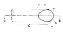
図2〜図4は本発明による送風管10の第1実施形態を示している。図示するように、第1実施形態の送風管10は直管構造となっており、好ましくは合成樹脂から射出成型法等の成型法によって作られた剛性を有するものである。送風管10の先端部、すなわち送風機14に接続される側とは反対側の端部には、当該送風管10の長手方向軸線Aに対して横向きに開口する噴口30が形成されている。また、送風管10の先端部には、送風管10内を軸線Aに沿って流れる空気流を受け、噴口30に向う方向に偏向する偏向部分32が延設されている。第1実施形態では、この偏向部分32の内面は球面形状とされている。
【0014】
送風管10の先端部は、概念的には次のようにして形成される。すなわち、送風管10の直管部分34の一端を半球状に閉塞し、この半球状の閉塞部から直管部分34の側面にかけて、軸線Aに閉塞部近傍の点36で交差し且つ軸線Aに対して所定の角度で傾斜する平面Pによって送風管10を切断することで、図2〜図4に示す形状の先端部が形成される。この形状を、偏向部分32による空気流の偏向方向に直角な方向で且つ直管部分34の長手方向軸線Aに直交する方向に沿って見た側面視の状態(図3参照)において述べるならば、噴口30を形成ないしは画定している直管部分34と偏向部分32の縁38は直線状となる。
【0015】
このような構成においては、内燃エンジン16を駆動して遠心送風機14から可撓管24を経て送風管10に空気を送り込むと、その空気流の一部は送風管10の先端部の偏向部分32の内面に衝突し、その向きが噴口30の方向に偏向される。この偏向された空気流は、軸線Aに沿って噴口30から直進しようとする空気流をも偏向させ、空気流の多くが噴口30から図3にて矢印Bで示す方向に吐出される。この吐出方向は、図12に示す従来の送風管1におけるものと変わらず、図1に示す姿勢で地面の上のゴミを吹き飛ばす場合に、水平成分が多くなり、効率的に清掃を行うことができる。
【0016】
また、軸線Aに対して直交する平面を投影面とし、そこに送風管10の直管部分34と偏向部分32を投影した場合、偏向部分32の投影図の全体が直管部分34の投影図により完全に覆われる。このことは、図4から理解されるであろう。別言するならば、偏向部分32には、直管部分34よりも横方向に突出している部分が一切ない。従って、直管部分34の横断面の面積よりも僅かに大きな隙間があれば、送風管10を先端部から真っ直ぐに通すことができる。また、そのような狭い空間に一旦送風管10の先端部を挿入することができたならば、送風管10を軸線Aを中心に自由に回転させることができ、噴口30を所望の方向に向けることができる。従って、狭い空間における清掃も容易に行うことが可能となる。
【0017】
更に、図2〜図4と図12とを比較しても分かるように、第1実施形態の送風管10を作るための金型は、湾曲部を有する従来の送風管1を作るための金型に比して、直管部分34から横方向に突出する部分がない分だけ小さな寸法とすることができる。その結果、金型費を抑制することが可能となる。
【0018】
なお、空気流を確実に軸線Aから離れる方向に偏向させるためには、偏向部分32の内面は広いことが好ましい。このため、図3において、弧度αは45度〜90度程度とすることが好ましい。
【0019】
また、本発明による送風管の偏向部分や噴口の形状は図2〜図4に示すものに限られない。例えば、図5に示す第2実施形態に係る送風管110では、直管部分34の端部に延設された偏向部分132の内面が傾斜平面となっているが、このような形状としても、図2〜図4に示す送風管10と同様な作用効果を呈することができる。
【0020】
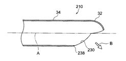
更に、図6及び図7は、本発明による送風管の第3実施形態を示している。第3実施形態に係る送風管210においては、偏向部分32は第1実施形態のものと同様に球状となっているが、噴口230を形成する直管部分34及び偏向部分32の縁238の側面視形状(図7参照)が非直線となっている点で第1実施形態のものと異なっている。
【0021】
また、第3実施形態に係る送風管210では、この縁238の側面視形状が偏向方向とは反対方向に凹状に屈曲ないしは湾曲されている。従って、噴口230を正面から見た場合、図6に示すように、噴口230の縁238は略四角形状となる。かかる形状の噴口230を有する送風管210においては、噴口230からの空気流の放射角は広くなり、図6の矢印Cで示す方向にも流れるという効果が得られる。
【0022】
図8及び図9に示す第4実施形態の送風管310は、噴口330を形成する縁338の大部分が、軸線Aに対して平行となっている。この形状では、噴口330からの空気流は、軸線Aに対して直角に近くなるという効果が得られる。
【0023】
更に、図10及び図11に示す第5実施形態の送風管410においては、噴口430を形成する縁438の側面視形状(図11参照)が、第3及び第4の実施形態と同様に非直線状であるが、他のものよりも相当に大きく湾曲されている。このため、偏向部分32の面積が小さくなり、噴口430からは軸線Aの方向に空気流の一部が吐出される。
【0024】
以上、本発明の好適な実施形態について詳細に説明したが、本発明は上記実施形態に限定されないことは言うまでもない。例えば、上記実施形態では、本発明の送風管が適用される空気吐出型清掃機が背負式のものとしているが、手持ち式やキャスタ付きの清掃機にも本発明は適用可能である。
【0025】
また、送風管は、偏向部分を除く部分の全てが剛性の直管となっている必要はなく、例えば中間部で屈曲可能な構造となっているものであってもよい。
【0026】
送風管の噴口の形状も、用途により適宜変更されるものであり、上記実施形態以外に種々考えられる。
【0027】
更に、送風管の直管部分は断面形状が円形に限られず、また、その断面形状が直管部分の全域にわたって同一である必要はない。
【0028】
【発明の効果】
以上述べたように、本発明による送風管においては、噴口から吐出される空気流は側方に向けられ、従来の湾曲先端部を有する送風管と同様に、地面の上のゴミを効率的に清掃することができる。また、先端部に側方に突出する部分がないため、狭い空間に送風管の先端部を挿入することができる。従って、作業範囲が大幅に広がる。
【0029】
また、先端部が湾曲していないことから、当該送風管を製造するための金型を小型化することができ、金型費、ひいては送風管の製造費を低減することが可能となる。
【0030】
更に、本発明による送風管を包装する場合、その包装用の箱は小さくてすみ、運搬や保管も容易となるという効果がある。
【図面の簡単な説明】
【図1】本発明による送風管が設けられた空気吐出型清掃機を示す斜視図である。
【図2】本発明の第1実施形態に係る送風管の先端部を示す正面図である。
【図3】図2のIII−III線に沿っての断面図である。
【図4】図3のIV−IV線に沿っての矢視図である。
【図5】本発明の第2実施形態に係る送風管の先端部を示す部分断面図である。
【図6】本発明の第3実施形態に係る送風管の先端部を示す正面図である。
【図7】図6のVII−VII線に沿っての断面図である。
【図8】本発明の第4実施形態に係る送風管の先端部を示す正面図である。
【図9】図9のIX−IX線に沿っての断面図である。
【図10】本発明の第5実施形態に係る送風管の先端部を示す正面図である。
【図11】図10のXI−IXI線に沿っての断面図である。
【図12】従来一般の送風管の先端部を示す断面図である。
【符号の説明】
10,110,210,310,410…送風管、12…空気吐出型清掃機、14…遠心送風機、16…内燃エンジン、18…燃料タンク、20…背負枠、30,230,330,430…噴口、32,132…偏向部分、34…直管部分、38,238.338,438…噴口を形成する縁。[0001]
BACKGROUND OF THE INVENTION
The present invention relates to a structure of a tip portion of a blower pipe in an air discharge type cleaner.
[0002]
[Prior art]
An air discharge type cleaning machine is a kind of working machine that performs cleaning by jetting air from a blower pipe using a blower and collecting dust such as fallen leaves in a desired place by the air jet flow.
[0003]
When the dust on the ground is blown off using such a cleaning machine, the operator usually holds the root portion of the blower tube by hand, and the nozzle is directed to the dust with the tip portion obliquely downward. At this time, the fact that the air flow ejected from the nozzle hole of the blower tube is directed in the horizontal direction is effective for efficiently blowing off dust. For this reason, as shown in FIG. 12, the conventional general air pipe 1 has a shape in which the tip 2 is curved.
[0004]
[Problems to be solved by the invention]
However, there is a problem that the workable range is limited when the tip 2 of the blower tube 1 is curved. For example, the curved distal end portion 2 of the blower tube 1 cannot be inserted between a narrow cage or a wall, and it may be difficult to blow off dust in the space.
[0005]
The blower tube 1 is generally molded from a synthetic resin. However, if the distal end portion 2 of the blower tube 1 is curved, the mold for molding is large by the amount of protrusion d of the distal end portion 2. There is also a problem that the mold cost becomes expensive.
[0006]
Accordingly, an object of the present invention is to provide a blower pipe for an air discharge type cleaner that can solve the above-mentioned problems in the prior art.
[0007]
[Means for Solving the Problems]
In order to achieve the above object, the present invention provides a blower pipe (10, 110,) connected directly or indirectly to an air discharge port (20) of a blower (14) in an air discharge type cleaner (12). 210, 310, 410), one end of the straight pipe portion (34) is connected to the air discharge port (22) of the blower (14), and the other end of the straight pipe portion (34) is extended. A deflection portion (32, 132) for receiving an air flow flowing in the straight pipe portion (34) and deflecting the air flow away from the longitudinal axis (A) of the straight pipe portion (34). 132) jet nozzles (30, 230, 330, 430) through which the air flow deflected by 132 is discharged are formed in the straight pipe portion (34) and the deflection portions (32, 132), and the straight pipe portion (32). ) On the projection plane orthogonal to the longitudinal axis (A) Entire projection of the deflection section (32, 132) that is covered by the projection of the straight pipe portion (34) with respect to the projection plane, than with the deflection portion (32, 132) is the straight tube portion (34) It is characterized by not having a portion protruding in the lateral direction .
[0008]
In such a configuration, the air flow is deflected in the direction away from the longitudinal axis (A) of the straight pipe portion (34) due to the presence of the deflection portions (32, 132) and discharged from the nozzle (30, 230, 330, 430). Can be made. Therefore, it has the same function as a conventional blower tube having a curved tip. Furthermore, in the present invention, since the deflecting portions (32, 132) do not protrude to the side of the straight pipe portion (34), the blower pipes (10, 110, 210, 310, 410) are handled like a straight rod-like body. Can be inserted into a narrow space.
[0009]
The shape of the nozzle hole (30), that is, the shape of the straight pipe part (34) that forms or defines the nozzle hole (30) and the edge (38) of the deflection part (32, 132) are linear (P ). Similarly, when viewed from the side, the edges (238, 338, 438) forming the nozzle holes (230, 330, 430) are non-linear and bent or curved in a direction opposite to the deflection direction. It is good. In the latter case, the radiation angle of the air flow discharged from the nozzle (230, 330, 430) is wider than the former. Here, the “side view state” described in the claims is a direction perpendicular to the deflection direction of the air flow by the deflection portions (32, 132), and is orthogonal to the longitudinal axis (A). 3, 5, 7, 9, and 11 represent a side view state in this specification.
[0010]
The inner surface of the deflecting portion (32, 132) is preferably a spherical surface or a flat surface.
[0011]
DETAILED DESCRIPTION OF THE INVENTION
DESCRIPTION OF EMBODIMENTS Hereinafter, preferred embodiments of the present invention will be described in detail with reference to the drawings. In the drawings, the same or corresponding parts are denoted by the same reference numerals.
[0012]
FIG. 1 shows a back-loaded air
[0013]
2 to 4 show a first embodiment of the
[0014]
The tip of the
[0015]
In such a configuration, when the
[0016]
Further, when a plane orthogonal to the axis A is used as a projection plane and the
[0017]
Further, as can be seen from a comparison between FIGS. 2 to 4 and FIG. 12, the mold for making the
[0018]
In order to reliably deflect the air flow away from the axis A, the inner surface of the
[0019]
Further, the shape of the deflecting portion and the nozzle hole of the blower tube according to the present invention is not limited to those shown in FIGS. For example, in the
[0020]
Furthermore, FIG.6 and FIG.7 has shown 3rd Embodiment of the ventilation pipe by this invention. In the
[0021]
Further, in the
[0022]
In the
[0023]
Furthermore, in the
[0024]
As mentioned above, although preferred embodiment of this invention was described in detail, it cannot be overemphasized that this invention is not limited to the said embodiment. For example, in the above-described embodiment, the air discharge type cleaning machine to which the blower pipe of the present invention is applied is of a backpack type, but the present invention can also be applied to a handheld type or a cleaning machine with casters.
[0025]
Further, the blast pipe does not have to be a rigid straight pipe except for the deflecting portion, and may have a structure that can be bent at an intermediate portion, for example.
[0026]
The shape of the nozzle hole of the blower tube is also appropriately changed depending on the application, and variously considered other than the above embodiment.
[0027]
Furthermore, the cross-sectional shape of the straight pipe portion of the blower pipe is not limited to a circular shape, and the cross-sectional shape does not have to be the same over the entire area of the straight pipe portion.
[0028]
【The invention's effect】
As described above, in the air blow pipe according to the present invention, the air flow discharged from the nozzle is directed to the side, and the dust on the ground is efficiently removed in the same manner as the air blow pipe having the conventional curved tip portion. Can be cleaned. Moreover, since there is no part which protrudes to a side at a front-end | tip part, the front-end | tip part of a ventilation pipe | tube can be inserted in a narrow space. Therefore, the work range is greatly expanded.
[0029]
In addition, since the tip portion is not curved, it is possible to reduce the size of a mold for manufacturing the blower tube, and to reduce the mold cost, and consequently the manufacturing cost of the blower tube.
[0030]
Furthermore, when packaging the blast tube according to the present invention, the packaging box can be made small, and transport and storage are facilitated.
[Brief description of the drawings]
FIG. 1 is a perspective view showing an air discharge type cleaning machine provided with a blow pipe according to the present invention.
FIG. 2 is a front view showing a front end portion of a blower pipe according to the first embodiment of the present invention.
FIG. 3 is a cross-sectional view taken along line III-III in FIG.
4 is a view taken along the line IV-IV in FIG. 3;
FIG. 5 is a partial cross-sectional view showing a distal end portion of a blower pipe according to a second embodiment of the present invention.
FIG. 6 is a front view showing a front end portion of a blower pipe according to a third embodiment of the present invention.
7 is a cross-sectional view taken along line VII-VII in FIG.
FIG. 8 is a front view showing a distal end portion of a blower pipe according to a fourth embodiment of the present invention.
9 is a cross-sectional view taken along line IX-IX in FIG.
FIG. 10 is a front view showing a distal end portion of a blower pipe according to a fifth embodiment of the present invention.
11 is a sectional view taken along line XI-IXI in FIG.
FIG. 12 is a cross-sectional view showing a tip portion of a conventional general blast tube.
[Explanation of symbols]
DESCRIPTION OF SYMBOLS 10,110,210,310,410 ... Air blow pipe, 12 ... Air discharge type cleaner, 14 ... Centrifugal blower, 16 ... Internal combustion engine, 18 ... Fuel tank, 20 ... Backpack frame, 30, 230, 330, 430 ...
Claims (5)
一端側が前記送風機(14)の前記空気吐出口(22)に接続される側となる直管部分(34)と、
前記直管部分(34)の他端に延設され、前記直管部分(34)内を流れる空気流を受けて前記直管部分(34)の長手方向軸線(A)から離れる方向に偏向させる偏向部分(32,132)と
を備え、
前記偏向部分(32)により偏向された空気流が吐出される噴口(30,230,330,430)が前記直管部分(34)及び前記偏向部分(32,132)に形成されており、且つ、
前記直管部分(34)の前記長手方向軸線(A)に直交する投影面に対する前記偏向部分(32,132)の投影図の全体が前記投影面に対する前記直管部分(34)の投影図により覆われ、もって前記偏向部分(32,132)が前記直管部分(34)よりも横方向に突出する部分を有しないようになっていることを特徴とする空気吐出型清掃機の送風管。A blower pipe (10, 110, 210, 310, 410) connected to the air discharge port (22) of the blower (14) in the air discharge type cleaner (12),
A straight pipe portion (34) whose one end side is a side connected to the air discharge port (22) of the blower (14);
Extending to the other end of the straight pipe portion (34), it receives an air flow flowing through the straight pipe portion (34) and deflects it in a direction away from the longitudinal axis (A) of the straight pipe portion (34). A deflection portion (32, 132),
The nozzle holes (30, 230, 330, 430) through which the air flow deflected by the deflection part (32) is discharged are formed in the straight pipe part (34) and the deflection parts (32, 132), and ,
The whole projection view of the deflection portion (32, 132) with respect to the projection plane orthogonal to the longitudinal axis (A) of the straight pipe portion (34) is obtained by the projection view of the straight pipe portion (34) with respect to the projection plane. A blower pipe for an air discharge type cleaner, wherein the blower pipe is covered so that the deflection part (32, 132) does not have a part projecting laterally from the straight pipe part (34) .
Priority Applications (2)
| Application Number | Priority Date | Filing Date | Title |
|---|---|---|---|
| JP2001029891A JP3672828B2 (en) | 2001-02-06 | 2001-02-06 | Air discharge type cleaning machine air duct |
| US09/925,750 US6526624B2 (en) | 2001-02-06 | 2001-08-09 | Blower tube for air-jet type cleaner |
Applications Claiming Priority (1)
| Application Number | Priority Date | Filing Date | Title |
|---|---|---|---|
| JP2001029891A JP3672828B2 (en) | 2001-02-06 | 2001-02-06 | Air discharge type cleaning machine air duct |
Publications (2)
| Publication Number | Publication Date |
|---|---|
| JP2002227153A JP2002227153A (en) | 2002-08-14 |
| JP3672828B2 true JP3672828B2 (en) | 2005-07-20 |
Family
ID=18894183
Family Applications (1)
| Application Number | Title | Priority Date | Filing Date |
|---|---|---|---|
| JP2001029891A Expired - Fee Related JP3672828B2 (en) | 2001-02-06 | 2001-02-06 | Air discharge type cleaning machine air duct |
Country Status (2)
| Country | Link |
|---|---|
| US (1) | US6526624B2 (en) |
| JP (1) | JP3672828B2 (en) |
Families Citing this family (23)
| Publication number | Priority date | Publication date | Assignee | Title |
|---|---|---|---|---|
| DE10230289A1 (en) * | 2002-07-05 | 2004-01-22 | Andreas Stihl Ag & Co. | blower |
| JP5091399B2 (en) | 2005-11-15 | 2012-12-05 | ハスクバーナ・ゼノア株式会社 | Chainsaw |
| JP2007176128A (en) * | 2005-12-28 | 2007-07-12 | Komatsu Zenoah Co | Chain saw |
| JP2007177774A (en) * | 2005-12-28 | 2007-07-12 | Komatsu Zenoah Co | Two-cycle engine |
| US8178019B2 (en) * | 2006-09-28 | 2012-05-15 | Hitachi Metals, Ltd. | Method and apparatus for producing ceramic honeycomb structure |
| US20080092976A1 (en) * | 2006-10-20 | 2008-04-24 | Komatsu Zenoah Co. | Blower duct |
| US20080295274A1 (en) * | 2007-05-29 | 2008-12-04 | Husqvarna Outdoor Products Inc. | Accordion vacuum tube relief |
| US20090038106A1 (en) * | 2007-08-10 | 2009-02-12 | Zenoah Co., Ltd. | Engine blower |
| JP5061048B2 (en) * | 2008-07-01 | 2012-10-31 | ニューデルタ工業株式会社 | Air blower |
| JP5572060B2 (en) * | 2010-10-22 | 2014-08-13 | 株式会社やまびこ | Air blower |
| US20140068892A1 (en) * | 2012-09-11 | 2014-03-13 | Bryan Richard Chambers | Blower Cleaning Attachment |
| US9883634B2 (en) | 2012-09-13 | 2018-02-06 | Franco Romito | Attachment for air blower |
| US9486120B2 (en) | 2013-07-17 | 2016-11-08 | Tacony Corporation | Wearer comfort backpack vacuum |
| JP6437745B2 (en) * | 2014-06-20 | 2018-12-12 | 株式会社マキタ | nozzle |
| US20160108924A1 (en) * | 2014-10-17 | 2016-04-21 | Mean Green Products, LLC | Battery-powered, low-noise backpack blower |
| US10327392B2 (en) | 2014-11-05 | 2019-06-25 | Mean Green Products, LLC | Battery-powered debris blower |
| JP6511651B2 (en) * | 2015-01-08 | 2019-05-15 | ニューデルタ工業株式会社 | Air blower |
| JP2019018190A (en) * | 2017-07-21 | 2019-02-07 | 株式会社マキタ | Blowing work machine |
| JP7109235B2 (en) * | 2018-04-02 | 2022-07-29 | シャープ株式会社 | blowing nozzles and blowers |
| EP3866578A4 (en) | 2018-10-17 | 2022-10-05 | Generac Power Systems, Inc. | Deck height control system |
| US11032973B2 (en) | 2019-07-26 | 2021-06-15 | Generac Power Systems, Inc. | Battery-operated electric mower |
| JP7416664B2 (en) | 2020-06-11 | 2024-01-17 | 株式会社やまびこ | Fluid jet pipe and blower work equipment |
| JP7229417B1 (en) * | 2022-11-25 | 2023-03-02 | 肇 行田 | Discharge pipe and blower |
Family Cites Families (7)
| Publication number | Priority date | Publication date | Assignee | Title |
|---|---|---|---|---|
| US2586145A (en) * | 1948-05-21 | 1952-02-19 | Breuer Electric Mfg Company | Draft applying tool for portable motor-blower units |
| US4053962A (en) * | 1975-12-16 | 1977-10-18 | Mcdowell Robert V | Suction-cleaning dust retriever |
| US5280667A (en) * | 1990-02-23 | 1994-01-25 | Coathupe John E | Collection devices |
| GB2299749B (en) * | 1995-03-11 | 1998-09-02 | Black & Decker Inc | A blower vacuum device of improved design |
| US5652995A (en) * | 1995-07-28 | 1997-08-05 | Wci Outdoor Products, Inc. | Nozzle for lawn and garden blower |
| US5813088A (en) * | 1997-07-23 | 1998-09-29 | Wagner; Jeffrey F. | Backpack blower |
| US6076231A (en) * | 1998-08-28 | 2000-06-20 | Bucher; Charles | Nozzle for a lawn and garden blower |
-
2001
- 2001-02-06 JP JP2001029891A patent/JP3672828B2/en not_active Expired - Fee Related
- 2001-08-09 US US09/925,750 patent/US6526624B2/en not_active Expired - Fee Related
Also Published As
| Publication number | Publication date |
|---|---|
| US6526624B2 (en) | 2003-03-04 |
| US20020104186A1 (en) | 2002-08-08 |
| JP2002227153A (en) | 2002-08-14 |
Similar Documents
| Publication | Publication Date | Title |
|---|---|---|
| JP3672828B2 (en) | Air discharge type cleaning machine air duct | |
| JP4340629B2 (en) | Upright vacuum cleaner | |
| US5970577A (en) | Brush head assembly for a vacuum cleaner | |
| US7789922B1 (en) | Cyclonic chamber for air filtration devices | |
| US20070209154A1 (en) | Flexible Crevice Tool for Vacuum Cleaners | |
| US4553284A (en) | Vacuum cleaner universal nozzle | |
| JPH04164422A (en) | Vacuum cleaner | |
| US6026541A (en) | Multi-purpose attachment tool for a hand-held vacuum cleaner | |
| JPH0662977A (en) | Hand dryer | |
| ES2814125T3 (en) | Suction nozzle for collecting coarse material and fine dust | |
| US7132017B2 (en) | Low-pressure cleaning system using high velocity high volume air | |
| KR100271702B1 (en) | Suction nozzle off a vacuum cleaner and vacuum cleaner having the same | |
| JP4836856B2 (en) | Nozzle device | |
| JP2018196352A (en) | Collecting device and attachment | |
| US5280856A (en) | Debris shield apparatus | |
| JP2019178511A (en) | Blower work machine | |
| JP3765083B2 (en) | Cleaning device for indoor unit of air conditioner | |
| CN107743370A (en) | Vacuum cleaner nozzle and the vacuum cleaner for including vacuum cleaner nozzle | |
| CN217327830U (en) | Securing device of cleaner fan and cleaner | |
| JPH0563567B2 (en) | ||
| JP6707976B2 (en) | Vacuum cleaner | |
| KR100767116B1 (en) | Suction port assembly for vacuum cleaner | |
| JP4340630B2 (en) | Upright vacuum cleaner | |
| JP6503918B2 (en) | Electric vacuum cleaner | |
| JP4480549B2 (en) | Suction nozzle for wet vacuum cleaner |
Legal Events
| Date | Code | Title | Description |
|---|---|---|---|
| A131 | Notification of reasons for refusal |
Free format text: JAPANESE INTERMEDIATE CODE: A131 Effective date: 20041221 |
|
| A521 | Request for written amendment filed |
Free format text: JAPANESE INTERMEDIATE CODE: A523 Effective date: 20050210 |
|
| TRDD | Decision of grant or rejection written | ||
| A01 | Written decision to grant a patent or to grant a registration (utility model) |
Free format text: JAPANESE INTERMEDIATE CODE: A01 Effective date: 20050411 |
|
| A61 | First payment of annual fees (during grant procedure) |
Free format text: JAPANESE INTERMEDIATE CODE: A61 Effective date: 20050420 |
|
| R150 | Certificate of patent or registration of utility model |
Free format text: JAPANESE INTERMEDIATE CODE: R150 |
|
| FPAY | Renewal fee payment (event date is renewal date of database) |
Free format text: PAYMENT UNTIL: 20090428 Year of fee payment: 4 |
|
| FPAY | Renewal fee payment (event date is renewal date of database) |
Free format text: PAYMENT UNTIL: 20090428 Year of fee payment: 4 |
|
| FPAY | Renewal fee payment (event date is renewal date of database) |
Free format text: PAYMENT UNTIL: 20100428 Year of fee payment: 5 |
|
| FPAY | Renewal fee payment (event date is renewal date of database) |
Free format text: PAYMENT UNTIL: 20110428 Year of fee payment: 6 |
|
| FPAY | Renewal fee payment (event date is renewal date of database) |
Free format text: PAYMENT UNTIL: 20130428 Year of fee payment: 8 |
|
| FPAY | Renewal fee payment (event date is renewal date of database) |
Free format text: PAYMENT UNTIL: 20140428 Year of fee payment: 9 |
|
| LAPS | Cancellation because of no payment of annual fees |