EP2067447B1 - Steuerbare kathetervorrichtung zur chemoembolisation und/oder embolisation von gefässstrukturen, tumoren und/oder organen - Google Patents
Steuerbare kathetervorrichtung zur chemoembolisation und/oder embolisation von gefässstrukturen, tumoren und/oder organen Download PDFInfo
- Publication number
- EP2067447B1 EP2067447B1 EP06795243A EP06795243A EP2067447B1 EP 2067447 B1 EP2067447 B1 EP 2067447B1 EP 06795243 A EP06795243 A EP 06795243A EP 06795243 A EP06795243 A EP 06795243A EP 2067447 B1 EP2067447 B1 EP 2067447B1
- Authority
- EP
- European Patent Office
- Prior art keywords
- catheter
- lumen
- drug
- distal end
- energy
- Prior art date
- Legal status (The legal status is an assumption and is not a legal conclusion. Google has not performed a legal analysis and makes no representation as to the accuracy of the status listed.)
- Not-in-force
Links
Images


Classifications
-
- A—HUMAN NECESSITIES
- A61—MEDICAL OR VETERINARY SCIENCE; HYGIENE
- A61M—DEVICES FOR INTRODUCING MEDIA INTO, OR ONTO, THE BODY; DEVICES FOR TRANSDUCING BODY MEDIA OR FOR TAKING MEDIA FROM THE BODY; DEVICES FOR PRODUCING OR ENDING SLEEP OR STUPOR
- A61M25/00—Catheters; Hollow probes
- A61M25/01—Introducing, guiding, advancing, emplacing or holding catheters
- A61M25/0105—Steering means as part of the catheter or advancing means; Markers for positioning
- A61M25/0133—Tip steering devices
- A61M25/0147—Tip steering devices with movable mechanical means, e.g. pull wires
-
- A—HUMAN NECESSITIES
- A61—MEDICAL OR VETERINARY SCIENCE; HYGIENE
- A61B—DIAGNOSIS; SURGERY; IDENTIFICATION
- A61B18/00—Surgical instruments, devices or methods for transferring non-mechanical forms of energy to or from the body
- A61B18/04—Surgical instruments, devices or methods for transferring non-mechanical forms of energy to or from the body by heating
- A61B18/12—Surgical instruments, devices or methods for transferring non-mechanical forms of energy to or from the body by heating by passing a current through the tissue to be heated, e.g. high-frequency current
- A61B18/14—Probes or electrodes therefor
- A61B18/1492—Probes or electrodes therefor having a flexible, catheter-like structure, e.g. for heart ablation
-
- A—HUMAN NECESSITIES
- A61—MEDICAL OR VETERINARY SCIENCE; HYGIENE
- A61M—DEVICES FOR INTRODUCING MEDIA INTO, OR ONTO, THE BODY; DEVICES FOR TRANSDUCING BODY MEDIA OR FOR TAKING MEDIA FROM THE BODY; DEVICES FOR PRODUCING OR ENDING SLEEP OR STUPOR
- A61M25/00—Catheters; Hollow probes
- A61M25/01—Introducing, guiding, advancing, emplacing or holding catheters
- A61M25/0105—Steering means as part of the catheter or advancing means; Markers for positioning
- A61M25/0133—Tip steering devices
- A61M25/0136—Handles therefor
-
- A—HUMAN NECESSITIES
- A61—MEDICAL OR VETERINARY SCIENCE; HYGIENE
- A61M—DEVICES FOR INTRODUCING MEDIA INTO, OR ONTO, THE BODY; DEVICES FOR TRANSDUCING BODY MEDIA OR FOR TAKING MEDIA FROM THE BODY; DEVICES FOR PRODUCING OR ENDING SLEEP OR STUPOR
- A61M25/00—Catheters; Hollow probes
- A61M25/10—Balloon catheters
-
- A—HUMAN NECESSITIES
- A61—MEDICAL OR VETERINARY SCIENCE; HYGIENE
- A61B—DIAGNOSIS; SURGERY; IDENTIFICATION
- A61B18/00—Surgical instruments, devices or methods for transferring non-mechanical forms of energy to or from the body
- A61B18/18—Surgical instruments, devices or methods for transferring non-mechanical forms of energy to or from the body by applying electromagnetic radiation, e.g. microwaves
- A61B18/20—Surgical instruments, devices or methods for transferring non-mechanical forms of energy to or from the body by applying electromagnetic radiation, e.g. microwaves using laser
- A61B18/22—Surgical instruments, devices or methods for transferring non-mechanical forms of energy to or from the body by applying electromagnetic radiation, e.g. microwaves using laser the beam being directed along or through a flexible conduit, e.g. an optical fibre; Couplings or hand-pieces therefor
- A61B18/24—Surgical instruments, devices or methods for transferring non-mechanical forms of energy to or from the body by applying electromagnetic radiation, e.g. microwaves using laser the beam being directed along or through a flexible conduit, e.g. an optical fibre; Couplings or hand-pieces therefor with a catheter
-
- A—HUMAN NECESSITIES
- A61—MEDICAL OR VETERINARY SCIENCE; HYGIENE
- A61B—DIAGNOSIS; SURGERY; IDENTIFICATION
- A61B17/00—Surgical instruments, devices or methods, e.g. tourniquets
- A61B17/00234—Surgical instruments, devices or methods, e.g. tourniquets for minimally invasive surgery
- A61B2017/00292—Surgical instruments, devices or methods, e.g. tourniquets for minimally invasive surgery mounted on or guided by flexible, e.g. catheter-like, means
- A61B2017/003—Steerable
-
- A—HUMAN NECESSITIES
- A61—MEDICAL OR VETERINARY SCIENCE; HYGIENE
- A61B—DIAGNOSIS; SURGERY; IDENTIFICATION
- A61B17/00—Surgical instruments, devices or methods, e.g. tourniquets
- A61B17/22—Implements for squeezing-off ulcers or the like on the inside of inner organs of the body; Implements for scraping-out cavities of body organs, e.g. bones; Calculus removers; Calculus smashing apparatus; Apparatus for removing obstructions in blood vessels, not otherwise provided for
- A61B2017/22051—Implements for squeezing-off ulcers or the like on the inside of inner organs of the body; Implements for scraping-out cavities of body organs, e.g. bones; Calculus removers; Calculus smashing apparatus; Apparatus for removing obstructions in blood vessels, not otherwise provided for with an inflatable part, e.g. balloon, for positioning, blocking, or immobilisation
- A61B2017/22065—Functions of balloons
- A61B2017/22067—Blocking; Occlusion
-
- A—HUMAN NECESSITIES
- A61—MEDICAL OR VETERINARY SCIENCE; HYGIENE
- A61B—DIAGNOSIS; SURGERY; IDENTIFICATION
- A61B18/00—Surgical instruments, devices or methods for transferring non-mechanical forms of energy to or from the body
- A61B2018/00053—Mechanical features of the instrument of device
- A61B2018/00214—Expandable means emitting energy, e.g. by elements carried thereon
-
- A—HUMAN NECESSITIES
- A61—MEDICAL OR VETERINARY SCIENCE; HYGIENE
- A61B—DIAGNOSIS; SURGERY; IDENTIFICATION
- A61B2218/00—Details of surgical instruments, devices or methods for transferring non-mechanical forms of energy to or from the body
- A61B2218/001—Details of surgical instruments, devices or methods for transferring non-mechanical forms of energy to or from the body having means for irrigation and/or aspiration of substances to and/or from the surgical site
- A61B2218/002—Irrigation
Definitions
- This invention pertains generally to the technical sector of the chemoembolization and/or emobilization of vascular structures, of benign, premalignant, or malignant tumours, and/or of partial or complete organs of a patient.
- the present invention relates to a steerable catheter, which comprises the emission of at least energy from radiofrequency source and laser source before, during, and/or after the administration of a chemotherapeutic and/or embolization drug .
- a steerable catheter which comprises the emission of at least energy from radiofrequency source and laser source before, during, and/or after the administration of a chemotherapeutic and/or embolization drug .
- other types of energies can be also incorporated in the catheter, which are preferably selected from the intense pulse light microwaves (IPL) or the high-intensity focused ultrasound (HIFU).
- IPL intense pulse light microwaves
- HIFU high-intensity focused ultrasound
- the purpose of the catheter device is energy transfer to the surrounding tissue in order to involve tissue changes and/or environmental changes, which promotes the effect of the administered drug directly and/or indirectly: directly by changing the drug itself structurally, or indirectly by changing the surrounding tissue in region where the drug was administered.
- Other changes can result in an increased therapeutic effect, due to induced necroses to tissue, changes in blood flow (increased, decreased and/or stopped), and a better drug control (higher concentration, less drug wash out, less backflow) in the treated area.
- Tissue ablations techniques with the assistance of different types of energy sources are well described in literature. These methods were already used in the open surgery and invasive treatment. The simplest example is applying an electric energy source during open surgery for tissue coagulation.
- an apparatus for treating a biological tissue of a patient in situ comprising an optical fibre for guiding a coherent waveform to a fibre tip for discharge of light energy from said fibre tip in a direction of energy discharge, and a guide tip coupled to said fibre tip.
- an inflatable balloon is generally used at the distal end of a catheter, as described in US Patent No. 3435826 and US No. 4762130 .
- a medical device assembly adapted for ablating tissue comprising an ablation member coupled to the distal end portion of an elongate body, wherein the ablation member comprises an inflatable balloon and an ablation element.
- the ablation element is adapted to ablate at least a portion of the circumferential region of tissue to form the conduction block.
- the ablation member further includes at least one sensor (i.e., thermocouple) attached to a wall of the inflatable balloon.
- laser and radio-frequency sources are used in an ablative and non-ablative manner, and the energy is used for a direct energy transfer-tissue contact interaction, however this two energy sources has not used in combined from in this device.
- An device with essentially triangular lumen and with a regular round external circumference is disclosed in the patent WO2005 099802 .
- An specifically embodiment of this device includes secondary lumens of different shapes and positions within a wall, coexisting said secondary lumens with said triangular main lumen of the tube of the invention.
- this device need means for guiding the flexible tube into a cavity, inserted in the external slit or in an internal slit or entirely is external, attached internally to the internal surface of the tube or superficially to the external surface of the tube.
- the radiofrequency treatment combined with pharmaceutical compositions is described to ablate tumour masses by means of a needle having one or more tines, which can comprise a pharmaceutical composition.
- the present principal problem is the drug wash out and drug control in the treated area, since high concentration and/or high toxic embolic and/or chemotherapeutic drugs cannot be used safely as a systemic and interarterial treatments.
- connection drugs with the other carriers or to antibodies can be used with the aim of changing the molecules, and these are yet in study.
- tissue interaction for better drug control and/or modification has not been described or known in the hereby-described field.
- Increasing the drug potentiality by inducing environmental changes for example changing temperature, or inducing a local light source in tissue can induce a better therapeutic effect.
- Said environmental changes can also comprise those changes of the surrounding tissue by, for example, inducing changes in blood flow in the treated area.
- These changes can be permanent and/or non-permanent: non-permanent changes can be vasodilatation and/or vasoconstriction, and/or blood extraction in the treated area; and permanent changes can be vaso-occlusion, induced tissue necroses, or changes in permeability of the tissue barriers and/cell barriers in the treated area. All these changes can be induced before, during and/or after drug administration. All the described methods could change the drug-tissue interaction.
- Embodiments of the present invention relate to an improved apparatus with the aim of obtaining better results in the treatment with embolization and/or chemoembolization.
- the embodiment of the invention relates to a better drug control and/or tissue control in the treated area, to ensure a better drug - energy - tissue interaction.
- modification and/or activation of the drug by an energy source will result in a new therapeutic window for the treatment of very aggressive tumours or vascular malformations.
- accidental drug leakage in the non-therapeutic area will be able to be better avoided.
- by increasing blood flow by vasodilatation it will be able to obtain an increased drug absorption in tissue.
- these new devices could simplify remarkably the treatment protocols by ensuring complete and effective devices, which can be located in situ in an organ by catherization, and/or by direct puncture of soft tissue or organs, and in which as well as different energy sources as different drugs, and/or vacuum can be administered.
- Such technologies will enable to treat a wide range of pathologies with less instrumentation for the patient.
- By using the catheter of the invention more local invasive techniques in the treated area can be performed through smaller incisions and a smaller amount of catheters, with a lesser morbidity, lesser traumatic to the surrounding tissue and lesser side effects.
- the embodiment of the invention is engineered for human use; however, it can be also suitable for other species in vivo and/or in vitro and in the largest sense of the word, and/or in tissue engineering and/or others.
- an apparatus which enables reliable and/or controlled destruction of tissue by the combination of a drug, dye and/or the administration in situ of active and/or non active particles and/or substances, liquids, gases and others or a combination of these mentioned above with an energy source and contrasts.
- the apparatus comprises essentially a catheter, which incorporates different drug conduits and vacuum conduits associated with different electrodes, radiofrequency conduits, optical fibres and other components, and the apparatus is connected with an energy unit.
- an inflatable balloon is provided at the distal end of the catheter to help occlude a vessel.
- the energy assist embolization catheter embodiments of the invention can also incorporate the necessary devices to introduce the catheter in an anatomical site in the treated area or at a distance of the site. This instrumentation can enable the physician to expose the active distal end in the therapeutic area by different techniques: tunnelling, catherization and/or dissection, and/or direct puncture.
- different energy sources and/or energy conduits which were introduced in and/or built in the catheter can be used. Thereby the physician can dissect, coagulate and ablate tissue with optimum results.
- Other devices that can be incorporated in the catheter are: a guide wire, sheets, distractors.
- the catheter according to the invention comprises an elongated flexible tube inside of which a plurality of conduits and wires go through until the distal end of the catheter: at least one conduit for drug administration, an optical fibre cable inside of which comprises one or more optical fibres to pass on the laser light, and a guiding wire to carry the catherization out.
- one or two electrodes/s or conductive layers can be positioned on the outer surface of the catheter distal end to emit radiofrequency waves generated by a radiofrequency source at the distal end of the catheter.
- Each of these electrodes is connected to a conductive element, which is electrically coupled to a radiofrequency generator.
- a guiding mechanism can also be incorporated within the flexible catheter tube; said guiding mechanism being formed of at least one steering or pull cable.
- the described catheter can also include at least one inflatable balloon with its corresponding conduits for inflating/deflating said balloon.
- Each balloon requires at least one conduit to obtain the inflation or deflation of it, which forms an independent lumen.
- a conduit for a dye or other liquids such as refrigerating fluids to refrigerate the electrodes can be provided inside the catheter tube.
- catheter tube delivery devices for other energies' transmission can be incorporated.
- These energy sources which can be connected to the probe, can have different wavelengths, be different types of light sources or be other types of energy.
- the distal end of said catheter comprises at least one independent lumen for the drug administration, one central lumen for the guiding wire, one lumen for the optical fibre/s and another lumen for the radiofrequency energy wire; and at least one electrode placed on or near to the distal end of the catheter.
- the balloon/s quoted above is/are placed in the vicinity of said distal end and can be positioned not only in target tissue or organs, cavities (such the thorax, sinu) or conduits (arterial, venous), but also for example in hepatic duct, or urethra etc.
- the inflation of the balloon can alter the flow in the conduit, can prevent leakage of an injected agent, or can create a physical separation, compression, or shield in tissue.
- the electrical wire/s for activating the electrode/s and the optical fibre cable which contains the optical fibre/s will locate close one to each other in order to reduce the catheter tube's diameter and make the catheter compacter and easier to use.
- one or two conduits or lumens for said electrical wires are used, this to use the system as a unique or bipolar unit. If a unipolar configuration is used, the ground electrode is placed apart from the catheter distal end.
- Said electrical wire/s may be fabricated from one or more lengths of tubing, secured at to the tube or advantageously at other energy conduits such as an optic fibre.
- Different electrodes can be isolated with insulating material.
- Said electrode can have different configurations on cross-section, and even coiled into a helix.
- the electrode can be incorporated into a mesh, or can include lengths of sheet or bar material to an other support, having a semicircular configuration or other geometry thereby forming a part of and/or a complete lumen which can be uses for example to mount the optic fibre.
- Other geometric forms are possible for the electrodes, such as concentric configuration.
- the electrode itself can be fabricated from any metal (for example gold, platinum or tungsten), metal deposits over a carrier (gold-plated stainless steel, gold deposited polyamide or platinum deposited polyester).
- This carrier can be incorporated or be an effective other component of the catheter and can be very malleable, must be resistant to external forces, must bend this allowing catherization.
- the catheter has at least one or more optical fibres. These can be in independent conduits or can be coupled. It is important that the light diffusing energy into the human tissue is in a uniform manner. The energy is diffused radially and outwardly in a uniform distribution along the entire length of the fibre assuring a proper heating or energy distribution at the therapeutic end.
- the optical fibre will be connected to a laser source, which is located out of the catheter, and in collaboration with the selected connection devices.
- At the distal end of the catheter temperature and/or Doppler probes can be associated with the existing electrodes, in order to measure the temperature and the blood flow respectively.
- One possible embodiment for a communal lumen where bipolar electrodes are used is providing an inner electrode and an outer electrode of cylindrical configuration at a concentrical position, between of which several optical fibres are arranged.
- Another possible embodiment for a communal lumen where bipolar electrodes are used is having two electrodes with U-shaped section situated face to face, in between of which several optical fibres are arranged.
- the optical fibres are arranged in the space between the two bipolar electrodes, so acting advantageously as an insulating element for the bipolar electrodes.
- said steering or pull wire/s which function is to guide the distal end of the catheter, locate near the electrodes and optical fibres in order to optimize the steering of the distal end.
- the steering or pull wire end is radio opaque or echo opaque.
- Extra markings for navigation and mapping can be added (e.g. for detection by infrared camera, MRI, CT related procedures).
- the steerable catheter can also incorporate an information center unit, which is an electronic device that measures different catheter current parameters of the catheter, such as the pipe, the current use or the wave flanges.
- Said information center unit is located near the proximal end of the catheter and it is connected to the energy generator unit to transmit the measuring parameters to the generator.
- the central lumen of the catheter receives the guiding wire for catherization. Through this lumen active or non-active substances can be administered.
- This part of the catheter can be connected to a volumetric pump for perfusion of the probe or probe cooling or other purposes. Through this conduit measurement probes or energy probes can also be introduced.
- the connector has a valve mechanism and luer adaptor.
- conduits join into a handle that incorporates the different ports to the different units of the catheter, and a steering mechanism of the distal end of the catheter.
- Certain of these ports incorporate a luer adaptor, or another tubing or an electric, or a fibre, or another connection, capable of transmitting the necessary source of energy or substance.
- the handle incorporates at least one or more conduit to supply the energy on the catheter therapeutic end.
- the conduits are connected to the energy source by a connection device.
- the multi-conduit catheter and its additional structures can be fabricated from different raw materials having the desired qualifications, the desired pattern, cross sectional profile, and dimension. It can contain rod, wire, tubes, sheets, ribbons, optical fibres etc. These raw materials can be fabricated by extruding, injection moulding, forging, rolling, casting and others to obtain the right shape and configuration.
- the different elements of the catheter may be cut from raw material by water jet cutting, laser cutting, US cutting, EDM machining, photochemical etching, or others to obtain the lumens, pores, ports, and other features from the raw material. All the different components of the catheter can be assembled and/or unified by laser welding, adhesive bonding, ultrasonic welding, radiofrequency welding, soldering, spot welding, or other means.
- Various components of the probe which can be fabricated from at least one wire, tube, ribbon, sheet, rod, band or bar of raw material, which were cut the desired configuration, can be thermally changes into the desired 3-dimensional configuration.
- the components can be stressed into the resting configuration form using mandrels and/or forming fixtures, having the desired resting shape of the puncturing components and heated to a temperature between 300 and 650 degrees Celsius for a predetermined period of time. Once the material has reached the desired temperature for desired period, the component is quenched and chilled by different methods, and/ or gases, and/or liquids.
- Components from the catheter can have different patterns to allow the correct geometry for assemblage. These can be oval, circular, rectangular, square, trapezoid, and others. These elements can be cut to the desired length and stressed to the desired shape by different manufacturing proceeds as mentioned above.
- the different components of the catheter can be tumbled, sand blasted, bead blasted, chemically etched, ground, mechanically polished, electro polished, or otherwise treated to remove any edges and/or procedure a smooth surface.
- Additional markings can be added in order to make navigation technique possible.
- tubular shaped body of the catheter In reference to the tubular shaped body of the catheter, it can be fabricated from a metal, metal alloy, PEBAX.RTM, polyester, polyurethane, urethane, silicone, polyamide, other thermoplastic, thermoset plastic, or elastomer, or braided metallic wires covered with polymer. Said tubing(s) may have a circular, elliptical, or any geometry, this depending on the stiffness, configuration of the different parts, and assemblage.
- the substance to be used in the inflatable balloon conduits and balloon can be a gas or liquid or a mixture.
- the liquid can be an active agent, or can be a substance absorbing light or diffusing light. It can be air, water, oil, contrast agents, perflueocarbons, saline solutions, dyes, etc.
- a valve For deflation and inflation and for the maintenance of a calibrated volume there is at the end of the in(de)flate member a valve.
- the dispenser On the valve a syringe or other calibrated dispenser can be connected, the dispenser can work by volume or by pressure.
- Advantageously by using pressure and volume data information can be obtain of the target area.
- the shaft of this part of the catheter can be manufactured of different materials selected in the group of the stainless steel, polyamide, polyethylene, polystryren, polycarbonate, extrudable polymer, thermoplastic, silicone, rubber, composite, brass, titanium, aluminium, ceramic etc; This list is not limitative.
- the inflatable member can be made of an inelastic or elastic material.
- the balloon can take the shape of the target tissue, conduit, or space.
- tissue, or conduit, or space will take the form of the inflated member.
- Said inflated member can have any configuration in size or shape, and preferably its shape can be spherical, ovoid, elliptical, cylindrical and other.
- the wall of the balloon must be supple enough to change in size and configuration as the introduced substance volume is changed, but at the same time it must be also stiff enough to be manipulated during instrumentation and placement, and finally it must be resistant to high pressure and temperature.
- the inflatable member can be manufactured from material selected in the group of silastic, silicone, c-flex, polyester, mylar, polyurethane, polyvinyl, polyethylene, latex, rubber; this list is not limitative.
- Figures 1a-1c illustrate the catheter proximal end (11) comprising a handle (13), at one end of which the catheter tube (27) is connected and at the opposite end the different ports (47) where the different conduits and wires are connected, in order to arrange all the elements in the proper way within the catheter tube (27).
- a conduit (21) for drug administration, an energy conduit (34) for containing the energy elements and a guiding wire conduit (44) for containing the guiding wire (15) are steered towards the interior of the body (27) of the catheter (27).
- a conduit (14) for the inflation/deflation of the balloon (28) can also be incorporated and also a steering mechanism (41).
- a volumetric pump (43) is incorporated for perfusion of the probe or probe cooling. Additionally, the respective connector has a valve (42).
- a connector (18) is provided, in order to join said conduit (14) with a pressure device (20), for example a pump or similar, which function is the inflation/deflation of the balloon (28).
- a balloon connector is provided to connect with a pressure device (20), such as a pump or similar, which function is the inflation and the deflation of the balloon depending on the required configuration.
- an energy connector (39) is provided, the inputs of which are an electrical connector (16) and an optical fibre connector (25), which both are also connected to the corresponding energy sources: the radiofrequency source (17) and the laser energy source (26) respectively.
- the distribution of the different ports (47) in the handle (13) can be any, for example the ports (47) being arranged in the same side, as it is shown in figure n° 1b, or being arranged in both sides of the handle (13), as it is shown in figure n° 1c.
- the distal end (12) of a steerable catheter (10) may comprise essentially a flexible tube (27) inside of which a plurality of conduits and wires go through, thus forming the multi-lumen catheter.
- a catheter (10) which is the simplest one, a lumen for drug administration (21), a radiofrequency lumen (46) for the electric conduits (45) for activating the polar electrodes (30), a lumen (24) for the transmission of the laser energy inside of which comprises two optical fibres (29), a central lumen (44) for the guiding wire (15) and a steering cable (33) with a circumferential perimeter that surrounds the rest of the quoted lumens.
- an inflatable balloon (28) is also provided, which is inflated/deflated by means of a substance that flows inside the two conduits (14) and being steered by the pressure device (20).
- a lumen for a dye (40) or other liquids which is not shown in the figures, such as refrigerating fluids to refrigerate the electrode/s can also be incorporated.
- the distal end (12) of the catheter (10) has two different openings: two side openings (32) for the drug (21) and dye (40) conduits, and a central opening (31) for the energy conduits (46) and (24) and the wires (15) and (33) located in a central part of the end of the catheter tube (27).
- a steerable catheter 10 comprising a flexible tube (27) inside of which a plurality of conduits and wires go through, thus forming at the end a multi-lumen catheter (10).
- two conduits for drug (21) are provided, as well as a steering cable (33) and a balloon (28) with its respective conduits (14).
- the special feature of it is the energy lumen (34), which is a communal lumen inside of which there is the central lumen (44) for the guiding wire (15) in a central position surrounded by optical fibres (29).
- the inner electrode (36) is the outer wall of the central lumen (44), which is a conductive layer, whereas the outer electrode (35) is located in a concentrical position regarding the inner electrode (36) in the outer layer of the lumen (34).
- the bipolar electrodes (35-36) several optical fibres (29) are arranged, which act as an insulating material.
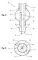
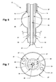
- the multi-lumen catheter (10) in a variation of this embodiment of the multi-lumen catheter (10), as shown in Fig. 6-7 , it also incorporates two conduits for drug administration (21), a balloon (28) with its corresponding conduits (14), two steering cable (33) and a common energy lumen (34).
- said common energy lumen (34) has another configuration; the central lumen (44) for the guiding wire (15) is located in a central position and its outer wall is not active.
- multi-lumen catheter (10) As illustrated in figures n° 8-9, another embodiment of the multi-lumen catheter (10) is disclosed. It also includes a common energy lumen (34) with a bipolar U-shaped section electrodes (37) and a central lumen (44), but said electrodes (37) are located close to the inner surface of said conduit (34).
- the distal end (12) of the catheter (10) has four independent lumens: the central one is the energy lumen (34) and the peripheral lumens are for drug (21) or dye (40).
- the central energy lumen (34) has a symmetric triangular cross section, and in the space between the walls of the triangle and the walls of the tubular body (27) there are three independent lumens with a curved cross section.
- a steering cable (33) is provided at the vertexes of said triangle in order to guide perfectly the distal end (12) of the catheter (10).
- the central lumen (44) is situated in a central position of said energy lumen (34) and its outer wall is the inner electrode.
- the outer electrode is placed within the energy lumen (34) and in a concentrical configuration.
- the distal end (12) of the multi-lumen catheter (10) has a very similar configuration to the previous embodiment, but with the difference that the outer electrode is placed close to the inner surface of the catheter tube (27).
Claims (8)
- Steuerbarer Katheter (10) für die Chemoembolisation und/oder die Embolisation von Gefäßstrukturen, Tumoren und/oder Organen, bestehend aus einem Schlauch (27) mit einem distalen und einem proximalen Ende, aus einem Energieelement, das dazu geeignet ist, in die das Zielgewebe umgebenden Bereiche Energie zu übertragen und mit einem verabreichten Medikament zusammenzuwirken, aus mindestens einem sich auf der Innenseite des Schlauchkörpers (27) des Katheters (10) befindlichen und sich direkt zum distalen Ende (12) des Katheters (10) erstreckenden Steuerkabel (33), mit dem das distale Ende des Katheters gelenkt werden kann, und aus mindestens drei unabhängigen Lumina, von denen mindestens ein Lumen (21) zur Verabreichung von Medikamenten in das Zielgewebe, mindestens ein gemeinsames Lumen für die Energiezufuhr (34) oder zwei unabhängige Lumina für die Energieelemente und mindestens ein zentrales Lumen (44) zur Aufnahme des Führungsdrahtes (15) für die Katheterisierung vorgesehen sind, wobei das proximale Ende (11) des Katheters (10) mit einem Griffstück (13) verbunden ist, das mehrere Ports für den Anschluss und die Einführung der verschiedenen Elemente in die entsprechenden Lumina umfasst, und wobei der Katheter (10) optional auch einen Verschlussballon (28) aufweisen kann, der nahe dem distalen Ende (12) des Katheters (10) angeordnet ist und ein weiteres Lumen zur Steuerung des Stoffes zum Aufblasen und Entleeren des Ballons umfasst, dadurch gekennzeichnet, dass:- das distale Ende (12) des Katheters (10) derart gestaltet ist, dass es fünf unabhängige Lumina umfasst: drei Lumina (21) für die Verabreichung von Medikamenten oder Zufuhr von anderen Flüssigkeiten oder Färbemitteln, ein gemeinsames Energielumen mit dreieckförmigem Querschnitt (34), das alle bei der Energieübertragung mitwirkenden Elemente enthält, ein zentrales Lumen (44), das im Inneren des gemeinsamen Lumens (34) mittig angeordnet ist; zwei bipolare Elektroden (30), die am Ende oder nahe des Endes des Katheters (10) angeordnet sind; und mindestens ein Steuerkabel (33); wobei
die Energieelemente Folgendes umfassen:- mindestens einen Leiterdraht (45), der geeignet ist, um mittels der gewählten Anschlussvorrichtungen, wie z.B. einen Steckverbinder (16), an eine Hochfrequenzquelle (17) entlang des gemeinsamen oder unabhängigen Lumens an das distale Ende (12) des Katheters (10) angeschlossen zu werden, und mindestens eine Elektrode (30), die am Ende oder nahe des distalen Endes des Katheters (10) angeordnet ist, und- mindestens einen Lichtwellenleiter (29), der geeignet ist, um mittels der gewählten Anschlussvorrichtungen, wie z.B. einen Steckverbinder (25), entlang des gemeinsamen oder unabhängigen Lumens an das distale Ende (12) des Katheters (10) angeschlossen zu werden. - Steuerbarer Katheter nach Anspruch 1, bei dem die bipolaren Elektroden (30) einen runden Querschnitt aufweisen und konzentrisch angeordnet sind: die äußere Elektrode (35) ist nahe der Innenwand des Schlauchkörpers (27) des Katheters (10) angeordnet und die innere Elektrode bildet die Außenwand des zentralen Lumens (44); der Raum zwischen den Elektroden (30) wird von mehreren Lichtwellenleitern (29) eingenommen.
- Steuerbarer Katheter nach Anspruch 1, bei dem die bipolaren Elektroden (30) einen runden Querschnitt aufweisen und konzentrisch angeordnet sind: die äußere Elektrode (35) ist nahe der Außenwand des Schlauchkörpers (27) des Katheters (10) angeordnet und die innere Elektrode (36) bildet die Außenwand des zentralen Lumens (44); der Raum zwischen den Elektroden (30) wird von mehreren Lichtwellenleitem eingenommen.
- Steuerbarer Katheter nach Anspruch 1, bei dem das Steuerkabel (33) einen Querschnitt mit einem umlaufenden Rand aufweist und um die restlichen Lumina (14, 24, 44 und 46) des Katheters (10) herum angeordnet ist.
- Steuerbarer Katheter nach Anspruch 1, bei dem die Medikamentenleitung/en (21) über die gewählten Anschlussvorrichtungen, wie z.B. einen Steckverbinder (22), an einen Medikamentenapplikator (23) angeschlossen ist/sind.
- Steuerbarer Katheter nach Anspruch 1, bei dem die Temperaturfühler und/oder Doppler-Sonden am distalen Ende (12) des Katheters (10) mit den Elektroden (30) integriert werden können.
- Steuerbarer Katheter nach Anspruch 1, bei dem das distale Ende (12) des Schlauchkörpers (27) des Katheters (10) auf der Seite der Medikamentenabgabe eine Medikamentenkonzentrationsvorrichtung aufweisen kann.
- Steuerbarer Katheter nach Anspruch 1, bei dem das distale Ende (12) des Schlauchkörpers (27) des Katheters (10) mit zwei Arten von Öffnungen versehen ist:- seitliche Öffnungen, um den Austritt der Leitungen für die Medikamente (21) und Färbemittel (40) aus dem Katheterschlauch zu ermöglichen, wobei sich die seitlichen Öffnungen in einer vorderen Position am Katheterschlauch befinden; und- eine zentrale Öffnung, um den Austritt der Energieleitungen (Hochfrequenz (46) und Laser (24)), des Führungsdrahtes und des oder der Steuerkabel aus dem Katheterschlauch zu ermöglichen.
Applications Claiming Priority (1)
| Application Number | Priority Date | Filing Date | Title |
|---|---|---|---|
| PCT/IB2006/002209 WO2008004018A1 (es) | 2006-06-30 | 2006-06-30 | Dispositivo de cateter dirigido y metodo para la quimioembolizacion y/o embolizacion de estructuras vasculares, tumorales y/o de organos |
Publications (2)
| Publication Number | Publication Date |
|---|---|
| EP2067447A1 EP2067447A1 (de) | 2009-06-10 |
| EP2067447B1 true EP2067447B1 (de) | 2012-08-15 |
Family
ID=37719431
Family Applications (1)
| Application Number | Title | Priority Date | Filing Date |
|---|---|---|---|
| EP06795243A Not-in-force EP2067447B1 (de) | 2006-06-30 | 2006-06-30 | Steuerbare kathetervorrichtung zur chemoembolisation und/oder embolisation von gefässstrukturen, tumoren und/oder organen |
Country Status (4)
| Country | Link |
|---|---|
| US (1) | US8784401B2 (de) |
| EP (1) | EP2067447B1 (de) |
| ES (1) | ES2393365T3 (de) |
| WO (1) | WO2008004018A1 (de) |
Families Citing this family (13)
| Publication number | Priority date | Publication date | Assignee | Title |
|---|---|---|---|---|
| US20040226556A1 (en) | 2003-05-13 | 2004-11-18 | Deem Mark E. | Apparatus for treating asthma using neurotoxin |
| US8483831B1 (en) | 2008-02-15 | 2013-07-09 | Holaira, Inc. | System and method for bronchial dilation |
| EP2662046B1 (de) | 2008-05-09 | 2023-03-15 | Nuvaira, Inc. | Systeme und Baugruppen zur Behandlung eines Bronchialbaumes |
| EP2470255A4 (de) * | 2009-08-24 | 2013-02-06 | Ron L Alterman | Vorrichtung für transzerebrale elektrophorese und verfahren zu ihrer verwendung |
| CN107049479B (zh) | 2009-10-27 | 2020-10-16 | 努瓦拉公司 | 具有可冷却的能量发射组件的递送装置 |
| US8911439B2 (en) | 2009-11-11 | 2014-12-16 | Holaira, Inc. | Non-invasive and minimally invasive denervation methods and systems for performing the same |
| KR101820542B1 (ko) | 2009-11-11 | 2018-01-19 | 호라이라 인코포레이티드 | 조직을 치료하고 협착을 제어하기 위한 방법, 기구 및 장치 |
| US8461766B2 (en) | 2010-12-09 | 2013-06-11 | General Electric Company | Driver circuit with primary side state estimator for inferred output current feedback sensing |
| CN103027750B (zh) * | 2012-11-23 | 2015-02-11 | 刘宗军 | 一种经皮肾动脉内电消融球囊射频导管 |
| US9398933B2 (en) | 2012-12-27 | 2016-07-26 | Holaira, Inc. | Methods for improving drug efficacy including a combination of drug administration and nerve modulation |
| US9662509B2 (en) | 2013-05-23 | 2017-05-30 | Cook Medical Technologies Llc | Intraluminal activation system and method of activating an inactive agent |
| EP3522807A1 (de) | 2016-10-04 | 2019-08-14 | Avent, Inc. | Gekühlte hf-sonden |
| WO2018160454A1 (en) * | 2017-02-28 | 2018-09-07 | University Of Florida Research Foundation, Inc. | Controlling esophageal temperature during cardiac ablation |
Citations (1)
| Publication number | Priority date | Publication date | Assignee | Title |
|---|---|---|---|---|
| WO2005099802A2 (en) * | 2004-04-19 | 2005-10-27 | Etview Ltd. | Imaging catheter |
Family Cites Families (15)
| Publication number | Priority date | Publication date | Assignee | Title |
|---|---|---|---|---|
| US3435826A (en) | 1964-05-27 | 1969-04-01 | Edwards Lab Inc | Embolectomy catheter |
| US4565200A (en) | 1980-09-24 | 1986-01-21 | Cosman Eric R | Universal lesion and recording electrode system |
| US4762130A (en) | 1987-01-15 | 1988-08-09 | Thomas J. Fogarty | Catheter with corkscrew-like balloon |
| US5462544A (en) | 1993-05-05 | 1995-10-31 | Energy Life System Corporation | Continuous heart tissue mapping and lasing catheter |
| US6056744A (en) | 1994-06-24 | 2000-05-02 | Conway Stuart Medical, Inc. | Sphincter treatment apparatus |
| US6652515B1 (en) * | 1997-07-08 | 2003-11-25 | Atrionix, Inc. | Tissue ablation device assembly and method for electrically isolating a pulmonary vein ostium from an atrial wall |
| US6869431B2 (en) * | 1997-07-08 | 2005-03-22 | Atrionix, Inc. | Medical device with sensor cooperating with expandable member |
| US6500174B1 (en) | 1997-07-08 | 2002-12-31 | Atrionix, Inc. | Circumferential ablation device assembly and methods of use and manufacture providing an ablative circumferential band along an expandable member |
| US6120476A (en) | 1997-12-01 | 2000-09-19 | Cordis Webster, Inc. | Irrigated tip catheter |
| EP1502624B1 (de) * | 2000-08-17 | 2007-02-14 | William N. Borkan | Stimulationskatheter mit Elektrode und Faseroptik |
| EP2213257B1 (de) * | 2003-03-28 | 2013-04-24 | C. R. Bard, Inc. | Katheter mit geflochtenem Maschengeflecht |
| WO2005044124A1 (en) | 2003-10-30 | 2005-05-19 | Medical Cv, Inc. | Apparatus and method for laser treatment |
| US20060009404A1 (en) | 2004-07-09 | 2006-01-12 | Williams Jason R | Tumor ablation in combination with pharmaceutical compositions |
| US20080015569A1 (en) * | 2005-02-02 | 2008-01-17 | Voyage Medical, Inc. | Methods and apparatus for treatment of atrial fibrillation |
| US8657814B2 (en) * | 2005-08-22 | 2014-02-25 | Medtronic Ablation Frontiers Llc | User interface for tissue ablation system |
-
2006
- 2006-06-30 ES ES06795243T patent/ES2393365T3/es active Active
- 2006-06-30 US US12/308,851 patent/US8784401B2/en not_active Expired - Fee Related
- 2006-06-30 WO PCT/IB2006/002209 patent/WO2008004018A1/es active Application Filing
- 2006-06-30 EP EP06795243A patent/EP2067447B1/de not_active Not-in-force
Patent Citations (1)
| Publication number | Priority date | Publication date | Assignee | Title |
|---|---|---|---|---|
| WO2005099802A2 (en) * | 2004-04-19 | 2005-10-27 | Etview Ltd. | Imaging catheter |
Also Published As
| Publication number | Publication date |
|---|---|
| WO2008004018A1 (es) | 2008-01-10 |
| US20090275878A1 (en) | 2009-11-05 |
| EP2067447A1 (de) | 2009-06-10 |
| US8784401B2 (en) | 2014-07-22 |
| ES2393365T3 (es) | 2012-12-20 |
Similar Documents
| Publication | Publication Date | Title |
|---|---|---|
| EP2067447B1 (de) | Steuerbare kathetervorrichtung zur chemoembolisation und/oder embolisation von gefässstrukturen, tumoren und/oder organen | |
| JP4280865B2 (ja) | 経皮プリングル閉塞デバイス | |
| AU2001245794B2 (en) | Lung treatment apparatus | |
| US7160296B2 (en) | Tissue ablation apparatus and method | |
| US8007497B2 (en) | Ablation probe with heat sink | |
| JP2021164694A (ja) | 瘻を形成するためのデバイスおよび方法 | |
| EP1715910B1 (de) | Endoskopische multi-lumensvorrichtung und deren verbrauchverfahren | |
| AU2001245794A1 (en) | Lung treatment apparatus | |
| WO2006026210A2 (en) | Devices for delivering agents to tissue region while preventing leakage | |
| CA2768454A1 (en) | Open-irrigated ablation catheter with turbulent flow | |
| WO2002067797A2 (en) | Tissue surface treatment apparatus and method | |
| BRPI0708159A2 (pt) | instrumentos de ablação e métodos relacionados | |
| KR20080110224A (ko) | 카테터 시스템 | |
| CN220124759U (zh) | 一种用于生成冲击波的装置 | |
| US20230414277A1 (en) | Pulsed electric field delivery device | |
| CN220045996U (zh) | 一种冲击波球囊和可手持冲击波碎石治疗装置 | |
| WO2022187821A1 (en) | Device and method for thermal modulation of tissue | |
| CN117281604A (zh) | 脉冲电场递送装置 | |
| EP3041408A1 (de) | Multifunktioneller elektrophysiologischer diagnosekatheter für behandlungen in der elektrokardiologie |
Legal Events
| Date | Code | Title | Description |
|---|---|---|---|
| PUAI | Public reference made under article 153(3) epc to a published international application that has entered the european phase |
Free format text: ORIGINAL CODE: 0009012 |
|
| AK | Designated contracting states |
Kind code of ref document: A1 Designated state(s): AT BE BG CH CY CZ DE DK EE ES FI FR GB GR HU IE IS IT LI LT LU LV MC NL PL PT RO SE SI SK TR |
|
| AX | Request for extension of the european patent |
Extension state: AL BA HR MK RS |
|
| 17P | Request for examination filed |
Effective date: 20081218 |
|
| 17Q | First examination report despatched |
Effective date: 20091208 |
|
| GRAP | Despatch of communication of intention to grant a patent |
Free format text: ORIGINAL CODE: EPIDOSNIGR1 |
|
| DAX | Request for extension of the european patent (deleted) | ||
| RTI1 | Title (correction) |
Free format text: STEERABLE CATHETER DEVICE FOR THE CHEMOEMBOLIZATION AND/OR EMBOLIZATION OF VASCULAR STRUCTURES, TUMOURS AND/OR ORGANS |
|
| GRAS | Grant fee paid |
Free format text: ORIGINAL CODE: EPIDOSNIGR3 |
|
| GRAA | (expected) grant |
Free format text: ORIGINAL CODE: 0009210 |
|
| AK | Designated contracting states |
Kind code of ref document: B1 Designated state(s): AT BE BG CH CY CZ DE DK EE ES FI FR GB GR HU IE IS IT LI LT LU LV MC NL PL PT RO SE SI SK TR |
|
| REG | Reference to a national code |
Ref country code: CH Ref legal event code: EP Ref country code: GB Ref legal event code: FG4D Ref country code: AT Ref legal event code: REF Ref document number: 570389 Country of ref document: AT Kind code of ref document: T Effective date: 20120815 |
|
| REG | Reference to a national code |
Ref country code: IE Ref legal event code: FG4D |
|
| REG | Reference to a national code |
Ref country code: DE Ref legal event code: R096 Ref document number: 602006031477 Country of ref document: DE Effective date: 20121018 |
|
| REG | Reference to a national code |
Ref country code: NL Ref legal event code: VDEP Effective date: 20120815 |
|
| REG | Reference to a national code |
Ref country code: ES Ref legal event code: FG2A Ref document number: 2393365 Country of ref document: ES Kind code of ref document: T3 Effective date: 20121220 |
|
| REG | Reference to a national code |
Ref country code: AT Ref legal event code: MK05 Ref document number: 570389 Country of ref document: AT Kind code of ref document: T Effective date: 20120815 |
|
| PG25 | Lapsed in a contracting state [announced via postgrant information from national office to epo] |
Ref country code: FI Free format text: LAPSE BECAUSE OF FAILURE TO SUBMIT A TRANSLATION OF THE DESCRIPTION OR TO PAY THE FEE WITHIN THE PRESCRIBED TIME-LIMIT Effective date: 20120815 Ref country code: LT Free format text: LAPSE BECAUSE OF FAILURE TO SUBMIT A TRANSLATION OF THE DESCRIPTION OR TO PAY THE FEE WITHIN THE PRESCRIBED TIME-LIMIT Effective date: 20120815 Ref country code: AT Free format text: LAPSE BECAUSE OF FAILURE TO SUBMIT A TRANSLATION OF THE DESCRIPTION OR TO PAY THE FEE WITHIN THE PRESCRIBED TIME-LIMIT Effective date: 20120815 Ref country code: CY Free format text: LAPSE BECAUSE OF FAILURE TO SUBMIT A TRANSLATION OF THE DESCRIPTION OR TO PAY THE FEE WITHIN THE PRESCRIBED TIME-LIMIT Effective date: 20120815 Ref country code: IS Free format text: LAPSE BECAUSE OF FAILURE TO SUBMIT A TRANSLATION OF THE DESCRIPTION OR TO PAY THE FEE WITHIN THE PRESCRIBED TIME-LIMIT Effective date: 20121215 |
|
| PG25 | Lapsed in a contracting state [announced via postgrant information from national office to epo] |
Ref country code: GR Free format text: LAPSE BECAUSE OF FAILURE TO SUBMIT A TRANSLATION OF THE DESCRIPTION OR TO PAY THE FEE WITHIN THE PRESCRIBED TIME-LIMIT Effective date: 20121116 Ref country code: PT Free format text: LAPSE BECAUSE OF FAILURE TO SUBMIT A TRANSLATION OF THE DESCRIPTION OR TO PAY THE FEE WITHIN THE PRESCRIBED TIME-LIMIT Effective date: 20121217 Ref country code: SE Free format text: LAPSE BECAUSE OF FAILURE TO SUBMIT A TRANSLATION OF THE DESCRIPTION OR TO PAY THE FEE WITHIN THE PRESCRIBED TIME-LIMIT Effective date: 20120815 Ref country code: LV Free format text: LAPSE BECAUSE OF FAILURE TO SUBMIT A TRANSLATION OF THE DESCRIPTION OR TO PAY THE FEE WITHIN THE PRESCRIBED TIME-LIMIT Effective date: 20120815 Ref country code: PL Free format text: LAPSE BECAUSE OF FAILURE TO SUBMIT A TRANSLATION OF THE DESCRIPTION OR TO PAY THE FEE WITHIN THE PRESCRIBED TIME-LIMIT Effective date: 20120815 Ref country code: SI Free format text: LAPSE BECAUSE OF FAILURE TO SUBMIT A TRANSLATION OF THE DESCRIPTION OR TO PAY THE FEE WITHIN THE PRESCRIBED TIME-LIMIT Effective date: 20120815 |
|
| PG25 | Lapsed in a contracting state [announced via postgrant information from national office to epo] |
Ref country code: NL Free format text: LAPSE BECAUSE OF FAILURE TO SUBMIT A TRANSLATION OF THE DESCRIPTION OR TO PAY THE FEE WITHIN THE PRESCRIBED TIME-LIMIT Effective date: 20120815 |
|
| PG25 | Lapsed in a contracting state [announced via postgrant information from national office to epo] |
Ref country code: DK Free format text: LAPSE BECAUSE OF FAILURE TO SUBMIT A TRANSLATION OF THE DESCRIPTION OR TO PAY THE FEE WITHIN THE PRESCRIBED TIME-LIMIT Effective date: 20120815 Ref country code: RO Free format text: LAPSE BECAUSE OF FAILURE TO SUBMIT A TRANSLATION OF THE DESCRIPTION OR TO PAY THE FEE WITHIN THE PRESCRIBED TIME-LIMIT Effective date: 20120815 Ref country code: CZ Free format text: LAPSE BECAUSE OF FAILURE TO SUBMIT A TRANSLATION OF THE DESCRIPTION OR TO PAY THE FEE WITHIN THE PRESCRIBED TIME-LIMIT Effective date: 20120815 Ref country code: EE Free format text: LAPSE BECAUSE OF FAILURE TO SUBMIT A TRANSLATION OF THE DESCRIPTION OR TO PAY THE FEE WITHIN THE PRESCRIBED TIME-LIMIT Effective date: 20120815 |
|
| PG25 | Lapsed in a contracting state [announced via postgrant information from national office to epo] |
Ref country code: IT Free format text: LAPSE BECAUSE OF FAILURE TO SUBMIT A TRANSLATION OF THE DESCRIPTION OR TO PAY THE FEE WITHIN THE PRESCRIBED TIME-LIMIT Effective date: 20120815 Ref country code: SK Free format text: LAPSE BECAUSE OF FAILURE TO SUBMIT A TRANSLATION OF THE DESCRIPTION OR TO PAY THE FEE WITHIN THE PRESCRIBED TIME-LIMIT Effective date: 20120815 |
|
| PLBE | No opposition filed within time limit |
Free format text: ORIGINAL CODE: 0009261 |
|
| STAA | Information on the status of an ep patent application or granted ep patent |
Free format text: STATUS: NO OPPOSITION FILED WITHIN TIME LIMIT |
|
| 26N | No opposition filed |
Effective date: 20130516 |
|
| PG25 | Lapsed in a contracting state [announced via postgrant information from national office to epo] |
Ref country code: BG Free format text: LAPSE BECAUSE OF FAILURE TO SUBMIT A TRANSLATION OF THE DESCRIPTION OR TO PAY THE FEE WITHIN THE PRESCRIBED TIME-LIMIT Effective date: 20121115 |
|
| REG | Reference to a national code |
Ref country code: DE Ref legal event code: R097 Ref document number: 602006031477 Country of ref document: DE Effective date: 20130516 |
|
| PG25 | Lapsed in a contracting state [announced via postgrant information from national office to epo] |
Ref country code: MC Free format text: LAPSE BECAUSE OF FAILURE TO SUBMIT A TRANSLATION OF THE DESCRIPTION OR TO PAY THE FEE WITHIN THE PRESCRIBED TIME-LIMIT Effective date: 20120815 |
|
| REG | Reference to a national code |
Ref country code: CH Ref legal event code: PL |
|
| REG | Reference to a national code |
Ref country code: IE Ref legal event code: MM4A |
|
| PG25 | Lapsed in a contracting state [announced via postgrant information from national office to epo] |
Ref country code: CH Free format text: LAPSE BECAUSE OF NON-PAYMENT OF DUE FEES Effective date: 20130630 Ref country code: LI Free format text: LAPSE BECAUSE OF NON-PAYMENT OF DUE FEES Effective date: 20130630 Ref country code: IE Free format text: LAPSE BECAUSE OF NON-PAYMENT OF DUE FEES Effective date: 20130630 |
|
| PG25 | Lapsed in a contracting state [announced via postgrant information from national office to epo] |
Ref country code: TR Free format text: LAPSE BECAUSE OF FAILURE TO SUBMIT A TRANSLATION OF THE DESCRIPTION OR TO PAY THE FEE WITHIN THE PRESCRIBED TIME-LIMIT Effective date: 20120815 |
|
| PG25 | Lapsed in a contracting state [announced via postgrant information from national office to epo] |
Ref country code: LU Free format text: LAPSE BECAUSE OF NON-PAYMENT OF DUE FEES Effective date: 20130630 Ref country code: HU Free format text: LAPSE BECAUSE OF FAILURE TO SUBMIT A TRANSLATION OF THE DESCRIPTION OR TO PAY THE FEE WITHIN THE PRESCRIBED TIME-LIMIT; INVALID AB INITIO Effective date: 20060630 |
|
| REG | Reference to a national code |
Ref country code: FR Ref legal event code: PLFP Year of fee payment: 11 |
|
| REG | Reference to a national code |
Ref country code: FR Ref legal event code: PLFP Year of fee payment: 12 |
|
| PGFP | Annual fee paid to national office [announced via postgrant information from national office to epo] |
Ref country code: GB Payment date: 20170629 Year of fee payment: 12 Ref country code: FR Payment date: 20170629 Year of fee payment: 12 |
|
| PGFP | Annual fee paid to national office [announced via postgrant information from national office to epo] |
Ref country code: DE Payment date: 20170831 Year of fee payment: 12 Ref country code: ES Payment date: 20170720 Year of fee payment: 12 |
|
| PGFP | Annual fee paid to national office [announced via postgrant information from national office to epo] |
Ref country code: BE Payment date: 20170630 Year of fee payment: 12 |
|
| REG | Reference to a national code |
Ref country code: DE Ref legal event code: R119 Ref document number: 602006031477 Country of ref document: DE |
|
| GBPC | Gb: european patent ceased through non-payment of renewal fee |
Effective date: 20180630 |
|
| REG | Reference to a national code |
Ref country code: BE Ref legal event code: MM Effective date: 20180630 |
|
| PG25 | Lapsed in a contracting state [announced via postgrant information from national office to epo] |
Ref country code: FR Free format text: LAPSE BECAUSE OF NON-PAYMENT OF DUE FEES Effective date: 20180630 Ref country code: DE Free format text: LAPSE BECAUSE OF NON-PAYMENT OF DUE FEES Effective date: 20190101 Ref country code: GB Free format text: LAPSE BECAUSE OF NON-PAYMENT OF DUE FEES Effective date: 20180630 |
|
| PG25 | Lapsed in a contracting state [announced via postgrant information from national office to epo] |
Ref country code: BE Free format text: LAPSE BECAUSE OF NON-PAYMENT OF DUE FEES Effective date: 20180630 |
|
| REG | Reference to a national code |
Ref country code: ES Ref legal event code: FD2A Effective date: 20190916 |
|
| PG25 | Lapsed in a contracting state [announced via postgrant information from national office to epo] |
Ref country code: ES Free format text: LAPSE BECAUSE OF NON-PAYMENT OF DUE FEES Effective date: 20180701 |