EP2066844B1 - Method and device for inserting a drainage wick - Google Patents
Method and device for inserting a drainage wick Download PDFInfo
- Publication number
- EP2066844B1 EP2066844B1 EP07820730A EP07820730A EP2066844B1 EP 2066844 B1 EP2066844 B1 EP 2066844B1 EP 07820730 A EP07820730 A EP 07820730A EP 07820730 A EP07820730 A EP 07820730A EP 2066844 B1 EP2066844 B1 EP 2066844B1
- Authority
- EP
- European Patent Office
- Prior art keywords
- drainage wick
- inserting tube
- soil
- anchorage component
- wick
- Prior art date
- Legal status (The legal status is an assumption and is not a legal conclusion. Google has not performed a legal analysis and makes no representation as to the accuracy of the status listed.)
- Not-in-force
Links
- 238000000034 method Methods 0.000 title claims abstract description 33
- 239000002689 soil Substances 0.000 claims description 71
- XLYOFNOQVPJJNP-UHFFFAOYSA-N water Substances O XLYOFNOQVPJJNP-UHFFFAOYSA-N 0.000 claims description 16
- 239000000463 material Substances 0.000 claims description 9
- 239000003566 sealing material Substances 0.000 claims 2
- 230000000295 complement effect Effects 0.000 description 3
- 238000007596 consolidation process Methods 0.000 description 3
- 239000011499 joint compound Substances 0.000 description 3
- 238000004873 anchoring Methods 0.000 description 2
- 239000004927 clay Substances 0.000 description 2
- 238000011109 contamination Methods 0.000 description 2
- 230000002706 hydrostatic effect Effects 0.000 description 2
- 238000003780 insertion Methods 0.000 description 2
- 230000037431 insertion Effects 0.000 description 2
- 238000009434 installation Methods 0.000 description 2
- 230000014759 maintenance of location Effects 0.000 description 2
- 239000004576 sand Substances 0.000 description 2
- 238000007789 sealing Methods 0.000 description 2
- 229910000278 bentonite Inorganic materials 0.000 description 1
- 239000000440 bentonite Substances 0.000 description 1
- SVPXDRXYRYOSEX-UHFFFAOYSA-N bentoquatam Chemical compound O.O=[Si]=O.O=[Al]O[Al]=O SVPXDRXYRYOSEX-UHFFFAOYSA-N 0.000 description 1
- 238000004891 communication Methods 0.000 description 1
- 238000010586 diagram Methods 0.000 description 1
- 230000003292 diminished effect Effects 0.000 description 1
- 238000011900 installation process Methods 0.000 description 1
- 239000007788 liquid Substances 0.000 description 1
- 238000012423 maintenance Methods 0.000 description 1
- 239000011159 matrix material Substances 0.000 description 1
- 230000000149 penetrating effect Effects 0.000 description 1
- 230000035515 penetration Effects 0.000 description 1
- 229920000642 polymer Polymers 0.000 description 1
- 239000011148 porous material Substances 0.000 description 1
- 238000012545 processing Methods 0.000 description 1
- 230000000717 retained effect Effects 0.000 description 1
- 239000011435 rock Substances 0.000 description 1
- 238000012546 transfer Methods 0.000 description 1
Images



Classifications
-
- E—FIXED CONSTRUCTIONS
- E02—HYDRAULIC ENGINEERING; FOUNDATIONS; SOIL SHIFTING
- E02D—FOUNDATIONS; EXCAVATIONS; EMBANKMENTS; UNDERGROUND OR UNDERWATER STRUCTURES
- E02D3/00—Improving or preserving soil or rock, e.g. preserving permafrost soil
- E02D3/02—Improving by compacting
- E02D3/10—Improving by compacting by watering, draining, de-aerating or blasting, e.g. by installing sand or wick drains
Definitions
- the invention relates to a method of inserting a drainage wick into the ground
- Drainage wicks are commonly used for carrying out vertical draining in the ground in order to improve the strength of ground and generally consist of paper material in the form of strips or of a band-shaped plastic core enclosed in a suitable filter material.
- Such drainage wicks are widely used to consolidate soft compressible soils (such as clays and/or fine grained soils). Consolidation of a compressible soil occurs as pore water is squeezed from the soil matrix. The installation of vertical drains provides shortened drainage paths for the water to exit the soil and thus can reduce significantly the soil settlement time.
- the drainage wick In order to insert such a drainage wick in the ground, for example to a depth of 10 m up to 40 or 60 m, the drainage wick is threaded through an inserting tube or column after the tube is driven into the ground. When such an inserting tube is then extracted from the ground, the drainage wick remains in the soil, the soil pressurizes against the drainage wick, and water may travel through the permeable filter material of the drainage wick along the plastic core.
- the drainage wick is threaded through the inserting tube and an anchorage component, such as a plate or bar, is attached to the lower end of said drainage wick.
- the drainage wick and anchorage component are then driven downwardly into the ground with or through said inserting tube. Said inserting tube is then pulled up whereby said anchorage component and said drainage wick are permitted to remain in the ground.
- the anchorage component is not pulled up and can easily remain lodged in position in the ground.
- the soil around the anchorage component can rearrange and apply an hydrostatic pressure on the anchorage component so that the anchorage component remains in its position when the tie is tightened and the drainage wick pulls on it during the step of further pulling up the inserting tube.
- Such steps allow blockage of drainage wick during the step of pulling up the inserting tube and drainage wick.
- a complementary feature to the method comprises the step of introducing compressed air in the inserting tube after the drainage wick jamming step. Introducing compressed air in the inserting tube enables pushing an anchorage component downwardly in the soil and makes its anchorage easier. Such a process is faster and less expensive than known processes where water is used to hold down an anchorage component.
- the method comprises the steps of:
- Adding a shutter to the driving tube may be useful if elements of the soil, namely mud, may penetrate into the inserting tube when driving it downwardly into the ground.
- An embodiment of the present invention includes an anchorage component having such a shutter.
- the method comprises the step of filling the soil zone around the anchorage component with a sealing or retention material such as mud, clay or water expandable material, such as bentonite, water activated polymer, before and/or when the inserting tube and the drainage wick are pulled up and before the drainage wick is permitted to remain in the soil. It is then possible to further rearrange the soil during the step of pulling up the inserting tube and drainage wick and seal the soil around the anchorage component and/or the tie. Furthermore when water expandable material is used, water of the soil contacts the water expandable material which expands in volume and enhances the sealing and maintenance of the anchorage component into the soil.
- a sealing or retention material such as mud, clay or water expandable material, such as bentonite, water activated polymer
- the distance between the position the anchorage component is permitted to remain in the soil and the position the drainage wick end is permitted to remain in the soil is at least about 0.40 m.
- the tie or connector may be selected from the list comprising a rope, a cord, a cable, a strap.
- a water expandable material may be included in, or coated on said tie.
- the anchorage component and drainage wick are driven downwardly into a layer of hard soil situated underneath a layer of soft soil and the anchorage component is permitted to remain in the layer of hard soil while said drainage wick is permitted to remain in said layer of soft soil.
- a layer of "soft soil” is a layer wherein anchoring is difficult such as, for example, mud, muddy soils, limon, vase, pit, pitty soils, soft clays.
- a layer of "hard soil” is a layer where anchoring is easier than in a soft soil layer.
- Hard soil layers are, for example, comprised of sand, sand and gravel, impervious clay, marl, weathered rocks. Hard soils are usually more permeable than soft soils.
- embodiments of the invention also relate to a not claimed device for inserting a drainage wick downwardly into the earth which includes:
- a device for inserting a drainage wick downwardly into the earth typically includes:
- the blockage element is a gas expandable balloon.
- the blockage element is a movable plate, such as a folding plate or a plate that slides in a slot arranged in the inserting tube.
- a compressed gas inlet is arranged in the inserting tube below a blockage element when the device is in working position.
- both the blockage element and the compressed gas inlet are arranged close to one another, near the upper end of said inserting tube.
- FIG. 1 An embodiment of a not claimed device used to implement an example of a process according to the invention is shown in Figure 1 and comprises: a frame formed by a hydraulic crane 1; a mast, column, shaft or guide 2; an inserting tube 3; supply means 4 for a drainage wick 5; and a drive member such as a cable 6.
- Guide 2 is arranged in a generally vertical position in operating conditions.
- the guide 2 may typically comprise a hollow tube for example, which has been inserted or is insertable into the soil. Assuming that the guide 2 has been inserted into the soil, the wick inserting tube 3 may then be moved or directed through the guide or guide tube 2 to transfer the drainage wick 5 into the soil. That is, the inserting tube 3 is moved in a downward direction through the guide tube 2 by means of a loop of cable 6 having opposite ends attached to a fastening element attached to the tube 3. The closed loop of cable 6 fits over the reversing driven wheel 7 at the top end of crane 1 and an idler 7A at the lower end of guide 2. The inserting tube 3 may therefore be set into movement by rotating the cable 6 about the reversing wheel 7. Alternatively, the inserting tube 3 may be directed in a downward direction into the soil by vibration means in guide tube 2.
- Figure 2A shows the step before inserting the tube 3 into the ground: a drainage wick 5 is unwound from wick supply means 4, positioned or guided over a wheel 8 and threaded through inserting tube 3.
- a drainage wick 5 is unwound from wick supply means 4, positioned or guided over a wheel 8 and threaded through inserting tube 3.
- a fixation point 12 such as a ring, of anchorage component 11.
- the anchorage component 11 shown in Figure 2A is a disc which diameter is slightly larger than the maximum size of the external part of the section of inserting tube 3.
- the distance between the anchorage component 11 and the lower end 51 of drainage wick 5 is lower or less than the distance between the two portions of the tie 10 fixed to above mentioned parts, 51 and 12.
- Figure 2B illustrates the driving step of anchorage component 11 and drainage wick 5 downwardly into the ground with inserting tube 3. The tie 10 remains loose.
- loose tie 10 is kept loose thanks to a temporary bond. Drainage wick 5 and anchorage component 11 are driven downwardly into the ground by means of inserting tube 3.
- the strength of said temporary bond is designed as to be higher than tractive effort when driving inserting tube 3 downwardly and lower than anchorage resistance of anchorage component 11. The temporary bond breaks when pulling up inserting tube 3.
- means are included in the device for inserting the drainage wick so that the distance between wheel 8 and upper part 16 of inserting tube 3 remains constant when driving inserting tube 3 downwardly. No stress is applied on drainage wick 5 nor tie 10, so that tie 10 remains loose when driving downwardly into the ground inserting tube 3.
- the inserting tube 3 is subsequently pulled up further detaching the lower end 51 from tube 3 and the anchorage component 11 pulls on drainage wick 5 so that both anchorage component 11 and drainage wick 5 are permitted to remain into the ground.
- drainage wick 5 is cut near ground level 40 and another drainage wick can be installed.
- gas namely compressed air
- frictional means or retention means such as a balloon 21
- valve 23 may be opened to permit pressurized air from conduit 24 to flow through inlet conduit 22 to expand balloon 21 from its uninflated position (20 in Figure 4 ) to its expanded position depicted in Figures 3 and 4 .
- wick 5 is fixed in tube 3 and will be pulled from storage drum 4 over pulley or wheel 8 as tube 8 moves into the soil. In this manner, strain on wick 5 is diminished and the bond at end 51 is maintained during placement of tube 3 into the soil.
- a gas inlet 30 is located under balloon 21 to provide compressed air generated by compressor 33.
- a tube 32 connects compressor 33 to a valve 31.
- Valve 31 is opened when it is desired to introduce compressed gas into inserting tube 3 in order to push anchorage component 11 into the ground.
- FIG. 3B there is further depicted the schematic view of the mechanism which may be used to retaining the drainage wick 5 in engagement with the interior wall of the inserting tube 3.
- the external guide or guide tube 2 which receives the inserting tube 3.
- the wick 5 is positioned within the inserting tube 3.
- Inflatable balloon 21 may be expanded from a non-engaged position 20 to an engaged position, as depicted in Figure 3B by providing compressed gas through the inlet 22.
- the wick 5 will be held in a fixed position within the inserting tube 3 as the tube 3 is driven or positioned into the soil by movement within the guide 2.
- the wick 5 will be in position during removal of the insertion tube 3.
- Figure 4 shows an application of the process and apparatus disclosed.
- the ground in Figure 4 consists of two soil layers: layer 41 is a soft soil layer and layer 42 is a hard soil layer.
- Inserting tube 3, anchorage component 11 and the bottom of drainage wick 5 are driven downwardly into the hard soil layer 42, penetrating in said hard soil layer 42 to a distance less than the length between fixation points 12, 51 of tie 10 when tie 10 is tightened. Inserting tube 3 and drainage wick 5 are then pulled up and the bottom end 51 of drainage wick 5 is, as a result, located in the soft soil layer 41 above the hard soil layer 42. It is thus possible to take advantage of the hard soil layer 42 to fix anchorage component 11.
- the soil around anchorage component 11 typically rearranges when pulling up inserting tube 3 and drainage wick 5.
- bottom end 51 of drainage wick 5 is located in soft soil layer, no connection between hard soil 42 and drainage wick 5 can occur, since they are separated by a tie connection or connector, which is typically not water conductive. It is then possible to avoid water contamination when hard soil 42 contains aquifer table or to allow processing vacuum soil consolidation.
Landscapes
- Engineering & Computer Science (AREA)
- Structural Engineering (AREA)
- Life Sciences & Earth Sciences (AREA)
- General Life Sciences & Earth Sciences (AREA)
- Soil Sciences (AREA)
- Environmental & Geological Engineering (AREA)
- Agronomy & Crop Science (AREA)
- Mining & Mineral Resources (AREA)
- Paleontology (AREA)
- Civil Engineering (AREA)
- General Engineering & Computer Science (AREA)
- Investigation Of Foundation Soil And Reinforcement Of Foundation Soil By Compacting Or Drainage (AREA)
- Input Circuits Of Receivers And Coupling Of Receivers And Audio Equipment (AREA)
- Bridges Or Land Bridges (AREA)
- Supports For Pipes And Cables (AREA)
Abstract
Description
- The invention relates to a method of inserting a drainage wick into the ground
- Drainage wicks are commonly used for carrying out vertical draining in the ground in order to improve the strength of ground and generally consist of paper material in the form of strips or of a band-shaped plastic core enclosed in a suitable filter material.
- Such drainage wicks are widely used to consolidate soft compressible soils (such as clays and/or fine grained soils). Consolidation of a compressible soil occurs as pore water is squeezed from the soil matrix. The installation of vertical drains provides shortened drainage paths for the water to exit the soil and thus can reduce significantly the soil settlement time.
- In order to insert such a drainage wick in the ground, for example to a depth of 10 m up to 40 or 60 m, the drainage wick is threaded through an inserting tube or column after the tube is driven into the ground. When such an inserting tube is then extracted from the ground, the drainage wick remains in the soil, the soil pressurizes against the drainage wick, and water may travel through the permeable filter material of the drainage wick along the plastic core.
- Such a drainage wick inserting method is disclosed in
US Patent No. 2,577,252 and devices for inserting a drainage wick are disclosed inUS Patent No. 3,891,186 orUS Patent No. 4,755,080 andGB2131852 - According to one prior art method, the drainage wick is threaded through the inserting tube and an anchorage component, such as a plate or bar, is attached to the lower end of said drainage wick. The drainage wick and anchorage component are then driven downwardly into the ground with or through said inserting tube. Said inserting tube is then pulled up whereby said anchorage component and said drainage wick are permitted to remain in the ground.
- It has to be noted that while such a process is widely and commonly used, drawbacks still exist; namely, when the drainage wick needs to be inserted deeply and/or in soft soils. Frequently, in such conditions, the anchorage component does not stay at its bottom position when the inserting tube is pulled up from the soil and may also be pulled up, even to several meters. The efficiency of the drainage wick is then considerably reduced and in extreme cases annihilated if it is pulled out of the soil layer to be drained.
- Solutions have been adopted to overcome such drawbacks such as:
- driving the drainage wick and the anchorage component deeper downwardly to a hard soil layer. The anchorage component is then more easily retained in the hard soil layer and the drainage wick is maintained in its bottom position. Such a solution still presents several drawbacks. First it increases the costs, due mainly to deeper installation and slowing down the wick drainage installation process. Second, such a process may be unusable due to geological constraint, such as aquifer presence in the hard soil. It is then necessary to avoid communication between the different soil layers to prevent water contamination. Third, the process is to be avoided when using vacuum soil consolidation as disclosed, for example, in
US Patent No. 6,254,308 . That is, as suction means are used to evacuate the liquid collected from the ground, the draining process would be endless if drainage wicks were to be in contact with underlying permeable soils. - enlarging the anchorage component which is commonly roughly of the same size as the size of the section of the inserting tube. It is possible to use anchorage components which are significantly larger than the section of the inserting tube. They would be harder to move when the inserting tube is pulled up and remain easily in the bottom position. However, the use of such large anchorage components increases cost of such a component and significantly increases penetration resistance of the soil when installing the drainage wick.
- introducing water in the inserting tube to balance hydrostatic pressure at the bottom of the inserting tube and then pushing the anchorage component in the soil, allowing it to remain in the bottom position. However, such water filling of the inserting tube is time and energy consuming and is generally to be avoided.
- It is an object of the invention to resolve the problems of anchorage component positioning and avoiding such previously described drawbacks with an inexpensive and non slowing process solution.
- Generally, the previously described problems are addressed by using a method according to claim 1.
- During the step of pulling up the inserting tube and drainage wick, the anchorage component is not pulled up and can easily remain lodged in position in the ground. The soil around the anchorage component can rearrange and apply an hydrostatic pressure on the anchorage component so that the anchorage component remains in its position when the tie is tightened and the drainage wick pulls on it during the step of further pulling up the inserting tube.
- According to another feature of embodiments of the present invention the method comprises the steps of:
- jamming the drainage wick before the inserting tube is firstly pulled up;
- releasing the drainage wick before the inserting tube is further pulled up.
- Such steps allow blockage of drainage wick during the step of pulling up the inserting tube and drainage wick.
- A complementary feature to the method comprises the step of introducing compressed air in the inserting tube after the drainage wick jamming step. Introducing compressed air in the inserting tube enables pushing an anchorage component downwardly in the soil and makes its anchorage easier. Such a process is faster and less expensive than known processes where water is used to hold down an anchorage component.
- According to another feature of embodiments of the invention, the method comprises the steps of:
- closing the lower end of said inserting tube with a shutter before driving the anchorage component and drainage wick downwardly into the soil;
- releasing said shutter before and/or when pulling up the inserting tube.
- Adding a shutter to the driving tube may be useful if elements of the soil, namely mud, may penetrate into the inserting tube when driving it downwardly into the ground. An embodiment of the present invention includes an anchorage component having such a shutter.
- According to still another feature of embodiments of the invention, the method comprises the step of filling the soil zone around the anchorage component with a sealing or retention material such as mud, clay or water expandable material, such as bentonite, water activated polymer, before and/or when the inserting tube and the drainage wick are pulled up and before the drainage wick is permitted to remain in the soil. It is then possible to further rearrange the soil during the step of pulling up the inserting tube and drainage wick and seal the soil around the anchorage component and/or the tie. Furthermore when water expandable material is used, water of the soil contacts the water expandable material which expands in volume and enhances the sealing and maintenance of the anchorage component into the soil.
- According to another feature of embodiments of the invention, the distance between the position the anchorage component is permitted to remain in the soil and the position the drainage wick end is permitted to remain in the soil is at least about 0.40 m.
- According to another feature, the tie or connector may be selected from the list comprising a rope, a cord, a cable, a strap.
- According to a complementary feature, a water expandable material may be included in, or coated on said tie.
- According to another feature, the anchorage component and drainage wick are driven downwardly into a layer of hard soil situated underneath a layer of soft soil and the anchorage component is permitted to remain in the layer of hard soil while said drainage wick is permitted to remain in said layer of soft soil.
- In the disclosure, a layer of "soft soil" is a layer wherein anchoring is difficult such as, for example, mud, muddy soils, limon, vase, pit, pitty soils, soft clays.
- In the disclosure, a layer of "hard soil" is a layer where anchoring is easier than in a soft soil layer. Hard soil layers are, for example, comprised of sand, sand and gravel, impervious clay, marl, weathered rocks. Hard soils are usually more permeable than soft soils.
- In connection with the described methods, embodiments of the invention also relate to a not claimed device for inserting a drainage wick downwardly into the earth which includes:
- an inserting or insertion tube, shaft or column that is adapted to generally surround and protect the drainage wick as the inserting tube penetrates downwardly into the earth,
- a guide such as a mast, or pole, which is designed to initially position said inserting tube vertically above the earth,
- means to move the inserting tube from its initial generally vertical position downwardly with respect to said guide so that the inserting tube and the drainage wick it protects will penetrate into earth,
- means for jamming said drainage wick into said inserting tube.
- A device for inserting a drainage wick downwardly into the earth typically includes:
- an inserting tube that is adapted to generally surround and protect the drainage wick as the inserting tube penetrates downwardly into the earth,
- a guide such as a mast, which is designed to initially position an inserting tube vertically above the earth,
- means to move the inserting tube from its initial vertical position downwardly with respect to said guide so that the inserting tube and the drainage wick it protects will penetrate into earth,
- a blockage element arranged in the inserting tube capable of operating to jam said drainage wick into the inserting tube.
- According to one embodiment of the not claimed device the blockage element is a gas expandable balloon.
- According to another embodiment of the not claimed device the blockage element is a movable plate, such as a folding plate or a plate that slides in a slot arranged in the inserting tube.
- According to still another feature of the not claimed device a compressed gas inlet is arranged in the inserting tube below a blockage element when the device is in working position.
- According to a complementary feature both the blockage element and the compressed gas inlet are arranged close to one another, near the upper end of said inserting tube.
- The invention is further described in the detailed description of non limiting embodiments as depicted and explained below.
-
Figure 1 shows a diagrammatic perspective view of a device used for implementing the process of an embodiment according to the invention; -
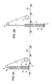
Figures 2A-2D are a series of diagrams of a longitudinal section of a portion of the device equipment depicting the different process steps; -
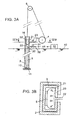
Figure 3A is a diagrammatic longitudinal section of a portion of an embodiment of a device according to the invention; -
Figure 3B is a diagrammatic transverse section along the lines III. B - III B ofFigure 3 A; and -
Figure 4 is a diagrammatic longitudinal section of a portion of the equipment and of the ground according to one process feature of the invention. - An embodiment of a not claimed device used to implement an example of a process according to the invention is shown in
Figure 1 and comprises: a frame formed by a hydraulic crane 1; a mast, column, shaft orguide 2; an insertingtube 3; supply means 4 for adrainage wick 5; and a drive member such as acable 6.Guide 2 is arranged in a generally vertical position in operating conditions. - The
guide 2 may typically comprise a hollow tube for example, which has been inserted or is insertable into the soil. Assuming that theguide 2 has been inserted into the soil, thewick inserting tube 3 may then be moved or directed through the guide or guidetube 2 to transfer thedrainage wick 5 into the soil. That is, the insertingtube 3 is moved in a downward direction through theguide tube 2 by means of a loop ofcable 6 having opposite ends attached to a fastening element attached to thetube 3. The closed loop ofcable 6 fits over the reversing driven wheel 7 at the top end of crane 1 and an idler 7A at the lower end ofguide 2. The insertingtube 3 may therefore be set into movement by rotating thecable 6 about the reversing wheel 7. Alternatively, the insertingtube 3 may be directed in a downward direction into the soil by vibration means inguide tube 2. - Further steps of the described process are shown sequentially in
Figures 2A-2D . -
Figure 2A shows the step before inserting thetube 3 into the ground: adrainage wick 5 is unwound from wick supply means 4, positioned or guided over awheel 8 and threaded through insertingtube 3. Whenlower end 51 ofdrainage wick 5 is coming out or close to thelower end 15 of insertingtube 3, one can fix a portion of a loose tie orconnector 10 at thelower end 51 ofdrainage wick 5 and another portion of saidloose tie 10 to afixation point 12, such as a ring, ofanchorage component 11. (Fig. 2-C) . - The
anchorage component 11 shown inFigure 2A is a disc which diameter is slightly larger than the maximum size of the external part of the section of insertingtube 3. - The distance between the
anchorage component 11 and thelower end 51 ofdrainage wick 5 is lower or less than the distance between the two portions of thetie 10 fixed to above mentioned parts, 51 and 12. Thus initially, theanchorage component 11 is laying on theground level 40; the drainage wicklower end 51 is situated just above it, and thelower end 15 of insertingtube 3 contacts saidanchorage component 11 so that the tie orconnector 10 is loose or unextended. -
Figure 2B illustrates the driving step ofanchorage component 11 anddrainage wick 5 downwardly into the ground with insertingtube 3. Thetie 10 remains loose. - According to an embodiment of the present invention,
loose tie 10 is kept loose thanks to a temporary bond.Drainage wick 5 andanchorage component 11 are driven downwardly into the ground by means of insertingtube 3. The strength of said temporary bond is designed as to be higher than tractive effort when driving insertingtube 3 downwardly and lower than anchorage resistance ofanchorage component 11. The temporary bond breaks when pulling up insertingtube 3. - According to another embodiment of the present invention, means are included in the device for inserting the drainage wick so that the distance between
wheel 8 andupper part 16 of insertingtube 3 remains constant when driving insertingtube 3 downwardly. No stress is applied ondrainage wick 5 nor tie 10, so thattie 10 remains loose when driving downwardly into theground inserting tube 3. - When the lowest desired position of the inserting
tube 3 is reached, the insertingtube 3 is pulled up and theanchorage component 11 is permitted to remain into the ground. Thelower end 51 of the drainage wick remains inside the insertingtube 3 up to the moment where thetie portion 10 between thelower end 51 ofdrainage wick 5 andfixation point 12 ofanchorage component 11 is completely tightened as shown inFigure 2C . The distance between lower end S ofdrainage wick 5 andfixation point 12 ofanchorage component 11 is then, for example, 1 meter. - The inserting
tube 3 is subsequently pulled up further detaching thelower end 51 fromtube 3 and theanchorage component 11 pulls ondrainage wick 5 so that bothanchorage component 11 anddrainage wick 5 are permitted to remain into the ground. - After pulling out inserting
tube 3,drainage wick 5 is cut nearground level 40 and another drainage wick can be installed. - Referring to
Figure 3A , gas, namely compressed air, may be introduced in insertingtube 3 when frictional means or retention means, such as aballoon 21, compressesdrainage wick 5 into the internal wall of insertingtube 3. Thus,valve 23 may be opened to permit pressurized air fromconduit 24 to flow throughinlet conduit 22 to expandballoon 21 from its uninflated position (20 inFigure 4 ) to its expanded position depicted inFigures 3 and4 . In the expanded position,wick 5 is fixed intube 3 and will be pulled from storage drum 4 over pulley orwheel 8 astube 8 moves into the soil. In this manner, strain onwick 5 is diminished and the bond atend 51 is maintained during placement oftube 3 into the soil. - Also, in the device of
Figure 3A , agas inlet 30 is located underballoon 21 to provide compressed air generated bycompressor 33. Atube 32 connectscompressor 33 to avalve 31.Valve 31 is opened when it is desired to introduce compressed gas into insertingtube 3 in order to pushanchorage component 11 into the ground. - Referring to
Figure 3B there is further depicted the schematic view of the mechanism which may be used to retaining thedrainage wick 5 in engagement with the interior wall of the insertingtube 3. Thus, there is depicted the external guide or guidetube 2 which receives the insertingtube 3. Thewick 5 is positioned within the insertingtube 3.Inflatable balloon 21 may be expanded from anon-engaged position 20 to an engaged position, as depicted inFigure 3B by providing compressed gas through theinlet 22. In this manner, thewick 5 will be held in a fixed position within the insertingtube 3 as thetube 3 is driven or positioned into the soil by movement within theguide 2. Thus, thewick 5 will be in position during removal of theinsertion tube 3. -
Figure 4 shows an application of the process and apparatus disclosed. The ground inFigure 4 consists of two soil layers: layer 41 is a soft soil layer andlayer 42 is a hard soil layer. - Inserting
tube 3,anchorage component 11 and the bottom ofdrainage wick 5 are driven downwardly into thehard soil layer 42, penetrating in saidhard soil layer 42 to a distance less than the length between fixation points 12, 51 oftie 10 whentie 10 is tightened. Insertingtube 3 anddrainage wick 5 are then pulled up and thebottom end 51 ofdrainage wick 5 is, as a result, located in the soft soil layer 41 above thehard soil layer 42. It is thus possible to take advantage of thehard soil layer 42 to fixanchorage component 11. - The soil around
anchorage component 11 typically rearranges when pulling up insertingtube 3 anddrainage wick 5. Asbottom end 51 ofdrainage wick 5 is located in soft soil layer, no connection betweenhard soil 42 anddrainage wick 5 can occur, since they are separated by a tie connection or connector, which is typically not water conductive. It is then possible to avoid water contamination whenhard soil 42 contains aquifer table or to allow processing vacuum soil consolidation. - The invention is not restricted to the above described embodiments which can be varied in a number of ways within the scope of the claims.
Claims (7)
- A method for inserting a drainage wick (5) into the ground comprising the steps of:- threading said drainage wick (5) through an inserting tube (3);- fixing a portion of a tie (10) to the lower end (51) of said drainage wick (5);- fixing an anchorage component (11) to another portion (12) of said tie, where said tie (10) is loose between the drainage wick lower end (51) and the anchorage component (11);- driving said anchorage component (11), said drainage wick (5) and said inserting tube (3) downwardly into the ground;- pulling up said inserting tube (3) and said drainage wick (5), whereby said anchorage component (11) is permitted to remain into said ground; and- further pulling up said inserting tube (3) whereby said anchorage component (11) and said drainage wick (5) are permitted to remain into said ground, said wick (5) being separated from said anchorage component (11); characterised in that :- the distance between the position the anchorage component (11) is permitted to remain in the soil and the position the drainage wick end (51) is permitted to remain in the soil is at least 0.10 m, and preferably no more than 2 m; and- said anchorage component (11) and said drainage wick (5) are driven downwardly into a layer of hard soil (42) situated underneath a layer of soft soil (41) and said anchorage component (11) is permitted to remain in said layer of hard soil (42) where said drainage wick (5) is permitted to remain in said layer of soft soil (41).
- A method according to claim 1 comprising the steps of:- jamming the drainage wick (5) before the inserting tube (3) is firstly pulled up;- releasing the drainage wick (5) before the inserting tube (3) is further pulled up.
- A method according to claim 2 comprising the step of introducing compressed air in said inserting tube after the drainage wick (5) jamming step.
- A method according to claim 1 comprising the steps of:- closing the lower end of said inserting tube (3) with a shutter before driving said anchorage component (11) and said drainage wick (3) downwardly into the soil- releasing said shutter before and/or when pulling up said inserting tube (3).
- A method according to claim 1 comprising the step of filling the soil zone around the anchorage component (11) with a sealing material before or when said inserting tube (3) and said drainage wick (5) are pulled up.
- A method according to claim 1 where said tie (10) is selected from the group consisting of a rope, a cord, a cable.
- A method according to claim 5 where said sealing material comprises water expandable material.
Priority Applications (1)
| Application Number | Priority Date | Filing Date | Title |
|---|---|---|---|
| PL07820730T PL2066844T3 (en) | 2006-09-28 | 2007-09-28 | Method and device for inserting a drainage wick |
Applications Claiming Priority (2)
| Application Number | Priority Date | Filing Date | Title |
|---|---|---|---|
| US11/528,755 US7566188B2 (en) | 2006-09-28 | 2006-09-28 | Method and device for inserting a drainage wick |
| PCT/EP2007/060344 WO2008037808A2 (en) | 2006-09-28 | 2007-09-28 | Method and device for inserting a drainage wick |
Publications (2)
| Publication Number | Publication Date |
|---|---|
| EP2066844A2 EP2066844A2 (en) | 2009-06-10 |
| EP2066844B1 true EP2066844B1 (en) | 2010-11-10 |
Family
ID=39015737
Family Applications (1)
| Application Number | Title | Priority Date | Filing Date |
|---|---|---|---|
| EP07820730A Not-in-force EP2066844B1 (en) | 2006-09-28 | 2007-09-28 | Method and device for inserting a drainage wick |
Country Status (9)
| Country | Link |
|---|---|
| US (1) | US7566188B2 (en) |
| EP (1) | EP2066844B1 (en) |
| AT (1) | ATE487829T1 (en) |
| AU (1) | AU2007301897B2 (en) |
| CA (1) | CA2664678C (en) |
| DE (1) | DE602007010483D1 (en) |
| ES (1) | ES2355406T3 (en) |
| PL (1) | PL2066844T3 (en) |
| WO (1) | WO2008037808A2 (en) |
Families Citing this family (5)
| Publication number | Priority date | Publication date | Assignee | Title |
|---|---|---|---|---|
| KR100839751B1 (en) * | 2008-02-01 | 2008-06-19 | 김간주 | Drain repositioning device to embed drain material in ground without anchor plate |
| SG169907A1 (en) * | 2009-09-16 | 2011-04-29 | Tok Si Entpr Co Ltd | Method and apparatus for installing prefabricated vertical drain |
| US8985898B2 (en) * | 2011-10-14 | 2015-03-24 | Dean Tomlinson | Pneumatic anchoring system for wick drains |
| CN108589692A (en) * | 2018-03-29 | 2018-09-28 | 中冶成都勘察研究总院有限公司 | A kind of novel drainage belt board-plugging device conduit device |
| US11352759B2 (en) * | 2020-08-24 | 2022-06-07 | American Piledriving Equipment, Inc. | Wick drain shoe assemblies, systems, and methods |
Family Cites Families (27)
| Publication number | Priority date | Publication date | Assignee | Title |
|---|---|---|---|---|
| US2577252A (en) | 1939-01-25 | 1951-12-04 | Kjellman Walter | Drainage method and device |
| US3396541A (en) * | 1965-04-19 | 1968-08-13 | Intrusion Prepakt Inc | Means and method for construction sand drains in the earth's surface |
| SE375570B (en) | 1972-11-27 | 1975-04-21 | Linden Alimak Ab | |
| GB1600737A (en) | 1977-03-22 | 1981-10-21 | Univ Singapore | Drainage of soils |
| JPS5934320A (en) | 1982-08-18 | 1984-02-24 | Oyo Kikaku:Kk | Dewatering work of soft ground by vertical drain material |
| PH20567A (en) | 1982-10-13 | 1987-02-18 | Kureha Chemical Ind Co Ltd | Anchor plate for drain member |
| GB2134946A (en) | 1983-02-11 | 1984-08-22 | Mauno Olavi Juhola | Means for providing a vertical drain in soil |
| US4582611A (en) * | 1984-08-09 | 1986-04-15 | Brian Watt Associates, Inc. | Soil decontamination with wick drains |
| NL8503390A (en) * | 1985-12-09 | 1987-07-01 | Nico Gerhard Cortlever | DEVICE FOR GROUNDING A DRAINAGE RIBBON. |
| JPH0621946Y2 (en) | 1986-02-17 | 1994-06-08 | 東洋建設株式会社 | Drain material holding device for board drain method |
| CZ209093A3 (en) | 1991-04-09 | 1994-04-13 | Bayer Ag | Liquid-pervious element and use thereof |
| NL9400401A (en) | 1994-03-15 | 1995-10-02 | Geotechnics Holland | Drainage Ribbon Introducing Device. |
| US5658091A (en) * | 1996-01-29 | 1997-08-19 | Geotechnics America, Inc. | Apparatus for inserting prefabricated vertical drains into the earth |
| US5800090A (en) * | 1996-04-09 | 1998-09-01 | Geotechnics America, Inc. | Apparatus and method for liquefaction remediation of liquefiable soils |
| US6254308B1 (en) | 1999-02-25 | 2001-07-03 | Menard Soltraitement | Equipment and a method for partially drying a zone of ground containing a liquid |
| US6179527B1 (en) * | 1999-04-05 | 2001-01-30 | R. Robert Goughnour | Apparatus for inserting flexible members into the earth |
| US6312190B1 (en) * | 1999-04-20 | 2001-11-06 | R. Robert Goughnour | Method and apparatus for enhancement of prefabricated composite vertical drains |
| US6766817B2 (en) | 2001-07-25 | 2004-07-27 | Tubarc Technologies, Llc | Fluid conduction utilizing a reversible unsaturated siphon with tubarc porosity action |
| NL1019619C2 (en) | 2001-12-20 | 2002-12-20 | Ndb B V | Device for placing, for example, drainage tapes. |
| EP1369533A1 (en) | 2002-06-06 | 2003-12-10 | Geotechnics Holland B.V. | Drainage material |
| EP1369534A1 (en) | 2002-06-06 | 2003-12-10 | Geotechnics Holland B.V. | Device for and method of inserting a drainage material into the ground |
| US7285255B2 (en) | 2002-12-10 | 2007-10-23 | Ecolab Inc. | Deodorizing and sanitizing employing a wicking device |
| US6846130B2 (en) * | 2003-01-28 | 2005-01-25 | Nilex Construction, Llc | Method and apparatus for enhancement of prefabricated earth drains |
| GB2402686B (en) * | 2003-04-22 | 2005-08-24 | Platipus Anchors Holdings Ltd | Ground anchor drainage apparatus and a method of installation of ground drainage apparatus |
| NL1023555C2 (en) | 2003-05-28 | 2004-12-03 | Bos & Kalis Baggermaatsch | Method and assembly for extracting or supplying substances from / to a soil body. |
| US6908259B1 (en) * | 2003-12-29 | 2005-06-21 | Nilex Construction, Llc. | Method and apparatus for remotely severing a prefabricated vertical drain |
| US7736091B2 (en) | 2006-09-28 | 2010-06-15 | Freyssinet | Method and device for inserting a drainage wick |
-
2006
- 2006-09-28 US US11/528,755 patent/US7566188B2/en not_active Expired - Fee Related
-
2007
- 2007-09-28 DE DE602007010483T patent/DE602007010483D1/en active Active
- 2007-09-28 CA CA2664678A patent/CA2664678C/en not_active Expired - Fee Related
- 2007-09-28 ES ES07820730T patent/ES2355406T3/en active Active
- 2007-09-28 EP EP07820730A patent/EP2066844B1/en not_active Not-in-force
- 2007-09-28 AT AT07820730T patent/ATE487829T1/en not_active IP Right Cessation
- 2007-09-28 WO PCT/EP2007/060344 patent/WO2008037808A2/en not_active Ceased
- 2007-09-28 PL PL07820730T patent/PL2066844T3/en unknown
- 2007-09-28 AU AU2007301897A patent/AU2007301897B2/en not_active Ceased
Also Published As
| Publication number | Publication date |
|---|---|
| ES2355406T3 (en) | 2011-03-25 |
| WO2008037808A2 (en) | 2008-04-03 |
| CA2664678C (en) | 2014-12-02 |
| WO2008037808A3 (en) | 2008-07-17 |
| EP2066844A2 (en) | 2009-06-10 |
| AU2007301897B2 (en) | 2013-01-31 |
| PL2066844T3 (en) | 2011-04-29 |
| CA2664678A1 (en) | 2008-04-03 |
| US7566188B2 (en) | 2009-07-28 |
| AU2007301897A1 (en) | 2008-04-03 |
| DE602007010483D1 (en) | 2010-12-23 |
| US20080080932A1 (en) | 2008-04-03 |
| ATE487829T1 (en) | 2010-11-15 |
Similar Documents
| Publication | Publication Date | Title |
|---|---|---|
| CA2664678C (en) | Method and device for inserting a drainage wick | |
| US11085262B2 (en) | Method of installation of a flexible borehole liner without eversion | |
| NO315169B1 (en) | Method for placing deep water pellets in the seabed | |
| US9649675B2 (en) | In-situ capping with no loss of water depth | |
| CA2664655C (en) | Method and device for inserting a drainage wick | |
| JP4282022B2 (en) | Drain pipe burial method and structures, etc. to prevent tilting, sinking or floating | |
| CN102753760A (en) | Method for the production, driving-in and injection of underwater piles | |
| KR20090130515A (en) | Ground anchoring anchor system and construction method of soft ground anchor structure using same | |
| CA2491113C (en) | Method and apparatus for remotely severing a prefabricated vertical drain | |
| KR20090130354A (en) | Pressurized index anchoring method | |
| Lee et al. | Installing piezometers in deepwater sediments | |
| JP2004197350A (en) | Construction method and structure for draining water from inside ground | |
| JP3663541B2 (en) | Impermeable mountain retaining wall with groundwater flow conservation function and its groundwater flow conservation method | |
| RU2563682C1 (en) | Vertical drainage method | |
| US8985898B2 (en) | Pneumatic anchoring system for wick drains | |
| EP2582908A2 (en) | Method and apparatus for closing or securing a well | |
| JPH08326054A (en) | Construction method of ground anchor and water stop device in drilling casing | |
| JPH0711638A (en) | Pile provided with bag | |
| KR100690396B1 (en) | Peripheral filter installation method of perforated pipe of groundwater collecting well using flexible pressure pipe | |
| JPS5934395A (en) | Method of executing pile pit | |
| EP0910709B1 (en) | Method of consolidating watery ground | |
| KR100550651B1 (en) | Casing Insertion Device of Drilling Machine | |
| KR100908283B1 (en) | Closed hole packer device that improves underwater sedimentation speed by forming channel | |
| KR200400210Y1 (en) | A apparatus for installation of Vertical drain(Beaudrain-S) | |
| KR101732015B1 (en) | PBD complex equipment installed a small scale screw structure for beforehand boring and system/method constructing PBD drain material thereof |
Legal Events
| Date | Code | Title | Description |
|---|---|---|---|
| PUAI | Public reference made under article 153(3) epc to a published international application that has entered the european phase |
Free format text: ORIGINAL CODE: 0009012 |
|
| 17P | Request for examination filed |
Effective date: 20090324 |
|
| AK | Designated contracting states |
Kind code of ref document: A2 Designated state(s): AT BE BG CH CY CZ DE DK EE ES FI FR GB GR HU IE IS IT LI LT LU LV MC MT NL PL PT RO SE SI SK TR |
|
| AX | Request for extension of the european patent |
Extension state: AL BA HR MK RS |
|
| DAX | Request for extension of the european patent (deleted) | ||
| GRAP | Despatch of communication of intention to grant a patent |
Free format text: ORIGINAL CODE: EPIDOSNIGR1 |
|
| GRAS | Grant fee paid |
Free format text: ORIGINAL CODE: EPIDOSNIGR3 |
|
| GRAA | (expected) grant |
Free format text: ORIGINAL CODE: 0009210 |
|
| AK | Designated contracting states |
Kind code of ref document: B1 Designated state(s): AT BE BG CH CY CZ DE DK EE ES FI FR GB GR HU IE IS IT LI LT LU LV MC MT NL PL PT RO SE SI SK TR |
|
| REG | Reference to a national code |
Ref country code: GB Ref legal event code: FG4D |
|
| REG | Reference to a national code |
Ref country code: CH Ref legal event code: EP |
|
| REG | Reference to a national code |
Ref country code: IE Ref legal event code: FG4D |
|
| REF | Corresponds to: |
Ref document number: 602007010483 Country of ref document: DE Date of ref document: 20101223 Kind code of ref document: P |
|
| REG | Reference to a national code |
Ref country code: NL Ref legal event code: VDEP Effective date: 20101110 |
|
| REG | Reference to a national code |
Ref country code: ES Ref legal event code: FG2A Ref document number: 2355406 Country of ref document: ES Kind code of ref document: T3 Effective date: 20110325 |
|
| LTIE | Lt: invalidation of european patent or patent extension |
Effective date: 20101110 |
|
| PG25 | Lapsed in a contracting state [announced via postgrant information from national office to epo] |
Ref country code: LT Free format text: LAPSE BECAUSE OF FAILURE TO SUBMIT A TRANSLATION OF THE DESCRIPTION OR TO PAY THE FEE WITHIN THE PRESCRIBED TIME-LIMIT Effective date: 20101110 |
|
| REG | Reference to a national code |
Ref country code: PL Ref legal event code: T3 |
|
| PG25 | Lapsed in a contracting state [announced via postgrant information from national office to epo] |
Ref country code: SI Free format text: LAPSE BECAUSE OF FAILURE TO SUBMIT A TRANSLATION OF THE DESCRIPTION OR TO PAY THE FEE WITHIN THE PRESCRIBED TIME-LIMIT Effective date: 20101110 Ref country code: FI Free format text: LAPSE BECAUSE OF FAILURE TO SUBMIT A TRANSLATION OF THE DESCRIPTION OR TO PAY THE FEE WITHIN THE PRESCRIBED TIME-LIMIT Effective date: 20101110 Ref country code: BG Free format text: LAPSE BECAUSE OF FAILURE TO SUBMIT A TRANSLATION OF THE DESCRIPTION OR TO PAY THE FEE WITHIN THE PRESCRIBED TIME-LIMIT Effective date: 20110210 Ref country code: LV Free format text: LAPSE BECAUSE OF FAILURE TO SUBMIT A TRANSLATION OF THE DESCRIPTION OR TO PAY THE FEE WITHIN THE PRESCRIBED TIME-LIMIT Effective date: 20101110 Ref country code: PT Free format text: LAPSE BECAUSE OF FAILURE TO SUBMIT A TRANSLATION OF THE DESCRIPTION OR TO PAY THE FEE WITHIN THE PRESCRIBED TIME-LIMIT Effective date: 20110310 Ref country code: NL Free format text: LAPSE BECAUSE OF FAILURE TO SUBMIT A TRANSLATION OF THE DESCRIPTION OR TO PAY THE FEE WITHIN THE PRESCRIBED TIME-LIMIT Effective date: 20101110 Ref country code: IS Free format text: LAPSE BECAUSE OF FAILURE TO SUBMIT A TRANSLATION OF THE DESCRIPTION OR TO PAY THE FEE WITHIN THE PRESCRIBED TIME-LIMIT Effective date: 20110310 Ref country code: AT Free format text: LAPSE BECAUSE OF FAILURE TO SUBMIT A TRANSLATION OF THE DESCRIPTION OR TO PAY THE FEE WITHIN THE PRESCRIBED TIME-LIMIT Effective date: 20101110 Ref country code: CY Free format text: LAPSE BECAUSE OF FAILURE TO SUBMIT A TRANSLATION OF THE DESCRIPTION OR TO PAY THE FEE WITHIN THE PRESCRIBED TIME-LIMIT Effective date: 20101110 Ref country code: SE Free format text: LAPSE BECAUSE OF FAILURE TO SUBMIT A TRANSLATION OF THE DESCRIPTION OR TO PAY THE FEE WITHIN THE PRESCRIBED TIME-LIMIT Effective date: 20101110 |
|
| PG25 | Lapsed in a contracting state [announced via postgrant information from national office to epo] |
Ref country code: GR Free format text: LAPSE BECAUSE OF FAILURE TO SUBMIT A TRANSLATION OF THE DESCRIPTION OR TO PAY THE FEE WITHIN THE PRESCRIBED TIME-LIMIT Effective date: 20110211 |
|
| PG25 | Lapsed in a contracting state [announced via postgrant information from national office to epo] |
Ref country code: BE Free format text: LAPSE BECAUSE OF FAILURE TO SUBMIT A TRANSLATION OF THE DESCRIPTION OR TO PAY THE FEE WITHIN THE PRESCRIBED TIME-LIMIT Effective date: 20101110 Ref country code: EE Free format text: LAPSE BECAUSE OF FAILURE TO SUBMIT A TRANSLATION OF THE DESCRIPTION OR TO PAY THE FEE WITHIN THE PRESCRIBED TIME-LIMIT Effective date: 20101110 Ref country code: CZ Free format text: LAPSE BECAUSE OF FAILURE TO SUBMIT A TRANSLATION OF THE DESCRIPTION OR TO PAY THE FEE WITHIN THE PRESCRIBED TIME-LIMIT Effective date: 20101110 |
|
| PG25 | Lapsed in a contracting state [announced via postgrant information from national office to epo] |
Ref country code: RO Free format text: LAPSE BECAUSE OF FAILURE TO SUBMIT A TRANSLATION OF THE DESCRIPTION OR TO PAY THE FEE WITHIN THE PRESCRIBED TIME-LIMIT Effective date: 20101110 Ref country code: DK Free format text: LAPSE BECAUSE OF FAILURE TO SUBMIT A TRANSLATION OF THE DESCRIPTION OR TO PAY THE FEE WITHIN THE PRESCRIBED TIME-LIMIT Effective date: 20101110 Ref country code: SK Free format text: LAPSE BECAUSE OF FAILURE TO SUBMIT A TRANSLATION OF THE DESCRIPTION OR TO PAY THE FEE WITHIN THE PRESCRIBED TIME-LIMIT Effective date: 20101110 |
|
| PLBE | No opposition filed within time limit |
Free format text: ORIGINAL CODE: 0009261 |
|
| STAA | Information on the status of an ep patent application or granted ep patent |
Free format text: STATUS: NO OPPOSITION FILED WITHIN TIME LIMIT |
|
| 26N | No opposition filed |
Effective date: 20110811 |
|
| REG | Reference to a national code |
Ref country code: DE Ref legal event code: R097 Ref document number: 602007010483 Country of ref document: DE Effective date: 20110811 |
|
| PG25 | Lapsed in a contracting state [announced via postgrant information from national office to epo] |
Ref country code: IT Free format text: LAPSE BECAUSE OF FAILURE TO SUBMIT A TRANSLATION OF THE DESCRIPTION OR TO PAY THE FEE WITHIN THE PRESCRIBED TIME-LIMIT Effective date: 20101110 |
|
| PG25 | Lapsed in a contracting state [announced via postgrant information from national office to epo] |
Ref country code: MC Free format text: LAPSE BECAUSE OF NON-PAYMENT OF DUE FEES Effective date: 20110930 |
|
| REG | Reference to a national code |
Ref country code: CH Ref legal event code: PL |
|
| REG | Reference to a national code |
Ref country code: IE Ref legal event code: MM4A |
|
| PG25 | Lapsed in a contracting state [announced via postgrant information from national office to epo] |
Ref country code: LI Free format text: LAPSE BECAUSE OF NON-PAYMENT OF DUE FEES Effective date: 20110930 Ref country code: IE Free format text: LAPSE BECAUSE OF NON-PAYMENT OF DUE FEES Effective date: 20110928 Ref country code: CH Free format text: LAPSE BECAUSE OF NON-PAYMENT OF DUE FEES Effective date: 20110930 |
|
| PG25 | Lapsed in a contracting state [announced via postgrant information from national office to epo] |
Ref country code: MT Free format text: LAPSE BECAUSE OF FAILURE TO SUBMIT A TRANSLATION OF THE DESCRIPTION OR TO PAY THE FEE WITHIN THE PRESCRIBED TIME-LIMIT Effective date: 20101110 |
|
| PG25 | Lapsed in a contracting state [announced via postgrant information from national office to epo] |
Ref country code: LU Free format text: LAPSE BECAUSE OF NON-PAYMENT OF DUE FEES Effective date: 20110928 |
|
| PG25 | Lapsed in a contracting state [announced via postgrant information from national office to epo] |
Ref country code: TR Free format text: LAPSE BECAUSE OF FAILURE TO SUBMIT A TRANSLATION OF THE DESCRIPTION OR TO PAY THE FEE WITHIN THE PRESCRIBED TIME-LIMIT Effective date: 20101110 |
|
| PG25 | Lapsed in a contracting state [announced via postgrant information from national office to epo] |
Ref country code: HU Free format text: LAPSE BECAUSE OF FAILURE TO SUBMIT A TRANSLATION OF THE DESCRIPTION OR TO PAY THE FEE WITHIN THE PRESCRIBED TIME-LIMIT Effective date: 20101110 |
|
| REG | Reference to a national code |
Ref country code: FR Ref legal event code: CA Effective date: 20150112 |
|
| REG | Reference to a national code |
Ref country code: FR Ref legal event code: PLFP Year of fee payment: 9 |
|
| REG | Reference to a national code |
Ref country code: FR Ref legal event code: PLFP Year of fee payment: 10 |
|
| REG | Reference to a national code |
Ref country code: FR Ref legal event code: PLFP Year of fee payment: 11 |
|
| REG | Reference to a national code |
Ref country code: FR Ref legal event code: PLFP Year of fee payment: 12 |
|
| PGFP | Annual fee paid to national office [announced via postgrant information from national office to epo] |
Ref country code: DE Payment date: 20180821 Year of fee payment: 12 Ref country code: FR Payment date: 20180822 Year of fee payment: 12 |
|
| PGFP | Annual fee paid to national office [announced via postgrant information from national office to epo] |
Ref country code: GB Payment date: 20180823 Year of fee payment: 12 Ref country code: PL Payment date: 20180823 Year of fee payment: 12 |
|
| PGFP | Annual fee paid to national office [announced via postgrant information from national office to epo] |
Ref country code: ES Payment date: 20181001 Year of fee payment: 12 |
|
| REG | Reference to a national code |
Ref country code: DE Ref legal event code: R119 Ref document number: 602007010483 Country of ref document: DE |
|
| PG25 | Lapsed in a contracting state [announced via postgrant information from national office to epo] |
Ref country code: DE Free format text: LAPSE BECAUSE OF NON-PAYMENT OF DUE FEES Effective date: 20200401 |
|
| GBPC | Gb: european patent ceased through non-payment of renewal fee |
Effective date: 20190928 |
|
| PG25 | Lapsed in a contracting state [announced via postgrant information from national office to epo] |
Ref country code: GB Free format text: LAPSE BECAUSE OF NON-PAYMENT OF DUE FEES Effective date: 20190928 Ref country code: FR Free format text: LAPSE BECAUSE OF NON-PAYMENT OF DUE FEES Effective date: 20190930 |
|
| REG | Reference to a national code |
Ref country code: ES Ref legal event code: FD2A Effective date: 20210201 |
|
| PG25 | Lapsed in a contracting state [announced via postgrant information from national office to epo] |
Ref country code: ES Free format text: LAPSE BECAUSE OF NON-PAYMENT OF DUE FEES Effective date: 20190929 |
|
| PG25 | Lapsed in a contracting state [announced via postgrant information from national office to epo] |
Ref country code: PL Free format text: LAPSE BECAUSE OF NON-PAYMENT OF DUE FEES Effective date: 20190928 |