EP2066242B1 - Système de compression et de distraction percutané - Google Patents
Système de compression et de distraction percutané Download PDFInfo
- Publication number
- EP2066242B1 EP2066242B1 EP07838793A EP07838793A EP2066242B1 EP 2066242 B1 EP2066242 B1 EP 2066242B1 EP 07838793 A EP07838793 A EP 07838793A EP 07838793 A EP07838793 A EP 07838793A EP 2066242 B1 EP2066242 B1 EP 2066242B1
- Authority
- EP
- European Patent Office
- Prior art keywords
- shaft
- distraction
- tip
- compression
- pliers
- Prior art date
- Legal status (The legal status is an assumption and is not a legal conclusion. Google has not performed a legal analysis and makes no representation as to the accuracy of the status listed.)
- Active
Links
- 230000006835 compression Effects 0.000 title claims abstract description 74
- 238000007906 compression Methods 0.000 title claims abstract description 74
- 210000000988 bone and bone Anatomy 0.000 claims abstract description 27
- 239000011521 glass Substances 0.000 abstract description 6
- 230000000712 assembly Effects 0.000 description 5
- 238000000429 assembly Methods 0.000 description 5
- 238000000034 method Methods 0.000 description 4
- 238000010276 construction Methods 0.000 description 3
- 238000004873 anchoring Methods 0.000 description 2
- 238000002324 minimally invasive surgery Methods 0.000 description 2
- 239000004606 Fillers/Extenders Substances 0.000 description 1
- 230000015572 biosynthetic process Effects 0.000 description 1
- 238000012986 modification Methods 0.000 description 1
- 230000004048 modification Effects 0.000 description 1
- 238000000926 separation method Methods 0.000 description 1
- 239000003381 stabilizer Substances 0.000 description 1
Images


Classifications
-
- A—HUMAN NECESSITIES
- A61—MEDICAL OR VETERINARY SCIENCE; HYGIENE
- A61B—DIAGNOSIS; SURGERY; IDENTIFICATION
- A61B17/00—Surgical instruments, devices or methods, e.g. tourniquets
- A61B17/02—Surgical instruments, devices or methods, e.g. tourniquets for holding wounds open; Tractors
- A61B17/025—Joint distractors
-
- A—HUMAN NECESSITIES
- A61—MEDICAL OR VETERINARY SCIENCE; HYGIENE
- A61B—DIAGNOSIS; SURGERY; IDENTIFICATION
- A61B17/00—Surgical instruments, devices or methods, e.g. tourniquets
- A61B17/56—Surgical instruments or methods for treatment of bones or joints; Devices specially adapted therefor
- A61B17/58—Surgical instruments or methods for treatment of bones or joints; Devices specially adapted therefor for osteosynthesis, e.g. bone plates, screws, setting implements or the like
- A61B17/68—Internal fixation devices, including fasteners and spinal fixators, even if a part thereof projects from the skin
- A61B17/70—Spinal positioners or stabilisers ; Bone stabilisers comprising fluid filler in an implant
- A61B17/7001—Screws or hooks combined with longitudinal elements which do not contact vertebrae
-
- A—HUMAN NECESSITIES
- A61—MEDICAL OR VETERINARY SCIENCE; HYGIENE
- A61B—DIAGNOSIS; SURGERY; IDENTIFICATION
- A61B17/00—Surgical instruments, devices or methods, e.g. tourniquets
- A61B17/56—Surgical instruments or methods for treatment of bones or joints; Devices specially adapted therefor
- A61B17/58—Surgical instruments or methods for treatment of bones or joints; Devices specially adapted therefor for osteosynthesis, e.g. bone plates, screws, setting implements or the like
- A61B17/68—Internal fixation devices, including fasteners and spinal fixators, even if a part thereof projects from the skin
- A61B17/70—Spinal positioners or stabilisers ; Bone stabilisers comprising fluid filler in an implant
- A61B17/7074—Tools specially adapted for spinal fixation operations other than for bone removal or filler handling
- A61B17/7076—Tools specially adapted for spinal fixation operations other than for bone removal or filler handling for driving, positioning or assembling spinal clamps or bone anchors specially adapted for spinal fixation
- A61B17/7077—Tools specially adapted for spinal fixation operations other than for bone removal or filler handling for driving, positioning or assembling spinal clamps or bone anchors specially adapted for spinal fixation for moving bone anchors attached to vertebrae, thereby displacing the vertebrae
- A61B17/7079—Tools requiring anchors to be already mounted on an implanted longitudinal or transverse element, e.g. where said element guides the anchor motion
-
- A—HUMAN NECESSITIES
- A61—MEDICAL OR VETERINARY SCIENCE; HYGIENE
- A61B—DIAGNOSIS; SURGERY; IDENTIFICATION
- A61B17/00—Surgical instruments, devices or methods, e.g. tourniquets
- A61B17/02—Surgical instruments, devices or methods, e.g. tourniquets for holding wounds open; Tractors
- A61B17/025—Joint distractors
- A61B2017/0256—Joint distractors for the spine
Definitions
- the present invention relates to a percutaneous compression and distraction system, more particularly to a system for percutaneous compression, or distraction of vertebral bodies via pedicle screws.
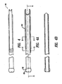
- Figure 2 is a side view of the shaft of Figure 1 .
- Figure 2B is a sectional view along line A-A of shaft of Figure 1 .
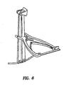
- Figure 6A also shows distraction pliers engaged with compression distraction shafts.
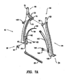
- Figure 7A shows details of the distraction pliers assembly of Figure 7 .
- Figure 8A shows details of the compression pliers assembly of Figure 8 .
- Assembly 20 includes a shaft 26.
- Figure 2 shows the details of construction of shaft 26.
- Shaft 26 has two long plates 28 attached to it in diametrically opposed location. One end of each of the plates 28 overhangs from the first end 30 of shaft 26. The overhanging portions are located opposite each other and have an arcuate shape at the very tip. The arcuate shape allows shaft 26 to lay over a rod that may be implanted on the vertebrae.
- Figures 8 and 8A show compression pliers 110.
- Compression pliers 110 have a third handle 112 and a fourth handle 114.
- Third handle 112 has a tip end 116 and a ratchet end 118.
- a cylindrical tip 120 is formed at tip end 116.
- a hole 122 is formed in the body of third handle 112 below tip end 116.
- the end of third handle 112 opposing tip end 116 has two tabs 124 and 126.
- a bore 128 is formed through tabs 124 and 126.
- a screw hole 130 is formed in body of third handle 112 above tabs 124 and 126.
- a leaf spring 132 is attached to third handle 112 by inserting a screw 134 in a hole 136 formed in leaf spring 132 and threading the screw in the hole 130.
- leaf springs 132 and 154 When engaged, leaf springs 132 and 154 keep the compression pliers biased in an open position.
- a tooth 162 is formed at the tip of ratchet end 148.
- Third handle 112 and fourth handle 114 are rotatably joined together by aligning bores 122 and 152 and inserting a screw 164 through them.
- cylindrical tips 120 and 150 are inserted in hour glass shaped bores 34 and 54 and third handle 112 and fourth handle 114 pressed together.
- cylindrical tips 120 and 150 are moved towards each other. This results in compression of the vertebrae that are connected to the arcuate shaped end of the shaft assembly 20 and shaft assembly 22.
- the connection between the arcuate end of the shaft assemblies 20 and 22 and the vertebrae may be made in any known manner.
- each of the shaft assemblies 20 and 22 may be connected to a cup of a pedicle screw mounted on the vertebrae via a latch or a threaded connection.
Landscapes
- Health & Medical Sciences (AREA)
- Orthopedic Medicine & Surgery (AREA)
- Neurology (AREA)
- Life Sciences & Earth Sciences (AREA)
- Surgery (AREA)
- Heart & Thoracic Surgery (AREA)
- Engineering & Computer Science (AREA)
- Biomedical Technology (AREA)
- Nuclear Medicine, Radiotherapy & Molecular Imaging (AREA)
- Medical Informatics (AREA)
- Molecular Biology (AREA)
- Animal Behavior & Ethology (AREA)
- General Health & Medical Sciences (AREA)
- Public Health (AREA)
- Veterinary Medicine (AREA)
- Surgical Instruments (AREA)
- Prostheses (AREA)
Abstract
Claims (13)
- Système de compression d'os, comprenant une première tige (26) ayant un premier bout (36) et une deuxième tige (44) ayant un deuxième bout (48), où la première tige est adaptée pour contacter une attache à un premier os et la deuxième tige est adaptée pour contacter une attache à un deuxième os ; caractérisé en ce que le système de compression d'os comprend aussi une pince de compression (110) pour comprimer l'un vers l'autre la première tige (26) et la deuxième tige (44), où le premier bout (36) de la première tige (26) et le deuxième bout (48) de la deuxième tige (44) sont adaptés pour se joindre pour créer un centre de pivotement polyaxial autour duquel la première tige (26) et la deuxième tige (44) sont articulées, où la pince de compression (110) contacte la première tige (26) et la deuxième tige (44) telle que le mouvement du centre de pivotement polyaxial n'est pas restreint par la pince de compression (110).
- Système de compression d'os selon la revendication 1, comprenant aussi un clip (38) en forme d'un « U » attaché au premier bout (36) de la première tige (26), où le clip (38) en forme d'un « U » est capable de recevoir le deuxième bout (48) de la deuxième tige (44) pour former le centre de pivotement polyaxial.
- Système de compression d'os selon la revendication 2, comprenant aussi- une première poignée (112), qui comprend une première pointe (120) et qui est connecté pour un pivotement avec une deuxième poignée (114), qui a une deuxième pointe (150), où la première pointe (120) et la deuxième pointe (150) sont cylindriques, où la première et la deuxième poignée forment une pince de compression (110), et- une première ouverture (34) qui est formée sur la première tige (26), et une deuxième ouverture (54) qui est formée sur la deuxième tige (44), où les premières et deuxièmes ouvertures sont adaptées pour recevoir l'un ou l'autre de la première pointe (120) et de la deuxième pointe (150), telles que, si aussi bien la première pointe (120) et la deuxième pointe (150) sont insérées dans la première et la deuxième ouverture, le mouvement de la première tige (26) et de la deuxième tige (44) n'est pas restreint par la pince de compression (110).
- Système de compression d'os selon la revendication 3, où la première ouverture (34) et la deuxième ouverture (54) sont formées comme un sablier.
- Système de distraction d'os, comprenant une première tige (26) ayant un premier bout (36) et une deuxième tige (44) ayant un deuxième bout (48), où la première tige est adaptée pour contacter une attache à un premier os et la deuxième tige est adaptée pour contacter une attache à un deuxième os ; caractérisé en ce que le système de distraction d'os comprend aussi une pince de distraction (60) pour éloigner la première tige (26) de la deuxième tige (44), où le premier bout (36) de la première tige (26) et le deuxième bout (48) de la deuxième tige (44) sont adaptés pour se joindre pour créer un centre de pivotement polyaxial autour duquel la première tige (26) et la deuxième tige (44) sont articulées, où la pince de distraction (60) contacte la première tige (26) et la deuxième tige (44) telle que le mouvement du centre de pivotement polyaxial n'est pas restreint par la pince de distraction (60).
- Système de distraction d'os selon la revendication 5, comprenant aussi un clip (38) en forme d'un « U » attaché au premier bout (36) de la première tige (26), où le clip (38) en forme d'un « U » est capable de recevoir le deuxième bout (48) de la deuxième tige (44) pour former le centre de pivotement polyaxial.
- Système de distraction d'os selon la revendication 5, comprenant aussi- une première poignée (62), qui comprend une première pointe (70) et qui est connecté pour un pivotement avec une deuxième poignée (64), qui a une deuxième pointe (90), où la première pointe (70) et la deuxième pointe (90) sont cylindriques, où la première et la deuxième poignée forment une pince de distraction (60), et- une première ouverture (34) qui est formée sur la première tige (26), et une deuxième ouverture (54) qui est formée sur la deuxième tige (44), où les premières et deuxièmes ouvertures sont adaptées pour recevoir l'un ou l'autre de la première pointe (70) et de la deuxième pointe (90), telles que, si aussi bien la première pointe (70) et la deuxième pointe (90) sont insérées dans la première et la deuxième ouverture, le mouvement de la première tige (26) et de la deuxième tige (44) n'est pas restreint par la pince de distraction (60).
- Système de distraction d'os selon la revendication 7, où la première ouverture (34) et la deuxième ouverture (54) sont formées comme un sablier.
- Système de compression et de distraction selon la revendication 1, comprenant aussi une pince de distraction (60) pour éloigner la première tige (26) et la deuxième tige (44), où la pince de distraction (60) contacte la première tige (26) et la deuxième tige (44) telle que le mouvement du centre de pivotement polyaxial n'est pas restreint par la pince de distraction (60).
- Système de compression et de distraction selon la revendication 9, comprenant aussi un clip (38) en forme d'un « U » attaché au premier bout (36) de la première tige (26), et une bille essentiellement sphérique (56) formée au deuxième bout (48) de la deuxième tige (44), où le clip (38) en forme d'un « U » est capable de recevoir le deuxième bout (48) de la deuxième tige (44) pour former le centre de pivotement polyaxial.
- Système de compression et de distraction selon la revendication 10, où une première ouverture (34) est formée sur la première tige (26) ; et une deuxième ouverture (54) est formée sur la deuxième tige (44), où les première et deuxième ouvertures sont formées comme un sablier.
- Système de compression et de distraction selon la revendication 11, comprenant aussi- une première poignée (62), qui comprend une première pointe (70) et qui est connecté pour un pivotement avec une deuxième poignée (64), qui a une deuxième pointe (70), où la première pointe (70) et la deuxième pointe (90) sont cylindriques, où la première et la deuxième poignée forment une pince de distraction (60), où- la première pointe (70) et la deuxième pointe (90) sont adaptées pour être reçues dans la première et la deuxième ouverture, telles que, si aussi bien la première pointe (70) et la deuxième pointe (90) sont insérées dans la première et la deuxième ouverture, le mouvement de la première tige (26) et de la deuxième tige (44) n'est pas restreint par la pince de distraction (60).
- Système de compression et de distraction selon la revendication 11, comprenant aussi- une première poignée (112), qui comprend une première pointe (120) et qui est connecté pour un pivotement avec une deuxième poignée (114), qui a une deuxième pointe (150), où la première pointe (120) et la deuxième pointe (150) sont cylindriques, où la première et la deuxième poignée forment une pince de compression (110), où- la première pointe (120) et la deuxième pointe (150) sont adaptées pour être reçues dans la première et la deuxième ouverture, telles que, si aussi bien la première pointe (120) et la deuxième pointe (150) sont insérées dans la première et la deuxième ouverture, le mouvement de la première tige (26) et de la deuxième tige (44) n'est pas restreint par la pince de compression (110).
Applications Claiming Priority (2)
| Application Number | Priority Date | Filing Date | Title |
|---|---|---|---|
| US84717406P | 2006-09-25 | 2006-09-25 | |
| PCT/US2007/020660 WO2008039447A1 (fr) | 2006-09-25 | 2007-09-25 | système de compression et de distraction percutané |
Publications (2)
| Publication Number | Publication Date |
|---|---|
| EP2066242A1 EP2066242A1 (fr) | 2009-06-10 |
| EP2066242B1 true EP2066242B1 (fr) | 2011-05-04 |
Family
ID=38869782
Family Applications (1)
| Application Number | Title | Priority Date | Filing Date |
|---|---|---|---|
| EP07838793A Active EP2066242B1 (fr) | 2006-09-25 | 2007-09-25 | Système de compression et de distraction percutané |
Country Status (4)
| Country | Link |
|---|---|
| US (7) | US8157809B2 (fr) |
| EP (1) | EP2066242B1 (fr) |
| DE (1) | DE602007014385D1 (fr) |
| WO (1) | WO2008039447A1 (fr) |
Cited By (1)
| Publication number | Priority date | Publication date | Assignee | Title |
|---|---|---|---|---|
| RU227005U1 (ru) * | 2023-10-30 | 2024-07-01 | федеральное государственное бюджетное учреждение "Национальный медицинский исследовательский центр детской травматологии и ортопедии имени Г.И. Турнера" Министерства здравоохранения Российской Федерации | Блок динамометрический для контракции и дистракции при хирургическом лечении деформаций позвоночника |
Families Citing this family (25)
| Publication number | Priority date | Publication date | Assignee | Title |
|---|---|---|---|---|
| US7955355B2 (en) | 2003-09-24 | 2011-06-07 | Stryker Spine | Methods and devices for improving percutaneous access in minimally invasive surgeries |
| US9011447B2 (en) | 2006-09-25 | 2015-04-21 | Stryker Spine | Rod contouring alignment linkage |
| WO2008144000A1 (fr) * | 2007-05-18 | 2008-11-27 | Stryker Spine | Appareil et procédé de rotation vertébrale directe |
| US9907582B1 (en) | 2011-04-25 | 2018-03-06 | Nuvasive, Inc. | Minimally invasive spinal fixation system and related methods |
| US9125703B2 (en) | 2012-01-16 | 2015-09-08 | K2M, Inc. | Rod reducer, compressor, distractor system |
| US8951258B2 (en) | 2013-03-01 | 2015-02-10 | Warsaw Orthopedic, Inc. | Spinal correction system and method |
| US9827020B2 (en) | 2013-03-14 | 2017-11-28 | Stryker European Holdings I, Llc | Percutaneous spinal cross link system and method |
| US9510875B2 (en) | 2013-03-14 | 2016-12-06 | Stryker European Holdings I, Llc | Systems and methods for percutaneous spinal fusion |
| US9744050B1 (en) | 2013-12-06 | 2017-08-29 | Stryker European Holdings I, Llc | Compression and distraction system for percutaneous posterior spinal fusion |
| US10159579B1 (en) | 2013-12-06 | 2018-12-25 | Stryker European Holdings I, Llc | Tubular instruments for percutaneous posterior spinal fusion systems and methods |
| US9408716B1 (en) | 2013-12-06 | 2016-08-09 | Stryker European Holdings I, Llc | Percutaneous posterior spinal fusion implant construction and method |
| CA2874390C (fr) | 2013-12-13 | 2018-03-06 | Stryker European Holdings I, Llc | Dispositifs, systemes et procedes de retraction tissulaire et de deplacement vertebral pour fusion spinale posterieure |
| CN105720036A (zh) * | 2014-12-03 | 2016-06-29 | 恒劲科技股份有限公司 | 封装结构及其制法 |
| US10034690B2 (en) | 2014-12-09 | 2018-07-31 | John A. Heflin | Spine alignment system |
| US10194960B1 (en) | 2015-12-03 | 2019-02-05 | Nuvasive, Inc. | Spinal compression instrument and related methods |
| WO2017109540A1 (fr) | 2015-12-21 | 2017-06-29 | Arcelormittal | Procédé de fabrication d'une tôle d'acier à haute résistance ayant une ductilité et une aptitude au formage améliorées et tôle d'acier ainsi obtenue |
| US10617449B2 (en) | 2016-01-08 | 2020-04-14 | Stryker European Holdings I, Llc | Tap marker |
| US10779866B2 (en) | 2016-12-29 | 2020-09-22 | K2M, Inc. | Rod reducer assembly |
| US10736672B2 (en) | 2017-05-25 | 2020-08-11 | Warsaw Orthopedic, Inc. | Spinal implant system and method |
| ES2871543T3 (es) * | 2018-01-26 | 2021-10-29 | Aesculap Ag | Instrumento de reposicionamiento espinal y sistema de reposicionamiento espinal |
| US10285742B1 (en) | 2018-06-22 | 2019-05-14 | Avanti Orthopaedics Llc | Bone manipulator system and method |
| EP3669801B1 (fr) | 2018-12-21 | 2024-03-06 | Stryker European Operations Limited | Taraud et marqueur combinés à extension flexible et instruments associés |
| US11382671B2 (en) | 2019-06-25 | 2022-07-12 | Warsaw Orthopedic, Inc. | Surgical instrument and method |
| US11350922B1 (en) | 2021-02-03 | 2022-06-07 | Warsaw Orthopedic, Inc. | Modular surgical instrument system and method for shank-based retraction and distraction |
| US11432852B1 (en) | 2021-03-22 | 2022-09-06 | Warsaw Orthopedic, Inc. | Screw shank based tissue retraction |
Family Cites Families (52)
| Publication number | Priority date | Publication date | Assignee | Title |
|---|---|---|---|---|
| GB1519139A (en) | 1974-06-18 | 1978-07-26 | Crock H V And Pericic L | L securing elongate members to structurs more especially in surgical procedures |
| CH639264A5 (en) | 1979-09-11 | 1983-11-15 | Synthes Ag | Instrument used for the treatment of vertebral fractures and scoliosis |
| SU839513A1 (ru) | 1979-09-14 | 1981-06-23 | Центральный Ордена Трудовогокрасного Знамени Научно-Исследова-Тельский Институт Травматологии Иортопедии Им. H.H.Приорова | Устройство дл проведени спиц |
| US4409968A (en) | 1980-02-04 | 1983-10-18 | Drummond Denis S | Method and apparatus for engaging a hook assembly to a spinal column |
| US4411259A (en) | 1980-02-04 | 1983-10-25 | Drummond Denis S | Apparatus for engaging a hook assembly to a spinal column |
| DE3711091A1 (de) | 1987-04-02 | 1988-10-13 | Kluger Patrick | Vorrichtung zum einrichten einer wirbelsaeule mit geschaedigten wirbelkoerpern |
| USRE36221E (en) | 1989-02-03 | 1999-06-01 | Breard; Francis Henri | Flexible inter-vertebral stabilizer as well as process and apparatus for determining or verifying its tension before installation on the spinal column |
| JPH0620466B2 (ja) | 1989-03-31 | 1994-03-23 | 有限会社田中医科器械製作所 | 脊柱変形矯正固定装置 |
| US5059194A (en) | 1990-02-12 | 1991-10-22 | Michelson Gary K | Cervical distractor |
| US5545228A (en) | 1991-08-15 | 1996-08-13 | Smith & Nephew Richards Inc. | Offset bone bolt |
| US5584887A (en) | 1991-08-15 | 1996-12-17 | Smith & Nephew Richards, Inc. | Percutaneous screw adapter |
| US5242443A (en) | 1991-08-15 | 1993-09-07 | Smith & Nephew Dyonics, Inc. | Percutaneous fixation of vertebrae |
| DE4127303A1 (de) | 1991-08-17 | 1993-02-18 | Aesculap Ag | Fixateur interne zur reposition einer lumbalen spondylolisthesis |
| US5167662A (en) * | 1992-01-24 | 1992-12-01 | Zimmer, Inc. | Temporary clamp and inserter for a posterior midline spinal clamp |
| DE4202748A1 (de) | 1992-01-31 | 1993-08-05 | Kluger Patrick | Wirbelsaeulenimplantat und -repositionsinstrumente |
| US5281223A (en) | 1992-09-21 | 1994-01-25 | Ray R Charles | Tool and method for derotating scoliotic spine |
| US5487743A (en) | 1994-02-15 | 1996-01-30 | Sofamore, S.N.C. | Anterior dorso-lumbar spinal osteosynthesis instrumentation for the correction of kyphosis |
| FR2757761B1 (fr) * | 1996-12-27 | 1999-08-20 | Stryker France Sa | Systeme d'oteosynthese du rachis avec reglage en position |
| ATE380511T1 (de) | 1997-02-11 | 2007-12-15 | Warsaw Orthopedic Inc | Platte für die vordere halswirbelsäule mit fixierungssystem für eine schraube |
| DE29710979U1 (de) | 1997-06-24 | 1997-08-21 | Aesculap AG & Co. KG, 78532 Tuttlingen | Implantat zur Fixierung von Knochenteilen und Werkzeug für dieses Implantat |
| US6241729B1 (en) | 1998-04-09 | 2001-06-05 | Sdgi Holdings, Inc. | Method and instrumentation for posterior interbody fusion |
| US6123707A (en) | 1999-01-13 | 2000-09-26 | Spinal Concepts, Inc. | Reduction instrument |
| US6146386A (en) | 1999-02-04 | 2000-11-14 | Sdgi Holdings, Inc. | Cable operated bone anchor compressor |
| US6770096B2 (en) | 1999-07-01 | 2004-08-03 | Spinevision S.A. | Interbody spinal stabilization cage and spinal stabilization method |
| US6530929B1 (en) | 1999-10-20 | 2003-03-11 | Sdgi Holdings, Inc. | Instruments for stabilization of bony structures |
| ATE275877T1 (de) | 1999-11-25 | 2004-10-15 | Ct Pulse Orthopedics Ltd | Chirurgisches instrument zum spannen eines kabelartigen spannelements |
| WO2001041681A1 (fr) | 1999-12-10 | 2001-06-14 | Nuvasive, Inc. | Vis a facette et systeme de support et de fusion intervertebraux avec allogreffes osseuses |
| DE10027988C2 (de) | 2000-06-06 | 2003-08-21 | Arkadiusz Kosmala | Vorrichtung zur stereotaktisch geführten perkutanen Implantation der Längsverbindung der Pedikelschrauben |
| US7056321B2 (en) | 2000-08-01 | 2006-06-06 | Endius, Incorporated | Method of securing vertebrae |
| US7985247B2 (en) | 2000-08-01 | 2011-07-26 | Zimmer Spine, Inc. | Methods and apparatuses for treating the spine through an access device |
| US6802844B2 (en) | 2001-03-26 | 2004-10-12 | Nuvasive, Inc | Spinal alignment apparatus and methods |
| US6648891B2 (en) | 2001-09-14 | 2003-11-18 | The Regents Of The University Of California | System and method for fusing spinal vertebrae |
| US7052497B2 (en) | 2002-08-14 | 2006-05-30 | Sdgi Holdings, Inc. | Techniques for spinal surgery and attaching constructs to vertebral elements |
| AU2002323586A1 (en) | 2002-09-05 | 2004-03-29 | Endius Incorporated | System and methods for performing minimally-invasive surgical procedures |
| US20040147928A1 (en) | 2002-10-30 | 2004-07-29 | Landry Michael E. | Spinal stabilization system using flexible members |
| US20040172022A1 (en) | 2002-10-30 | 2004-09-02 | Landry Michael E. | Bone fastener assembly for a spinal stabilization system |
| US7608096B2 (en) | 2003-03-10 | 2009-10-27 | Warsaw Orthopedic, Inc. | Posterior pedicle screw and plate system and methods |
| ATE322219T1 (de) | 2003-04-24 | 2006-04-15 | Zimmer Gmbh | Instrumentensystem für pedikelschrauben |
| US7473267B2 (en) | 2003-04-25 | 2009-01-06 | Warsaw Orthopedic, Inc. | System and method for minimally invasive posterior fixation |
| US6945974B2 (en) | 2003-07-07 | 2005-09-20 | Aesculap Inc. | Spinal stabilization implant and method of application |
| US7976464B2 (en) | 2003-08-26 | 2011-07-12 | Zimmer Spine, Inc. | Access systems and methods for minimally invasive surgery |
| US7455685B2 (en) | 2003-09-29 | 2008-11-25 | Warsaw Orthopedic, Inc. | Instruments and methods for securing a connecting element along a bony segment |
| WO2005032358A2 (fr) | 2003-10-02 | 2005-04-14 | Endius, Inc. | Procedes, systemes et appareils permettant de realiser des operations de la colonne vertebrale tres peu invasives |
| US7731737B2 (en) | 2003-10-24 | 2010-06-08 | Zimmer Spine, Inc. | Methods and apparatuses for fixation of the spine through an access device |
| US20050090822A1 (en) | 2003-10-24 | 2005-04-28 | Dipoto Gene | Methods and apparatus for stabilizing the spine through an access device |
| US7666188B2 (en) * | 2003-12-16 | 2010-02-23 | Depuy Spine, Inc. | Methods and devices for spinal fixation element placement |
| AU2004304934B2 (en) | 2003-12-16 | 2008-10-16 | Depuy Spine, Inc. | Methods and devices for minimally invasive spinal fixation element placement |
| US7527638B2 (en) | 2003-12-16 | 2009-05-05 | Depuy Spine, Inc. | Methods and devices for minimally invasive spinal fixation element placement |
| US7776051B2 (en) | 2004-05-03 | 2010-08-17 | Theken Spine, Llc | System and method for displacement of bony structures |
| US7811288B2 (en) | 2004-12-02 | 2010-10-12 | Zimmer Spine, Inc. | Instruments and methods for adjusting separation distance of vertebral bodies with a minimally invasive spinal stabilization procedure |
| US8177817B2 (en) | 2005-05-18 | 2012-05-15 | Stryker Spine | System and method for orthopedic implant configuration |
| CA2637684C (fr) | 2006-02-06 | 2011-09-13 | Stryker Spine | Appareil de contournage de tringle et methode d'extension a vis de pedicule percutanee |
-
2007
- 2007-09-25 WO PCT/US2007/020660 patent/WO2008039447A1/fr active Application Filing
- 2007-09-25 US US11/904,030 patent/US8157809B2/en active Active
- 2007-09-25 EP EP07838793A patent/EP2066242B1/fr active Active
- 2007-09-25 DE DE602007014385T patent/DE602007014385D1/de active Active
-
2012
- 2012-03-14 US US13/419,919 patent/US8506574B2/en active Active
-
2013
- 2013-07-15 US US13/942,071 patent/US8915925B2/en active Active
-
2014
- 2014-11-19 US US14/547,482 patent/US9345463B2/en active Active
-
2016
- 2016-04-28 US US15/141,238 patent/US10470752B2/en active Active
-
2019
- 2019-10-24 US US16/662,515 patent/US11523810B2/en active Active
-
2022
- 2022-11-18 US US17/990,033 patent/US20230082047A1/en active Pending
Cited By (1)
| Publication number | Priority date | Publication date | Assignee | Title |
|---|---|---|---|---|
| RU227005U1 (ru) * | 2023-10-30 | 2024-07-01 | федеральное государственное бюджетное учреждение "Национальный медицинский исследовательский центр детской травматологии и ортопедии имени Г.И. Турнера" Министерства здравоохранения Российской Федерации | Блок динамометрический для контракции и дистракции при хирургическом лечении деформаций позвоночника |
Also Published As
| Publication number | Publication date |
|---|---|
| EP2066242A1 (fr) | 2009-06-10 |
| US20160338683A1 (en) | 2016-11-24 |
| US10470752B2 (en) | 2019-11-12 |
| US20200121310A1 (en) | 2020-04-23 |
| US20230082047A1 (en) | 2023-03-16 |
| DE602007014385D1 (de) | 2011-06-16 |
| US11523810B2 (en) | 2022-12-13 |
| US20140018860A1 (en) | 2014-01-16 |
| US8157809B2 (en) | 2012-04-17 |
| WO2008039447A1 (fr) | 2008-04-03 |
| US20080125789A1 (en) | 2008-05-29 |
| US9345463B2 (en) | 2016-05-24 |
| US20150073428A1 (en) | 2015-03-12 |
| US20120191137A1 (en) | 2012-07-26 |
| US8915925B2 (en) | 2014-12-23 |
| US8506574B2 (en) | 2013-08-13 |
Similar Documents
| Publication | Publication Date | Title |
|---|---|---|
| EP2066242B1 (fr) | Système de compression et de distraction percutané | |
| US11134990B2 (en) | Rod inserter and rod with reduced diameter end | |
| US8518085B2 (en) | Adaptive spinal rod and methods for stabilization of the spine | |
| US8016832B2 (en) | Installation systems for spinal stabilization system and related methods | |
| EP2007323B1 (fr) | Vis de pédicule à réglage vertical | |
| US8096996B2 (en) | Rod reducer | |
| US8444649B2 (en) | System and method for manipulating a spinal construct | |
| US20070135817A1 (en) | Percutaneous screw assembly | |
| US20090062860A1 (en) | Spinal fixation implants | |
| US10335206B2 (en) | Low profile connectors | |
| EP1796564A1 (fr) | Instrument de reduction de chirurgie rachidienne | |
| US11737791B2 (en) | System and instrument for correcting a position of bones, bone parts, or vertebrae | |
| US20200046408A1 (en) | Low profile connectors |
Legal Events
| Date | Code | Title | Description |
|---|---|---|---|
| PUAI | Public reference made under article 153(3) epc to a published international application that has entered the european phase |
Free format text: ORIGINAL CODE: 0009012 |
|
| 17P | Request for examination filed |
Effective date: 20090312 |
|
| AK | Designated contracting states |
Kind code of ref document: A1 Designated state(s): AT BE BG CH CY CZ DE DK EE ES FI FR GB GR HU IE IS IT LI LT LU LV MC MT NL PL PT RO SE SI SK TR |
|
| AX | Request for extension of the european patent |
Extension state: AL BA HR MK RS |
|
| 17Q | First examination report despatched |
Effective date: 20090724 |
|
| GRAP | Despatch of communication of intention to grant a patent |
Free format text: ORIGINAL CODE: EPIDOSNIGR1 |
|
| RBV | Designated contracting states (corrected) |
Designated state(s): DE FR GB |
|
| GRAS | Grant fee paid |
Free format text: ORIGINAL CODE: EPIDOSNIGR3 |
|
| GRAA | (expected) grant |
Free format text: ORIGINAL CODE: 0009210 |
|
| AK | Designated contracting states |
Kind code of ref document: B1 Designated state(s): DE FR GB |
|
| REG | Reference to a national code |
Ref country code: GB Ref legal event code: FG4D |
|
| REF | Corresponds to: |
Ref document number: 602007014385 Country of ref document: DE Date of ref document: 20110616 Kind code of ref document: P |
|
| REG | Reference to a national code |
Ref country code: DE Ref legal event code: R096 Ref document number: 602007014385 Country of ref document: DE Effective date: 20110616 |
|
| PLBE | No opposition filed within time limit |
Free format text: ORIGINAL CODE: 0009261 |
|
| STAA | Information on the status of an ep patent application or granted ep patent |
Free format text: STATUS: NO OPPOSITION FILED WITHIN TIME LIMIT |
|
| 26N | No opposition filed |
Effective date: 20120207 |
|
| REG | Reference to a national code |
Ref country code: DE Ref legal event code: R097 Ref document number: 602007014385 Country of ref document: DE Effective date: 20120207 |
|
| REG | Reference to a national code |
Ref country code: FR Ref legal event code: PLFP Year of fee payment: 9 |
|
| REG | Reference to a national code |
Ref country code: DE Ref legal event code: R081 Ref document number: 602007014385 Country of ref document: DE Owner name: STRYKER EUROPEAN OPERATIONS HOLDINGS LLC, KALA, US Free format text: FORMER OWNER: STRYKER EUROPEAN HOLDINGS VI, LLC (N.D. GES. D. STAATES DELAWARE), KALAMAZOO, MICH., US Ref country code: DE Ref legal event code: R081 Ref document number: 602007014385 Country of ref document: DE Owner name: STRYKER EUROPEAN OPERATIONS HOLDINGS LLC, KALA, US Free format text: FORMER OWNER: STRYKER SPINE, CESTAS, FR Ref country code: DE Ref legal event code: R082 Ref document number: 602007014385 Country of ref document: DE Representative=s name: PATENT- UND RECHTSANWAELTE LOESENBECK, SPECHT,, DE Ref country code: DE Ref legal event code: R081 Ref document number: 602007014385 Country of ref document: DE Owner name: STRYKER EUROPEAN HOLDINGS I, LLC (N.D. GES. D., US Free format text: FORMER OWNER: STRYKER SPINE, CESTAS, FR Ref country code: DE Ref legal event code: R081 Ref document number: 602007014385 Country of ref document: DE Owner name: STRYKER EUROPEAN HOLDINGS I, LLC (N.D. GES. D., US Free format text: FORMER OWNER: STRYKER EUROPEAN HOLDINGS VI, LLC (N.D. GES. D. STAATES DELAWARE), KALAMAZOO, MICH., US |
|
| REG | Reference to a national code |
Ref country code: FR Ref legal event code: PLFP Year of fee payment: 10 |
|
| REG | Reference to a national code |
Ref country code: GB Ref legal event code: 732E Free format text: REGISTERED BETWEEN 20161006 AND 20161012 |
|
| REG | Reference to a national code |
Ref country code: GB Ref legal event code: 732E Free format text: REGISTERED BETWEEN 20161013 AND 20161019 |
|
| REG | Reference to a national code |
Ref country code: FR Ref legal event code: TP Owner name: STRYKER EUROPEAN HOLDINGS I, LLC, US Effective date: 20161108 |
|
| REG | Reference to a national code |
Ref country code: FR Ref legal event code: PLFP Year of fee payment: 11 |
|
| REG | Reference to a national code |
Ref country code: FR Ref legal event code: PLFP Year of fee payment: 12 |
|
| REG | Reference to a national code |
Ref country code: DE Ref legal event code: R082 Ref document number: 602007014385 Country of ref document: DE Representative=s name: PATENT- UND RECHTSANWAELTE LOESENBECK, SPECHT,, DE Ref country code: DE Ref legal event code: R081 Ref document number: 602007014385 Country of ref document: DE Owner name: STRYKER EUROPEAN OPERATIONS HOLDINGS LLC, KALA, US Free format text: FORMER OWNER: STRYKER EUROPEAN HOLDINGS I, LLC (N.D. GES. D. STAATES DELAWARE), KALAMAZOO, MICH., US |
|
| REG | Reference to a national code |
Ref country code: GB Ref legal event code: 732E Free format text: REGISTERED BETWEEN 20210408 AND 20210414 |
|
| P01 | Opt-out of the competence of the unified patent court (upc) registered |
Effective date: 20230523 |
|
| PGFP | Annual fee paid to national office [announced via postgrant information from national office to epo] |
Ref country code: GB Payment date: 20230803 Year of fee payment: 17 |
|
| PGFP | Annual fee paid to national office [announced via postgrant information from national office to epo] |
Ref country code: FR Payment date: 20230808 Year of fee payment: 17 |
|
| PGFP | Annual fee paid to national office [announced via postgrant information from national office to epo] |
Ref country code: DE Payment date: 20240702 Year of fee payment: 18 |