EP2066017A1 - Method of operating a wind energy system with a voltage-dependent control for an electric reactive quantity to be provided - Google Patents
Method of operating a wind energy system with a voltage-dependent control for an electric reactive quantity to be provided Download PDFInfo
- Publication number
- EP2066017A1 EP2066017A1 EP08020123A EP08020123A EP2066017A1 EP 2066017 A1 EP2066017 A1 EP 2066017A1 EP 08020123 A EP08020123 A EP 08020123A EP 08020123 A EP08020123 A EP 08020123A EP 2066017 A1 EP2066017 A1 EP 2066017A1
- Authority
- EP
- European Patent Office
- Prior art keywords
- value
- mains voltage
- electrical
- limit value
- setpoint
- Prior art date
- Legal status (The legal status is an assumption and is not a legal conclusion. Google has not performed a legal analysis and makes no representation as to the accuracy of the status listed.)
- Granted
Links
- 238000000034 method Methods 0.000 title claims abstract description 48
- 230000001419 dependent effect Effects 0.000 title description 5
- 230000001965 increasing effect Effects 0.000 claims abstract description 24
- 230000003247 decreasing effect Effects 0.000 claims abstract description 13
- 230000006978 adaptation Effects 0.000 description 2
- 230000033228 biological regulation Effects 0.000 description 2
- 230000000694 effects Effects 0.000 description 2
- 238000010586 diagram Methods 0.000 description 1
- 230000014509 gene expression Effects 0.000 description 1
- 230000001939 inductive effect Effects 0.000 description 1
- 230000001105 regulatory effect Effects 0.000 description 1
Images


Classifications
-
- H—ELECTRICITY
- H02—GENERATION; CONVERSION OR DISTRIBUTION OF ELECTRIC POWER
- H02J—CIRCUIT ARRANGEMENTS OR SYSTEMS FOR SUPPLYING OR DISTRIBUTING ELECTRIC POWER; SYSTEMS FOR STORING ELECTRIC ENERGY
- H02J3/00—Circuit arrangements for ac mains or ac distribution networks
- H02J3/18—Arrangements for adjusting, eliminating or compensating reactive power in networks
- H02J3/1885—Arrangements for adjusting, eliminating or compensating reactive power in networks using rotating means, e.g. synchronous generators
-
- H—ELECTRICITY
- H02—GENERATION; CONVERSION OR DISTRIBUTION OF ELECTRIC POWER
- H02J—CIRCUIT ARRANGEMENTS OR SYSTEMS FOR SUPPLYING OR DISTRIBUTING ELECTRIC POWER; SYSTEMS FOR STORING ELECTRIC ENERGY
- H02J3/00—Circuit arrangements for ac mains or ac distribution networks
- H02J3/38—Arrangements for parallely feeding a single network by two or more generators, converters or transformers
- H02J3/381—Dispersed generators
-
- H—ELECTRICITY
- H02—GENERATION; CONVERSION OR DISTRIBUTION OF ELECTRIC POWER
- H02J—CIRCUIT ARRANGEMENTS OR SYSTEMS FOR SUPPLYING OR DISTRIBUTING ELECTRIC POWER; SYSTEMS FOR STORING ELECTRIC ENERGY
- H02J3/00—Circuit arrangements for ac mains or ac distribution networks
- H02J3/38—Arrangements for parallely feeding a single network by two or more generators, converters or transformers
- H02J3/46—Controlling of the sharing of output between the generators, converters, or transformers
- H02J3/50—Controlling the sharing of the out-of-phase component
-
- H—ELECTRICITY
- H02—GENERATION; CONVERSION OR DISTRIBUTION OF ELECTRIC POWER
- H02J—CIRCUIT ARRANGEMENTS OR SYSTEMS FOR SUPPLYING OR DISTRIBUTING ELECTRIC POWER; SYSTEMS FOR STORING ELECTRIC ENERGY
- H02J2300/00—Systems for supplying or distributing electric power characterised by decentralized, dispersed, or local generation
- H02J2300/20—The dispersed energy generation being of renewable origin
- H02J2300/28—The renewable source being wind energy
-
- Y—GENERAL TAGGING OF NEW TECHNOLOGICAL DEVELOPMENTS; GENERAL TAGGING OF CROSS-SECTIONAL TECHNOLOGIES SPANNING OVER SEVERAL SECTIONS OF THE IPC; TECHNICAL SUBJECTS COVERED BY FORMER USPC CROSS-REFERENCE ART COLLECTIONS [XRACs] AND DIGESTS
- Y02—TECHNOLOGIES OR APPLICATIONS FOR MITIGATION OR ADAPTATION AGAINST CLIMATE CHANGE
- Y02E—REDUCTION OF GREENHOUSE GAS [GHG] EMISSIONS, RELATED TO ENERGY GENERATION, TRANSMISSION OR DISTRIBUTION
- Y02E10/00—Energy generation through renewable energy sources
- Y02E10/70—Wind energy
- Y02E10/76—Power conversion electric or electronic aspects
-
- Y—GENERAL TAGGING OF NEW TECHNOLOGICAL DEVELOPMENTS; GENERAL TAGGING OF CROSS-SECTIONAL TECHNOLOGIES SPANNING OVER SEVERAL SECTIONS OF THE IPC; TECHNICAL SUBJECTS COVERED BY FORMER USPC CROSS-REFERENCE ART COLLECTIONS [XRACs] AND DIGESTS
- Y02—TECHNOLOGIES OR APPLICATIONS FOR MITIGATION OR ADAPTATION AGAINST CLIMATE CHANGE
- Y02E—REDUCTION OF GREENHOUSE GAS [GHG] EMISSIONS, RELATED TO ENERGY GENERATION, TRANSMISSION OR DISTRIBUTION
- Y02E40/00—Technologies for an efficient electrical power generation, transmission or distribution
- Y02E40/30—Reactive power compensation
Definitions
- the present invention relates to a method for operating a wind energy plant with a voltage-dependent control of an electrical reactive quantity to be provided, in which a setpoint value for the electrical reactive variable is calculated.
- AVR Automatic Voltage Regulation
- EP 1 508 951 A1 It is known to adapt dynamically in a wind turbine to be provided stub depending on parameters of the wind turbine.
- the invention has for its object to provide a method for operating a wind turbine, can be reacted in the shortest possible time to voltage changes by providing an electrical dummy size.
- the invention relates to a method for operating a wind energy plant with a voltage-dependent control of an electrical reactive quantity to be provided.
- For the electrical dummy size is in the inventive Method calculated a setpoint.
- the method according to the invention is based on the assumption that a first upper limit value and / or a first lower limit value of the mains voltage is defined for the mains voltage. According to the invention, therefore, three variants of the method according to the invention are included which relate to the case that (first) only a first upper limit value, (secondly) only a first lower limit value and (third) both a first upper limit value and a first lower limit value are defined are.
- the inventive method provides that when the actual value of the mains voltage exceeds the first upper limit, the target value of the electrical dummy size is increased or decreased so that the deviation of the actual value of the mains voltage is counteracted by its target value.
- the method according to the invention also provides in variants two and three that when the first lower limit value is undershot, the nominal value of the electrical reactive variable is increased or decreased in such a way that the deviation of the actual value of the mains voltage from its desired value is counteracted.
- the target value of the electrical dummy size is continuously increased or decreased in time continuously, as long as the actual value of the mains voltage exceeds the first upper limit or falls below the first lower limit. In the method according to the invention, therefore, when the first upper limit value is exceeded and / or the first lower limit value is undershot, a chronologically continuous change in the setpoint value of the electrical reactive variable is initiated. This change continues as long as the
- the first upper limit of the mains voltage is greater than the desired value or equal to the nominal value for the mains voltage. Also, the first lower limit of the mains voltage is less than or equal to the setpoint of the mains voltage. The first upper and lower limit values are therefore preferably above or below the setpoint for the mains voltage.
- the setpoint of the electrical dummy size is increased or decreased until the setpoint has reached a maximum value or a minimum value.
- the change of the target value for the electric blank is terminated when the target value has reached a predetermined maximum or minimum value.
- a second lower limit is additionally defined, which is less than or equal to the first upper limit. If the actual value of the voltage falls below the second lower limit value, the setpoint value of the dummy quantity is continuously increased or decreased in time until a first predetermined setpoint value for the electrical dummy quantity has been reached.
- a second upper limit value is preferably defined which is greater than or equal to the first lower limit value, wherein, if the actual value of the mains voltage exceeds the second upper limit value, the setpoint value for the electrical reactive variable is continuously increased or decreased in time, until a second predetermined one Setpoint for the electrical dummy size has been reached.
- the additional second upper and lower limits make it possible to define a voltage range in which it is possible to raise or lower to predetermined set values for the electrical dummy size.
- the predetermined setpoint values for the first and the second electrical dummy variables are the same, particularly preferably both setpoint values have the value zero. In this embodiment, therefore, when the second lower limit value is undershot, the setpoint value for the electrical dummy variable is reduced to zero. With the introduction of the second upper and lower limit value, an at least piecewise continuous regulation can be carried out.
- the setpoint value for the electrical dummy variable is set to a time-constant value.
- the time constant value for the electrical dummy size is preferably equal to the current setpoint of the electrical dummy size at the time of exceeding the first lower limit value or the falling below the first upper limit value. In this embodiment, therefore, when the actual value of the mains voltage re-enters the range defined by the first upper limit value and the first lower limit value, the nominal value for the electrical reactive variable is kept constant at its current value.
- the time constant value is provided for the dummy size
- the target value for the electrical dummy size is set to a constant value over time.
- the time-constant value may preferably again be the current setpoint value of the electrical dummy variable.
- the second upper limit of the mains voltage is less than or equal to the first upper limit of the mains voltage.
- the second lower limit of the mains voltage is preferably greater than or equal to the first lower limit of the mains voltage.
- Reactive power reactive current, phase angle or power factor.
- the limit values are adjustable relative to the setpoint value for the mains voltage.
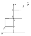
- Fig. 1 shows on the abscissa the values for the mains voltage U, where U N indicates a setpoint for the mains voltage. Along the ordinate are Values for the reactive power Q are plotted, wherein above the abscissa a voltage-increasing reactive power and below the abscissa a voltage-reducing reactive power is plotted.
- the control method according to the invention does not intervene until reaching the first upper limit value U 1 and does not change the current setpoint value for the reactive power. Only when the limit value U 1 is exceeded, the reactive power setpoint is lowered, ie, voltage-reducing reactive power is provided. The reactive power setpoint is subsequently lowered in time until either a limit value of the reactive power Q min is reached or until the limit value of the voltage U 1 is again undershot.
- the setpoint value for the reactive power is kept constant again, namely at the setpoint value achieved up to that point in time.
- the target value for the reactive power is increased again, and that from the time of falling below the limit U 2 , corresponding to the duration of falling below the limit U 2 .
- the reference value of the reactive power is further increased until a predetermined reactive power setpoint, for example zero, has been reached or until the limit value U 2 is again exceeded by a renewed increase in the mains voltage. Thereafter, the reactive power command value is kept constant again, namely on the setpoint reached up to this point.
- the control method according to the invention does not intervene until reaching the first lower limit value U 3 and does not change the current setpoint value for the reactive power. Only when the limit U 3 is exceeded, there is an increase in the reactive power setpoint, ie, voltage-boosting reactive power is provided.
- the reactive power setpoint is continuously increased until either a limit value of the reactive power Q max is reached or until the limit value of the voltage U 3 is again exceeded.
- the target value for the reactive power is lowered again, namely from the time of exceeding the limit value U 4 , corresponding to the duration of exceeding the limit value U 4 .
- the setpoint value of the reactive power is further reduced until a predetermined reactive power setpoint value, for example zero, has been reached or until the limit value U 4 is fallen below again by a renewed drop in the mains voltage. Thereafter, the reactive power command value is kept constant again, namely on the setpoint reached up to this point.
- Fig. 2 shows an alternative embodiment of the method in which the limits U 2 and U 4 are the same.
- the position of the nominal value rated voltage U N is not specified here, it can lie within the interval between U 3 and U 1 at any point and does not have to coincide with U 2 or U 4 .
- the setpoint value of the reactive power is increased until the preset value (for example, zero), and is then kept constant at this default value. Only when the threshold value U 3 is undershot in the event of a further drop in the mains voltage, the setpoint value of the reactive power is further increased.
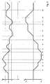
- FIG. 3 The illustrated concept can be applied Fig. 3 simply clarify.
- the upper part of the Fig. 3 shows an example voltage curve over time.
- U 1 the first lower limit of the voltage U 3
- U 2 U 4 was selected. This corresponds to the presentation Fig. 2 ,
- the lower part of the Fig. 3 shows the corresponding course of the target value of the reactive power Q over time, which results from the inventive method.
- the default value zero, the upper limit value Q max and the lower limit value Q min can be recognized .
- the voltage rises gradually and reaches at time t 1 the first upper limit value U. 1
- the setpoint value of the reactive power Q is lowered with time, as long as the voltage exceeds the limit U 1 .
- the linear decrease of the setpoint value for the reactive power Q results from the fact that a time-constant setpoint decrease is defined, as in the description Fig. 1 shown above. Basically, nonlinear forms are possible when decibels and / or increases. For example, also possible to form the setpoint value change proportional to the tension deviation, dQ / dt ⁇ (U N - U).
- the voltage falls below the upper limit U 1 , in this time interval, the target value of the reactive power Q is kept constant at the value that was reached up to the time t 2 .
- the voltage again exceeds the upper limit U 1 and there is again a time-constant reduction of the setpoint for the reactive power Q.
- the limit value of the reactive power Q min is reached, from this point on, the setpoint value of the reactive power Q not further lowered, but kept constant at the value Q min , although the voltage is still above the upper limit U 1 and temporarily even further increases.
- the voltage again falls below the upper limit U 1 , the desired value of the reactive power is kept constant at the previously reached value Q min .
- the voltage falls below the second lower limit U 2 , therefore, the target value of the reactive power Q is increased again over time.
- the lower limit value U 2 is exceeded again and the setpoint value of the reactive power Q is kept constant at the value reached up to that point. From the time t 8 , the lower limit value U 2 again falls below, therefore, the target value of the reactive power Q is further increased until the time t 9, the default value zero is reached. From this point on, the setpoint value of the reactive power Q is kept constant at the default value zero.
- the voltage falls below the first lower limit U 3 , therefore, the target value of the reactive power Q is increased over time. From t 11 to t 12 , the voltage returns to the range between the limit values U 3 and U 4 , so that in this time interval the target value of the reactive power Q is kept constant at the value reached at time t 11 .
- the voltage again falls below the lower limit U 3 , therefore, the target value of the reactive power Q is further increased until the time limit t 13 of the limit value Q max of the reactive power is reached.
- the setpoint value of the reactive power is kept constant until the upper limit of the voltage U 4 is exceeded again until the time t 14 .
- the target value of the reactive power Q is lowered again with time and reached at the time t 15 is the default value zero, on which it is held constant again from t 15 .
- Fig. 4 shows a case in which the intervals between U 2 and U 1 and between U 3 and U 4 partially overlap each other.
- Fig. 5 shows the case that the two intervals completely overlap each other.
- the setpoint value of the reactive power is kept constant and only when U 1 is exceeded or below U 3 is a change in the setpoint value of the reactive power commences.
- FIGS. 1 . 2 . 4 and 5 thus show various examples of how an adaptation of the method to different site and network conditions is possible by changing the limits for the voltage U 1 ... U 4 .
- the procedure is done in such a way implement that you can easily change the limits U 1 ... U 4 by changing operating parameters of the wind turbine or that the limits are shifted according to the setpoint of the mains voltage U N.
- Fig. 6 illustrates the method accordingly Fig. 1 in the event that the sign conventions are chosen differently, namely in such a way that reactive power above the abscissa has a voltage-lowering effect and reactive power below the abscissa has a voltage-increasing effect.
Abstract
Description
Die vorliegende Erfindung betrifft ein Verfahren zum Betreiben einer Windenergieanlage mit einer spannungsabhängigen Steuerung einer bereitzustellenden elektrischen Blindgröße, bei dem ein Sollwert für die elektrische Blindgröße berechnet wird.The present invention relates to a method for operating a wind energy plant with a voltage-dependent control of an electrical reactive quantity to be provided, in which a setpoint value for the electrical reactive variable is calculated.
Von heutigen Windparks und deren Windenergieanlagen wird verlangt, daß sie spannungsstützend mit dem elektrischen Netz verbunden sind. Es ist daher vorgesehen, dass von den einzelnen Windenergieanlagen und/oder von dem Windpark insgesamt eine spannungsabhängige Blindleistungsbereitstellung erfolgt. Diese wird auch als Automatic Voltage Regulation (AVR) bezeichnet und dient bei Spannungsschwankungen, die sich innerhalb gewisser Bereiche halten, dazu, durch Bereitstellung von Blindleistung und/oder Blindstrom die Spannung im Netz konstant zu halten.Today's wind farms and their wind turbines are required to be voltage-connected to the electrical grid. It is therefore envisaged that a total of the individual wind turbines and / or the wind farm is a voltage-dependent reactive power provision. This is also known as Automatic Voltage Regulation (AVR) and is designed to keep the voltage in the grid constant by providing reactive power and / or reactive current for voltage fluctuations that are within certain ranges.
Aus
Aus
Aus
Der Erfindung liegt die Aufgabe zugrunde, ein Verfahren zum Betreiben einer Windenergieanlage bereitzustellen, bei dem in kürzest möglicher Zeit auf Spannungsänderungen durch Bereitstellung einer elektrischen Blindgröße reagiert werden kann.The invention has for its object to provide a method for operating a wind turbine, can be reacted in the shortest possible time to voltage changes by providing an electrical dummy size.
Erfindungsgemäß wird die Aufgabe durch ein Verfahren mit den Merkmalen nach Anspruch 1 gelöst. Vorteilhafte Ausgestaltungen bilden den Gegenstand der Unteransprüche.According to the invention the object is achieved by a method having the features of claim 1. Advantageous embodiments form the subject of the dependent claims.
Die Erfindung betrifft ein Verfahren zum Betreiben einer Windenergieanlage mit einer spannungsabhängigen Steuerung einer bereitzustellenden elektrischen Blindgröße. Für die elektrische Blindgröße wird bei dem erfindungsgemäßen Verfahren ein Sollwert berechnet. Das erfindungsgemäße Verfahren geht dabei davon aus, dass für die Netzspannung ein erster oberer Grenzwert und/oder ein erster unterer Grenzwert der Netzspannung definiert ist. Erfindungsgemäß sind also drei Varianten von dem erfindungsgemäßen Verfahren umfasst, die den Fall betreffen, dass (erstens) nur ein erster oberer Grenzwert, (zweitens) nur ein erster unterer Grenzwert und (drittens) sowohl ein erster oberer Grenzwert als auch ein erster unterer Grenzwert definiert sind. Das erfindungsgemäße Verfahren sieht vor, dass, wenn der Istwert der Netzspannung den ersten oberen Grenzwert überschreitet, der Sollwert der elektrischen Blindgröße derart vergrößert oder verkleinert wird, dass der Abweichung des Istwerts der Netzspannung von ihrem Sollwert entgegengewirkt wird. Ebenfalls sieht das erfindungsgemäße Verfahren in den Varianten zwei und drei vor, dass bei einem Unterschreiten des ersten unteren Grenzwerts der Sollwert der elektrischen Blindgröße derart vergrößert oder verkleinert wird, dass der Abweichung des Istwerts der Netzspannung von ihrem Sollwert entgegengewirkt wird. Erfindungsgemäß wird der Sollwert der elektrischen Blindgröße zeitlich fortlaufend weiter vergrößert oder verkleinert, solange der Istwert der Netzspannung den ersten oberen Grenzwert überschreitet oder den ersten unteren Grenzwert unterschreitet. Bei dem erfindungsgemäßen Verfahren wird also mit dem Überschreiten des ersten oberen Grenzwerts und/oder mit dem Unterschreiten des ersten unteren Grenzwerts eine zeitlich fortlaufende Veränderung des Sollwerts der elektrischen Blindgröße in Gang gesetzt. Diese Veränderung hält an, solange dieThe invention relates to a method for operating a wind energy plant with a voltage-dependent control of an electrical reactive quantity to be provided. For the electrical dummy size is in the inventive Method calculated a setpoint. The method according to the invention is based on the assumption that a first upper limit value and / or a first lower limit value of the mains voltage is defined for the mains voltage. According to the invention, therefore, three variants of the method according to the invention are included which relate to the case that (first) only a first upper limit value, (secondly) only a first lower limit value and (third) both a first upper limit value and a first lower limit value are defined are. The inventive method provides that when the actual value of the mains voltage exceeds the first upper limit, the target value of the electrical dummy size is increased or decreased so that the deviation of the actual value of the mains voltage is counteracted by its target value. The method according to the invention also provides in variants two and three that when the first lower limit value is undershot, the nominal value of the electrical reactive variable is increased or decreased in such a way that the deviation of the actual value of the mains voltage from its desired value is counteracted. According to the target value of the electrical dummy size is continuously increased or decreased in time continuously, as long as the actual value of the mains voltage exceeds the first upper limit or falls below the first lower limit. In the method according to the invention, therefore, when the first upper limit value is exceeded and / or the first lower limit value is undershot, a chronologically continuous change in the setpoint value of the electrical reactive variable is initiated. This change continues as long as the
Istwerte der Netzspannung oberhalb oder unterhalb des ersten oberen Grenzwerts bzw. des ersten unteren Grenzwerts liegen.Actual values of the mains voltage are above or below the first upper limit or the first lower limit.
Im Zusammenhang mit der Bereitstellung von Blindleistung sind verschiedene fachsprachliche Ausdrucksweisen gebräuchlich:In connection with the provision of reactive power, various technical expressions are common:
Es kann beispielsweise von der Bereitstellung kapazitiver oder induktiver Blindleistung gesprochen werden, der Einspeisung oder Entnahme von Blindleistung oder von einem übererregten oder untererregten Betrieb. Nachfolgend wird, sofern nicht ausdrücklich anders erwähnt, stets von einer spannungssteigernden Blindleistung bzw. von einer spannungssenkenden Blindleistung gesprochen. Bei der Betrachtung von Windenergieanlagen am Netz haben sich auch unterschiedliche Vorzeichenkonventionen im Zusammenhang mit elektrischen Blindgrößen, sei es nun elektrische Blindleistung oder der elektrische Blindstrom etabliert. Nachfolgend wird ein positives Vorzeichen für spannungssteigernde Blindleistung und ein negatives Vorzeichen für spannungssenkende Blindleistung eingesetzt.For example, one can speak of providing capacitive or inductive reactive power, feeding or removing reactive power, or over-energized or under-energized operation. In the following, unless otherwise stated, there is always talk of a voltage-increasing reactive power or of a voltage-reducing reactive power. When considering wind turbines on the grid, different sign conventions have also been established in connection with electrical reactive variables, be it electrical reactive power or electric reactive current. Subsequently, a positive sign is used for voltage-increasing reactive power and a negative sign for voltage-reducing reactive power.
In einer bevorzugten Weiterführung des erfindungsgemäßen Verfahrens ist der erste obere Grenzwert der Netzspannung größer als der Sollwert oder gleich dem Sollwert für die Netzspannung. Ebenfalls ist der erste untere Grenzwert der Netzspannung kleiner oder gleich dem Sollwert der Netzspannung. Erster oberer und unterer Grenzwert liegen also bevorzugt oberhalb bzw. unterhalb des Sollwerts für die Netzspannung.In a preferred continuation of the method according to the invention, the first upper limit of the mains voltage is greater than the desired value or equal to the nominal value for the mains voltage. Also, the first lower limit of the mains voltage is less than or equal to the setpoint of the mains voltage. The first upper and lower limit values are therefore preferably above or below the setpoint for the mains voltage.
In einer bevorzugten Ausgestaltung wird der Sollwert der elektrischen Blindgröße vergrößert oder verkleinert, bis der Sollwert einen Maximalwert oder einen Minimalwert erreicht hat. Bei dieser bevorzugten Ausgestaltung wird die Änderung des Sollwerts für die elektrische Blindgröße beendet, wenn der Sollwert einen vorbestimmten Maximal- oder Minimalwert erreicht hat. Der Vorteil dieser Begrenzung besteht darin, dass, wenn die Windenergieanlage keine netzstützende Funktion entfalten kann, ab einem bestimmten vorgesehenen Maximal- oder Minimalwert eine weitere Erhöhung oder Absenkung der elektrischen Blindgröße unterbrochen wird.In a preferred embodiment, the setpoint of the electrical dummy size is increased or decreased until the setpoint has reached a maximum value or a minimum value. In this preferred embodiment, the change of the target value for the electric blank is terminated when the target value has reached a predetermined maximum or minimum value. The advantage of this limitation is that, if the wind turbine can not develop a network-supporting function, a further increase or decrease in the electrical reactive variable is interrupted beyond a certain maximum or minimum value provided.
In einer bevorzugten Ausgestaltung ist zusätzlich ein zweiter unterer Grenzwert definiert, der kleiner oder gleich dem ersten oberen Grenzwert ist. Wenn der Istwert der Spannung den zweiten unteren Grenzwert unterschreitet, wird der Sollwert der Blindgröße zeitlich fortlaufend vergrößert oder verkleinert, solange bis ein erster vorbestimmter Sollwert für die elektrische Blindgröße erreicht wurde. Analog hierzu ist bevorzugt auch ein zweiter oberer Grenzwert definiert, der größer oder gleich dem ersten unteren Grenzwert ist, wobei dann, wenn der Istwert der Netzspannung den zweiten oberen Grenzwert überschreitet, der Sollwert für die elektrische Blindgröße zeitlich fortlaufend vergrößert oder verkleinert wird, solange bis ein zweiter vorbestimmter Sollwert für die elektrische Blindgröße erreicht wurde. Die zusätzlichen zweiten oberen und unteren Grenzwerte erlauben es, einen Spannungsbereich zu definieren, in dem ein Anheben bzw. ein Absenken auf vorbestimmte Sollwerte für die elektrische Blindgröße möglich sind. In einer bevorzugten Ausgestaltung sind die vorbestimmten Sollwerte für die erste und die zweite elektrische Blindgröße gleich, besonders bevorzugt besitzen beide Sollwerte den Wert Null. In dieser Ausgestaltung findet also bei einem Unterschreiten des zweiten unteren Grenzwerts eine Rückführung des Sollwerts für die elektrische Blindgröße auf den Wert Null statt. Mit Einführung des zweiten oberen und unteren Grenzwerts kann eine zumindest stückweise stetige Regelung vorgenommen werden.In a preferred embodiment, a second lower limit is additionally defined, which is less than or equal to the first upper limit. If the actual value of the voltage falls below the second lower limit value, the setpoint value of the dummy quantity is continuously increased or decreased in time until a first predetermined setpoint value for the electrical dummy quantity has been reached. Analogously, a second upper limit value is preferably defined which is greater than or equal to the first lower limit value, wherein, if the actual value of the mains voltage exceeds the second upper limit value, the setpoint value for the electrical reactive variable is continuously increased or decreased in time, until a second predetermined one Setpoint for the electrical dummy size has been reached. The additional second upper and lower limits make it possible to define a voltage range in which it is possible to raise or lower to predetermined set values for the electrical dummy size. In a preferred embodiment, the predetermined setpoint values for the first and the second electrical dummy variables are the same, particularly preferably both setpoint values have the value zero. In this embodiment, therefore, when the second lower limit value is undershot, the setpoint value for the electrical dummy variable is reduced to zero. With the introduction of the second upper and lower limit value, an at least piecewise continuous regulation can be carried out.
In einer bevorzugten Ausgestaltung wird, wenn der Istwert der Netzspannung den ersten oberen Grenzwert wieder unterschreitet und/oder den ersten unteren Grenzwert wieder überschreitet, der Sollwert für die elektrische Blindgröße auf einen zeitlich konstanten Wert gesetzt. Der zeitlich konstante Wert für die elektrische Blindgröße ist dabei bevorzugt gleich dem aktuellen Sollwert der elektrischen Blindgröße im Zeitpunkt des Wiederüberschreitens des ersten unteren Grenzwerts bzw. des Wiederunterschreitens des ersten oberen Grenzwerts. In dieser Ausgestaltung wird also bei einem Wiedereintritt des Istwerts der Netzspannung in den vom ersten oberen Grenzwert und ersten unteren Grenzwert definierten Bereich der Sollwert für die elektrische Blindgröße auf seinem aktuellen Wert konstant gehalten. Analog zu der vorstehend beschriebenen Ausgestaltung des erfindungsgemäßen Verfahrens, bei der der zeitlich konstante Wert für die Blindgröße vorgesehen ist, kann auch vorgesehen sein, dass, wenn der Istwert der Netzspannung den zweiten unteren Grenzwert wieder überschreitet und/oder den zweiten oberen Grenzwert wieder unterschreitet, der Sollwert für die elektrische Blindgröße auf einen zeitlich konstanten Wert gesetzt wird. Hierbei kann der zeitlich konstante Wert bevorzugt wieder der aktuelle Sollwert der elektrischen Blindgröße sein.In a preferred embodiment, when the actual value of the mains voltage falls below the first upper limit value again and / or exceeds the first lower limit value again, the setpoint value for the electrical dummy variable is set to a time-constant value. The time constant value for the electrical dummy size is preferably equal to the current setpoint of the electrical dummy size at the time of exceeding the first lower limit value or the falling below the first upper limit value. In this embodiment, therefore, when the actual value of the mains voltage re-enters the range defined by the first upper limit value and the first lower limit value, the nominal value for the electrical reactive variable is kept constant at its current value. Analogous to the As described above embodiment of the method according to the invention, in which the time constant value is provided for the dummy size, can also be provided that when the actual value of the mains voltage exceeds the second lower limit again and / or falls below the second upper limit again, the target value for the electrical dummy size is set to a constant value over time. In this case, the time-constant value may preferably again be the current setpoint value of the electrical dummy variable.
In einer bevorzugten Ausgestaltung des erfindungsgemäßen Verfahrens ist der zweite obere Grenzwert der Netzspannung kleiner oder gleich dem ersten oberen Grenzwert der Netzspannung. Ebenso ist der zweite untere Grenzwert der Netzspannung bevorzugt größer oder gleich dem ersten unteren Grenzwert der Netzspannung.In a preferred embodiment of the method according to the invention, the second upper limit of the mains voltage is less than or equal to the first upper limit of the mains voltage. Likewise, the second lower limit of the mains voltage is preferably greater than or equal to the first lower limit of the mains voltage.
Dem Fachmann ist allgemein geläufig, dass es mehrere Möglichkeiten der Darstellung von elektrischen Blindgrößen gibt:It is generally known to the person skilled in the art that there are several possibilities for the representation of electrical reactive variables:
Blindleistung, Blindstrom, Phasenwinkel oder Leistungsfaktor.Reactive power, reactive current, phase angle or power factor.
Ebenfalls ist dem Fachmann allgemein bekannt, dass zur Bereitstellung und Beeinflussung einer elektrischen Blindgröße auf eine Steuerung des Generators und/oder des Umrichtersystems und/oder des Phasenschiebersystems abgestellt werden kann.It is also generally known to the person skilled in the art that for the provision and influencing of an electrical dummy variable, a control of the Generator and / or the inverter system and / or the phase shifter system can be turned off.
In einer bevorzugten Ausgestaltung des erfindungsgemäßen Verfahrens sind die Grenzwerte bezogen auf den Sollwert für die Netzspannung einstellbar.In a preferred embodiment of the method according to the invention, the limit values are adjustable relative to the setpoint value for the mains voltage.
Das erfindungsgemäße Verfahren wird nachfolgend an einem Beispiel näher erläutert. Es zeigt:
- Fig. 1
- eine Darstellung der Sollwertbestimmung für die Blindleistung abhängig von der gemessenen Spannung,
- Fig. 2
- eine Darstellung einer alternativen Sollwertbestimmung für die Blind- leistung abhängig von der gemessenen Spannung,
- Fig. 3
- einen beispielhaften Verlauf der Spannung und des Sollwertes der Blindleistung über der Zeit,
- Fig. 4 und 5
- Darstellungen weiterer alternativer Sollwertbestimmungen für die Blindleistung abhängig von der gemessenen Spannung, und
- Fig. 6
- eine Darstellung der Sollwertbestimmung nach
Fig. 1 mit anderer Vorzeichenwahl.
- Fig. 1
- a representation of the setpoint determination for the reactive power as a function of the measured voltage,
- Fig. 2
- a representation of an alternative nominal value determination for the reactive power as a function of the measured voltage,
- Fig. 3
- an exemplary profile of the voltage and the nominal value of the reactive power over time,
- 4 and 5
- Representations of further alternative setpoint determinations for the reactive power depending on the measured voltage, and
- Fig. 6
- a representation of the setpoint determination after
Fig. 1 with different sign choice.
Bei einem Ansteigen der Netzspannung greift das erfindungsgemäße Regelverfahren bis zum Erreichen des ersten oberen Grenzwertes U1 nicht ein und verändert nicht den aktuellen Sollwert für die Blindleistung. Erst wenn der Grenzwert U1 überschritten wird, erfolgt eine Absenkung des Blindleistungssollwertes, d.h. es wird spannungssenkende Blindleistung bereitgestellt. Der Blindleistungssollwert wird zeitlich nachfolgend solange immer weiter abgesenkt, bis entweder ein Grenzwert der Blindleistung Qmin erreicht ist oder bis der Grenzwert der Spannung U1 wieder unterschritten wird. Der Sollwert der Blindleistung wird also ab dem Zeitpunkt, zu dem der Grenzwert U1 überschritten wird, entsprechend der Dauer des Überschreitens des Grenzwertes U1 immer weiter abgesenkt, wobei das Absenken des Sollwertes beispielsweise mit einem konstanten Betrag pro Zeiteinheit erfolgen kann: dQ/dt = const. Wenn ein Grenzwert der Blindleistung Qmin erreicht wird, so wird ab diesem Zeitpunkt der Sollwert für die Blindleistung auf diesem Wert konstant gehalten, wie in
Wenn die Netzspannung den Grenzwert U1 wieder unterschreitet, so wird der Sollwert für die Blindleistung wieder konstant gehalten, und zwar auf dem bis zu diesem Zeitpunkt erreichten Sollwert.If the mains voltage again falls below the limit value U 1 , then the setpoint value for the reactive power is kept constant again, namely at the setpoint value achieved up to that point in time.
Erst wenn die Netzspannung auch den zweiten unteren Grenzwert U2 unterschreitet, wird der Sollwert für die Blindleistung wieder erhöht, und zwar ab dem Zeitpunkt des Unterschreitens des Grenzwertes U2, entsprechend der Dauer des Unterschreitens des Grenzwertes U2. Der Sollwert der Blindleistung wird solange weiter erhöht, bis ein vorgegebener Blindleistungssollwert, beispielsweise Null, erreicht wurde oder bis durch ein erneutes Ansteigen der Netzspannung der Grenzwert U2 wieder überschritten wird. Danach wird der Blindleistungssollwert wieder konstant gehalten, und zwar auf dem bis zu diesem Zeitpunkt erreichten Sollwert.Only when the mains voltage falls below the second lower limit U 2 , the target value for the reactive power is increased again, and that from the time of falling below the limit U 2 , corresponding to the duration of falling below the limit U 2 . The reference value of the reactive power is further increased until a predetermined reactive power setpoint, for example zero, has been reached or until the limit value U 2 is again exceeded by a renewed increase in the mains voltage. Thereafter, the reactive power command value is kept constant again, namely on the setpoint reached up to this point.
Bei einem Absinken der Netzspannung greift das erfindungsgemäße Regelverfahren bis zum Erreichen des ersten unteren Grenzwertes U3 nicht ein und verändert nicht den aktuellen Sollwert für die Blindleistung. Erst wenn der Grenzwert U3 unterschritten wird, erfolgt eine Erhöhung des Blindleistungssollwertes, d.h. es wird spannungssteigernde Blindleistung bereitgestellt. Der Blindleistungssollwert wird solange immer weiter erhöht, bis entweder ein Grenzwert der Blindleistung Qmax erreicht ist oder bis der Grenzwert der Spannung U3 wieder überschritten wird. Der Sollwert der Blindleistung wird also ab dem Zeitpunkt, zu dem der Grenzwert U3 unterschritten wird, entsprechend der Dauer des Unterschreitens des Grenzwertes U3 immer weiter erhöht, wobei das Erhöhen des Sollwertes beispielsweise mit einem konstanten Betrag pro Zeiteinheit erfolgen kann: dQ/dt = const. Wenn ein Grenzwert der Blindleistung Qmax erreicht wird, so wird ab diesem Zeitpunkt der Sollwert für die Blindleistung auf diesem Wert konstant gehalten, wie in
Wenn die Netzspannung den Grenzwert U3 wieder überschreitet, so wird der Sollwert für die Blindleistung wieder konstant gehalten, und zwar auf dem bis zu diesem Zeitpunkt erreichten Sollwert.If the mains voltage again exceeds the limit value U 3 , the reactive power setpoint is kept constant again, up to the setpoint value achieved up to that point.
Erst wenn die Netzspannung auch den zweiten oberen Grenzwert U4 überschreitet, wird der Sollwert für die Blindleistung wieder abgesenkt, und zwar ab dem Zeitpunkt des Überschreitens des Grenzwertes U4, entsprechend der Dauer des Überschreitens des Grenzwertes U4. Der Sollwert der Blindleistung wird solange weiter gesenkt, bis ein vorgegebener Blindleistungssollwert, beispielsweise Null, erreicht wurde oder bis durch ein erneutes Absinken der Netzspannung der Grenzwert U4 wieder unterschritten wird. Danach wird der Blindleistungssollwert wieder konstant gehalten, und zwar auf dem bis zu diesem Zeitpunkt erreichten Sollwert.Only when the mains voltage also exceeds the second upper limit U 4 , the target value for the reactive power is lowered again, namely from the time of exceeding the limit value U 4 , corresponding to the duration of exceeding the limit value U 4 . The setpoint value of the reactive power is further reduced until a predetermined reactive power setpoint value, for example zero, has been reached or until the limit value U 4 is fallen below again by a renewed drop in the mains voltage. Thereafter, the reactive power command value is kept constant again, namely on the setpoint reached up to this point.
Angenommen, es sei ein Sollwert der Blindleistung unterhalb der Abszisse (= spannungssenkende Blindleistung) eingestellt und die Netzspannung sinke aus dem Intervall zwischen U2 und U1 kommend unter den Grenzwert U2 ab, dann wird der Sollwert der Blindleistung erhöht, bis der Vorgabewert (beispielsweise Null) erreicht ist, und wird dann auf diesem Vorgabewert konstant gehalten. Erst wenn bei einem weiteren Absinken der Netzspannung der Grenzwert U3 unterschritten wird, wird der Sollwert der Blindleistung weiter erhöht.Assuming that a setpoint value of the reactive power is set below the abscissa (= voltage-reducing reactive power) and the line voltage drops below the limit value U 2 coming from the interval between U 2 and U 1 , the setpoint value of the reactive power is increased until the preset value ( for example, zero), and is then kept constant at this default value. Only when the threshold value U 3 is undershot in the event of a further drop in the mains voltage, the setpoint value of the reactive power is further increased.
Entsprechend wird im umgekehrten Fall, dass ein Sollwert der Blindleistung oberhalb der Abszisse eingestellt ist (= spannungssteigernde Blindleistung) und die Netzspannung aus dem Intervall zwischen U3 und U4 kommend weiter über U4 ansteigt, der Sollwert der Blindleistung zunächst abgesenkt, bis der Vorgabewert (beispielsweise Null) erreicht ist, und danach konstant gehalten. Erst wenn bei einem weiteren Ansteigen der Netzspannung der Grenzwert U1 überschritten wird, wird der Sollwert der Blindleistung weiter abgesenkt.Accordingly, in the opposite case, that a target value of the reactive power is set above the abscissa (= voltage-increasing reactive power) and the mains voltage from the interval between U 3 and U 4 coming further above U 4 increases, the target value of the reactive power initially lowered until the default value (eg, zero), and then held constant. Only when the limit U 1 is exceeded in a further increase in the mains voltage, the target value of the reactive power is further lowered.
Das dargestellte Konzept lässt sich an
Der untere Teil der
Im Zeitintervall zwischen dem Koordinatenursprung und dem Zeitpunkt t1 steigt die Spannung allmählich an und erreicht zum Zeitpunkt t1 den ersten oberen Grenzwert U1. Wie im unteren Teil des Diagramms in
Im Zeitintervall von t2 bis t3 unterschreitet die Spannung den oberen Grenzwert U1, in diesem Zeitintervall wird der Sollwert der Blindleistung Q auf dem Wert konstant gehalten, der bis zu dem Zeitpunkt t2 erreicht wurde. Ab dem Zeitpunkt t3 überschreitet die Spannung wieder den oberen Grenzwert U1 und es erfolgt wieder eine zeitlich konstante Absenkung des Sollwertes für die Blindleistung Q. Im Zeitpunkt t4 ist der Grenzwert der Blindleistung Qmin erreicht, ab diesem Zeitpunkt wird der Sollwert der Blindleistung Q nicht weiter abgesenkt, sondern auf dem Wert Qmin konstant gehalten, obwohl die Spannung weiterhin über dem oberen Grenzwert U1 liegt und zeitweise sogar noch weiter ansteigt. Zum Zeitpunkt t5 unterschreitet die Spannung wieder den oberen Grenzwert U1, der Sollwert der Blindleistung wird weiterhin auf dem bis dahin erreichten Wert Qmin konstant gehalten. Zum Zeitpunkt t6 unterschreitet die Spannung den zweiten unteren Grenzwert U2, deshalb wird der Sollwert der Blindleistung Q wieder mit der Zeit erhöht. Zum Zeitpunkt t7 wird der untere Grenzwert U2 wieder überschritten und der Sollwert der Blindleistung Q auf dem bis dahin erreichten Wert konstant gehalten. Ab dem Zeitpunkt t8 wird der untere Grenzwert U2 wieder unterschritten, deshalb wird der Sollwert der Blindleistung Q weiter erhöht, bis zum Zeitpunkt t9 der Vorgabewert Null erreicht ist. Ab diesem Zeitpunkt wird der Sollwert der Blindleistung Q auf dem Vorgabewert Null konstant gehalten.In the time interval from t 2 to t 3 , the voltage falls below the upper limit U 1 , in this time interval, the target value of the reactive power Q is kept constant at the value that was reached up to the time t 2 . From At the time t 3 , the voltage again exceeds the upper limit U 1 and there is again a time-constant reduction of the setpoint for the reactive power Q. At the time t 4 , the limit value of the reactive power Q min is reached, from this point on, the setpoint value of the reactive power Q not further lowered, but kept constant at the value Q min , although the voltage is still above the upper limit U 1 and temporarily even further increases. At time t 5 , the voltage again falls below the upper limit U 1 , the desired value of the reactive power is kept constant at the previously reached value Q min . At time t 6 , the voltage falls below the second lower limit U 2 , therefore, the target value of the reactive power Q is increased again over time. At time t 7 , the lower limit value U 2 is exceeded again and the setpoint value of the reactive power Q is kept constant at the value reached up to that point. From the time t 8 , the lower limit value U 2 again falls below, therefore, the target value of the reactive power Q is further increased until the time t 9, the default value zero is reached. From this point on, the setpoint value of the reactive power Q is kept constant at the default value zero.
Ab dem Zeitpunkt t10 unterschreitet die Spannung den ersten unteren Grenzwert U3, deshalb wird der Sollwert der Blindleistung Q mit der Zeit erhöht. Von t11 bis t12 kehrt die Spannung in den Bereich zwischen den Grenzwerten U3 und U4 zurück, so dass in diesem Zeitintervall der Sollwert der Blindleistung Q auf dem zum Zeitpunkt t11 erreichten Wert konstant gehalten wird.From the time t 10 , the voltage falls below the first lower limit U 3 , therefore, the target value of the reactive power Q is increased over time. From t 11 to t 12 , the voltage returns to the range between the limit values U 3 and U 4 , so that in this time interval the target value of the reactive power Q is kept constant at the value reached at time t 11 .
Ab t12 unterschreitet die Spannung wieder den unteren Grenzwert U3, deshalb wird der Sollwert der Blindleistung Q weiter erhöht, bis zum Zeitpunkt t13 der Grenzwert Qmax der Blindleistung erreicht ist. Ab t13 wird der Sollwert der Blindleistung solange konstant gehalten, bis zum Zeitpunkt t14 der obere Grenzwert der Spannung U4 wieder überschritten wird. Ab t14 wird deshalb der Sollwert der Blindleistung Q wieder mit der Zeit abgesenkt und erreicht zum Zeitpunkt t15 den Vorgabewert Null, auf dem er ab t15 wieder konstant gehalten wird.From t 12 , the voltage again falls below the lower limit U 3 , therefore, the target value of the reactive power Q is further increased until the time limit t 13 of the limit value Q max of the reactive power is reached. From t 13 , the setpoint value of the reactive power is kept constant until the upper limit of the voltage U 4 is exceeded again until the time t 14 . From t 14 , therefore, the target value of the reactive power Q is lowered again with time and reached at the time t 15 is the default value zero, on which it is held constant again from t 15 .
Weitere Variationen des Verfahrens sind in
Die
In gleicher Weise ist durch Veränderung der Grenzwerte für die Blindleistung, Qmin und Qmax, eine einfache Anpassung des Verfahrens möglich. Zur besseren Ausschöpfung der technischen Leistungsfähigkeit der Windenergieanlage ist es weiterhin sinnvoll, dass die Grenzwerte Qmin und Qmax entsprechend der momentanen Wirkleistungsabgabe und/oder Leistungsreserve der Windenergieanlage im laufenden Betrieb angepasst werden. Ein geeignetes Verfahren ist beispielsweise in
Claims (20)
dadurch gekennzeichnet, dass
characterized in that
Priority Applications (1)
| Application Number | Priority Date | Filing Date | Title |
|---|---|---|---|
| PL08020123T PL2066017T3 (en) | 2007-12-01 | 2008-11-19 | Method of operating a wind energy system with a voltage-dependent control for an electric reactive quantity to be provided |
Applications Claiming Priority (1)
| Application Number | Priority Date | Filing Date | Title |
|---|---|---|---|
| DE102007057925A DE102007057925A1 (en) | 2007-12-01 | 2007-12-01 | A method for operating a wind turbine with a voltage-dependent control of an electrical dummy size to be provided |
Publications (2)
| Publication Number | Publication Date |
|---|---|
| EP2066017A1 true EP2066017A1 (en) | 2009-06-03 |
| EP2066017B1 EP2066017B1 (en) | 2012-02-01 |
Family
ID=40456849
Family Applications (1)
| Application Number | Title | Priority Date | Filing Date |
|---|---|---|---|
| EP08020123A Active EP2066017B1 (en) | 2007-12-01 | 2008-11-19 | Method of operating a wind energy system with a voltage-dependent control for an electric reactive quantity to be provided |
Country Status (6)
| Country | Link |
|---|---|
| US (1) | US7638984B2 (en) |
| EP (1) | EP2066017B1 (en) |
| AT (1) | ATE544229T1 (en) |
| DE (1) | DE102007057925A1 (en) |
| ES (1) | ES2381311T3 (en) |
| PL (1) | PL2066017T3 (en) |
Cited By (2)
| Publication number | Priority date | Publication date | Assignee | Title |
|---|---|---|---|---|
| EP2346133A1 (en) * | 2010-01-14 | 2011-07-20 | Siemens Aktiengesellschaft | Converter device and method for converting electrical power |
| US8970057B2 (en) | 2010-03-31 | 2015-03-03 | Vestas Wind Systems A/S | Method of operating a wind turbine, wind turbine, wind turbine controlling system, and processing system |
Families Citing this family (3)
| Publication number | Priority date | Publication date | Assignee | Title |
|---|---|---|---|---|
| DE102008028568A1 (en) * | 2008-06-16 | 2009-12-31 | Nordex Energy Gmbh | Method for controlling a wind energy plant |
| DE102013208410A1 (en) | 2013-05-07 | 2014-11-13 | Wobben Properties Gmbh | Method for feeding electrical power into an electrical supply network |
| DE102014209332A1 (en) | 2014-05-16 | 2015-11-19 | Senvion Gmbh | Wind turbine with improved overvoltage protection |
Citations (7)
| Publication number | Priority date | Publication date | Assignee | Title |
|---|---|---|---|---|
| JP2000014011A (en) * | 1998-06-22 | 2000-01-14 | Hitachi Ltd | Voltage reactive power control device |
| FR2823381A1 (en) * | 2001-04-05 | 2002-10-11 | Electricite De France | Voltage regulator for decentralized electric energy generator connected to distribution network, in which voltage measured a point of supply is used for active and reactive power regulation |
| EP1282774A1 (en) | 2000-05-11 | 2003-02-12 | Aloys Wobben | Method for operating a wind power station and wind power station |
| EP1386078A1 (en) | 2001-04-24 | 2004-02-04 | Aloys Wobben | Method for operating a wind energy plant |
| EP1508951A1 (en) | 2003-08-18 | 2005-02-23 | General Electric Company | Continuous reactive power support for wind turbine generators |
| FR2894087A1 (en) * | 2005-11-25 | 2007-06-01 | Schneider Electric Ind Sas | Control method for e.g. windborne type device, involves controlling voltage at device`s connection point to absorb/produce reactive power when voltage is within target range and reduce/increase active power when reactive power reaches limit |
| EP1841037A2 (en) * | 2006-03-29 | 2007-10-03 | General Electric Company | System, method, and article of manufacture for determining parameter values associated with an electrical grid |
Family Cites Families (3)
| Publication number | Priority date | Publication date | Assignee | Title |
|---|---|---|---|---|
| US7423412B2 (en) * | 2006-01-31 | 2008-09-09 | General Electric Company | Method, apparatus and computer program product for injecting current |
| US7453241B2 (en) * | 2006-11-29 | 2008-11-18 | Sunpower, Inc. | Electronic controller matching engine power to alternator power and maintaining engine frequency for a free-piston stirling engine driving a linear alternator |
| US7453412B2 (en) * | 2007-03-26 | 2008-11-18 | Motorola, Inc. | Nanostructured, magnetic tunable antennas for communication devices |
-
2007
- 2007-12-01 DE DE102007057925A patent/DE102007057925A1/en not_active Ceased
-
2008
- 2008-04-14 US US12/102,580 patent/US7638984B2/en active Active
- 2008-11-19 ES ES08020123T patent/ES2381311T3/en active Active
- 2008-11-19 EP EP08020123A patent/EP2066017B1/en active Active
- 2008-11-19 PL PL08020123T patent/PL2066017T3/en unknown
- 2008-11-19 AT AT08020123T patent/ATE544229T1/en active
Patent Citations (7)
| Publication number | Priority date | Publication date | Assignee | Title |
|---|---|---|---|---|
| JP2000014011A (en) * | 1998-06-22 | 2000-01-14 | Hitachi Ltd | Voltage reactive power control device |
| EP1282774A1 (en) | 2000-05-11 | 2003-02-12 | Aloys Wobben | Method for operating a wind power station and wind power station |
| FR2823381A1 (en) * | 2001-04-05 | 2002-10-11 | Electricite De France | Voltage regulator for decentralized electric energy generator connected to distribution network, in which voltage measured a point of supply is used for active and reactive power regulation |
| EP1386078A1 (en) | 2001-04-24 | 2004-02-04 | Aloys Wobben | Method for operating a wind energy plant |
| EP1508951A1 (en) | 2003-08-18 | 2005-02-23 | General Electric Company | Continuous reactive power support for wind turbine generators |
| FR2894087A1 (en) * | 2005-11-25 | 2007-06-01 | Schneider Electric Ind Sas | Control method for e.g. windborne type device, involves controlling voltage at device`s connection point to absorb/produce reactive power when voltage is within target range and reduce/increase active power when reactive power reaches limit |
| EP1841037A2 (en) * | 2006-03-29 | 2007-10-03 | General Electric Company | System, method, and article of manufacture for determining parameter values associated with an electrical grid |
Cited By (4)
| Publication number | Priority date | Publication date | Assignee | Title |
|---|---|---|---|---|
| EP2346133A1 (en) * | 2010-01-14 | 2011-07-20 | Siemens Aktiengesellschaft | Converter device and method for converting electrical power |
| CN102130603A (en) * | 2010-01-14 | 2011-07-20 | 西门子公司 | Converter device and method for converting electrical power |
| EP2346133B1 (en) | 2010-01-14 | 2017-11-01 | Siemens Aktiengesellschaft | Converter device and method for converting electrical power |
| US8970057B2 (en) | 2010-03-31 | 2015-03-03 | Vestas Wind Systems A/S | Method of operating a wind turbine, wind turbine, wind turbine controlling system, and processing system |
Also Published As
| Publication number | Publication date |
|---|---|
| ATE544229T1 (en) | 2012-02-15 |
| EP2066017B1 (en) | 2012-02-01 |
| US20090140704A1 (en) | 2009-06-04 |
| ES2381311T3 (en) | 2012-05-25 |
| PL2066017T3 (en) | 2012-07-31 |
| US7638984B2 (en) | 2009-12-29 |
| DE102007057925A1 (en) | 2009-06-04 |
Similar Documents
| Publication | Publication Date | Title |
|---|---|---|
| EP1433238B2 (en) | Method for operating a wind park | |
| EP2872777B1 (en) | Method for controlling an electric generator | |
| EP2245717B1 (en) | Wind energy plant having a double-energized asynchronous generator and converter control | |
| EP1820963B1 (en) | Method of operating a wind power station | |
| EP2841766B1 (en) | Wind farm with fast local reactive power control | |
| EP2093419B1 (en) | Method of controlling a wind turbine and wind turbine | |
| EP2525083B1 (en) | Method for operating a wind turbine | |
| WO2011124696A2 (en) | Dynamic inertia regulation | |
| EP2989708A2 (en) | Method for feeding electrical power into an electrical supply network | |
| EP2066017B1 (en) | Method of operating a wind energy system with a voltage-dependent control for an electric reactive quantity to be provided | |
| EP3095168B1 (en) | Method and control device for operating a wind power plant and/or park and wind power plant and wind park | |
| DE102006039693A1 (en) | Method for operating wind turbines | |
| EP2273646B1 (en) | Method for reactive power compensation and apparatus for power generation in an electricity grid | |
| EP2288016A1 (en) | Wind energy assembly with adjustable speed characteristics curve | |
| EP1497556A1 (en) | Management system for the operation of a wind turbine | |
| EP2562414B1 (en) | Method for operating a wind power assembly when a power failure occurs with a decrease in power and such a wind power assembly | |
| DE102006051352B4 (en) | Method for operating a wind energy plant | |
| EP2213874B1 (en) | Method for operating a wind farm | |
| WO2019192993A1 (en) | Method for feeding electrical power into an electrical supply network | |
| WO2020148313A1 (en) | Wind turbine for feeding electrical power into an electrical supply network | |
| EP3806261B1 (en) | Method for feeding electrical power into an electrical supply network by means of a wind energy plant in a manner which controls voltage | |
| EP3425197B1 (en) | Power reduction in multiple wind energy assemblies in a wind farm | |
| WO2011085961A2 (en) | Method and device for synchronizing a generator in a network | |
| DE3224301C2 (en) | ||
| EP3511564A1 (en) | Method and system for controlling a wind energy plant |
Legal Events
| Date | Code | Title | Description |
|---|---|---|---|
| PUAI | Public reference made under article 153(3) epc to a published international application that has entered the european phase |
Free format text: ORIGINAL CODE: 0009012 |
|
| AK | Designated contracting states |
Kind code of ref document: A1 Designated state(s): AT BE BG CH CY CZ DE DK EE ES FI FR GB GR HR HU IE IS IT LI LT LU LV MC MT NL NO PL PT RO SE SI SK TR |
|
| AX | Request for extension of the european patent |
Extension state: AL BA MK RS |
|
| 17P | Request for examination filed |
Effective date: 20091203 |
|
| AKX | Designation fees paid |
Designated state(s): AT BE BG CH CY CZ DE DK EE ES FI FR GB GR HR HU IE IS IT LI LT LU LV MC MT NL NO PL PT RO SE SI SK TR |
|
| 17Q | First examination report despatched |
Effective date: 20100121 |
|
| GRAP | Despatch of communication of intention to grant a patent |
Free format text: ORIGINAL CODE: EPIDOSNIGR1 |
|
| GRAC | Information related to communication of intention to grant a patent modified |
Free format text: ORIGINAL CODE: EPIDOSCIGR1 |
|
| GRAS | Grant fee paid |
Free format text: ORIGINAL CODE: EPIDOSNIGR3 |
|
| GRAA | (expected) grant |
Free format text: ORIGINAL CODE: 0009210 |
|
| AK | Designated contracting states |
Kind code of ref document: B1 Designated state(s): AT BE BG CH CY CZ DE DK EE ES FI FR GB GR HR HU IE IS IT LI LT LU LV MC MT NL NO PL PT RO SE SI SK TR |
|
| REG | Reference to a national code |
Ref country code: GB Ref legal event code: FG4D Free format text: NOT ENGLISH |
|
| REG | Reference to a national code |
Ref country code: AT Ref legal event code: REF Ref document number: 544229 Country of ref document: AT Kind code of ref document: T Effective date: 20120215 Ref country code: CH Ref legal event code: EP |
|
| REG | Reference to a national code |
Ref country code: DE Ref legal event code: R096 Ref document number: 502008006263 Country of ref document: DE Effective date: 20120329 |
|
| REG | Reference to a national code |
Ref country code: ES Ref legal event code: FG2A Ref document number: 2381311 Country of ref document: ES Kind code of ref document: T3 Effective date: 20120525 |
|
| REG | Reference to a national code |
Ref country code: NL Ref legal event code: VDEP Effective date: 20120201 |
|
| LTIE | Lt: invalidation of european patent or patent extension |
Effective date: 20120201 |
|
| PG25 | Lapsed in a contracting state [announced via postgrant information from national office to epo] |
Ref country code: NO Free format text: LAPSE BECAUSE OF FAILURE TO SUBMIT A TRANSLATION OF THE DESCRIPTION OR TO PAY THE FEE WITHIN THE PRESCRIBED TIME-LIMIT Effective date: 20120501 Ref country code: IS Free format text: LAPSE BECAUSE OF FAILURE TO SUBMIT A TRANSLATION OF THE DESCRIPTION OR TO PAY THE FEE WITHIN THE PRESCRIBED TIME-LIMIT Effective date: 20120601 Ref country code: HR Free format text: LAPSE BECAUSE OF FAILURE TO SUBMIT A TRANSLATION OF THE DESCRIPTION OR TO PAY THE FEE WITHIN THE PRESCRIBED TIME-LIMIT Effective date: 20120201 Ref country code: LT Free format text: LAPSE BECAUSE OF FAILURE TO SUBMIT A TRANSLATION OF THE DESCRIPTION OR TO PAY THE FEE WITHIN THE PRESCRIBED TIME-LIMIT Effective date: 20120201 Ref country code: NL Free format text: LAPSE BECAUSE OF FAILURE TO SUBMIT A TRANSLATION OF THE DESCRIPTION OR TO PAY THE FEE WITHIN THE PRESCRIBED TIME-LIMIT Effective date: 20120201 |
|
| REG | Reference to a national code |
Ref country code: PL Ref legal event code: T3 |
|
| REG | Reference to a national code |
Ref country code: IE Ref legal event code: FD4D |
|
| PG25 | Lapsed in a contracting state [announced via postgrant information from national office to epo] |
Ref country code: PT Free format text: LAPSE BECAUSE OF FAILURE TO SUBMIT A TRANSLATION OF THE DESCRIPTION OR TO PAY THE FEE WITHIN THE PRESCRIBED TIME-LIMIT Effective date: 20120601 Ref country code: FI Free format text: LAPSE BECAUSE OF FAILURE TO SUBMIT A TRANSLATION OF THE DESCRIPTION OR TO PAY THE FEE WITHIN THE PRESCRIBED TIME-LIMIT Effective date: 20120201 Ref country code: LV Free format text: LAPSE BECAUSE OF FAILURE TO SUBMIT A TRANSLATION OF THE DESCRIPTION OR TO PAY THE FEE WITHIN THE PRESCRIBED TIME-LIMIT Effective date: 20120201 Ref country code: GR Free format text: LAPSE BECAUSE OF FAILURE TO SUBMIT A TRANSLATION OF THE DESCRIPTION OR TO PAY THE FEE WITHIN THE PRESCRIBED TIME-LIMIT Effective date: 20120502 |
|
| PG25 | Lapsed in a contracting state [announced via postgrant information from national office to epo] |
Ref country code: CY Free format text: LAPSE BECAUSE OF FAILURE TO SUBMIT A TRANSLATION OF THE DESCRIPTION OR TO PAY THE FEE WITHIN THE PRESCRIBED TIME-LIMIT Effective date: 20120201 |
|
| PG25 | Lapsed in a contracting state [announced via postgrant information from national office to epo] |
Ref country code: DK Free format text: LAPSE BECAUSE OF FAILURE TO SUBMIT A TRANSLATION OF THE DESCRIPTION OR TO PAY THE FEE WITHIN THE PRESCRIBED TIME-LIMIT Effective date: 20120201 Ref country code: SI Free format text: LAPSE BECAUSE OF FAILURE TO SUBMIT A TRANSLATION OF THE DESCRIPTION OR TO PAY THE FEE WITHIN THE PRESCRIBED TIME-LIMIT Effective date: 20120201 Ref country code: CZ Free format text: LAPSE BECAUSE OF FAILURE TO SUBMIT A TRANSLATION OF THE DESCRIPTION OR TO PAY THE FEE WITHIN THE PRESCRIBED TIME-LIMIT Effective date: 20120201 Ref country code: IE Free format text: LAPSE BECAUSE OF FAILURE TO SUBMIT A TRANSLATION OF THE DESCRIPTION OR TO PAY THE FEE WITHIN THE PRESCRIBED TIME-LIMIT Effective date: 20120201 Ref country code: RO Free format text: LAPSE BECAUSE OF FAILURE TO SUBMIT A TRANSLATION OF THE DESCRIPTION OR TO PAY THE FEE WITHIN THE PRESCRIBED TIME-LIMIT Effective date: 20120201 Ref country code: EE Free format text: LAPSE BECAUSE OF FAILURE TO SUBMIT A TRANSLATION OF THE DESCRIPTION OR TO PAY THE FEE WITHIN THE PRESCRIBED TIME-LIMIT Effective date: 20120201 Ref country code: SE Free format text: LAPSE BECAUSE OF FAILURE TO SUBMIT A TRANSLATION OF THE DESCRIPTION OR TO PAY THE FEE WITHIN THE PRESCRIBED TIME-LIMIT Effective date: 20120201 |
|
| PG25 | Lapsed in a contracting state [announced via postgrant information from national office to epo] |
Ref country code: SK Free format text: LAPSE BECAUSE OF FAILURE TO SUBMIT A TRANSLATION OF THE DESCRIPTION OR TO PAY THE FEE WITHIN THE PRESCRIBED TIME-LIMIT Effective date: 20120201 Ref country code: IT Free format text: LAPSE BECAUSE OF FAILURE TO SUBMIT A TRANSLATION OF THE DESCRIPTION OR TO PAY THE FEE WITHIN THE PRESCRIBED TIME-LIMIT Effective date: 20120201 |
|
| PLBE | No opposition filed within time limit |
Free format text: ORIGINAL CODE: 0009261 |
|
| STAA | Information on the status of an ep patent application or granted ep patent |
Free format text: STATUS: NO OPPOSITION FILED WITHIN TIME LIMIT |
|
| 26N | No opposition filed |
Effective date: 20121105 |
|
| REG | Reference to a national code |
Ref country code: DE Ref legal event code: R097 Ref document number: 502008006263 Country of ref document: DE Effective date: 20121105 |
|
| BERE | Be: lapsed |
Owner name: NORDEX ENERGY G.M.B.H. Effective date: 20121130 |
|
| REG | Reference to a national code |
Ref country code: CH Ref legal event code: PL |
|
| PG25 | Lapsed in a contracting state [announced via postgrant information from national office to epo] |
Ref country code: LI Free format text: LAPSE BECAUSE OF NON-PAYMENT OF DUE FEES Effective date: 20121130 Ref country code: CH Free format text: LAPSE BECAUSE OF NON-PAYMENT OF DUE FEES Effective date: 20121130 Ref country code: BG Free format text: LAPSE BECAUSE OF FAILURE TO SUBMIT A TRANSLATION OF THE DESCRIPTION OR TO PAY THE FEE WITHIN THE PRESCRIBED TIME-LIMIT Effective date: 20120501 |
|
| PG25 | Lapsed in a contracting state [announced via postgrant information from national office to epo] |
Ref country code: BE Free format text: LAPSE BECAUSE OF NON-PAYMENT OF DUE FEES Effective date: 20121130 |
|
| PG25 | Lapsed in a contracting state [announced via postgrant information from national office to epo] |
Ref country code: MT Free format text: LAPSE BECAUSE OF FAILURE TO SUBMIT A TRANSLATION OF THE DESCRIPTION OR TO PAY THE FEE WITHIN THE PRESCRIBED TIME-LIMIT Effective date: 20120201 |
|
| PG25 | Lapsed in a contracting state [announced via postgrant information from national office to epo] |
Ref country code: MC Free format text: LAPSE BECAUSE OF NON-PAYMENT OF DUE FEES Effective date: 20121130 |
|
| PG25 | Lapsed in a contracting state [announced via postgrant information from national office to epo] |
Ref country code: LU Free format text: LAPSE BECAUSE OF NON-PAYMENT OF DUE FEES Effective date: 20121119 |
|
| PG25 | Lapsed in a contracting state [announced via postgrant information from national office to epo] |
Ref country code: HU Free format text: LAPSE BECAUSE OF FAILURE TO SUBMIT A TRANSLATION OF THE DESCRIPTION OR TO PAY THE FEE WITHIN THE PRESCRIBED TIME-LIMIT Effective date: 20081119 |
|
| REG | Reference to a national code |
Ref country code: AT Ref legal event code: MM01 Ref document number: 544229 Country of ref document: AT Kind code of ref document: T Effective date: 20131119 |
|
| PG25 | Lapsed in a contracting state [announced via postgrant information from national office to epo] |
Ref country code: AT Free format text: LAPSE BECAUSE OF NON-PAYMENT OF DUE FEES Effective date: 20131119 |
|
| REG | Reference to a national code |
Ref country code: FR Ref legal event code: PLFP Year of fee payment: 8 |
|
| REG | Reference to a national code |
Ref country code: FR Ref legal event code: PLFP Year of fee payment: 9 |
|
| PGFP | Annual fee paid to national office [announced via postgrant information from national office to epo] |
Ref country code: ES Payment date: 20161124 Year of fee payment: 9 Ref country code: PL Payment date: 20161014 Year of fee payment: 9 |
|
| REG | Reference to a national code |
Ref country code: FR Ref legal event code: PLFP Year of fee payment: 10 |
|
| PG25 | Lapsed in a contracting state [announced via postgrant information from national office to epo] |
Ref country code: ES Free format text: LAPSE BECAUSE OF NON-PAYMENT OF DUE FEES Effective date: 20171120 |
|
| PGFP | Annual fee paid to national office [announced via postgrant information from national office to epo] |
Ref country code: HU Payment date: 20181215 Year of fee payment: 7 |
|
| PG25 | Lapsed in a contracting state [announced via postgrant information from national office to epo] |
Ref country code: PL Free format text: LAPSE BECAUSE OF NON-PAYMENT OF DUE FEES Effective date: 20171119 |
|
| REG | Reference to a national code |
Ref country code: DE Ref legal event code: R082 Ref document number: 502008006263 Country of ref document: DE Representative=s name: HAUCK PATENTANWALTSPARTNERSCHAFT MBB, DE Ref country code: DE Ref legal event code: R081 Ref document number: 502008006263 Country of ref document: DE Owner name: NORDEX ENERGY SE & CO. KG, DE Free format text: FORMER OWNER: NORDEX ENERGY GMBH, 22848 NORDERSTEDT, DE |
|
| PG25 | Lapsed in a contracting state [announced via postgrant information from national office to epo] |
Ref country code: TR Free format text: LAPSE BECAUSE OF NON-PAYMENT OF DUE FEES Effective date: 20191119 |
|
| P01 | Opt-out of the competence of the unified patent court (upc) registered |
Effective date: 20230602 |
|
| PGFP | Annual fee paid to national office [announced via postgrant information from national office to epo] |
Ref country code: GB Payment date: 20231123 Year of fee payment: 16 |
|
| PGFP | Annual fee paid to national office [announced via postgrant information from national office to epo] |
Ref country code: FR Payment date: 20231124 Year of fee payment: 16 Ref country code: DE Payment date: 20231120 Year of fee payment: 16 |