EP2066005B1 - Stator et modules de dents statoriques pour machines électriques - Google Patents
Stator et modules de dents statoriques pour machines électriques Download PDFInfo
- Publication number
- EP2066005B1 EP2066005B1 EP08169009.1A EP08169009A EP2066005B1 EP 2066005 B1 EP2066005 B1 EP 2066005B1 EP 08169009 A EP08169009 A EP 08169009A EP 2066005 B1 EP2066005 B1 EP 2066005B1
- Authority
- EP
- European Patent Office
- Prior art keywords
- stator
- rotor
- electrical machine
- stator tooth
- tooth modules
- Prior art date
- Legal status (The legal status is an assumption and is not a legal conclusion. Google has not performed a legal analysis and makes no representation as to the accuracy of the status listed.)
- Active
Links
- 238000003475 lamination Methods 0.000 claims description 14
- 238000001816 cooling Methods 0.000 claims description 10
- 230000004907 flux Effects 0.000 claims description 9
- 230000005291 magnetic effect Effects 0.000 claims description 8
- 239000007788 liquid Substances 0.000 claims 1
- 239000012260 resinous material Substances 0.000 claims 1
- 239000003302 ferromagnetic material Substances 0.000 description 13
- 125000006850 spacer group Chemical group 0.000 description 6
- XLYOFNOQVPJJNP-UHFFFAOYSA-N water Substances O XLYOFNOQVPJJNP-UHFFFAOYSA-N 0.000 description 6
- RYGMFSIKBFXOCR-UHFFFAOYSA-N Copper Chemical group [Cu] RYGMFSIKBFXOCR-UHFFFAOYSA-N 0.000 description 5
- 230000004323 axial length Effects 0.000 description 5
- 229910000975 Carbon steel Inorganic materials 0.000 description 4
- 229910052802 copper Inorganic materials 0.000 description 4
- 239000010949 copper Substances 0.000 description 4
- 239000010935 stainless steel Substances 0.000 description 4
- 229910001220 stainless steel Inorganic materials 0.000 description 4
- 229910000851 Alloy steel Inorganic materials 0.000 description 3
- 229910001141 Ductile iron Inorganic materials 0.000 description 3
- 230000008901 benefit Effects 0.000 description 3
- 239000010962 carbon steel Substances 0.000 description 3
- 230000033001 locomotion Effects 0.000 description 3
- 239000000463 material Substances 0.000 description 3
- 229910000831 Steel Inorganic materials 0.000 description 2
- 230000002528 anti-freeze Effects 0.000 description 2
- 238000013459 approach Methods 0.000 description 2
- 230000009286 beneficial effect Effects 0.000 description 2
- 230000006835 compression Effects 0.000 description 2
- 238000007906 compression Methods 0.000 description 2
- 230000005611 electricity Effects 0.000 description 2
- 238000005470 impregnation Methods 0.000 description 2
- 238000009413 insulation Methods 0.000 description 2
- XEEYBQQBJWHFJM-UHFFFAOYSA-N iron Substances [Fe] XEEYBQQBJWHFJM-UHFFFAOYSA-N 0.000 description 2
- 229910052742 iron Inorganic materials 0.000 description 2
- 238000000034 method Methods 0.000 description 2
- 239000011347 resin Substances 0.000 description 2
- 229920005989 resin Polymers 0.000 description 2
- 239000010959 steel Substances 0.000 description 2
- 230000001360 synchronised effect Effects 0.000 description 2
- OKTJSMMVPCPJKN-UHFFFAOYSA-N Carbon Chemical compound [C] OKTJSMMVPCPJKN-UHFFFAOYSA-N 0.000 description 1
- 239000004593 Epoxy Substances 0.000 description 1
- 229920002430 Fibre-reinforced plastic Polymers 0.000 description 1
- XAGFODPZIPBFFR-UHFFFAOYSA-N aluminium Chemical compound [Al] XAGFODPZIPBFFR-UHFFFAOYSA-N 0.000 description 1
- 229910052782 aluminium Inorganic materials 0.000 description 1
- 230000000712 assembly Effects 0.000 description 1
- 238000000429 assembly Methods 0.000 description 1
- 230000005540 biological transmission Effects 0.000 description 1
- 238000005219 brazing Methods 0.000 description 1
- 239000004020 conductor Substances 0.000 description 1
- 239000002826 coolant Substances 0.000 description 1
- 239000012809 cooling fluid Substances 0.000 description 1
- 238000009826 distribution Methods 0.000 description 1
- 230000009977 dual effect Effects 0.000 description 1
- 238000005516 engineering process Methods 0.000 description 1
- 230000007613 environmental effect Effects 0.000 description 1
- 230000005294 ferromagnetic effect Effects 0.000 description 1
- 239000011151 fibre-reinforced plastic Substances 0.000 description 1
- 238000009432 framing Methods 0.000 description 1
- 238000009434 installation Methods 0.000 description 1
- 239000000203 mixture Substances 0.000 description 1
- 238000012986 modification Methods 0.000 description 1
- 230000004048 modification Effects 0.000 description 1
- 238000010248 power generation Methods 0.000 description 1
- 238000005086 pumping Methods 0.000 description 1
- 230000000717 retained effect Effects 0.000 description 1
- 238000007789 sealing Methods 0.000 description 1
- 238000004804 winding Methods 0.000 description 1
Images


Classifications
-
- H—ELECTRICITY
- H02—GENERATION; CONVERSION OR DISTRIBUTION OF ELECTRIC POWER
- H02K—DYNAMO-ELECTRIC MACHINES
- H02K1/00—Details of the magnetic circuit
- H02K1/06—Details of the magnetic circuit characterised by the shape, form or construction
- H02K1/12—Stationary parts of the magnetic circuit
- H02K1/14—Stator cores with salient poles
- H02K1/146—Stator cores with salient poles consisting of a generally annular yoke with salient poles
- H02K1/148—Sectional cores
-
- H—ELECTRICITY
- H02—GENERATION; CONVERSION OR DISTRIBUTION OF ELECTRIC POWER
- H02K—DYNAMO-ELECTRIC MACHINES
- H02K1/00—Details of the magnetic circuit
- H02K1/06—Details of the magnetic circuit characterised by the shape, form or construction
- H02K1/12—Stationary parts of the magnetic circuit
- H02K1/14—Stator cores with salient poles
-
- H—ELECTRICITY
- H02—GENERATION; CONVERSION OR DISTRIBUTION OF ELECTRIC POWER
- H02K—DYNAMO-ELECTRIC MACHINES
- H02K16/00—Machines with more than one rotor or stator
- H02K16/02—Machines with one stator and two or more rotors
-
- H—ELECTRICITY
- H02—GENERATION; CONVERSION OR DISTRIBUTION OF ELECTRIC POWER
- H02K—DYNAMO-ELECTRIC MACHINES
- H02K3/00—Details of windings
- H02K3/46—Fastening of windings on the stator or rotor structure
- H02K3/52—Fastening salient pole windings or connections thereto
- H02K3/521—Fastening salient pole windings or connections thereto applicable to stators only
- H02K3/522—Fastening salient pole windings or connections thereto applicable to stators only for generally annular cores with salient poles
-
- H—ELECTRICITY
- H02—GENERATION; CONVERSION OR DISTRIBUTION OF ELECTRIC POWER
- H02K—DYNAMO-ELECTRIC MACHINES
- H02K7/00—Arrangements for handling mechanical energy structurally associated with dynamo-electric machines, e.g. structural association with mechanical driving motors or auxiliary dynamo-electric machines
- H02K7/18—Structural association of electric generators with mechanical driving motors, e.g. with turbines
- H02K7/1807—Rotary generators
- H02K7/1823—Rotary generators structurally associated with turbines or similar engines
- H02K7/183—Rotary generators structurally associated with turbines or similar engines wherein the turbine is a wind turbine
- H02K7/1838—Generators mounted in a nacelle or similar structure of a horizontal axis wind turbine
-
- H—ELECTRICITY
- H02—GENERATION; CONVERSION OR DISTRIBUTION OF ELECTRIC POWER
- H02K—DYNAMO-ELECTRIC MACHINES
- H02K1/00—Details of the magnetic circuit
- H02K1/06—Details of the magnetic circuit characterised by the shape, form or construction
- H02K1/22—Rotating parts of the magnetic circuit
- H02K1/27—Rotor cores with permanent magnets
- H02K1/2706—Inner rotors
- H02K1/272—Inner rotors the magnetisation axis of the magnets being perpendicular to the rotor axis
- H02K1/274—Inner rotors the magnetisation axis of the magnets being perpendicular to the rotor axis the rotor consisting of two or more circumferentially positioned magnets
- H02K1/2753—Inner rotors the magnetisation axis of the magnets being perpendicular to the rotor axis the rotor consisting of two or more circumferentially positioned magnets the rotor consisting of magnets or groups of magnets arranged with alternating polarity
- H02K1/276—Magnets embedded in the magnetic core, e.g. interior permanent magnets [IPM]
- H02K1/2766—Magnets embedded in the magnetic core, e.g. interior permanent magnets [IPM] having a flux concentration effect
- H02K1/2773—Magnets embedded in the magnetic core, e.g. interior permanent magnets [IPM] having a flux concentration effect consisting of tangentially magnetized radial magnets
-
- H—ELECTRICITY
- H02—GENERATION; CONVERSION OR DISTRIBUTION OF ELECTRIC POWER
- H02K—DYNAMO-ELECTRIC MACHINES
- H02K2201/00—Specific aspects not provided for in the other groups of this subclass relating to the magnetic circuits
- H02K2201/15—Sectional machines
-
- H—ELECTRICITY
- H02—GENERATION; CONVERSION OR DISTRIBUTION OF ELECTRIC POWER
- H02K—DYNAMO-ELECTRIC MACHINES
- H02K2213/00—Specific aspects, not otherwise provided for and not covered by codes H02K2201/00 - H02K2211/00
- H02K2213/12—Machines characterised by the modularity of some components
-
- Y—GENERAL TAGGING OF NEW TECHNOLOGICAL DEVELOPMENTS; GENERAL TAGGING OF CROSS-SECTIONAL TECHNOLOGIES SPANNING OVER SEVERAL SECTIONS OF THE IPC; TECHNICAL SUBJECTS COVERED BY FORMER USPC CROSS-REFERENCE ART COLLECTIONS [XRACs] AND DIGESTS
- Y02—TECHNOLOGIES OR APPLICATIONS FOR MITIGATION OR ADAPTATION AGAINST CLIMATE CHANGE
- Y02E—REDUCTION OF GREENHOUSE GAS [GHG] EMISSIONS, RELATED TO ENERGY GENERATION, TRANSMISSION OR DISTRIBUTION
- Y02E10/00—Energy generation through renewable energy sources
- Y02E10/70—Wind energy
- Y02E10/72—Wind turbines with rotation axis in wind direction
Definitions
- a few wind turbines utilizing direct-drive generators are also commercially available. Due to the low speed operation (due to the absence of a gearbox), these generators tend to be very large in diameter. The large diameters of the direct drive generators present daunting transportation and assembly challenges, both at the factories and at the wind turbine installation sites. As the wind turbine industry matures and technology improves, larger power ratings will be required to continue the downward push in the cost of energy. Standard power ratings for land-based turbines are expected to be 3 MW or greater in the next few years, and the offshore turbines are expected to be 5 MW or greater.
- stator In some double-sided direct-drive configurations the stator is fixed by the bolts through the holes in the stator yoke (e.g., see U.S. Patent No. 7,154,192 ).
- the stator yoke is useful, for mechanical reasons, to mechanically link all the poles together and to fix the whole stator to a frame.
- the drawback in these configurations is that stator yoke adds more material mass into the stator and occupies additional space so that the inner airgap diameter is reduced due to the limited overall generator outside diameter.
- the resultant generator is heavy and expensive and requires expensive cooling methods.
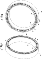
- FIG. 6 illustrates one embodiment of a completed stator 22 for a double-sided machine.
- the stator 22 could optionally be potted in a resin (e.g., epoxy) to further increase the mechanical stiffness of the stator tooth module assembly is desired.
- temporary spacers (not shown) could be used to maintain clearances between adjacent coils to permit cooling airflow if desired.
- the stator 22 could also undergo a global vacuum pressure impregnation (i.e., VPI) to further increase environmental sealing and integrity of the stator winding insulation system, especially at the end connections.
- VPI global vacuum pressure impregnation
Claims (10)
- Machine électrique (10) comprenant :un rotor (16) ; etun stator (22) comprenant une pluralité de modules de dents de stator (40) et configuré pour un passage de flux magnétique radial, lesdits modules de dents de stator (40) comprenant au moins une plaque d'extrémité (39), dans laquelle au moins l'une parmi ladite au moins une plaque d'extrémité (39) a une plaque centrale pour montage sur un empilement de stratification (30) et des extensions (42) pour montage sur un cadre de stator (50) ;dans laquelle ledit stator (22) est disposé de manière concentrique par rapport audit rotor (16) de ladite machine électrique, et chacun desdits modules de dents de stator (40) est solidarisé au cadre de stator (50) par des extensions (42) et moyens de fixation (34) respectifs,dans laquelle chaque extension (42) comprendune première partie d'extension s'étendant perpendiculairement à l'écart de ladite plaque centrale et à l'écart dudit empilement de stratification (30),une deuxième partie d'extension s'étendant à partir d'une extrémité de la première partie d'extension dans une direction parallèle décalée par rapport à ladite plaque centrale de ladite au moins une plaque terminale (39), etau moins un trou (44) dans ladite deuxième partie d'extension pour fixation du module de dents de stator (40) au cadre de stator (50).
- Machine électrique (10) selon la revendication 1, comprenant en outre :
une chemise de refroidissement (82) disposée autour de bobines conductrices (32) d'au moins l'un parmi lesdits modules de dents de stator (40), ladite chemise de refroidissement (82) portant un milieu de transfert thermique pour refroidir lesdits modules de dents de stator (40). - Machine électrique (10) selon la revendication 2, dans laquelle ledit milieu de transfert thermique est un liquide.
- Machine électrique (10) selon une quelconque revendication précédente, dans laquelle ledit rotor (16) est un rotor à un seul côté comprenant un aimant permanent (PM), et ledit aimant permanent est situé soit à l'intérieur soit sur la surface dudit rotor (16).
- Machine électrique (10) selon une quelconque revendication précédente, comprenant en outre :un rotor interne (18) ; etun rotor externe (20) ;ledit stator (22) situé entre ledit rotor interne (18) et ledit rotor externe (20),dans laquelle ledit stator (22) est un stator sans culasse, et ledit rotor interne (18) et ledit rotor externe (20) sont configurés pour porter une composante circonférentielle de flux magnétique reliant lesdits modules de dents de stator (40).
- Machine électrique (10) selon une quelconque revendication précédente, dans laquelle ledit rotor (16) est un rotor à deux côtés comprenant un aimant permanent (PM).
- Machine électrique (10) selon une quelconque revendication précédente, dans laquelle ledit rotor (16) est un rotor à deux côtés comprenant un aimant permanent (PM), ledit aimant permanent situé sur la surface dudit rotor (16).
- Machine électrique (10) selon une quelconque revendication précédente, comprenant en outre :
un moyen de raidissement (30) pour augmenter la raideur dudit stator (22). - Machine électrique (10) selon la revendication 8, dans laquelle ledit moyen de raidissement (30) est constitué d'un matériau résineux qui est configuré pour encapsuler lesdits modules de dents de stator (40).
- Machine électrique (10) selon la revendication 8 ou la revendication 9, dans laquelle ledit moyen de raidissement (30) est constitué d'au moins un support (1302) fixé à au moins certains desdits modules de dents de stator (40) et d'un anneau (54) qui est configuré pour être fixé audit au moins un support (1302), ledit au moins un support (1302) et ledit anneau (54) fournissant une raideur et une rigidité accrues audit stator (22).
Applications Claiming Priority (1)
| Application Number | Priority Date | Filing Date | Title |
|---|---|---|---|
| US11/947,052 US7839049B2 (en) | 2007-11-29 | 2007-11-29 | Stator and stator tooth modules for electrical machines |
Publications (3)
| Publication Number | Publication Date |
|---|---|
| EP2066005A2 EP2066005A2 (fr) | 2009-06-03 |
| EP2066005A3 EP2066005A3 (fr) | 2017-03-29 |
| EP2066005B1 true EP2066005B1 (fr) | 2020-08-19 |
Family
ID=40298748
Family Applications (1)
| Application Number | Title | Priority Date | Filing Date |
|---|---|---|---|
| EP08169009.1A Active EP2066005B1 (fr) | 2007-11-29 | 2008-11-13 | Stator et modules de dents statoriques pour machines électriques |
Country Status (5)
| Country | Link |
|---|---|
| US (1) | US7839049B2 (fr) |
| EP (1) | EP2066005B1 (fr) |
| CN (1) | CN101447702B (fr) |
| DK (1) | DK2066005T3 (fr) |
| ES (1) | ES2831250T3 (fr) |
Families Citing this family (49)
| Publication number | Priority date | Publication date | Assignee | Title |
|---|---|---|---|---|
| US8803354B2 (en) | 2006-12-20 | 2014-08-12 | Unimodal Systems Llc | Modular electric generator for variable speed turbines |
| EP2071213B1 (fr) * | 2007-12-11 | 2014-12-03 | General Electric Company | Réduction du bruit de la boîte de vitesse par contrôle électrique de la commande |
| CA2710706C (fr) * | 2007-12-28 | 2013-03-05 | Clean Current Power Systems Incorporated | Systeme d'alimentation en energie electrique hybride avec moteur/generateur segmente distribue |
| US7843104B2 (en) * | 2008-01-23 | 2010-11-30 | General Electric Company | Stator and stator components of dynamoelectric machines and process of inhibiting joule heating therein |
| PL2394351T3 (pl) | 2009-02-05 | 2021-05-31 | Evr Motors Ltd. | Maszyna elektryczna |
| IT1393872B1 (it) * | 2009-04-22 | 2012-05-11 | Ansaldo Ricerche S P A | Sistema di raffreddamento per motore elettrico ad alta densita' volumetrica di potenza, in particolare motore elettrico a flusso assiale |
| US8373319B1 (en) | 2009-09-25 | 2013-02-12 | Jerry Barnes | Method and apparatus for a pancake-type motor/generator |
| US20140125154A1 (en) * | 2009-12-22 | 2014-05-08 | Kress Motors, LLC | Poly gap transverse flux machine |
| WO2011100987A1 (fr) * | 2010-02-16 | 2011-08-25 | Siemens Aktiengesellschaft | Procédé d'assemblage d'une partie d'un générateur, générateur et turbine d'éolienne |
| FR2957730B1 (fr) * | 2010-03-17 | 2013-02-22 | Converteam Technology Ltd | Machine electrique tournante avec stator a bobinages concentriques |
| CN101795025A (zh) * | 2010-03-17 | 2010-08-04 | 黄山市继林机械制造有限公司 | 一种电动机的定子组件 |
| US8350440B2 (en) * | 2010-04-14 | 2013-01-08 | General Electric Company | Integrated stator flange assembly for dynamoelectric machine |
| US8492951B2 (en) | 2010-08-30 | 2013-07-23 | General Electric Company | Segmented stator assembly |
| US8319389B2 (en) | 2010-08-30 | 2012-11-27 | General Electric Company | Segmented stator assembly |
| US8274192B2 (en) | 2010-08-30 | 2012-09-25 | General Electric Company | Segmented stator assembly |
| EP2434617A1 (fr) * | 2010-09-24 | 2012-03-28 | Siemens Aktiengesellschaft | Générateur pour machine électrique |
| DE102010055030A1 (de) * | 2010-12-17 | 2012-06-21 | Cpm Compact Power Motors Gmbh | Elektromotor mit optimierter Statorstruktur |
| FI122755B (fi) * | 2011-01-26 | 2012-06-29 | Axco Motors Oy | Liitos ja liitosmenetelmä kestomagneettitahtikohteessa |
| US8400038B2 (en) | 2011-04-13 | 2013-03-19 | Boulder Wind Power, Inc. | Flux focusing arrangement for permanent magnets, methods of fabricating such arrangements, and machines including such arrangements |
| US8866362B2 (en) | 2011-10-25 | 2014-10-21 | General Electric Company | Lamination stack for an electrical machine stator |
| US20130099503A1 (en) | 2011-10-25 | 2013-04-25 | General Electric Company | Lamination stack for an electrical machine stator |
| US8941282B2 (en) | 2012-03-05 | 2015-01-27 | Siemens Energy, Inc. | Turbine generator stator core attachment technique |
| US9479014B2 (en) * | 2012-03-28 | 2016-10-25 | Acme Product Development, Ltd. | System and method for a programmable electric converter |
| US10326322B2 (en) * | 2012-08-20 | 2019-06-18 | Rensselaer Polytechnic Institute | Double-rotor flux-switching machine |
| CN103312104B (zh) * | 2013-06-24 | 2015-04-15 | 南京航空航天大学 | 双转子磁通切换永磁电机 |
| US11171533B2 (en) | 2017-01-19 | 2021-11-09 | Francis Xavier Gentile | Electric devices, generators, and motors |
| US9583989B2 (en) | 2013-09-06 | 2017-02-28 | Francis Xavier Gentile | Electric generator |
| JP6634018B2 (ja) | 2013-09-18 | 2020-01-22 | イー.ヴィー.アール. モーターズ リミテッドE.V.R. Motors Ltd. | 多極電気機械 |
| US9899886B2 (en) | 2014-04-29 | 2018-02-20 | Boulder Wind Power, Inc. | Devices and methods for magnetic flux return optimization in electromagnetic machines |
| EP3226383A1 (fr) * | 2016-03-30 | 2017-10-04 | Siemens Aktiengesellschaft | Ensemble stator destiné à un générateur électrique avec espace de logement |
| DK3252928T3 (da) * | 2016-06-03 | 2020-11-09 | Siemens Gamesa Renewable Energy As | Statorenhed med en kabelledningsindretning, generator og vindmølle med en sådan statorenhed |
| CN116317244A (zh) * | 2017-03-03 | 2023-06-23 | 通用电气再生能源技术公司 | 凸极电机 |
| DE102017206873A1 (de) * | 2017-04-24 | 2018-10-25 | Siemens Wind Power A/S | Stützstruktursegment für einen Generator einer Windturbine |
| EP3669441A4 (fr) * | 2017-08-16 | 2021-03-17 | Current Kinetics, LLC | Machines électriques submergées |
| EP3477820B1 (fr) | 2017-10-26 | 2021-02-24 | Jan-Dirk Reimers | Machine anneau électrique pour fonctionnement de l'onduleur |
| EP3503358A1 (fr) | 2017-12-21 | 2019-06-26 | Jan-Dirk Reimers | Système modulaire pour une machine électrique à anneau |
| WO2019124592A1 (fr) * | 2017-12-21 | 2019-06-27 | 장경한 | Ventilateur auto-alimenté |
| CN110120729A (zh) * | 2018-02-06 | 2019-08-13 | 上海富田电气技术有限公司 | 一种径向磁场定子无轭双转子盘式永磁同步电机 |
| DE102018205806A1 (de) * | 2018-04-17 | 2019-10-17 | Siemens Aktiengesellschaft | Stator, elektrische Maschine, Luftfahrzeug mit einer elektrischen Maschine und Verfahren zur Herstellung eines Stators |
| US20220069649A1 (en) * | 2019-01-10 | 2022-03-03 | Vestas Wind Systems A/S | A generator rotor assembly |
| CN109802539A (zh) * | 2019-01-31 | 2019-05-24 | 高宪立 | 积木式定子盘、永磁电机及其速度控制方法 |
| WO2020181322A1 (fr) * | 2019-03-08 | 2020-09-17 | FluxSystems Pty Ltd | Procédé et appareil pour refroidissement de moteur |
| CN112311175A (zh) * | 2020-05-29 | 2021-02-02 | 深圳市一吉制造有限公司 | 一种新型两定子四转子的组合节能电机 |
| CN112311178A (zh) * | 2020-05-29 | 2021-02-02 | 深圳市一吉制造有限公司 | 一种新型混波永磁节能电机 |
| CN112311176A (zh) * | 2020-05-29 | 2021-02-02 | 深圳市一吉制造有限公司 | 一种新型两定子两转子的组合节能电机 |
| CN112311174A (zh) * | 2020-05-29 | 2021-02-02 | 深圳市一吉制造有限公司 | 一种新型四定子四转子的组合节能电机 |
| CN112039235A (zh) * | 2020-07-31 | 2020-12-04 | 西安中车永电捷力风能有限公司 | 一种水冷结构集中绕组直驱永磁风力发电机定子 |
| WO2023105551A1 (fr) * | 2021-12-06 | 2023-06-15 | 三菱電機株式会社 | Machine électrique tournante et aéronef équipé de cette machine électrique tournante |
| CN114678992B (zh) * | 2022-03-18 | 2024-01-30 | 大连智鼎科技有限公司 | 一种框架结构电机及装配方法 |
Family Cites Families (20)
| Publication number | Priority date | Publication date | Assignee | Title |
|---|---|---|---|---|
| US598657A (en) * | 1898-02-08 | William beedie esson | ||
| DE746360C (de) * | 1939-09-23 | 1944-07-21 | Auto Union A G | Befestigung der Pole im Joch elektrischer Maschinen, insbesondere elektrischer Maschinen fuer Kraftfahrzeuge |
| US3602749A (en) * | 1970-02-20 | 1971-08-31 | Ernie B Esters | Dynamoelectric machine |
| DE4023791A1 (de) | 1990-07-26 | 1992-01-30 | Siemens Ag | Elektrische maschine mit einem innen- und aussenlaeufer |
| US5481143A (en) * | 1993-11-15 | 1996-01-02 | Burdick; Brian K. | Self starting brushless d.c. motor |
| AT408045B (de) | 1998-01-30 | 2001-08-27 | Schroedl Manfred Dipl Ing Dr | Elektrische maschine |
| DK173641B1 (da) * | 1998-12-15 | 2001-05-14 | Bonus Energy As | Generator, fortrinsvis til en vindmølle |
| US6590312B1 (en) | 1999-11-18 | 2003-07-08 | Denso Corporation | Rotary electric machine having a permanent magnet stator and permanent magnet rotor |
| US6717324B2 (en) * | 2001-10-15 | 2004-04-06 | Ming Yan Chen | Magnet motor device |
| US7026742B2 (en) | 2002-04-01 | 2006-04-11 | Nissan Motor Co., Ltd. | Stator mounting for a double rotor electric motor |
| GB0208565D0 (en) | 2002-04-13 | 2002-05-22 | Rolls Royce Plc | A compact electrical machine |
| US6891306B1 (en) * | 2002-04-30 | 2005-05-10 | Wavecrest Laboratories, Llc. | Rotary electric motor having both radial and axial air gap flux paths between stator and rotor segments |
| JP4050746B2 (ja) * | 2002-06-26 | 2008-02-20 | アモテック・カンパニー・リミテッド | ラジアルコアタイプダブルローター方式のBLDCモーター(BrushlessDirectCurrentMotorofRadialCoreTypeHavingaStructureofDoubleRotors) |
| US7042109B2 (en) | 2002-08-30 | 2006-05-09 | Gabrys Christopher W | Wind turbine |
| JP3901104B2 (ja) * | 2003-02-14 | 2007-04-04 | トヨタ自動車株式会社 | ステータコイルモジュールおよびその製造方法ならびに回転電機、回転電機の製造方法 |
| JP2004312845A (ja) | 2003-04-04 | 2004-11-04 | Nissan Motor Co Ltd | モータ用ステータ |
| US6924574B2 (en) | 2003-05-30 | 2005-08-02 | Wisconsin Alumni Research Foundation | Dual-rotor, radial-flux, toroidally-wound, permanent-magnet machine |
| US7154193B2 (en) | 2004-09-27 | 2006-12-26 | General Electric Company | Electrical machine with double-sided stator |
| US7154192B2 (en) | 2004-09-27 | 2006-12-26 | General Electric Company | Electrical machine with double-sided lamination stack |
| US7692357B2 (en) | 2004-12-16 | 2010-04-06 | General Electric Company | Electrical machines and assemblies including a yokeless stator with modular lamination stacks |
-
2007
- 2007-11-29 US US11/947,052 patent/US7839049B2/en active Active
-
2008
- 2008-11-13 EP EP08169009.1A patent/EP2066005B1/fr active Active
- 2008-11-13 ES ES08169009T patent/ES2831250T3/es active Active
- 2008-11-13 DK DK08169009.1T patent/DK2066005T3/da active
- 2008-11-28 CN CN2008101796357A patent/CN101447702B/zh active Active
Non-Patent Citations (1)
| Title |
|---|
| None * |
Also Published As
| Publication number | Publication date |
|---|---|
| DK2066005T3 (da) | 2020-11-23 |
| CN101447702B (zh) | 2013-03-27 |
| ES2831250T3 (es) | 2021-06-08 |
| US20090140526A1 (en) | 2009-06-04 |
| EP2066005A2 (fr) | 2009-06-03 |
| CN101447702A (zh) | 2009-06-03 |
| EP2066005A3 (fr) | 2017-03-29 |
| US7839049B2 (en) | 2010-11-23 |
Similar Documents
| Publication | Publication Date | Title |
|---|---|---|
| EP2066005B1 (fr) | Stator et modules de dents statoriques pour machines électriques | |
| US7692357B2 (en) | Electrical machines and assemblies including a yokeless stator with modular lamination stacks | |
| EP1641101B1 (fr) | Machine électrique avec stator double-face | |
| US7839048B2 (en) | Electrical machine with double-sided stator | |
| EP1641102B1 (fr) | Machine électrique avec paquet de tôles double-face | |
| US7548008B2 (en) | Electrical machine with double-sided lamination stack | |
| US7154191B2 (en) | Electrical machine with double-sided rotor | |
| CA2659824C (fr) | Segments de rotor et de stator pour generateur et moteur | |
| EP2378117A1 (fr) | Éolienne | |
| US20110241453A1 (en) | Electrical machine and method for the manufacture of stator sections therefor | |
| US8461730B2 (en) | Radial flux permanent magnet alternator with dielectric stator block | |
| CN101060258A (zh) | 一种横磁通永磁风力发电机 | |
| Qu et al. | Electrical machines and assemblies including a yokeless stator with modular lamination stacks | |
| CN201038962Y (zh) | 一种永磁风力发电机 | |
| POOLA | Design aspects of direct drive PM machines for wind power generation |
Legal Events
| Date | Code | Title | Description |
|---|---|---|---|
| PUAI | Public reference made under article 153(3) epc to a published international application that has entered the european phase |
Free format text: ORIGINAL CODE: 0009012 |
|
| AK | Designated contracting states |
Kind code of ref document: A2 Designated state(s): AT BE BG CH CY CZ DE DK EE ES FI FR GB GR HR HU IE IS IT LI LT LU LV MC MT NL NO PL PT RO SE SI SK TR |
|
| AX | Request for extension of the european patent |
Extension state: AL BA MK RS |
|
| PUAL | Search report despatched |
Free format text: ORIGINAL CODE: 0009013 |
|
| AK | Designated contracting states |
Kind code of ref document: A3 Designated state(s): AT BE BG CH CY CZ DE DK EE ES FI FR GB GR HR HU IE IS IT LI LT LU LV MC MT NL NO PL PT RO SE SI SK TR |
|
| AX | Request for extension of the european patent |
Extension state: AL BA MK RS |
|
| RIC1 | Information provided on ipc code assigned before grant |
Ipc: H02K 1/27 20060101ALN20170218BHEP Ipc: H02K 1/14 20060101AFI20170218BHEP Ipc: H02K 16/02 20060101ALI20170218BHEP |
|
| STAA | Information on the status of an ep patent application or granted ep patent |
Free format text: STATUS: REQUEST FOR EXAMINATION WAS MADE |
|
| 17P | Request for examination filed |
Effective date: 20170929 |
|
| RBV | Designated contracting states (corrected) |
Designated state(s): AT BE BG CH CY CZ DE DK EE ES FI FR GB GR HR HU IE IS IT LI LT LU LV MC MT NL NO PL PT RO SE SI SK TR |
|
| AKX | Designation fees paid |
Designated state(s): DE DK ES |
|
| AXX | Extension fees paid |
Extension state: MK Extension state: RS Extension state: BA Extension state: AL |
|
| STAA | Information on the status of an ep patent application or granted ep patent |
Free format text: STATUS: EXAMINATION IS IN PROGRESS |
|
| 17Q | First examination report despatched |
Effective date: 20181107 |
|
| GRAP | Despatch of communication of intention to grant a patent |
Free format text: ORIGINAL CODE: EPIDOSNIGR1 |
|
| STAA | Information on the status of an ep patent application or granted ep patent |
Free format text: STATUS: GRANT OF PATENT IS INTENDED |
|
| RIC1 | Information provided on ipc code assigned before grant |
Ipc: H02K 16/02 20060101ALI20191002BHEP Ipc: H02K 1/14 20060101AFI20191002BHEP Ipc: H02K 1/27 20060101ALN20191002BHEP |
|
| INTG | Intention to grant announced |
Effective date: 20191031 |
|
| GRAJ | Information related to disapproval of communication of intention to grant by the applicant or resumption of examination proceedings by the epo deleted |
Free format text: ORIGINAL CODE: EPIDOSDIGR1 |
|
| STAA | Information on the status of an ep patent application or granted ep patent |
Free format text: STATUS: EXAMINATION IS IN PROGRESS |
|
| GRAP | Despatch of communication of intention to grant a patent |
Free format text: ORIGINAL CODE: EPIDOSNIGR1 |
|
| STAA | Information on the status of an ep patent application or granted ep patent |
Free format text: STATUS: GRANT OF PATENT IS INTENDED |
|
| INTC | Intention to grant announced (deleted) | ||
| RIC1 | Information provided on ipc code assigned before grant |
Ipc: H02K 1/14 20060101AFI20200225BHEP Ipc: H02K 16/02 20060101ALI20200225BHEP Ipc: H02K 1/27 20060101ALN20200225BHEP |
|
| INTG | Intention to grant announced |
Effective date: 20200311 |
|
| GRAS | Grant fee paid |
Free format text: ORIGINAL CODE: EPIDOSNIGR3 |
|
| GRAA | (expected) grant |
Free format text: ORIGINAL CODE: 0009210 |
|
| STAA | Information on the status of an ep patent application or granted ep patent |
Free format text: STATUS: THE PATENT HAS BEEN GRANTED |
|
| AK | Designated contracting states |
Kind code of ref document: B1 Designated state(s): DE DK ES |
|
| REG | Reference to a national code |
Ref country code: DE Ref legal event code: R096 Ref document number: 602008063155 Country of ref document: DE |
|
| REG | Reference to a national code |
Ref country code: DE Ref legal event code: R082 Ref document number: 602008063155 Country of ref document: DE Representative=s name: ZIMMERMANN & PARTNER PATENTANWAELTE MBB, DE Ref country code: DK Ref legal event code: T3 Effective date: 20201117 |
|
| REG | Reference to a national code |
Ref country code: DE Ref legal event code: R097 Ref document number: 602008063155 Country of ref document: DE |
|
| REG | Reference to a national code |
Ref country code: ES Ref legal event code: FG2A Ref document number: 2831250 Country of ref document: ES Kind code of ref document: T3 Effective date: 20210608 |
|
| PLBE | No opposition filed within time limit |
Free format text: ORIGINAL CODE: 0009261 |
|
| STAA | Information on the status of an ep patent application or granted ep patent |
Free format text: STATUS: NO OPPOSITION FILED WITHIN TIME LIMIT |
|
| 26N | No opposition filed |
Effective date: 20210520 |
|
| P01 | Opt-out of the competence of the unified patent court (upc) registered |
Effective date: 20230530 |
|
| REG | Reference to a national code |
Ref country code: DE Ref legal event code: R082 Ref document number: 602008063155 Country of ref document: DE Representative=s name: ZIMMERMANN & PARTNER PATENTANWAELTE MBB, DE Ref country code: DE Ref legal event code: R082 Ref document number: 602008063155 Country of ref document: DE Ref country code: DE Ref legal event code: R081 Ref document number: 602008063155 Country of ref document: DE Owner name: GENERAL ELECTRIC RENOVABLES ESPANA, S.L., ES Free format text: FORMER OWNER: GENERAL ELECTRIC COMPANY, SCHENECTADY, NY, US |
|
| PGFP | Annual fee paid to national office [announced via postgrant information from national office to epo] |
Ref country code: ES Payment date: 20231201 Year of fee payment: 16 |
|
| PGFP | Annual fee paid to national office [announced via postgrant information from national office to epo] |
Ref country code: DK Payment date: 20231019 Year of fee payment: 16 Ref country code: DE Payment date: 20231019 Year of fee payment: 16 |
|
| REG | Reference to a national code |
Ref country code: DE Ref legal event code: R082 Ref document number: 602008063155 Country of ref document: DE Representative=s name: ZIMMERMANN & PARTNER PATENTANWAELTE MBB, DE |