EP2066005A2 - Stator and stator tooth modules for electrical machines - Google Patents
Stator and stator tooth modules for electrical machines Download PDFInfo
- Publication number
- EP2066005A2 EP2066005A2 EP08169009A EP08169009A EP2066005A2 EP 2066005 A2 EP2066005 A2 EP 2066005A2 EP 08169009 A EP08169009 A EP 08169009A EP 08169009 A EP08169009 A EP 08169009A EP 2066005 A2 EP2066005 A2 EP 2066005A2
- Authority
- EP
- European Patent Office
- Prior art keywords
- stator
- rotor
- electrical machine
- stator tooth
- tooth modules
- Prior art date
- Legal status (The legal status is an assumption and is not a legal conclusion. Google has not performed a legal analysis and makes no representation as to the accuracy of the status listed.)
- Granted
Links
- 230000004907 flux Effects 0.000 claims abstract description 11
- 230000005291 magnetic effect Effects 0.000 claims abstract description 10
- 238000001816 cooling Methods 0.000 claims description 10
- 239000007788 liquid Substances 0.000 claims 1
- 239000012260 resinous material Substances 0.000 claims 1
- 239000003302 ferromagnetic material Substances 0.000 description 13
- 238000003475 lamination Methods 0.000 description 12
- 125000006850 spacer group Chemical group 0.000 description 6
- XLYOFNOQVPJJNP-UHFFFAOYSA-N water Substances O XLYOFNOQVPJJNP-UHFFFAOYSA-N 0.000 description 6
- RYGMFSIKBFXOCR-UHFFFAOYSA-N Copper Chemical group [Cu] RYGMFSIKBFXOCR-UHFFFAOYSA-N 0.000 description 5
- 230000004323 axial length Effects 0.000 description 5
- 229910000975 Carbon steel Inorganic materials 0.000 description 4
- 229910052802 copper Inorganic materials 0.000 description 4
- 239000010949 copper Substances 0.000 description 4
- 239000010935 stainless steel Substances 0.000 description 4
- 229910001220 stainless steel Inorganic materials 0.000 description 4
- 229910000851 Alloy steel Inorganic materials 0.000 description 3
- 229910001141 Ductile iron Inorganic materials 0.000 description 3
- 230000008901 benefit Effects 0.000 description 3
- 239000010962 carbon steel Substances 0.000 description 3
- 230000033001 locomotion Effects 0.000 description 3
- 239000000463 material Substances 0.000 description 3
- 229910000831 Steel Inorganic materials 0.000 description 2
- 230000002528 anti-freeze Effects 0.000 description 2
- 238000013459 approach Methods 0.000 description 2
- 230000009286 beneficial effect Effects 0.000 description 2
- 230000006835 compression Effects 0.000 description 2
- 238000007906 compression Methods 0.000 description 2
- 230000005611 electricity Effects 0.000 description 2
- 238000005470 impregnation Methods 0.000 description 2
- 238000009413 insulation Methods 0.000 description 2
- XEEYBQQBJWHFJM-UHFFFAOYSA-N iron Substances [Fe] XEEYBQQBJWHFJM-UHFFFAOYSA-N 0.000 description 2
- 229910052742 iron Inorganic materials 0.000 description 2
- 238000000034 method Methods 0.000 description 2
- 238000012986 modification Methods 0.000 description 2
- 230000004048 modification Effects 0.000 description 2
- 239000011347 resin Substances 0.000 description 2
- 229920005989 resin Polymers 0.000 description 2
- 239000010959 steel Substances 0.000 description 2
- 230000001360 synchronised effect Effects 0.000 description 2
- OKTJSMMVPCPJKN-UHFFFAOYSA-N Carbon Chemical compound [C] OKTJSMMVPCPJKN-UHFFFAOYSA-N 0.000 description 1
- 239000004593 Epoxy Substances 0.000 description 1
- 229920002430 Fibre-reinforced plastic Polymers 0.000 description 1
- XAGFODPZIPBFFR-UHFFFAOYSA-N aluminium Chemical compound [Al] XAGFODPZIPBFFR-UHFFFAOYSA-N 0.000 description 1
- 229910052782 aluminium Inorganic materials 0.000 description 1
- 230000000712 assembly Effects 0.000 description 1
- 238000000429 assembly Methods 0.000 description 1
- 230000005540 biological transmission Effects 0.000 description 1
- 238000005219 brazing Methods 0.000 description 1
- 239000004020 conductor Substances 0.000 description 1
- 239000002826 coolant Substances 0.000 description 1
- 239000012809 cooling fluid Substances 0.000 description 1
- 238000009826 distribution Methods 0.000 description 1
- 230000009977 dual effect Effects 0.000 description 1
- 238000005516 engineering process Methods 0.000 description 1
- 230000007613 environmental effect Effects 0.000 description 1
- 230000005294 ferromagnetic effect Effects 0.000 description 1
- 239000011151 fibre-reinforced plastic Substances 0.000 description 1
- 238000009434 installation Methods 0.000 description 1
- 239000000203 mixture Substances 0.000 description 1
- 238000010248 power generation Methods 0.000 description 1
- 238000005086 pumping Methods 0.000 description 1
- 230000000717 retained effect Effects 0.000 description 1
- 238000007789 sealing Methods 0.000 description 1
- 238000004804 winding Methods 0.000 description 1
Images


Classifications
-
- H—ELECTRICITY
- H02—GENERATION; CONVERSION OR DISTRIBUTION OF ELECTRIC POWER
- H02K—DYNAMO-ELECTRIC MACHINES
- H02K1/00—Details of the magnetic circuit
- H02K1/06—Details of the magnetic circuit characterised by the shape, form or construction
- H02K1/12—Stationary parts of the magnetic circuit
- H02K1/14—Stator cores with salient poles
- H02K1/146—Stator cores with salient poles consisting of a generally annular yoke with salient poles
- H02K1/148—Sectional cores
-
- H—ELECTRICITY
- H02—GENERATION; CONVERSION OR DISTRIBUTION OF ELECTRIC POWER
- H02K—DYNAMO-ELECTRIC MACHINES
- H02K1/00—Details of the magnetic circuit
- H02K1/06—Details of the magnetic circuit characterised by the shape, form or construction
- H02K1/12—Stationary parts of the magnetic circuit
- H02K1/14—Stator cores with salient poles
-
- H—ELECTRICITY
- H02—GENERATION; CONVERSION OR DISTRIBUTION OF ELECTRIC POWER
- H02K—DYNAMO-ELECTRIC MACHINES
- H02K16/00—Machines with more than one rotor or stator
- H02K16/02—Machines with one stator and two or more rotors
-
- H—ELECTRICITY
- H02—GENERATION; CONVERSION OR DISTRIBUTION OF ELECTRIC POWER
- H02K—DYNAMO-ELECTRIC MACHINES
- H02K3/00—Details of windings
- H02K3/46—Fastening of windings on the stator or rotor structure
- H02K3/52—Fastening salient pole windings or connections thereto
- H02K3/521—Fastening salient pole windings or connections thereto applicable to stators only
- H02K3/522—Fastening salient pole windings or connections thereto applicable to stators only for generally annular cores with salient poles
-
- H—ELECTRICITY
- H02—GENERATION; CONVERSION OR DISTRIBUTION OF ELECTRIC POWER
- H02K—DYNAMO-ELECTRIC MACHINES
- H02K7/00—Arrangements for handling mechanical energy structurally associated with dynamo-electric machines, e.g. structural association with mechanical driving motors or auxiliary dynamo-electric machines
- H02K7/18—Structural association of electric generators with mechanical driving motors, e.g. with turbines
- H02K7/1807—Rotary generators
- H02K7/1823—Rotary generators structurally associated with turbines or similar engines
- H02K7/183—Rotary generators structurally associated with turbines or similar engines wherein the turbine is a wind turbine
- H02K7/1838—Generators mounted in a nacelle or similar structure of a horizontal axis wind turbine
-
- H—ELECTRICITY
- H02—GENERATION; CONVERSION OR DISTRIBUTION OF ELECTRIC POWER
- H02K—DYNAMO-ELECTRIC MACHINES
- H02K1/00—Details of the magnetic circuit
- H02K1/06—Details of the magnetic circuit characterised by the shape, form or construction
- H02K1/22—Rotating parts of the magnetic circuit
- H02K1/27—Rotor cores with permanent magnets
- H02K1/2706—Inner rotors
- H02K1/272—Inner rotors the magnetisation axis of the magnets being perpendicular to the rotor axis
- H02K1/274—Inner rotors the magnetisation axis of the magnets being perpendicular to the rotor axis the rotor consisting of two or more circumferentially positioned magnets
- H02K1/2753—Inner rotors the magnetisation axis of the magnets being perpendicular to the rotor axis the rotor consisting of two or more circumferentially positioned magnets the rotor consisting of magnets or groups of magnets arranged with alternating polarity
- H02K1/276—Magnets embedded in the magnetic core, e.g. interior permanent magnets [IPM]
- H02K1/2766—Magnets embedded in the magnetic core, e.g. interior permanent magnets [IPM] having a flux concentration effect
- H02K1/2773—Magnets embedded in the magnetic core, e.g. interior permanent magnets [IPM] having a flux concentration effect consisting of tangentially magnetized radial magnets
-
- H—ELECTRICITY
- H02—GENERATION; CONVERSION OR DISTRIBUTION OF ELECTRIC POWER
- H02K—DYNAMO-ELECTRIC MACHINES
- H02K2201/00—Specific aspects not provided for in the other groups of this subclass relating to the magnetic circuits
- H02K2201/15—Sectional machines
-
- H—ELECTRICITY
- H02—GENERATION; CONVERSION OR DISTRIBUTION OF ELECTRIC POWER
- H02K—DYNAMO-ELECTRIC MACHINES
- H02K2213/00—Specific aspects, not otherwise provided for and not covered by codes H02K2201/00 - H02K2211/00
- H02K2213/12—Machines characterised by the modularity of some components
-
- Y—GENERAL TAGGING OF NEW TECHNOLOGICAL DEVELOPMENTS; GENERAL TAGGING OF CROSS-SECTIONAL TECHNOLOGIES SPANNING OVER SEVERAL SECTIONS OF THE IPC; TECHNICAL SUBJECTS COVERED BY FORMER USPC CROSS-REFERENCE ART COLLECTIONS [XRACs] AND DIGESTS
- Y02—TECHNOLOGIES OR APPLICATIONS FOR MITIGATION OR ADAPTATION AGAINST CLIMATE CHANGE
- Y02E—REDUCTION OF GREENHOUSE GAS [GHG] EMISSIONS, RELATED TO ENERGY GENERATION, TRANSMISSION OR DISTRIBUTION
- Y02E10/00—Energy generation through renewable energy sources
- Y02E10/70—Wind energy
- Y02E10/72—Wind turbines with rotation axis in wind direction
Definitions
- the invention relates generally to radial flux electrical machines and more specifically to an electrical machine with a stator having modular stator teeth.
- Electrical machines i.e. generators and motors
- Electrical machines for power generation, transmission and distribution provide power for industrial, business and residential requirements.
- wind turbines are used to convert the kinetic energy in the wind into mechanical power. This mechanical power may be used for specific tasks (such as grinding grain or pumping water) or a generator may convert this mechanical power into electricity.
- a wind turbine usually includes an aerodynamic mechanism for converting the movement of air into a mechanical motion, which is then converted with a generator into electrical power.
- the majority of commercially available wind turbines utilize geared drive trains to connect the turbine blades to the wind generators.
- the wind turns the turbine blades, which rotate a shaft, which feeds into a gear-box and then connects to a wind generator and makes electricity.
- the geared drive aims to increase the velocity of the mechanical motion.
- the drawback of a geared drive is that it reduces the reliability of the wind turbine and increases the noise and cost of the wind turbine.
- a few wind turbines utilizing direct-drive generators are also commercially available. Due to the low speed operation (due to the absence of a gearbox), these generators tend to be very large in diameter. The large diameters of the direct drive generators present daunting transportation and assembly challenges, both at the factories and at the wind turbine installation sites. As the wind turbine industry matures and technology improves, larger power ratings will be required to continue the downward push in the cost of energy. Standard power ratings for land-based turbines are expected to be 3 MW or greater in the next few years, and the offshore turbines are expected to be 5 MW or greater.
- stator In some double-sided direct-drive configurations the stator is fixed by the bolts through the holes in the stator yoke (e.g., see U.S. Patent No. 7,154,192 ).
- the stator yoke is useful, for mechanical reasons, to mechanically link all the poles together and to fix the whole stator to a frame.
- the drawback in these configurations is that stator yoke adds more material mass into the stator and occupies additional space so that the inner airgap diameter is reduced due to the limited overall generator outside diameter.
- the resultant generator is heavy and expensive and requires expensive cooling methods.
- stator configurations resulting in smaller overall size for generators/motors, requiring less material and less expensive cooling techniques, without compromising on the power ratings.
- an electrical machine comprising a rotor and a stator.
- the stator includes a plurality of stator tooth modules configured for radial magnetic flux flow.
- the stator tooth modules include at least one end plate, and the end plates have extensions for mounting onto a stator frame.
- the stator is concentrically disposed in relation to the rotor of the electrical machine.
- a wind turbine having an electrical generator comprising a rotor and a stator.
- the stator includes a plurality of stator tooth modules.
- the stator tooth modules include at least one end plate, and the end plates have extensions for mounting onto a stator frame.
- the stator is concentrically disposed in relation to the rotor of the electrical generator.
- the present invention includes different embodiments for modular-pole double-sided or single-sided electrical machines with yokeless stators that are particularly useful for direct-drive or medium-speed geared wind turbines and ship propulsion motors.
- the different configurations for wind turbines described herein below are based upon double-sided or single-sided, radial-flux, permanent magnet electrical machines.
- permanent magnet (PM) machines are described and shown for the purpose of illustration, other electrical machines such as wound field synchronous machines, or switched or synchronous reluctance machines can alternatively be used.
- PM permanent magnet
- These configurations contribute towards achieving cost-effective wind turbines of increased power ratings (greater than 2.0 MW) and are especially advantageous for land-based applications where the outside diameter may be constrained by transportation limitations.
- power levels of greater than 2.5MW are specifically stated, this invention is equally applicable and can be as beneficial for wind turbines of all sizes, including small-medium size wind turbines in the 50kW to 500kW range and larger wind turbines of 3MW and greater.
- FIG. 1 is a diagrammatic representation of a sectional view of a wind turbine 10 as an exemplary electrical machine.
- the wind turbine 10 includes a nacelle 12 and an exemplary embodiment of a direct-drive double-sided PM generator 14.
- the PM generator 14 of the wind turbine 10 can include at least two concentric air gaps (not shown in FIG. 1 and discussed later in reference to FIG. 2 ), thereby effectively converting the PM generator 14 into two concentric generators.
- the PM generator 14 can produce considerably more power output than as a single-sided generator.
- a 2 MW single-sided generator might be replaced by a double-sided generator capable of producing 3MW to 3.6 MW for the same total diameter and axial length.
- a 3 MW single-sided PM generator having a diameter of 6 meters might be replaced with a double-sided generator of the same axial length with only a 4.3 meter diameter, thereby enabling land-transportation of the entire generator as one unit.
- the yokeless configuration of these generators achieves cost-effective wind turbines of increased power ratings (greater than 2.5MW) based upon direct-drive generators that have a desirable physical envelope.
- the PM generator 14 is mounted on a nacelle main frame 110 via a main shaft and bearing assembly 112.
- the nacelle main frame 110 is further mounted to a tower 140 through a conventional yaw bearing and gear drive system (not shown). More detailed features of the PM generator 14 are described herein below with reference to FIG. 2 .
- a rotor blade hub 116 connects the wind turbine rotor blades 118 to the PM generator 14.
- a rotor hub cover 120 contains the wind turbine rotor blades 118 and other turbine rotor components.
- a nacelle cover 122 is also provided and it typically protects the components inside the nacelle from the environment (e.g., wind, rain, snow, etc.).
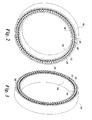
- FIGS. 2 and 3 illustrate the front end and rear end views respectively, of one embodiment of the modular-pole wind turbine generator 14.
- the generator 14 in FIGS. 2 and 3 includes a rotor 16 with an inner rotor portion 18 and an outer rotor portion 20, and a double-sided yokeless stator 22.
- the yokeless stator 22 is also concentrically disposed between the inner rotor portion 18 and the outer rotor portion 20 of the wind turbine generator 14.
- the yoke or back-iron of a stator in a conventional machine is the section of core steel that is designed to carry the circumferential component of magnetic flux that links the stator teeth.
- the yokeless stator 22 is seen to have no yoke or back-iron section, therefore the inner and outer rotor portions 18 and 20 are designed to carry the circumferential component of the magnetic flux linking the stator teeth.
- the generator 14 further comprises a stator frame 50 (shown in FIG. 5 ).
- the yokeless stator 22 is disposed between two rotating rotor portions 18, 20 inside and outside of the stator, respectively.
- the rotor portions 18, 20 are shown as, but not limited to, permanent magnet rotors.
- FIGS. 4a and 4b show a view of one stator tooth module 40 for the yokeless stator 22 and its exploded view.
- the stator 22 includes multiple stator tooth modules 40, in which one or more coils 32 are wound around a respective modular lamination stack 30. In some embodiments, it may be desirable to have a ground-wall insulation layer between the stator coil 32 and the lamination stack 30. Coils 32 may have one or more leads 33 which extend out from the coil and beyond extension 42.
- each respective stator tooth module 40 as shown in FIG. 4a , includes stack compression bolts 34 and nuts for compressing the respective modular lamination stack 30, and pre-insulated conductor wire 32.
- each stator tooth module 40 includes an I-shaped lamination stack 30. Though two bolts 34 are shown in FIG. 4 , additional bolts may be used for each lamination stack 30 to increase mechanical stiffness depending on system requirements.
- the stator tooth module 40 further includes end plates 38 and 39 as shown in FIG. 4a , and bolts (not shown) or other fastening means can be used to attach end plate 39 and the respective stator tooth module 40 to the stator frame 50.
- End plates 38, 39 can have a similar shape as the lamination stack 30, and in some embodiments, have slightly smaller dimensions than lamination stack 30. The slightly smaller dimensions would permit the edges of the end plates 38, 39 to be recessed from the lamination stack, and could prove beneficial at the air gap surfaces.
- the end plates 38, 39 can have matching holes with respect to lamination stack 30.
- End plate 39 includes extensions 42 with integral holes 44 that can be used, with suitable fasteners (e.g., bolts) to fasten the stator tooth module 40 to the stator frame 50.
- one extension 42 has one hole 44, but more than one hole could be used per extension.
- two or more holes could be placed in each extension 42 for use in fastening (via bolts or other suitable fasteners) end plate 39 to the stator frame 50.
- Each stator tooth module 40 can under go a vacuum pressure impregnation (VPI) of suitable insulating resin common to large electrical machines prior to mounting.
- the end plates 38, 39 can be stamped or cut, and then press formed from sheet, plate, or bar stock of either a non-ferromagnetic material such as 300 series stainless steel or a ferromagnetic material such as carbon steel or low-alloy steel.
- the end plates 38, 39 can be cast from ductile iron.
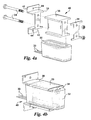
- FIG. 5 illustrates one embodiment of a stator frame 50 partially populated with stator tooth modules 40.
- the stator frame 50 can be fabricated from steel or cast ductile iron, or other suitable materials.
- a series of holes 52 are arranged in a circumferential pattern and form lead windows as well as passageways for optional axial air flow for cooling.
- the leads 33 from the stator coil 32 can be routed through these windows or holes 52.
- the leads can extend through these windows and allow connection to be made on the "back" side of stator frame 50.
- the end plates 39 are of a ferromagnetic material, then preferably one or more spacer rings 54 may be located concentrically with the stator frame 50 to prevent substantial magnetic flux from circulating through the frame 50.
- the spacer rings 54 may be formed of non-ferromagnetic material (e.g., stainless steel, aluminum, fiber-reinforced plastic), and have holes aligned with the holes 44 located on stator tooth module extensions 42 so that the stator tooth modules 40 may be rigidly attached to stator frame 50.
- mounting bolts (not shown) may be formed of non-ferromagnetic material and can be used to attach stator tooth modules 40 through spacer rings 54 to stator frame 50. If the end plates 39 and/or the stator frame 50 are of a non-ferromagnetic material, then the one or more spacer rings 54 may not be required.
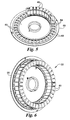
- FIG. 6 illustrates one embodiment of a completed stator 22 for a double-sided machine.
- the stator 22 could optionally be potted in a resin (e.g., epoxy) to further increase the mechanical stiffness of the stator tooth module assembly is desired.
- temporary spacers (not shown) could be used to maintain clearances between adjacent coils to permit cooling airflow if desired.
- the stator 22 could also undergo a global vacuum pressure impregnation (i.e., VPI) to further increase environmental sealing and integrity of the stator winding insulation system, especially at the end connections.
- VPI global vacuum pressure impregnation
- FIG. 7 illustrates the "back" side or connection side of the stator 22 with one example of a frame housing.
- the coil connections, via leads 33, can be made via brazing (or other suitable methods) to a combination of each other and copper rings (not shown) particular to the number of phases, poles and circuits desired or required by the specific application.
- the stator 22 has 36 stator tooth modules 40 and would preferably be used in conjunction with a 24-pole rotor to provide 1 ⁇ 2 slots per pole per phase.
- a larger and/or slower electrical machine may have more poles and stator tooth modules, for example, for a 1 ⁇ 2 slots per pole per phase configuration an electrical machine may have 96 slots (stator tooth modules), 64 poles, and 3 phases.
- Alternative embodiments can include, but are not limited to, 2/5 slots per pole per phase (e.g., 96 slots (stator tooth modules), 80 poles, and 3 phases) and 2/7 slots per pole per phase (e.g., 96 slots (stator tooth modules), 112 poles, and 3 phases).
- 2/5 slots per pole per phase e.g., 96 slots (stator tooth modules), 80 poles, and 3 phases
- 2/7 slots per pole per phase e.g., 96 slots (stator tooth modules), 112 poles, and 3 phases.
- FIG. 8 illustrates a stator tooth coil module having water jacket cooling.
- the water jacket 82 can comprise copper tubing that is wrapped around the insulated stator coil 32.
- the copper tubing could be wrapped in a single spiral, a parallel spiral, or other configurations.
- the mid-point of the copper tubing could be bent 180 degrees such that the inflow and outflow ends 84 of the tubing are adjacent and parallel to each other.
- the spiral wrapping of the tubing around the stator coil could start at the mid-point.
- the thermal cooling medium that circulates in jacket 82 could be water, antifreeze, a water/antifreeze mix or any other suitable cooling fluid.
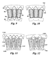
- FIGS. 9-12 illustrate partial, cross-sectional views of several embodiments of the present invention having alternative rotor configurations. Each of these embodiments may or may not be used with the optional water jacket cooling (as illustrated in FIG. 8 ).
- FIG. 9 illustrates a double-sided configuration having dual interior permanent magnet (IPM) rotors 92, 94 and two airgaps 96, 98.
- FIG. 10 illustrates a single-sided configuration having a single IPM rotor 102 and one airgap 106.
- the stator yoke can be formed from a separate stack of laminations that are compressed and bolted, either directly or indirectly, to the stator frame 50.
- the rotor 102 of FIG. 10 could be located on the inside or outside (as shown) of the stator. Although the stator (as shown in the embodiments of Figures 10-12 ) is no longer yokeless, many of the benefits of the stator tooth modules would still be retained.
- FIG. 11 illustrates a single-sided configuration having a single IPM rotor 1102 and one airgap 1106.
- the stator yoke is integrated into the stator tooth module by extending the tooth "overhangs" such that adjacent stator tooth modules mate along approximately a radial interface line with little to no clearance.
- the tooth overhangs 1104 are extended (compared to the embodiments shown in FIGS. 9 and 10 ) in the radial direction to accommodate the magnetic flux that is shared between teeth and that flows in a predominantly circumferential direction (indicated by 1107).
- FIG. 12 illustrates a similar single-sided configuration to the one shown in FIG. 11 .
- rotor 1202 is of the surface mounted permanent magnet type, as opposed to IPM type shown in FIGS. 9-11 .
- the rotors could be of the surface mount type, the interior permanent magnet type or combinations thereof.
- the rotors 1102 and 1202 of FIGs. 11 and 12 respectively could be located on the inside or outside (as shown) of the stator.
- FIG. 13 illustrates another embodiment of the stator tooth module.
- end plate 38 (see FIGS. 4a and 4b ) is replaced with end plate 1302.
- End plate 1302 is configured so that a stiffening ring (not shown) may be attached to the ends thereof.
- end plate 1302 can be preferably stamped or cut, and then press formed from sheet, plate, or bar stock of either a non-ferromagnetic material such as 300 series stainless steel or a ferromagnetic material such as carbon steel or low-alloy steel.
- the end plate 1302 can be cast from, for example, ductile iron.
- the stiffening ring is preferably formed of a non-ferromagnetic material and can be attached with suitable fasteners (e.g., non-magnetic bolts) via through holes 1304.
- suitable fasteners e.g., non-magnetic bolts
- the stiffening ring, via endplates 1302, would impart additional hoop, radial and circumferential stiffness to the stator assembly. This could enable stator assemblies of increased axial stack length and/or higher slot and pole numbers.
- the stiffening ring can be attached via insulated bolts to prevent induced circulating currents, and is preferably formed of a non-ferromagnetic material to prevent additional circulating (i.e., leakage) magnetic flux that could link the stator coils.
- the stiffening ring can also be of a ferromagnetic material such as carbon or low-alloy steel if the end plate 1302 is of a non-ferromagnetic material and/or non-ferromagnetic spacers are placed between the stiffening ring and the end plate 1302.
- the yokeless modular stator results in a smaller generator compared to a double-sided generator with a stator yoke. Since the stator yoke is removed, the inner airgap diameter may be enlarged for a given constant outer rotor outer diameter. Therefore, the inner rotor can produce more torque and power, which permits a shorter stack for a given power generator. And therefore, the overall generator length may be shorter. In some embodiments, the equivalent airgaps for both the inner and outer airgaps are reduced. This is advantageous since for a given airgap flux density, thinner permanent magnets may be used.
Abstract
Description
- The invention relates generally to radial flux electrical machines and more specifically to an electrical machine with a stator having modular stator teeth.
- Electrical machines, i.e. generators and motors, are devices that transform mechanical power into electrical power, and vice-versa. Electrical machines for power generation, transmission and distribution provide power for industrial, business and residential requirements. For example, wind turbines are used to convert the kinetic energy in the wind into mechanical power. This mechanical power may be used for specific tasks (such as grinding grain or pumping water) or a generator may convert this mechanical power into electricity. A wind turbine usually includes an aerodynamic mechanism for converting the movement of air into a mechanical motion, which is then converted with a generator into electrical power.
- The majority of commercially available wind turbines utilize geared drive trains to connect the turbine blades to the wind generators. The wind turns the turbine blades, which rotate a shaft, which feeds into a gear-box and then connects to a wind generator and makes electricity. The geared drive aims to increase the velocity of the mechanical motion. The drawback of a geared drive is that it reduces the reliability of the wind turbine and increases the noise and cost of the wind turbine.
- A few wind turbines utilizing direct-drive generators are also commercially available. Due to the low speed operation (due to the absence of a gearbox), these generators tend to be very large in diameter. The large diameters of the direct drive generators present formidable transportation and assembly challenges, both at the factories and at the wind turbine installation sites. As the wind turbine industry matures and technology improves, larger power ratings will be required to continue the downward push in the cost of energy. Standard power ratings for land-based turbines are expected to be 3 MW or greater in the next few years, and the offshore turbines are expected to be 5 MW or greater.
- For the wind turbines to evolve to higher power ratings, conventional approaches typically include an increase in the direct-drive generator diameter or axial (stack) length. Increasing the diameter is preferred from a purely generator electromagnetic perspective, but is not attractive from the transportation, frame, and assembly perspectives, especially for land-based turbines. Increasing the axial length of the generators, while maintaining the diameter to be less than approximately 4 meters, alleviates the land-based transportation issue, but results in complex and costly frame structures with long axial lengths.
- In some double-sided direct-drive configurations the stator is fixed by the bolts through the holes in the stator yoke (e.g., see
U.S. Patent No. 7,154,192 ). The stator yoke is useful, for mechanical reasons, to mechanically link all the poles together and to fix the whole stator to a frame. The drawback in these configurations is that stator yoke adds more material mass into the stator and occupies additional space so that the inner airgap diameter is reduced due to the limited overall generator outside diameter. The resultant generator is heavy and expensive and requires expensive cooling methods. - Accordingly, there is a need for stator configurations resulting in smaller overall size for generators/motors, requiring less material and less expensive cooling techniques, without compromising on the power ratings.
- Briefly, in accordance with one embodiment of the present invention, an electrical machine comprising a rotor and a stator is provided. The stator includes a plurality of stator tooth modules configured for radial magnetic flux flow. The stator tooth modules include at least one end plate, and the end plates have extensions for mounting onto a stator frame. The stator is concentrically disposed in relation to the rotor of the electrical machine.
- In accordance with another aspect, a wind turbine having an electrical generator comprising a rotor and a stator is provided. The stator includes a plurality of stator tooth modules. The stator tooth modules include at least one end plate, and the end plates have extensions for mounting onto a stator frame. The stator is concentrically disposed in relation to the rotor of the electrical generator.
- Various features, aspects, and advantages of the present invention will become better understood when the following detailed description is read with reference to the accompanying drawings in which like characters represent like parts throughout the drawings, wherein:
-
FIG. 1 illustrates a sectional view of a wind turbine including an exemplary direct-drive double-sided permanent magnet (PM) generator according to one embodiment; -
FIG. 2 illustrates a perspective front end view of the direct-drive double-sided permanent magnet (PM) generator ofFIG. 1 with a yokeless stator; -
FIG. 3 illustrates a perspective rear end view of the direct-drive double-sided permanent magnet (PM) generator ofFIG. 1 with a yokeless stator; -
FIG. 4a illustrates an exploded view of an exemplary embodiment for the yokeless stator ofFIG. 2 and FIG. 3 with one modular lamination stack; -
FIG. 4b illustrates a perspective view of an exemplary embodiment for the yokeless stator ofFIG. 2 and FIG. 3 with one modular lamination stack; -
FIG. 5 illustrates a perspective view of an exemplary embodiment of a stator assembly that is partially populated with stator tooth modules; -
FIG. 6 illustrates a perspective view of an exemplary embodiment of a stator assembly shown fully populated with stator tooth modules; -
FIG. 7 illustrates a perspective view of an exemplary embodiment showing the connection side of a stator assembly; -
FIG. 8 illustrates another exemplary embodiment of the stator tooth module incorporating a cooling jacket; -
FIG. 9 illustrates a cross-sectional view of an exemplary embodiment of an electrical machine in a double-sided configuration; -
FIG. 10 illustrates a cross-sectional view of another exemplary embodiment of an electrical machine in a single-sided configuration; -
FIG. 11 illustrates a cross-sectional view of another exemplary embodiment of an electrical machine in a single-sided configuration having extended stator tooth overhangs; -
FIG. 12 illustrates a cross-sectional view of another exemplary embodiment of an electrical machine in a single-sided configuration having extended stator tooth overhangs and a surface mounted permanent magnet rotor; -
FIG. 13 illustrates a perspective view of another exemplary embodiment of a stator tooth module having a stiffening bracket located on the opposite side from the stator frame mounting bracket. - The present invention includes different embodiments for modular-pole double-sided or single-sided electrical machines with yokeless stators that are particularly useful for direct-drive or medium-speed geared wind turbines and ship propulsion motors. The different configurations for wind turbines described herein below are based upon double-sided or single-sided, radial-flux, permanent magnet electrical machines. Although permanent magnet (PM) machines are described and shown for the purpose of illustration, other electrical machines such as wound field synchronous machines, or switched or synchronous reluctance machines can alternatively be used. These configurations contribute towards achieving cost-effective wind turbines of increased power ratings (greater than 2.0 MW) and are especially advantageous for land-based applications where the outside diameter may be constrained by transportation limitations. Although power levels of greater than 2.5MW are specifically stated, this invention is equally applicable and can be as beneficial for wind turbines of all sizes, including small-medium size wind turbines in the 50kW to 500kW range and larger wind turbines of 3MW and greater.
- Turning now to the figures,
FIG. 1 is a diagrammatic representation of a sectional view of awind turbine 10 as an exemplary electrical machine. Thewind turbine 10 includes anacelle 12 and an exemplary embodiment of a direct-drive double-sidedPM generator 14. ThePM generator 14 of thewind turbine 10 can include at least two concentric air gaps (not shown inFIG. 1 and discussed later in reference toFIG. 2 ), thereby effectively converting thePM generator 14 into two concentric generators. Thus, it would be appreciated by those skilled in the art that for the same total envelope defined by the outside diameter and axial length, thePM generator 14 can produce considerably more power output than as a single-sided generator. In practice, thus a 2 MW single-sided generator might be replaced by a double-sided generator capable of producing 3MW to 3.6 MW for the same total diameter and axial length. Equivalently, a 3 MW single-sided PM generator having a diameter of 6 meters might be replaced with a double-sided generator of the same axial length with only a 4.3 meter diameter, thereby enabling land-transportation of the entire generator as one unit. The yokeless configuration of these generators achieves cost-effective wind turbines of increased power ratings (greater than 2.5MW) based upon direct-drive generators that have a desirable physical envelope. - Referring again to
FIG. 1 , thePM generator 14 is mounted on a nacellemain frame 110 via a main shaft and bearingassembly 112. The nacellemain frame 110 is further mounted to atower 140 through a conventional yaw bearing and gear drive system (not shown). More detailed features of thePM generator 14 are described herein below with reference toFIG. 2 . Arotor blade hub 116 connects the windturbine rotor blades 118 to thePM generator 14. Arotor hub cover 120 contains the windturbine rotor blades 118 and other turbine rotor components. Anacelle cover 122 is also provided and it typically protects the components inside the nacelle from the environment (e.g., wind, rain, snow, etc.). -
FIGS. 2 and 3 illustrate the front end and rear end views respectively, of one embodiment of the modular-polewind turbine generator 14. Thegenerator 14 inFIGS. 2 and 3 , includes arotor 16 with aninner rotor portion 18 and anouter rotor portion 20, and a double-sided yokeless stator 22. Theyokeless stator 22 is also concentrically disposed between theinner rotor portion 18 and theouter rotor portion 20 of thewind turbine generator 14. The yoke or back-iron of a stator in a conventional machine is the section of core steel that is designed to carry the circumferential component of magnetic flux that links the stator teeth. Theyokeless stator 22 is seen to have no yoke or back-iron section, therefore the inner andouter rotor portions generator 14 further comprises a stator frame 50 (shown inFIG. 5 ). Theyokeless stator 22 is disposed between tworotating rotor portions rotor portions -
FIGS. 4a and 4b show a view of onestator tooth module 40 for theyokeless stator 22 and its exploded view. Thestator 22 includes multiplestator tooth modules 40, in which one ormore coils 32 are wound around a respectivemodular lamination stack 30. In some embodiments, it may be desirable to have a ground-wall insulation layer between thestator coil 32 and thelamination stack 30.Coils 32 may have one or more leads 33 which extend out from the coil and beyondextension 42. In one embodiment, each respectivestator tooth module 40, as shown inFIG. 4a , includesstack compression bolts 34 and nuts for compressing the respectivemodular lamination stack 30, andpre-insulated conductor wire 32. Thestack compression bolts 34 and nuts can be preferably of a non-ferromagnetic material such as 300 series stainless steel or a carbon steel with an electrically insulating layer. In a specific embodiment, eachstator tooth module 40 includes an I-shapedlamination stack 30. Though twobolts 34 are shown inFIG. 4 , additional bolts may be used for eachlamination stack 30 to increase mechanical stiffness depending on system requirements. - The
stator tooth module 40 further includesend plates FIG. 4a , and bolts (not shown) or other fastening means can be used to attachend plate 39 and the respectivestator tooth module 40 to thestator frame 50.End plates lamination stack 30, and in some embodiments, have slightly smaller dimensions thanlamination stack 30. The slightly smaller dimensions would permit the edges of theend plates end plates lamination stack 30.End plate 39 includesextensions 42 withintegral holes 44 that can be used, with suitable fasteners (e.g., bolts) to fasten thestator tooth module 40 to thestator frame 50. In the embodiment illustrated inFIGS. 4a and 4b , oneextension 42 has onehole 44, but more than one hole could be used per extension. For example, two or more holes could be placed in eachextension 42 for use in fastening (via bolts or other suitable fasteners)end plate 39 to thestator frame 50. Eachstator tooth module 40 can under go a vacuum pressure impregnation (VPI) of suitable insulating resin common to large electrical machines prior to mounting. Theend plates end plates -
FIG. 5 illustrates one embodiment of astator frame 50 partially populated withstator tooth modules 40. Thestator frame 50 can be fabricated from steel or cast ductile iron, or other suitable materials. A series ofholes 52 are arranged in a circumferential pattern and form lead windows as well as passageways for optional axial air flow for cooling. The leads 33 from thestator coil 32 can be routed through these windows or holes 52. The leads can extend through these windows and allow connection to be made on the "back" side ofstator frame 50. If theend plates 39 are of a ferromagnetic material, then preferably one or more spacer rings 54 may be located concentrically with thestator frame 50 to prevent substantial magnetic flux from circulating through theframe 50. The spacer rings 54 may be formed of non-ferromagnetic material (e.g., stainless steel, aluminum, fiber-reinforced plastic), and have holes aligned with theholes 44 located on statortooth module extensions 42 so that thestator tooth modules 40 may be rigidly attached tostator frame 50. In one embodiment, mounting bolts (not shown) may be formed of non-ferromagnetic material and can be used to attachstator tooth modules 40 through spacer rings 54 tostator frame 50. If theend plates 39 and/or thestator frame 50 are of a non-ferromagnetic material, then the one or more spacer rings 54 may not be required. -
FIG. 6 illustrates one embodiment of a completedstator 22 for a double-sided machine. Thestator 22 could optionally be potted in a resin (e.g., epoxy) to further increase the mechanical stiffness of the stator tooth module assembly is desired. In this case temporary spacers (not shown) could be used to maintain clearances between adjacent coils to permit cooling airflow if desired. Thestator 22 could also undergo a global vacuum pressure impregnation (i.e., VPI) to further increase environmental sealing and integrity of the stator winding insulation system, especially at the end connections. -
FIG. 7 illustrates the "back" side or connection side of thestator 22 with one example of a frame housing. The coil connections, via leads 33, can be made via brazing (or other suitable methods) to a combination of each other and copper rings (not shown) particular to the number of phases, poles and circuits desired or required by the specific application. In the embodiment shown inFIG. 7 , thestator 22 has 36stator tooth modules 40 and would preferably be used in conjunction with a 24-pole rotor to provide ½ slots per pole per phase. A larger and/or slower electrical machine may have more poles and stator tooth modules, for example, for a ½ slots per pole per phase configuration an electrical machine may have 96 slots (stator tooth modules), 64 poles, and 3 phases. Alternative embodiments can include, but are not limited to, 2/5 slots per pole per phase (e.g., 96 slots (stator tooth modules), 80 poles, and 3 phases) and 2/7 slots per pole per phase (e.g., 96 slots (stator tooth modules), 112 poles, and 3 phases). -
FIG. 8 illustrates a stator tooth coil module having water jacket cooling. In one embodiment, thewater jacket 82 can comprise copper tubing that is wrapped around theinsulated stator coil 32. The copper tubing could be wrapped in a single spiral, a parallel spiral, or other configurations. In the parallel spiral configuration, the mid-point of the copper tubing could be bent 180 degrees such that the inflow and outflow ends 84 of the tubing are adjacent and parallel to each other. The spiral wrapping of the tubing around the stator coil could start at the mid-point. One advantage to this approach is that induced voltages across the length of the copper tubing are reduced. The thermal cooling medium that circulates injacket 82 could be water, antifreeze, a water/antifreeze mix or any other suitable cooling fluid. -
FIGS. 9-12 illustrate partial, cross-sectional views of several embodiments of the present invention having alternative rotor configurations. Each of these embodiments may or may not be used with the optional water jacket cooling (as illustrated inFIG. 8 ).FIG. 9 illustrates a double-sided configuration having dual interior permanent magnet (IPM) rotors 92, 94 and twoairgaps FIG. 10 illustrates a single-sided configuration having asingle IPM rotor 102 and oneairgap 106. The stator yoke can be formed from a separate stack of laminations that are compressed and bolted, either directly or indirectly, to thestator frame 50. Therotor 102 ofFIG. 10 could be located on the inside or outside (as shown) of the stator. Although the stator (as shown in the embodiments ofFigures 10-12 ) is no longer yokeless, many of the benefits of the stator tooth modules would still be retained. -
FIG. 11 illustrates a single-sided configuration having asingle IPM rotor 1102 and oneairgap 1106. The stator yoke is integrated into the stator tooth module by extending the tooth "overhangs" such that adjacent stator tooth modules mate along approximately a radial interface line with little to no clearance. The tooth overhangs 1104 are extended (compared to the embodiments shown inFIGS. 9 and 10 ) in the radial direction to accommodate the magnetic flux that is shared between teeth and that flows in a predominantly circumferential direction (indicated by 1107).FIG. 12 illustrates a similar single-sided configuration to the one shown inFIG. 11 . However,rotor 1202 is of the surface mounted permanent magnet type, as opposed to IPM type shown inFIGS. 9-11 . In any of the embodiments, the rotors could be of the surface mount type, the interior permanent magnet type or combinations thereof. Therotors FIGs. 11 and 12 respectively could be located on the inside or outside (as shown) of the stator. -
FIG. 13 illustrates another embodiment of the stator tooth module. In this embodiment, end plate 38 (seeFIGS. 4a and 4b ) is replaced withend plate 1302.End plate 1302 is configured so that a stiffening ring (not shown) may be attached to the ends thereof. Likeend plate 39,end plate 1302 can be preferably stamped or cut, and then press formed from sheet, plate, or bar stock of either a non-ferromagnetic material such as 300 series stainless steel or a ferromagnetic material such as carbon steel or low-alloy steel. Alternatively, theend plate 1302 can be cast from, for example, ductile iron. The stiffening ring is preferably formed of a non-ferromagnetic material and can be attached with suitable fasteners (e.g., non-magnetic bolts) via throughholes 1304. The stiffening ring, viaendplates 1302, would impart additional hoop, radial and circumferential stiffness to the stator assembly. This could enable stator assemblies of increased axial stack length and/or higher slot and pole numbers. The stiffening ring can be attached via insulated bolts to prevent induced circulating currents, and is preferably formed of a non-ferromagnetic material to prevent additional circulating (i.e., leakage) magnetic flux that could link the stator coils. The stiffening ring can also be of a ferromagnetic material such as carbon or low-alloy steel if theend plate 1302 is of a non-ferromagnetic material and/or non-ferromagnetic spacers are placed between the stiffening ring and theend plate 1302. - In the various generator configurations described herein, the yokeless modular stator results in a smaller generator compared to a double-sided generator with a stator yoke. Since the stator yoke is removed, the inner airgap diameter may be enlarged for a given constant outer rotor outer diameter. Therefore, the inner rotor can produce more torque and power, which permits a shorter stack for a given power generator. And therefore, the overall generator length may be shorter. In some embodiments, the equivalent airgaps for both the inner and outer airgaps are reduced. This is advantageous since for a given airgap flux density, thinner permanent magnets may be used.
- While only certain features of the invention have been illustrated and described herein, many modifications and changes will occur to those skilled in the art. It is, therefore, to be understood that the appended claims are intended to cover all such modifications and changes as fall within the true spirit of the invention.
Claims (10)
- An electrical machine (10) comprising:a rotor (16); anda stator (22) comprising a plurality of stator tooth modules (40) and configured for radial magnetic flux flow, said stator tooth modules comprising at least one end plate (39), wherein at least one of said at least one end plate having extensions (42) for mounting onto a stator frame (50);wherein said stator (22) is concentrically disposed in relation to said rotor (16) of said electrical machine.
- The electrical machine (10) of claim 1, further comprising:a cooling jacket (82) disposed around conducting coils of at least one of said stator tooth modules, said cooling jacket carrying a thermal transfer medium for cooling said stator tooth modules.
- The electrical machine (10) of claim 2, wherein said thermal transfer medium is a liquid.
- The electrical machine (10) of any preceding claim, wherein said rotor (16) is a single-sided rotor comprising a permanent magnet, and said permanent magnet is located either inside or on the surface of said rotor.
- The electrical machine (10) of any preceding claim, further comprising:an inner rotor (18); andan outer rotor (20);said stator (22) located between said inner rotor and said outer rotor,wherein said stator is a yokeless stator, and said inner rotor and said outer rotor are configured to carry a circumferential component of magnetic flux linking said stator tooth modules.
- The electrical machine (10) of any preceding claim, wherein said rotor (16) is a double-sided rotor comprising a permanent magnet.
- The electrical machine (10) of any preceding claim, wherein said rotor (16) is a double-sided rotor comprising a permanent magnet, said permanent magnet located on the surface of said rotor.
- The electrical machine (10) of any preceding claim, further comprising:stiffening means for increasing the stiffness of said stator (22).
- The electrical machine (10) of any preceding claim, wherein said stiffening means is comprised of a resinous material that is configured to encapsulate said stator tooth modules (40).
- The electrical machine (10) of any preceding claim, wherein said stiffening means is comprised of at least one bracket (1302) attached to at least some of said stator tooth modules and a ring which is configured to be fastened to said at least one bracket, said at least one bracket and said ring providing increased stiffness and rigidity to said stator (22).
Applications Claiming Priority (1)
| Application Number | Priority Date | Filing Date | Title |
|---|---|---|---|
| US11/947,052 US7839049B2 (en) | 2007-11-29 | 2007-11-29 | Stator and stator tooth modules for electrical machines |
Publications (3)
| Publication Number | Publication Date |
|---|---|
| EP2066005A2 true EP2066005A2 (en) | 2009-06-03 |
| EP2066005A3 EP2066005A3 (en) | 2017-03-29 |
| EP2066005B1 EP2066005B1 (en) | 2020-08-19 |
Family
ID=40298748
Family Applications (1)
| Application Number | Title | Priority Date | Filing Date |
|---|---|---|---|
| EP08169009.1A Active EP2066005B1 (en) | 2007-11-29 | 2008-11-13 | Stator and stator tooth modules for electrical machines |
Country Status (5)
| Country | Link |
|---|---|
| US (1) | US7839049B2 (en) |
| EP (1) | EP2066005B1 (en) |
| CN (1) | CN101447702B (en) |
| DK (1) | DK2066005T3 (en) |
| ES (1) | ES2831250T3 (en) |
Cited By (10)
| Publication number | Priority date | Publication date | Assignee | Title |
|---|---|---|---|---|
| EP2367264A1 (en) * | 2010-03-17 | 2011-09-21 | Converteam Technology Ltd | Rotating electrical machine with stator having concentrated windings |
| WO2012101327A1 (en) * | 2011-01-26 | 2012-08-02 | Axco-Motors Oy | Joint and jointing method in a permanent magnet synchronous machine |
| US8373319B1 (en) | 2009-09-25 | 2013-02-12 | Jerry Barnes | Method and apparatus for a pancake-type motor/generator |
| WO2012079761A3 (en) * | 2010-12-17 | 2013-06-20 | Cpm Compact Power Motors Gmbh | Electric motor having optimised stator structure |
| EP2587631A3 (en) * | 2011-10-25 | 2018-03-21 | General Electric Company | Lamination stack for an electrical machine stator |
| WO2019035063A1 (en) * | 2017-08-16 | 2019-02-21 | Current Kinetics, Llc | Submerged electrical machines |
| EP3477820A1 (en) | 2017-10-26 | 2019-05-01 | Jan-Dirk Reimers | Electrical ring machine for inverter operation |
| EP3503358A1 (en) | 2017-12-21 | 2019-06-26 | Jan-Dirk Reimers | Construction kit for an electric ring machine |
| CN113424402A (en) * | 2019-01-10 | 2021-09-21 | 维斯塔斯风力系统有限公司 | Generator rotor assembly |
| CN114678992A (en) * | 2022-03-18 | 2022-06-28 | 大连智鼎科技有限公司 | Frame structure motor and assembly method |
Families Citing this family (39)
| Publication number | Priority date | Publication date | Assignee | Title |
|---|---|---|---|---|
| EP2071213B1 (en) * | 2007-12-11 | 2014-12-03 | General Electric Company | Gearbox noise reduction by electrical drive control |
| WO2009082808A1 (en) * | 2007-12-28 | 2009-07-09 | Clean Current Power Systems Incorporated | Hybrid electric power system with distributed segmented generator/motor |
| US7843104B2 (en) * | 2008-01-23 | 2010-11-30 | General Electric Company | Stator and stator components of dynamoelectric machines and process of inhibiting joule heating therein |
| EP2394351B1 (en) | 2009-02-05 | 2020-08-05 | Evr Motors Ltd. | Electrical machine |
| IT1393872B1 (en) * | 2009-04-22 | 2012-05-11 | Ansaldo Ricerche S P A | COOLING SYSTEM FOR HIGH VOLTAGE POWER DENSITY ELECTRIC MOTOR, IN PARTICULAR ELECTRIC AXIAL FLOW MOTOR |
| US20140125154A1 (en) * | 2009-12-22 | 2014-05-08 | Kress Motors, LLC | Poly gap transverse flux machine |
| JP2013520149A (en) * | 2010-02-16 | 2013-05-30 | シーメンス アクチエンゲゼルシヤフト | Method for assembling a part of a generator, generator and windmill |
| WO2011109659A1 (en) | 2010-03-03 | 2011-09-09 | Unimodal Systems, LLC | Modular electric generator for variable speed turbines |
| CN101795025A (en) * | 2010-03-17 | 2010-08-04 | 黄山市继林机械制造有限公司 | Stator component of electric motor |
| US8350440B2 (en) * | 2010-04-14 | 2013-01-08 | General Electric Company | Integrated stator flange assembly for dynamoelectric machine |
| US8492951B2 (en) | 2010-08-30 | 2013-07-23 | General Electric Company | Segmented stator assembly |
| US8274192B2 (en) | 2010-08-30 | 2012-09-25 | General Electric Company | Segmented stator assembly |
| US8319389B2 (en) | 2010-08-30 | 2012-11-27 | General Electric Company | Segmented stator assembly |
| EP2434617A1 (en) * | 2010-09-24 | 2012-03-28 | Siemens Aktiengesellschaft | Generator for an electrical machine |
| US8400038B2 (en) | 2011-04-13 | 2013-03-19 | Boulder Wind Power, Inc. | Flux focusing arrangement for permanent magnets, methods of fabricating such arrangements, and machines including such arrangements |
| US20130099503A1 (en) | 2011-10-25 | 2013-04-25 | General Electric Company | Lamination stack for an electrical machine stator |
| US8941282B2 (en) | 2012-03-05 | 2015-01-27 | Siemens Energy, Inc. | Turbine generator stator core attachment technique |
| US9479014B2 (en) * | 2012-03-28 | 2016-10-25 | Acme Product Development, Ltd. | System and method for a programmable electric converter |
| US10326322B2 (en) * | 2012-08-20 | 2019-06-18 | Rensselaer Polytechnic Institute | Double-rotor flux-switching machine |
| CN103312104B (en) * | 2013-06-24 | 2015-04-15 | 南京航空航天大学 | Dual-rotor flux-switching permanent-magnet motor |
| US11171533B2 (en) | 2017-01-19 | 2021-11-09 | Francis Xavier Gentile | Electric devices, generators, and motors |
| US9583989B2 (en) | 2013-09-06 | 2017-02-28 | Francis Xavier Gentile | Electric generator |
| EP3047559B1 (en) * | 2013-09-18 | 2022-02-23 | Evr Motors Ltd. | Multipole electrical machine |
| US9899886B2 (en) | 2014-04-29 | 2018-02-20 | Boulder Wind Power, Inc. | Devices and methods for magnetic flux return optimization in electromagnetic machines |
| EP3226383A1 (en) * | 2016-03-30 | 2017-10-04 | Siemens Aktiengesellschaft | Stator assembly for an electric generator with accommodation space |
| EP3252928B1 (en) * | 2016-06-03 | 2020-08-26 | Siemens Gamesa Renewable Energy A/S | Stator assembly with a cable wiring arrangement, generator and wind turbine with such a stator assembly |
| CA3054880C (en) * | 2017-03-03 | 2024-02-06 | Ge Renewable Technologies | Salient pole machine |
| DE102017206873A1 (en) * | 2017-04-24 | 2018-10-25 | Siemens Wind Power A/S | Support structure segment for a generator of a wind turbine |
| WO2019124592A1 (en) * | 2017-12-21 | 2019-06-27 | 장경한 | Self-powered ventilator |
| CN110120729A (en) * | 2018-02-06 | 2019-08-13 | 上海富田电气技术有限公司 | A kind of radial magnetic field stator with no yoke Double-rotor disc permanent magnet synchronous motor |
| DE102018205806A1 (en) * | 2018-04-17 | 2019-10-17 | Siemens Aktiengesellschaft | Stator, electric machine, aircraft with an electric machine and method of manufacturing a stator |
| CN109802539A (en) * | 2019-01-31 | 2019-05-24 | 高宪立 | Building block system stator disc, magneto and its method for control speed |
| AU2020236533A1 (en) * | 2019-03-08 | 2021-11-11 | FluxSystems Pty Ltd | Method and apparatus for motor cooling |
| CN112311175A (en) * | 2020-05-29 | 2021-02-02 | 深圳市一吉制造有限公司 | Novel two-stator four-rotor combined energy-saving motor |
| CN112311174A (en) * | 2020-05-29 | 2021-02-02 | 深圳市一吉制造有限公司 | Novel four-stator four-rotor combined energy-saving motor |
| CN112311176A (en) * | 2020-05-29 | 2021-02-02 | 深圳市一吉制造有限公司 | Novel two-stator two-rotor combined energy-saving motor |
| CN112311178A (en) * | 2020-05-29 | 2021-02-02 | 深圳市一吉制造有限公司 | Novel mixed wave permanent magnet energy-saving motor |
| CN112039235A (en) * | 2020-07-31 | 2020-12-04 | 西安中车永电捷力风能有限公司 | Water-cooling structure concentrated winding direct-drive permanent magnet wind driven generator stator |
| WO2023105551A1 (en) * | 2021-12-06 | 2023-06-15 | 三菱電機株式会社 | Rotating electric machine and aircraft provided with said rotating electric machine |
Citations (1)
| Publication number | Priority date | Publication date | Assignee | Title |
|---|---|---|---|---|
| US7154192B2 (en) | 2004-09-27 | 2006-12-26 | General Electric Company | Electrical machine with double-sided lamination stack |
Family Cites Families (19)
| Publication number | Priority date | Publication date | Assignee | Title |
|---|---|---|---|---|
| US598657A (en) * | 1898-02-08 | William beedie esson | ||
| DE746360C (en) * | 1939-09-23 | 1944-07-21 | Auto Union A G | Fixing of the poles in the yoke of electrical machines, especially electrical machines for motor vehicles |
| US3602749A (en) * | 1970-02-20 | 1971-08-31 | Ernie B Esters | Dynamoelectric machine |
| DE4023791A1 (en) | 1990-07-26 | 1992-01-30 | Siemens Ag | Double rotor electric motor with annular stator winding - induces co-operative currents in short-circuit windings of rigidly coupled internal and external rotors |
| US5481143A (en) * | 1993-11-15 | 1996-01-02 | Burdick; Brian K. | Self starting brushless d.c. motor |
| AT408045B (en) | 1998-01-30 | 2001-08-27 | Schroedl Manfred Dipl Ing Dr | ELECTRICAL MACHINE |
| DK173641B1 (en) * | 1998-12-15 | 2001-05-14 | Bonus Energy As | Generator, preferably for a wind turbine |
| DE60027840T2 (en) * | 1999-11-18 | 2006-12-28 | Denso Corp., Kariya | Rotary electric machine for vehicles |
| US6717324B2 (en) * | 2001-10-15 | 2004-04-06 | Ming Yan Chen | Magnet motor device |
| EP1490942A1 (en) * | 2002-04-01 | 2004-12-29 | Nissan Motor Company, Limited | Stator mounting for a double rotor electric motor |
| GB0208565D0 (en) * | 2002-04-13 | 2002-05-22 | Rolls Royce Plc | A compact electrical machine |
| US6891306B1 (en) * | 2002-04-30 | 2005-05-10 | Wavecrest Laboratories, Llc. | Rotary electric motor having both radial and axial air gap flux paths between stator and rotor segments |
| CN100358225C (en) * | 2002-06-26 | 2007-12-26 | 阿莫泰克有限公司 | Brushless direct-current motor of radial core type having a structure of double rotors and method for making the same |
| US7042109B2 (en) * | 2002-08-30 | 2006-05-09 | Gabrys Christopher W | Wind turbine |
| JP3901104B2 (en) * | 2003-02-14 | 2007-04-04 | トヨタ自動車株式会社 | STATOR COIL MODULE, MANUFACTURING METHOD THEREOF, Rotating Electric Machine, Rotating Electric Machine Manufacturing Method |
| JP2004312845A (en) * | 2003-04-04 | 2004-11-04 | Nissan Motor Co Ltd | Stator for motor |
| US6924574B2 (en) * | 2003-05-30 | 2005-08-02 | Wisconsin Alumni Research Foundation | Dual-rotor, radial-flux, toroidally-wound, permanent-magnet machine |
| US7154193B2 (en) * | 2004-09-27 | 2006-12-26 | General Electric Company | Electrical machine with double-sided stator |
| US7692357B2 (en) * | 2004-12-16 | 2010-04-06 | General Electric Company | Electrical machines and assemblies including a yokeless stator with modular lamination stacks |
-
2007
- 2007-11-29 US US11/947,052 patent/US7839049B2/en active Active
-
2008
- 2008-11-13 DK DK08169009.1T patent/DK2066005T3/en active
- 2008-11-13 EP EP08169009.1A patent/EP2066005B1/en active Active
- 2008-11-13 ES ES08169009T patent/ES2831250T3/en active Active
- 2008-11-28 CN CN2008101796357A patent/CN101447702B/en active Active
Patent Citations (1)
| Publication number | Priority date | Publication date | Assignee | Title |
|---|---|---|---|---|
| US7154192B2 (en) | 2004-09-27 | 2006-12-26 | General Electric Company | Electrical machine with double-sided lamination stack |
Cited By (15)
| Publication number | Priority date | Publication date | Assignee | Title |
|---|---|---|---|---|
| US8373319B1 (en) | 2009-09-25 | 2013-02-12 | Jerry Barnes | Method and apparatus for a pancake-type motor/generator |
| FR2957730A1 (en) * | 2010-03-17 | 2011-09-23 | Converteam Technology Ltd | ROTATING ELECTRICAL MACHINE WITH STATOR WITH CONCENTRIC WINDINGS |
| EP2367264A1 (en) * | 2010-03-17 | 2011-09-21 | Converteam Technology Ltd | Rotating electrical machine with stator having concentrated windings |
| CN103370853A (en) * | 2010-12-17 | 2013-10-23 | Cpm小型电动马达有限公司 | Electric motor having optimised stator structure |
| WO2012079761A3 (en) * | 2010-12-17 | 2013-06-20 | Cpm Compact Power Motors Gmbh | Electric motor having optimised stator structure |
| US9660494B2 (en) | 2011-01-26 | 2017-05-23 | Axco-Motors Oy | Joint and jointing method in a permanent magnet synchronous machine |
| WO2012101327A1 (en) * | 2011-01-26 | 2012-08-02 | Axco-Motors Oy | Joint and jointing method in a permanent magnet synchronous machine |
| EP2587631A3 (en) * | 2011-10-25 | 2018-03-21 | General Electric Company | Lamination stack for an electrical machine stator |
| WO2019035063A1 (en) * | 2017-08-16 | 2019-02-21 | Current Kinetics, Llc | Submerged electrical machines |
| EP3477820A1 (en) | 2017-10-26 | 2019-05-01 | Jan-Dirk Reimers | Electrical ring machine for inverter operation |
| WO2019081066A2 (en) | 2017-10-26 | 2019-05-02 | Reimers Jan Dirk | Annular electric machine for operating a 4-quadrant converter |
| EP3503358A1 (en) | 2017-12-21 | 2019-06-26 | Jan-Dirk Reimers | Construction kit for an electric ring machine |
| CN113424402A (en) * | 2019-01-10 | 2021-09-21 | 维斯塔斯风力系统有限公司 | Generator rotor assembly |
| CN114678992A (en) * | 2022-03-18 | 2022-06-28 | 大连智鼎科技有限公司 | Frame structure motor and assembly method |
| CN114678992B (en) * | 2022-03-18 | 2024-01-30 | 大连智鼎科技有限公司 | Motor with frame structure and assembling method |
Also Published As
| Publication number | Publication date |
|---|---|
| CN101447702B (en) | 2013-03-27 |
| EP2066005A3 (en) | 2017-03-29 |
| CN101447702A (en) | 2009-06-03 |
| ES2831250T3 (en) | 2021-06-08 |
| US20090140526A1 (en) | 2009-06-04 |
| US7839049B2 (en) | 2010-11-23 |
| EP2066005B1 (en) | 2020-08-19 |
| DK2066005T3 (en) | 2020-11-23 |
Similar Documents
| Publication | Publication Date | Title |
|---|---|---|
| US7839049B2 (en) | Stator and stator tooth modules for electrical machines | |
| US7692357B2 (en) | Electrical machines and assemblies including a yokeless stator with modular lamination stacks | |
| EP1641101B1 (en) | Electrical machine with double-sided stator | |
| US7839048B2 (en) | Electrical machine with double-sided stator | |
| EP1641102B1 (en) | Electrical machine with double-sided lamination stack | |
| US7548008B2 (en) | Electrical machine with double-sided lamination stack | |
| US7154191B2 (en) | Electrical machine with double-sided rotor | |
| CA2659824C (en) | Rotor and stator segments for generator and motor | |
| EP2378117A1 (en) | Wind turbine | |
| US8461730B2 (en) | Radial flux permanent magnet alternator with dielectric stator block | |
| CN103178668A (en) | Radial magnetic field double-stator vernier motor | |
| US20110241453A1 (en) | Electrical machine and method for the manufacture of stator sections therefor | |
| CN101060258A (en) | A transverse flux permanent magnet wind generator | |
| Spooner et al. | Lightweight, ironless-stator, PM generators for direct-drive wind turbines | |
| Qu et al. | Electrical machines and assemblies including a yokeless stator with modular lamination stacks | |
| CN201038962Y (en) | A permanent magnetic wind generator | |
| POOLA | Design aspects of direct drive PM machines for wind power generation |
Legal Events
| Date | Code | Title | Description |
|---|---|---|---|
| PUAI | Public reference made under article 153(3) epc to a published international application that has entered the european phase |
Free format text: ORIGINAL CODE: 0009012 |
|
| AK | Designated contracting states |
Kind code of ref document: A2 Designated state(s): AT BE BG CH CY CZ DE DK EE ES FI FR GB GR HR HU IE IS IT LI LT LU LV MC MT NL NO PL PT RO SE SI SK TR |
|
| AX | Request for extension of the european patent |
Extension state: AL BA MK RS |
|
| PUAL | Search report despatched |
Free format text: ORIGINAL CODE: 0009013 |
|
| AK | Designated contracting states |
Kind code of ref document: A3 Designated state(s): AT BE BG CH CY CZ DE DK EE ES FI FR GB GR HR HU IE IS IT LI LT LU LV MC MT NL NO PL PT RO SE SI SK TR |
|
| AX | Request for extension of the european patent |
Extension state: AL BA MK RS |
|
| RIC1 | Information provided on ipc code assigned before grant |
Ipc: H02K 1/27 20060101ALN20170218BHEP Ipc: H02K 1/14 20060101AFI20170218BHEP Ipc: H02K 16/02 20060101ALI20170218BHEP |
|
| STAA | Information on the status of an ep patent application or granted ep patent |
Free format text: STATUS: REQUEST FOR EXAMINATION WAS MADE |
|
| 17P | Request for examination filed |
Effective date: 20170929 |
|
| RBV | Designated contracting states (corrected) |
Designated state(s): AT BE BG CH CY CZ DE DK EE ES FI FR GB GR HR HU IE IS IT LI LT LU LV MC MT NL NO PL PT RO SE SI SK TR |
|
| AKX | Designation fees paid |
Designated state(s): DE DK ES |
|
| AXX | Extension fees paid |
Extension state: MK Extension state: RS Extension state: BA Extension state: AL |
|
| STAA | Information on the status of an ep patent application or granted ep patent |
Free format text: STATUS: EXAMINATION IS IN PROGRESS |
|
| 17Q | First examination report despatched |
Effective date: 20181107 |
|
| GRAP | Despatch of communication of intention to grant a patent |
Free format text: ORIGINAL CODE: EPIDOSNIGR1 |
|
| STAA | Information on the status of an ep patent application or granted ep patent |
Free format text: STATUS: GRANT OF PATENT IS INTENDED |
|
| RIC1 | Information provided on ipc code assigned before grant |
Ipc: H02K 16/02 20060101ALI20191002BHEP Ipc: H02K 1/14 20060101AFI20191002BHEP Ipc: H02K 1/27 20060101ALN20191002BHEP |
|
| INTG | Intention to grant announced |
Effective date: 20191031 |
|
| GRAJ | Information related to disapproval of communication of intention to grant by the applicant or resumption of examination proceedings by the epo deleted |
Free format text: ORIGINAL CODE: EPIDOSDIGR1 |
|
| STAA | Information on the status of an ep patent application or granted ep patent |
Free format text: STATUS: EXAMINATION IS IN PROGRESS |
|
| GRAP | Despatch of communication of intention to grant a patent |
Free format text: ORIGINAL CODE: EPIDOSNIGR1 |
|
| STAA | Information on the status of an ep patent application or granted ep patent |
Free format text: STATUS: GRANT OF PATENT IS INTENDED |
|
| INTC | Intention to grant announced (deleted) | ||
| RIC1 | Information provided on ipc code assigned before grant |
Ipc: H02K 1/14 20060101AFI20200225BHEP Ipc: H02K 16/02 20060101ALI20200225BHEP Ipc: H02K 1/27 20060101ALN20200225BHEP |
|
| INTG | Intention to grant announced |
Effective date: 20200311 |
|
| GRAS | Grant fee paid |
Free format text: ORIGINAL CODE: EPIDOSNIGR3 |
|
| GRAA | (expected) grant |
Free format text: ORIGINAL CODE: 0009210 |
|
| STAA | Information on the status of an ep patent application or granted ep patent |
Free format text: STATUS: THE PATENT HAS BEEN GRANTED |
|
| AK | Designated contracting states |
Kind code of ref document: B1 Designated state(s): DE DK ES |
|
| REG | Reference to a national code |
Ref country code: DE Ref legal event code: R096 Ref document number: 602008063155 Country of ref document: DE |
|
| REG | Reference to a national code |
Ref country code: DE Ref legal event code: R082 Ref document number: 602008063155 Country of ref document: DE Representative=s name: ZIMMERMANN & PARTNER PATENTANWAELTE MBB, DE Ref country code: DK Ref legal event code: T3 Effective date: 20201117 |
|
| REG | Reference to a national code |
Ref country code: DE Ref legal event code: R097 Ref document number: 602008063155 Country of ref document: DE |
|
| REG | Reference to a national code |
Ref country code: ES Ref legal event code: FG2A Ref document number: 2831250 Country of ref document: ES Kind code of ref document: T3 Effective date: 20210608 |
|
| PLBE | No opposition filed within time limit |
Free format text: ORIGINAL CODE: 0009261 |
|
| STAA | Information on the status of an ep patent application or granted ep patent |
Free format text: STATUS: NO OPPOSITION FILED WITHIN TIME LIMIT |
|
| 26N | No opposition filed |
Effective date: 20210520 |
|
| P01 | Opt-out of the competence of the unified patent court (upc) registered |
Effective date: 20230530 |
|
| REG | Reference to a national code |
Ref country code: DE Ref legal event code: R082 Ref document number: 602008063155 Country of ref document: DE Representative=s name: ZIMMERMANN & PARTNER PATENTANWAELTE MBB, DE Ref country code: DE Ref legal event code: R082 Ref document number: 602008063155 Country of ref document: DE Ref country code: DE Ref legal event code: R081 Ref document number: 602008063155 Country of ref document: DE Owner name: GENERAL ELECTRIC RENOVABLES ESPANA, S.L., ES Free format text: FORMER OWNER: GENERAL ELECTRIC COMPANY, SCHENECTADY, NY, US |
|
| PGFP | Annual fee paid to national office [announced via postgrant information from national office to epo] |
Ref country code: ES Payment date: 20231201 Year of fee payment: 16 |
|
| PGFP | Annual fee paid to national office [announced via postgrant information from national office to epo] |
Ref country code: DK Payment date: 20231019 Year of fee payment: 16 Ref country code: DE Payment date: 20231019 Year of fee payment: 16 |
|
| REG | Reference to a national code |
Ref country code: DE Ref legal event code: R082 Ref document number: 602008063155 Country of ref document: DE Representative=s name: ZIMMERMANN & PARTNER PATENTANWAELTE MBB, DE |