EP2065726B9 - Ultraschallzonenauffindungssystem mit hoher Kapazität - Google Patents
Ultraschallzonenauffindungssystem mit hoher Kapazität Download PDFInfo
- Publication number
- EP2065726B9 EP2065726B9 EP08159582A EP08159582A EP2065726B9 EP 2065726 B9 EP2065726 B9 EP 2065726B9 EP 08159582 A EP08159582 A EP 08159582A EP 08159582 A EP08159582 A EP 08159582A EP 2065726 B9 EP2065726 B9 EP 2065726B9
- Authority
- EP
- European Patent Office
- Prior art keywords
- portable tag
- ultrasound
- signal
- zone
- radio frequency
- Prior art date
- Legal status (The legal status is an assumption and is not a legal conclusion. Google has not performed a legal analysis and makes no representation as to the accuracy of the status listed.)
- Active
Links
- 238000002604 ultrasonography Methods 0.000 title claims abstract description 211
- 238000004891 communication Methods 0.000 claims description 20
- 238000000034 method Methods 0.000 claims description 16
- 230000004044 response Effects 0.000 claims description 3
- 230000010354 integration Effects 0.000 claims 2
- 239000000284 extract Substances 0.000 abstract description 3
- 230000002708 enhancing effect Effects 0.000 abstract description 2
- 238000005259 measurement Methods 0.000 description 3
- 230000005236 sound signal Effects 0.000 description 3
- 241000283220 Odobenus rosmarus Species 0.000 description 2
- 230000003213 activating effect Effects 0.000 description 2
- 230000002411 adverse Effects 0.000 description 2
- 238000004364 calculation method Methods 0.000 description 2
- 238000006243 chemical reaction Methods 0.000 description 2
- 230000000694 effects Effects 0.000 description 2
- 230000008569 process Effects 0.000 description 2
- 230000005855 radiation Effects 0.000 description 2
- 230000002123 temporal effect Effects 0.000 description 2
- 230000009471 action Effects 0.000 description 1
- 230000004913 activation Effects 0.000 description 1
- 238000013459 approach Methods 0.000 description 1
- 230000005540 biological transmission Effects 0.000 description 1
- 230000008859 change Effects 0.000 description 1
- 238000013461 design Methods 0.000 description 1
- 230000004807 localization Effects 0.000 description 1
- 230000001603 reducing effect Effects 0.000 description 1
- 238000007670 refining Methods 0.000 description 1
- 230000001502 supplementing effect Effects 0.000 description 1
- 230000002618 waking effect Effects 0.000 description 1
Images


Classifications
-
- G—PHYSICS
- G01—MEASURING; TESTING
- G01S—RADIO DIRECTION-FINDING; RADIO NAVIGATION; DETERMINING DISTANCE OR VELOCITY BY USE OF RADIO WAVES; LOCATING OR PRESENCE-DETECTING BY USE OF THE REFLECTION OR RERADIATION OF RADIO WAVES; ANALOGOUS ARRANGEMENTS USING OTHER WAVES
- G01S11/00—Systems for determining distance or velocity not using reflection or reradiation
- G01S11/14—Systems for determining distance or velocity not using reflection or reradiation using ultrasonic, sonic, or infrasonic waves
-
- G—PHYSICS
- G01—MEASURING; TESTING
- G01S—RADIO DIRECTION-FINDING; RADIO NAVIGATION; DETERMINING DISTANCE OR VELOCITY BY USE OF RADIO WAVES; LOCATING OR PRESENCE-DETECTING BY USE OF THE REFLECTION OR RERADIATION OF RADIO WAVES; ANALOGOUS ARRANGEMENTS USING OTHER WAVES
- G01S1/00—Beacons or beacon systems transmitting signals having a characteristic or characteristics capable of being detected by non-directional receivers and defining directions, positions, or position lines fixed relatively to the beacon transmitters; Receivers co-operating therewith
- G01S1/72—Beacons or beacon systems transmitting signals having a characteristic or characteristics capable of being detected by non-directional receivers and defining directions, positions, or position lines fixed relatively to the beacon transmitters; Receivers co-operating therewith using ultrasonic, sonic or infrasonic waves
Definitions
- the present invention relates to the field of positioning or location systems, especially the invention related to the field of ultrasound-based zone location systems. More specifically, the invention provides a high capacity ultrasound zone location system assisted by radio frequency communication.
- Radio Frequency (RF) signals can be used to determine the position of the portable tag, e.g. by calculating the geometric position of the portable tag based on triangulation, i.e. based on sensing phase differences in an RF signal from the portable tag received at three stationary RF stations.
- RF systems may estimate position based on amplitude of the RF signal.
- Such systems only require rather few RF stations, since RF signals can cover a large area, since such signals easily penetrate building elements etc.
- RF signals are less suited, since the geometric position of the portable tag must be determined rather precisely e.g. to be able to determine in which of two neighbouring rooms the portable tag is present. An error of 30-40 cm is enough to make confusion between such two rooms, if a tag is positioned close to the wall separating the two rooms.
- Infrared signals have also been suggested for positioning systems. Such systems are suited for zone location, since IR signal radiation is naturally limited by floor, walls and ceiling of a room.
- IR sensing is vulnerable and requires many sensors to cover one zone, since IR signal communication is easily hindered if there is not a clear line-of-sight between transmitter and receiver, e.g. a thin curtain may be provide enough obstacle effect to destroy IR communication.
- Ultrasound (US) signals are suited for zone location system due to the inherent property that US signal radiation is limited by floor, walls and ceiling of a room, thus providing automatically an intuitive split into zones.
- US signals are less vulnerable to obstacle effects, since many obstacles will provide acoustic reflections of US signals, thus serving to provide an acceptable US connection between a receiver and a transmitter even if there is no clear line-of-sight.
- location determination by means of US signals requires US stations positioned in all zones, and in zones defined as one large room or two or more interconnected rooms, even more US stations are required per zone. Further, location systems based on US signals have a rather poor capacity.
- US 2005/0140508 A1 discloses a location system adapted to receive an RF signal and an IR or US signal associated with each other, thereby allowing unique data regarding both signals to be provided in just the RF signal, thereby saving power for sending IR or US signals.
- US 2006/0077759 A1 discloses an US location system in which identification tags are equipped with an US receiver and an RF transmitter.
- the identification tags receive an US signal whose arrival time they measure. This arrival time together with an identification code is sent by the tag in an RF signal to a central unit which then calculates the position of the identification tag. Battery life of the tag is improved, since it does not need to send US signals but only an RF signals which are less power consuming.
- the US arrival time measurement is complex and noise-sensitive, and thus in practice often reduces range to less than desired Therefore, the robustness and usefulness of such a system is rather limited.
- WO 2007/110626 describes a method for determining a 3D position of a mobile component relative to a fixed component.
- the fixed component has a plurality of fixed US transducers in a spaced-apart arrangement and an RF transducer.
- the mobile component has an US transducer and an RF transducer.
- the fixed component sends an RF trigger signal, causing the mobile component to send a US signal and resetting timers associated with each of the fixed US transducers. US arrival times at each of the plurality of fixed US transducers are then detected, and trigonometric calculations are used to determine the 3D position of the mobile component.
- Such system is capable of high precision 3D positioning, but for zone location purposes the distance range and capacity is far too limited. Further, the mobile component requires a power consuming US transmitter.
- US 2002/0167417 A1 describes a zone location system where one US transmitter is placed in each zone and transmits a unique code in the US signal, thus identifying the zone by US.
- a portable tag receives the US signals and transmits in an RF signal the unique code identifying the zone together with its own identification code.
- US 2005/0035862 and WO 2004/051303 disclose examples of systems where US signals are used for localization, and where stationary US transmitters transmit US signals which are received by a portable tag.
- WO 01/15070 discloses an example of a system where the tag transmits an US which is received by a stationary receiver.
- the invention provides a zone location system according to appended claim 1.
- RF includes any known type of wireless RF communication, such as in one of the ISM bands, ZigBee, Bluetooth, IEEE 802.11 (WLAN), or communication using Ultra Wide Band (UWB).
- 'RF station' is understood a device including at least one RF antenna connected to an electric RF receiver circuit.
- the RF station may include one single box with RF receiver and possibly also RF transmitter circuits which are then connected to several spatially distributed antennas to cover a wider range.
- 'US' is understood sound with an ultrasonic frequency, i.e. in the frequency range above 20 kHz, such as the frequency range 20-100 kHz.
- 'processor' is understood a device dedicated to controlling the zone location process.
- the processor may be a general purpose computer with appropriate software dedicated to the specific type of location embodiment, or the processor may be a dedicated device.
- the processor is connected to a network allowing distributed users to access location information provided by the processor.
- Such zone location system has the general advantages of ultrasound based location systems, namely that it is well-suited for applications where the predetermined set of zones corresponds to rooms of a building.
- the task of determining in which zone the portable tag is present is rather simple e.g. if only one US station is installed in each zone, because then the portable tag is present in the zone where the US station can communicate with the portable tag on the US channel. Due to the wide range of the RF signals, and due to the fact that RF signals are not directly involved in the location process, only one single centrally positioned RF receiver is required for many applications, since such single RF receiver can often cover a whole building complex. Thus, in conclusion the basic system is rather simple to implement.
- the processor can determine a position within the zone, and thus more precisely determine where the portable tag is within the zone - still only with the use of a single US transmitter per zone.
- the frequency related parameter e.g. Doppler shift data
- Doppler shift data can be used to determine if the portable tag is moving and even in which direction the tag moves.
- the portable tag can be made rather simple and power efficient, since it does not need a power consuming US transmitter, only a US receiver, and the US communication is a one-to-many, thereby providing a high capacity. Furthermore, by transmitting an RF signal from the portable tag with its identification code, system capacity is increased, since the high speed of the RF signals from the tag to the RF station, enables a fast identification of the tag. Altogether, the system according to the first aspect is well-suited for multiple access applications requiring a high ultrasound channel capacity, such as for real-time tracking of many portable tags present in the same zone.
- US signals transmitted by the US transmitters may be US bursts modulated with data, wherein the US burst has a duration being in the range from 1 ms to 300 ms.
- the duration range may be such as 10-250 ms, or such as 50-150 ms.
- the data preferably includes a unique code identifying the US transmitter and thus identifies the zone in which the US transmitter is located.
- the portable tag By receiving a code identifying the US transmitter, the portable tag already knows which zone it is in, and it can include this information (or another code representing this information) in addition to its own identification code in the RF signal, thus providing a decentralized location which is then provided to the processor in an RF signal, whereby the processor determines in which zone the portable tag is present.
- the portable tag may also include an RF receiver arranged to receive an RF signal from an external RF transmitter. Especially, the portable tag may be arranged to receive a request for location in said RF signal from the RF transmitter. Thereby, the portable tag may save power by having its US receiver switched off and then activating the US receiver in response to said request for location.
- the RF receiver and the US transmitters are stationary components.
- the processor may be arranged to determine a distance between the ultrasound transmitter and the portable tag based on the first data value, and to accordingly determine said position within said zone. This distance may be determined by means of comparing the signal strength measured by the portable tag with predetermined stored values thus enabling a simple conversion of a signal strength indicator and a distance.
- the processor is arranged to determine a velocity between the portable tag and the ultrasound transmitter based on the second data value, and to accordingly determine said position within said zone.
- the portable tag is arranged to measure a Doppler shift based on the received ultrasound signal and generate the second data value accordingly. This enables estimation of movement of the portable tag, i.e. velocity, based on a simple method utilizing the US receiver already present in the portable tag.
- the first and second data values received by a portable tag may be stored by the processor to create a history and thus enable a tracking of the portable tag, thereby enabling a location of the portable tag, also in case US access fails at the moment location is requested.
- the processor may be connected to the RF receiver by means of wireless RF connection.
- the processor may be connected to the US transmitters, e.g. by wireless RF connections in some embodiment, while in other embodiments of the system, the US transmitters are stand-alone units without any connection to the processor.
- the US transmitters may continuously transmit US signals, e.g. with a unique identification code represented therein, while in embodiments with operational connection between the processor and the US transmitters, the processor may be arranged to remotely activate the US transmitters, e.g. by individually activating each US transmitter.
- At least first and second spatially separated US transmitters may be located in at least one of the predetermined set of zones, wherein the portable tag is arranged to receive a first US signal from the first US transmitter and a second US signal from the second US transmitter.
- the US transmitters may be time-multiplexed on the same frequencies, e.g. transmitting every other time, thus allowing easy discrimination by the respective US signals when received by the portable tag.
- the portable tag may perform separate measurements of respective first and second signal strengths of the first and second US signals. This will enable further position measures to increase position precision.
- the zone location system may be supplemented by an RF location possibility, e.g. to assist the US based zone location system in cases where no US connection to the portable tag can be established.
- RF location possibility can be implemented such as known in the art, and described in the foregoing chapter.
- Such auxiliary location method may be used e.g. if an object such as a paper file with a portable tag attached thereto is placed inside a closed box or the like, where US signals can not penetrate. In such cases RF location methods may still be able to localize the object.
- RF location can be used to enhance location precision by supplementing the position within a zone as determined based on the US communication between US transmitter(s) and portable tag.
- the location system of the first aspect may be used for real-time location of persons and/or objects.
- the portable tag can be implemented as a small device, e.g. a pen-like device suited for position in a person's pocket.
- a second aspect of the invention provides a method for determining in which zone of a predetermined set of zones a portable tag is present, such as defined in claim 16.
- FIG. 1 shows an overall sketch serving to illustrate basic components of a rather simple embodiment of the zone location system according to the invention.
- a portable tag PT includes an RF transmitter RFT and a US receiver. The shown embodiment is arranged to locate in which of the zones Z1, Z2, Z3 the portable tag PT is present, the zones Z1, Z2, Z3 corresponding to rooms of a building B.
- US transmitters S1, S2, S3 are installed in the respective zones Z1, Z2, Z3 and transmit US signals indicated as 'US', and this US signal includes an ID code USID identifying the US transmitter.
- only US transmitter S2 is capable of providing US communication with the portable tag PT, and thus the portable tag PT receives the US signal US from the US transmitter S2 and its ID code USID.
- the portable tag PT transmits from its RF transmitter RFT an RF signal RFS with the USID and its own ID code PTID. Further the RF signal RFS includes first and second data values D1, D2 based on respective measured parameters on the US signal: a signal strength indicator (SSI) and a Doppler shift frequency indicator.
- SSI signal strength indicator
- Doppler shift frequency indicator a Doppler shift frequency indicator
- the portable tag PT is located in zone Z2, and the dotted area indicates US coverage of US station U2 placed in Z2.
- Z2 is a room with walls, floor and ceiling
- US waves generated in Z2 either by the portable tag PT or by the US station U2 will not be able to propagate outside the zone Z2 (at least not without significant attenuation). Therefore, the location of the portable tag PT can be determined solely by checking which ones of the US stations are capable of coming into US contact with the portable tag PT.
- the processor P receives via the RF receiver RFR the data PTID, USID, D1 and D2 from the portable tag PT. Based on the USID of the US transmitter S2, the processor P can determine that the portable tag PT is located in zone Z2, and combined with PTID, the portable tag PT is located.
- the processor P calculates a position POS within the zone Z2 based on the data values D1 and D2. By combination of signal strength based and frequency based parameters derived from the received US signal US, a rather reliable position POS within the zone Z2 may be obtained.
- the D1 data generated by the portable tag PT may be estimated in standard ways that are common to use in Automatic Gain Control circuits that help prevent saturation of A/D-converters.
- RSSI Received Signal Strength Indicator
- the portable tag PT can make a measurement of RSSI from each of them to further refine the position estimate.
- RSSI values may also be compared to a pre-recorded 'map' of RSSI values for many locations in the room. The present value and its time history is then compared to the 'map' and the most likely location is determined. This is analogous to fingerprinting based on radio RSSI in active RFID system.
- RF based RSSI values may be estimated by the tag, and thus RSSI values from two completely different modalities (RF and US) may be combined. In this way a more accurate position estimate can be obtained which exceeds the accuracy of either one of them alone. Thus there is a potential for getting better results than the 3 meter median error which is often quoted.
- the D2 data are based on a measured Doppler shift, which can be determined with a fairly high accuracy.
- ⁇ is the angle between the line connecting the US transmitter and the portable tag PT and the movement vector
- v the velocity
- c the speed of sound
- f0 the center frequency of the US signal.
- Doppler is rather simple, and further described in for underwater communications, e.g. in [ Wax, D., "MFSK--The Basis for Robust Acoustical Communications," OCEANS, vol.13, no., pp. 61-66, Sep 1981 ], and Fig. 4 in [ Scussel, K.F.; Rice, J.A.; Merriam, S., "A new MFSK acoustic modem for operation in adverse underwater channels," OCEANS '97. MTS/IEEE Conference Proceedings, vol.1, pp.247-254, 6-9 Oct 1997 ]. Since the algorithms are rather simple, it is possible to perform the calculation either in the portable tag PT or in the processor P based on rather raw data D2 from the portable tag PT.
- the quality of a Doppler shift estimate depends on the kind of relative movement between the transmitter and receiver. The highest quality is if the relative velocity component is constant, i.e. constant v*cos ⁇ . In this case the estimated Doppler shift per symbol is the same and the Doppler spread (maximum Doppler shift - minimum Doppler shift) is small or zero. If the movement is more complex, e.g. a rotation so that ⁇ varies during the transmission, the Doppler spread will be large, indicating that the usefulness of the Doppler shift estimate is smaller. Therefore the Doppler shift is preferably accompanied by a Doppler shift quality measure, such as the Doppler spread.
- One of or both of the first and second data values D1, D2 may be stored by the processor P to allow a temporal tracking of position of the portable tag PT which may further increase reliability and precision of the determined position POS within the zone.
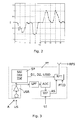
- Fig. 2 illustrates an example of such time history of Doppler shift based data indicating a velocity component along an axis between US transmitter and portable tag PT. It shows a portable tag PT which first moves away from the US transmitter (1-9 seconds) and then approaches it again (11-18 seconds). By integrating the velocity [m/s] plotted versus time [second] in the graph of Fig. 2 , a corresponding measure of distance between US transmitter and portable tag PT can be estimated, thereby providing data related to the position within the zone.
- the processor P preferably has a user interface allowing users to access location data, either using a graphic output providing an overview of all zones or a selection of some of all zones, and/or by means of receiving a user input in the form of a request for location of a specific person or object, to which the processor may respond either with a text output and/or audible output.
- the processor may, in larger systems, be connected to a network such as an internal computer network of a company, so as to allow users of the network to access zone location information, either for tracking persons or objects.
- FIG. 3 illustrates components of a preferred portable tag PT.
- a US receiver USR includes a microphone and pre-amplifier arranged to receive US and as well as audio frequency sound A, thereby utilizing one microphone and pre-amplifier for US location purpose and audio contact with a user wearing the portable tag PT.
- the electric output from the US receiver USR is applied to a signal processor system SP that converts the electric signal to a digital representation and measures a sequence of a received US signal. Based on the received US sequence, the signal processor system SP then calculates a signal strength indicator SSI, a Doppler shift indicator DSI, and extracts an identification code IDE according to a predetermined US transmitter ID code represented in the US signal.
- the SSI and DSI can be calculated by algorithms such as explained above.
- the SSI, DSI, and IDE are then applied to a Radio Frequency transmitter RFT as respective first data value D1, second data value D2, and US transmitter identification USID.
- the ID for the portable tag itself PTID is also applied to the Radio Frequency transmitter RFT, and it transmit a Radio Frequency signal RFS with these data represented therein.
- the portable tag PT is arranged to receive a user input UI by a user interface, e.g. in the form of an alert button placed on an accessible part of the portable tag casing.
- the user interface UIF allows an electric audio signal AS to be applied to the Radio Frequency transmitter RFT and included in the transmitted Radio Frequency signal RFS, e.g. together with an alarm code that allows a receiver to take appropriate action.
- the user's voice is transmitted in the Radio Frequency signal RFS, thus allowing the user to give a message e.g. to a central receiver.
- the electric output from the US receiver USR is low-pass filtered by low-pass filter LPF, e.g. with a cut off frequency of such as 5 kHz or 10 kHz.
- the low-pass filtered signal may then be analog-to-digital converted by converter ADC, and via the user interface UIF, the electric audio signal AS is then applied to the Radio Frequency transmitter RFT.
- the components illustrated in Fig. 3 are meant to illustrate preferred functions of the portable tag PT rather than practical implementations, since practical circuit design for the portable tag PT can be chosen as known by the skilled person.
- Fig. 4 illustrates signal timing for an embodiment with a portable tag which only has an RF transmitter.
- the US transmitter transmits US signals with intermediate pauses.
- the tag listens, and wants to initiate a location procedure, it transmits its identification code in an RF signal.
- the US signal from the US transmitter may include a code identifying itself, as described.
- the tag may include the US transmitter identification code, thereby allowing the processor to determine the location of the tag. Since the tag initiates the location procedure, the tag may be in a power saving mode with the US receiver turned off, unless it wants to initiate a location, such "waking up" being caused possibly such as also described above.
- Fig. 5 illustrates the variant where the tag further has an RF receiver.
- the US transmitter broadcasts US signals, such as in Fig. 4 .
- An external RF transmitter sends an RF signal requesting the specific tag to "wake up", and in response to this "wake up" RF signal, the tag can activates its US receiver, in case it is not always active, and the tag then receives the subsequent broadcast US signal and replies with transmitting an RF signal with its identification code, and possibly also with a code identifying the US transmitter.
- US 7,283,423 describes a method for reducing effects of line noise at ultrasound frequencies which may disturb US communication in a US based zone location system.
- Switch-mode power supplies have become common, and they often operate in the range 20-60 kHz, generating an almost sinusoidal ultrasonic noise, with fluorescent lamps and computer monitors being significant noise source in this respect.
- An alternative solution which can be used when the PT has an RF receiver is that the US stations also has a US receiver which constantly monitors and scans the US band. When there are no tags transmitting, the US station will characterize the background noise including lines. As part of the communications to the tag, the US station will select and inform the tag which US centre frequency it uses, thus ensuring that the tag listens in an interference-free part of the band.
- US receivers can be implemented using a preamplifier, A/D-conversion and an FFT-processor as in underwater frequency shift keying (FSK) communications systems, such as outlined e.g. in Fig. 4 in [ Wax, D., "MFSK--The Basis for Robust Acoustical Communications," OCEANS , vol.13, no., pp. 61-66, Sep 1981 ], and Fig. 4 in [ Scussel, K.F.; Rice, J.A.; Merriam, S., "A new MFSK acoustic modem for operation in adverse underwater channels," OCEANS '97. MTS/IEEE Conference Proceedings, vol.1, pp.247-254, 6-9 Oct 1997 ].
- FSK underwater frequency shift keying
- PLL phase-locked loop
- the invention provides a zone location system with ultrasound US transmitters S1, S2, S3 located in respective zones Z1, Z2, Z3 such as rooms of a building B.
- the US transmitters transmit a US signal US with a unique ID code USID represented therein.
- the portable tag PT includes an ultrasound receiver USR arranged to receive the US signal. Based on the received US signal, the portable tag PT measures a strength of the received US signal. The portable tag also measures a parameter related to a movement of the portable tag PT, a Doppler shift based on the received US signal. Further, the portable tag PT extracts the USID.
- a processor P connected to a Radio Frequency receiver RFR receives the data from the portable tag PT and determines a connection between PTID and the zone Z2 in which it is present based on the USID. Further, the processor utilizes data D1 and D2 to calculate an estimated position POS within the zone Z2. Especially, estimated distance between US transmitter S2 and portable tag PT and velocity of the portable tag are estimated based on D1 and D2, thus assisting in estimating the position POS of the portable tag PT.
- the system may further be combined with a Radio Frequency based positioning system, e.g.
Landscapes
- Engineering & Computer Science (AREA)
- Physics & Mathematics (AREA)
- General Physics & Mathematics (AREA)
- Radar, Positioning & Navigation (AREA)
- Remote Sensing (AREA)
- Computer Networks & Wireless Communication (AREA)
- Measurement Of Velocity Or Position Using Acoustic Or Ultrasonic Waves (AREA)
- Mobile Radio Communication Systems (AREA)
- Position Fixing By Use Of Radio Waves (AREA)
- Surgical Instruments (AREA)
- Investigating Or Analyzing Materials By The Use Of Ultrasonic Waves (AREA)
Claims (15)
- Zonenlokalisierungssystem, angeordnet zur Bestimmung, in welcher Zone eines vorbestimmten Satzes Zonen (Z1, Z2, Z3), wie Räumen, sich ein portables Tag (PT) befindet, wobei das System umfasst- einen Satz Ultraschallsender (S1, S2, S3), die sich in den jeweiligen Zonen des vorbestimmten Satzes Zonen (Z1, Z2, Z3) befinden, wobei die Ultraschallsender (S1, S2, S3) zum Erzeugen eines Ultraschallsignals (US), wie eines Ultraschallburstsignals, angeordnet ist,- ein portables Tag (PT) mit einem damit verbundenen Identifizierungscode (PTID), wobei das portable Tag (PT) umfasst- einen Ultraschallempfänger (USR), angeordnet zum Empfang des Ultraschallsignals (US),- Signalverarbeitungsmittel (SP), angeordnet zum- Messen einer Stärke des empfangenen Ultraschallsignals (US) und zum Erzeugen eines ersten Datenwerts (D1) auf der Grundlage dieser Stärke und- Messen eines Dopplereffektparameters auf der Grundlage des empfangenen Ultraschallsignals (US) und zum Erzeugen eines zweiten Datenwerts (D2) auf der Grundlage des Dopplereffektparameters und- einen Radiofrequenzsender (RFT), angeordnet zum Senden eines Radiofrequenzsignals (RFS) mit den Identifizierungscode (PTID) darstellenden Daten, dem ersten und dem zweiten Datenwert (D1, D2),- eine Radiofrequenzstation (RS), angeordnet zum Empfangen des Radiofrequenzsignals (RFS) von dem portablen Tag (PT) und- einen Prozessor (P), der wirksam mit der Radiofrequenzstation (RS) verbunden ist, wobei der Prozessor (P) angeordnet ist zum- Identifizieren des portablen Tags (PT) auf der Grundlage des Identifizierungscodes (PTID),- Bestimmen, in welcher Zone (Z2) sich das portable Tag (PT) befindet, und zwar auf der Grundlage der Erfassung, welcher Ultraschallsender (S1, S2, S3) des Satzes auf dem Ultraschallkanal eine Verbindung mit dem portablen Tag (PT) herstellen kann, und- Bestimmen einer Position (POS) in der Zone auf der Grundlage des ersten Datenwerts (D1) und Daten, die mit der Position in Zusammenhang stehen und durch Integration einer Geschwindigkeit auf der Grundlage des zweiten Datenwerts (D2) bereitgestellt werden.
- Zonenlokalisierungssystem nach Anspruch 1, wobei der Prozessor (P) zur Bestimmung eines Abstands zwischen dem Ultraschallsender (S1, S2, S3) und dem portablen Tag (PT) auf der Grundlage des ersten Datenwerts (D1) und demgemäß zur Bestimmung der Position (POS) innerhalb der Zone (Z2) angeordnet ist.
- Zonenlokalisierungssystem nach einem der vorhergehenden Ansprüche, wobei das von einem der Ultraschallsender (S1, S2, S3) gesendete Ultraschallsignal (US) einen Code (USID) zur Identifizierung des Ultraschallsenders (S1, S2, S3) umfasst.
- Zonenlokalisierungssystem nach Anspruch 3, wobei das portable Tag (PT) mit dem Ultraschallsignal (US) empfangene Daten in dem Radiofrequenzsignal (RFS) sendet.
- Zonenlokalisierungssystem nach Anspruch 4, wobei das portable Tag (PT) den Code (USID) zur Identifizierung des Ultraschallsenders (S1, S2, S3) in dem Radiofrequenzsignal (RFS) sendet und wobei der Prozessor (P) auf der Grundlage des Codes (USID) zur Identifizierung des Ultraschallsenders (S1, S2, S3), der in dem Radiofrequenzsignal (RFS) empfangen wurde, bestimmt, in welcher Zone (Z2) sich das portable Tag (PT) befindet.
- Zonenlokalisierungssystem nach einem der vorhergehenden Ansprüche, wobei das portable Tag (PT) einen Radiofrequenzempfänger umfasst, der zum Empfang eines Radiofrequenzsignals von einem externen Radiofrequenzsender angeordnet ist.
- Zonenlokalisierungssystem nach Anspruch 6, wobei das portable Tag (PT) zum Empfang einer Lokalisierungsanforderungen in dem Radiofrequenzsignal von dem externen Radiofrequenzsender angeordnet ist.
- Zonenlokalisierungssystem nach Anspruch 7, wobei das portable Tag (PT) zum Aktivieren des Ultraschallempfängers (USR) als Reaktion auf die Anforderung angeordnet ist.
- Zonenlokalisierungssystem nach einem der vorhergehenden Ansprüche, wobei der Radiofrequenzempfänger (RFR) und die Ultraschallsender (S1, S2, S3) stationären Bauteile sind und wobei der Prozessor (P) über eine drahtlose Radiofrequenzverbindung wirksam mit dem Radiofrequenzempfänger verbunden ist.
- Zonenlokalisierungssystem nach einem der vorhergehenden Ansprüche, umfassend eine Mehrzahl von portablen Tags (PT) jeweils mit einem damit verbundenen eindeutigen Identifizierungscode (PTID).
- Zonenlokalisierungssystem nach einem der vorhergehenden Ansprüche, wobei der vorbestimmte Satz Zonen (Z1, Z2, Z3) den Räumen eines Gebäudes (B) entspricht.
- Zonenlokalisierungssystem nach einem der vorhergehenden Ansprüche, wobei sich mindestens erste und zweite räumlich getrennte Ultraschallsender in mindestens einem der vorbestimmten Sätze Zonen (Z1, Z2, Z3) befinden und wobei das portable Tag (PT) zum Empfang eines ersten Ultraschallsignals von dem ersten Ultraschallsender und eines zweiten Ultraschallsignals von dem zweiten Ultraschallsender angeordnet ist.
- Verwendung eines Systems nach einem der Ansprüche 1-12 zum Lokalisieren von Personen.
- Verwendung eines Systems nach einem der Ansprüche 1-12 zum Lokalisieren von Gegenständen.
- Verfahren zur Bestimmung, in welcher Zone eines vorbestimmten Satzes Zonen (Z1, Z2, Z3) sich ein portables Tag (PT) befindet, wobei das Verfahren umfasst- Senden eines Ultraschallsignals an einen Ultraschallkanal von einem Satz Ultraschallsender (S1, S2, S3), von denen sich mindestens einer in jedem des vorbestimmten Satzes Zonen (Z1, Z2, Z3) befindet- Empfangen des Ultraschallsignals (US) in dem portablen Tag (PT)- Bestimmen einer Stärke des empfangenen Ultraschallsignals (US) und Erzeugen eines ersten Datenwerts (D1) auf der Grundlage dieser Stärke,- Bestimmen eines Dopplereffektparameters auf der Grundlage des empfangenen Ultraschallsignals (US) und Erzeugen eines zweiten Datenwerts (D2) auf der Grundlage des Dopplereffektparameters,- Senden eines Radiofrequenzsignals (RFS) einschließlich eines Codes (PTID) zur Identifizierung des portablen Tags und dem ersten und dem zweiten Datenwert (D1, D2) von dem portablen Tag,- Empfangen des Radiofrequenzsignals (RFS) von dem portablen Tag (PT),- Identifizieren des portablen Tags (PT) auf der Grundlage des Identifizierungscodes (PTID),- Bestimmen, in welcher Zone (Z2) sich das portable Tag (PT) befindet, und zwar durch Erfassen, welcher Ultraschallsender (S1, S2, S3) des Satzes auf dem Ultraschallkanal eine Verbindung mit dem portablen Tag (PT) herstellen kann, und- Bestimmen einer Position (POS) in der Zone auf der Grundlage des ersten Datenwerts (D1) und Daten, die mit der Position in Zusammenhang stehen und durch Integration einer Geschwindigkeit auf der Grundlage des zweiten Datenwerts (D2) bereitgestellt werden.
Priority Applications (4)
| Application Number | Priority Date | Filing Date | Title |
|---|---|---|---|
| EP08159582A EP2065726B9 (de) | 2007-11-13 | 2008-07-03 | Ultraschallzonenauffindungssystem mit hoher Kapazität |
| PL08159582T PL2065726T3 (pl) | 2007-11-13 | 2008-07-03 | Ultradźwiękowy system lokalizacji stref o wysokiej przepustowości |
| PCT/EP2008/065386 WO2009062956A2 (en) | 2007-11-13 | 2008-11-12 | Ultrasound zone location system with high capacity |
| US12/742,619 US8779895B2 (en) | 2007-11-13 | 2008-11-12 | Ultrasound zone location system with high capacity |
Applications Claiming Priority (2)
| Application Number | Priority Date | Filing Date | Title |
|---|---|---|---|
| EP07120535 | 2007-11-13 | ||
| EP08159582A EP2065726B9 (de) | 2007-11-13 | 2008-07-03 | Ultraschallzonenauffindungssystem mit hoher Kapazität |
Publications (4)
| Publication Number | Publication Date |
|---|---|
| EP2065726A2 EP2065726A2 (de) | 2009-06-03 |
| EP2065726A3 EP2065726A3 (de) | 2009-06-17 |
| EP2065726B1 EP2065726B1 (de) | 2012-02-01 |
| EP2065726B9 true EP2065726B9 (de) | 2012-04-25 |
Family
ID=39221465
Family Applications (1)
| Application Number | Title | Priority Date | Filing Date |
|---|---|---|---|
| EP08159582A Active EP2065726B9 (de) | 2007-11-13 | 2008-07-03 | Ultraschallzonenauffindungssystem mit hoher Kapazität |
Country Status (7)
| Country | Link |
|---|---|
| US (1) | US8779895B2 (de) |
| EP (1) | EP2065726B9 (de) |
| AT (1) | ATE544082T1 (de) |
| DK (1) | DK2065726T3 (de) |
| ES (1) | ES2385956T3 (de) |
| PL (1) | PL2065726T3 (de) |
| WO (1) | WO2009062956A2 (de) |
Families Citing this family (32)
| Publication number | Priority date | Publication date | Assignee | Title |
|---|---|---|---|---|
| US8164439B2 (en) * | 2009-06-18 | 2012-04-24 | The General Hospital Corp. | Ultrasonic compliance zone system |
| US9264151B1 (en) * | 2009-07-29 | 2016-02-16 | Shopkick, Inc. | Method and system for presence detection |
| US10304069B2 (en) | 2009-07-29 | 2019-05-28 | Shopkick, Inc. | Method and system for presentment and redemption of personalized discounts |
| CN102985840B (zh) * | 2010-03-23 | 2015-07-29 | 奥斯陆大学 | 具有高精度的稳固超声室内定位系统 |
| US8174931B2 (en) | 2010-10-08 | 2012-05-08 | HJ Laboratories, LLC | Apparatus and method for providing indoor location, position, or tracking of a mobile computer using building information |
| EP2469298B1 (de) | 2010-12-23 | 2015-02-18 | Televic Healthcare NV | Verfahren und Vorrichtung zur Bestimmung der Position eines Ziels |
| CN102890765B (zh) * | 2011-07-20 | 2015-10-14 | 富士通株式会社 | 射频识别标签定位方法和装置 |
| US20130093962A1 (en) * | 2011-10-14 | 2013-04-18 | Echostar Technologies L.L.C. | Systems and methods for pairing a remote control to video or audio components using ultrasound signals |
| US9244150B2 (en) * | 2012-05-29 | 2016-01-26 | Nokia Technologies Oy | Method and apparatus for providing location information of user devices based on signal frequencies of transmitters |
| WO2014089040A1 (en) * | 2012-12-03 | 2014-06-12 | University Of Florida Research Foundation, Inc. | Apparatus, method, and software systems for smartphone-based fine-grained indoor localization |
| DE102013205547B4 (de) * | 2013-03-28 | 2018-01-11 | Siemens Aktiengesellschaft | Verfahren zur Ortsbestimmung eines mobilen Gerätes innerhalb eines Gebäudes sowie Vorrichtungen zur Durchführung desselben |
| US9140777B2 (en) * | 2013-05-14 | 2015-09-22 | Symbol Technologies, Llc | Ultrasonic locationing using enrollment mode |
| CN103413110B (zh) * | 2013-08-29 | 2016-06-01 | 戴生伟 | 一种物品定位搜索装置、组件及方法 |
| US20150117153A1 (en) * | 2013-10-25 | 2015-04-30 | Symbol Technologies, Inc. | Adaptive transmitter cluster area for ultrasonic locationing system |
| JP6160447B2 (ja) * | 2013-10-31 | 2017-07-12 | ヤマハ株式会社 | 端末装置及びプログラム |
| US9995824B2 (en) * | 2014-04-09 | 2018-06-12 | Thomas Danaher Harvey | Methods and system to assist search for lost and submerged objects |
| US10871566B2 (en) * | 2014-04-09 | 2020-12-22 | Thomas Danaher Harvey | Methods and system to assist search and interception of lost objects |
| US10816638B2 (en) | 2014-09-16 | 2020-10-27 | Symbol Technologies, Llc | Ultrasonic locationing interleaved with alternate audio functions |
| US10609475B2 (en) | 2014-12-05 | 2020-03-31 | Stages Llc | Active noise control and customized audio system |
| WO2016123746A1 (en) * | 2015-02-03 | 2016-08-11 | SZ DJI Technology Co., Ltd. | System and method for detecting aerial vehicle position and velocity via sound |
| US10051412B2 (en) * | 2015-02-25 | 2018-08-14 | Ricoh Company, Ltd. | Locational information transmission system, locational information transmission apparatus, and information processing device |
| CN108370494B (zh) * | 2015-12-04 | 2022-05-17 | 德克萨斯大学系统董事会 | 精确跟踪移动设备以有效地通过移动设备来控制其他设备 |
| US9791540B2 (en) | 2015-12-14 | 2017-10-17 | Google Inc. | Self-organizing hybrid indoor location system |
| US20180003817A1 (en) * | 2016-06-30 | 2018-01-04 | Intel Corporation | Ultrasonic location system |
| US20180088205A1 (en) * | 2016-09-29 | 2018-03-29 | Nokia Technologies Oy | Positioning |
| US10945080B2 (en) | 2016-11-18 | 2021-03-09 | Stages Llc | Audio analysis and processing system |
| US9980075B1 (en) | 2016-11-18 | 2018-05-22 | Stages Llc | Audio source spatialization relative to orientation sensor and output |
| US9980042B1 (en) | 2016-11-18 | 2018-05-22 | Stages Llc | Beamformer direction of arrival and orientation analysis system |
| DE102017205271A1 (de) * | 2017-03-29 | 2018-10-04 | Robert Bosch Gmbh | Verfahren und System zur Lokalisierung eines mobilen Geräts und mobiles Gerät |
| DE102017205278A1 (de) * | 2017-03-29 | 2018-10-04 | Robert Bosch Gmbh | Verfahren zur Lokalisierung und Lokalisierungssystem mit einer Vorrichtung eingerichtet zur Lokalisierung |
| GB2561216A (en) * | 2017-04-05 | 2018-10-10 | Flowscape Ab | Signal strength positioning |
| EP3591431B1 (de) * | 2018-07-02 | 2021-05-05 | NXP USA, Inc. | Kommunikationseinheit und verfahren zur taktverteilung und synchronisation |
Family Cites Families (70)
| Publication number | Priority date | Publication date | Assignee | Title |
|---|---|---|---|---|
| JPS62128358A (ja) * | 1985-11-29 | 1987-06-10 | Toshiba Corp | 入場者管理システム |
| US5051741A (en) * | 1990-03-28 | 1991-09-24 | Wesby Philip B | Locating system |
| US5119104A (en) * | 1990-05-04 | 1992-06-02 | Heller Alan C | Location system adapted for use in multipath environments |
| US5268734A (en) * | 1990-05-31 | 1993-12-07 | Parkervision, Inc. | Remote tracking system for moving picture cameras and method |
| US5528232A (en) * | 1990-06-15 | 1996-06-18 | Savi Technology, Inc. | Method and apparatus for locating items |
| US5529073A (en) * | 1992-05-21 | 1996-06-25 | Hewlett-Packard Company | Method and apparatus for recording physiologic signals |
| US5495427A (en) * | 1992-07-10 | 1996-02-27 | Northrop Grumman Corporation | High speed high resolution ultrasonic position and orientation tracker using a single ultrasonic frequency |
| US5872516A (en) * | 1994-02-22 | 1999-02-16 | Bonge, Jr.; Nicholas J. | Ultrasonic transceiver and remote controlled devices for pets |
| DE4409167C1 (de) * | 1994-03-17 | 1995-06-29 | Siemens Ag | Schlüssellose Zugangskontrolleinrichtung |
| IL111550A (en) | 1994-11-07 | 1998-04-05 | Visonic Ltd | Signaling network system |
| US5873040A (en) * | 1996-08-13 | 1999-02-16 | International Business Machines Corporation | Wireless 911 emergency location |
| US5920287A (en) * | 1997-01-21 | 1999-07-06 | Widata Corporation | Radio location system for precisely tracking objects by RF transceiver tags which randomly and repetitively emit wideband identification signals |
| GB2332053B (en) * | 1997-12-04 | 2002-01-09 | Olivetti Res Ltd | Detection system for determinning positional and other information about objects |
| US6553013B1 (en) * | 1997-04-12 | 2003-04-22 | At&T Laboratories, Cambridge Limited | Detection system for determining positional information about objects |
| GB2332052B (en) * | 1997-12-04 | 2002-01-16 | Olivetti Res Ltd | Detection system for determining orientation information about objects |
| GB2324632B (en) * | 1997-10-20 | 1999-08-11 | Steven Derek Pike | Microphone unit |
| IL122079A (en) * | 1997-10-30 | 2002-02-10 | Netmor Ltd | Ultrasound system for positioning and tracking |
| US7010369B2 (en) * | 1997-11-07 | 2006-03-07 | Hill-Rom Services, Inc. | Medical equipment controller |
| AU2475299A (en) * | 1998-01-30 | 1999-08-16 | Widata Corporation | Radio location system including transceiver tags |
| GB9901300D0 (en) * | 1999-01-22 | 1999-03-10 | Olivetti Research Ltd | A method of increasing the capacity and addressing rate of an Ultrasonic location system |
| US7575550B1 (en) * | 1999-03-11 | 2009-08-18 | Biosense, Inc. | Position sensing based on ultrasound emission |
| US7549960B2 (en) * | 1999-03-11 | 2009-06-23 | Biosense, Inc. | Implantable and insertable passive tags |
| US6456239B1 (en) * | 1999-08-25 | 2002-09-24 | Rf Technologies, Inc. | Method and apparatus for locating mobile tags |
| US6196973B1 (en) * | 1999-09-30 | 2001-03-06 | Siemens Medical Systems, Inc. | Flow estimation using an ultrasonically modulated contrast agent |
| US7037270B2 (en) * | 2000-03-02 | 2006-05-02 | Mayo Foundation For Medical Education And Research | Small ultrasound transducers |
| US20020014951A1 (en) * | 2000-05-05 | 2002-02-07 | Kramer Kenneth L. | Remote control for a hospital bed |
| JP2002055154A (ja) * | 2000-08-10 | 2002-02-20 | Mitsubishi Heavy Ind Ltd | 水槽内遊泳体とその制御装置及び位置計測装置 |
| US8482399B2 (en) * | 2000-09-08 | 2013-07-09 | Intelligent Technologies International, Inc. | Asset monitoring using the internet |
| US7911324B2 (en) * | 2001-02-16 | 2011-03-22 | Automotive Technologies International, Inc. | Method and system for obtaining information about RFID-equipped objects |
| EP1350153B1 (de) * | 2000-12-15 | 2012-07-11 | Polycom, Inc. | System und verfahren zur unterscheidung der gemeinsamen anordnung von einrichtungen |
| US6995654B2 (en) * | 2000-12-15 | 2006-02-07 | X-Cyte, Inc. | Apparatus and method for locating a tagged item |
| AU2002255695A1 (en) * | 2001-03-09 | 2002-09-24 | Radianse, Inc. | A system and method for performing object association using a location tracking system |
| JP3828758B2 (ja) * | 2001-03-15 | 2006-10-04 | ジーイー・メディカル・システムズ・グローバル・テクノロジー・カンパニー・エルエルシー | 信号処理回路および超音波ドップラ装置 |
| DE10113545A1 (de) | 2001-03-20 | 2002-10-02 | Tenovis Gmbh & Co Kg | System und Verfahren zur Positionsbestimmung |
| US7242306B2 (en) * | 2001-05-08 | 2007-07-10 | Hill-Rom Services, Inc. | Article locating and tracking apparatus and method |
| US6970097B2 (en) | 2001-05-10 | 2005-11-29 | Ge Medical Systems Information Technologies, Inc. | Location system using retransmission of identifying information |
| US6535120B1 (en) * | 2001-09-25 | 2003-03-18 | John Sebanc, Dds | Programmable universal locating system |
| WO2003027981A1 (en) * | 2001-09-27 | 2003-04-03 | Xydis Thomas G | Monitoring method and system |
| US6720876B1 (en) * | 2002-02-14 | 2004-04-13 | Interval Research Corporation | Untethered position tracking system |
| NO315917B1 (no) * | 2002-04-09 | 2003-11-10 | Filetrac As | System og fremgangsmåte for posisjonsbestemmelse av objekter |
| US8035508B2 (en) * | 2002-06-11 | 2011-10-11 | Intelligent Technologies International, Inc. | Monitoring using cellular phones |
| US8581688B2 (en) * | 2002-06-11 | 2013-11-12 | Intelligent Technologies International, Inc. | Coastal monitoring techniques |
| US20080108372A1 (en) * | 2002-06-11 | 2008-05-08 | Intelligent Technologies International, Inc. | Inductively Powered Asset Monitoring System |
| NO329096B1 (no) * | 2002-12-04 | 2010-08-23 | Sonitor Technologies As | Ultralyd sporings- og lokaliseringssystem |
| NO318010B1 (no) | 2002-12-04 | 2005-01-17 | Sonitor Technologies As | Ultralyd lokaliseringssystem |
| CH715792B1 (de) * | 2002-12-06 | 2020-07-31 | Ruag Electronics | Vorrichtung und Verfahren zur Positionsbestimmung. |
| US7785259B2 (en) * | 2003-10-03 | 2010-08-31 | Mayo Foundation For Medical Education And Research | Detection of motion in vibro-acoustography |
| CN1981310A (zh) | 2003-10-20 | 2007-06-13 | 雷第安斯公司 | 用于联系第一信号和第二信号的定位系统 |
| EP1719086B1 (de) * | 2004-01-27 | 2013-03-27 | Richard Harry Turner | Verfahren und vorrichtung zur detektion und verfolgung von objekten in einem definierten bereich |
| US7982601B2 (en) * | 2004-03-22 | 2011-07-19 | Innovation Law Group, Ltd. | Multi-modal active RFID tag with biometric sensors, systems and methods of ITV tracking |
| US7152791B2 (en) * | 2004-03-30 | 2006-12-26 | Honeywell International, Inc. | Identifying the location of an asset |
| US7362258B2 (en) * | 2004-03-31 | 2008-04-22 | Honda Motor Co., Ltd. | Transponder detection system using radio and light wave signals |
| EP1869728B1 (de) * | 2005-03-14 | 2014-02-26 | The Alfred E Mann Foundation for Scientific Research | System und verfahren zum finden von objekten und zum kommunizieren mit ihnen |
| CN1841084B (zh) * | 2005-03-29 | 2011-12-07 | 松下电器产业株式会社 | 混合测距方法 |
| US7333018B2 (en) * | 2005-07-25 | 2008-02-19 | Honeywell International Inc. | Asset location system with enhanced accuracy |
| US9285471B2 (en) * | 2005-11-21 | 2016-03-15 | Hewlett-Packard Development Company, L.P. | Method and apparatus for localization of RFID tags |
| EP1976433B1 (de) * | 2006-01-07 | 2011-03-09 | Arthur Koblasz | Verwendung von rfid zur verhinderung oder erkennung von stürzen, umhergehen, bettausstieg sowie medizinischen fehlern |
| WO2007110626A2 (en) | 2006-03-28 | 2007-10-04 | In2Games Limited | Wireless position sensing in three dimensions using ultrasound |
| US20090315735A1 (en) * | 2006-04-10 | 2009-12-24 | Bhavani Neeraj S | Patient flow management and analysis using location tracking |
| US20080033752A1 (en) * | 2006-08-04 | 2008-02-07 | Valence Broadband, Inc. | Methods and systems for monitoring staff/patient contacts and ratios |
| US20080180213A1 (en) * | 2006-11-07 | 2008-07-31 | Flax Stephen W | Digital Intercom Based Data Management System |
| ITRM20060638A1 (it) * | 2006-11-30 | 2008-06-01 | Cardinale Ciccotti Giuseppe | Metodo per la localizzazione di dispositivi remoti utilizzante onde acustiche ed elettromagnetiche |
| US8054160B2 (en) * | 2007-03-09 | 2011-11-08 | Innovation Law Group, Ltd. | RFID tag power conservation system and method |
| KR100939640B1 (ko) * | 2007-12-17 | 2010-01-28 | 한국전자통신연구원 | 다중 주파수의 음원을 이용한 위치인식방법 및위치인식시스템 |
| PT2245606E (pt) * | 2008-02-14 | 2015-03-31 | Lojack Corp | Sistema de recuperação de bens |
| US8212653B1 (en) * | 2008-03-20 | 2012-07-03 | The General Hospital Corp. | Protected zone system |
| US20090273465A1 (en) * | 2008-05-02 | 2009-11-05 | Adi Shamir | Room separation in a wlan based rtls and method therefor |
| CN101592727B (zh) * | 2008-05-29 | 2013-05-01 | 日电(中国)有限公司 | 自治超声波室内定位系统、装置和方法 |
| CN101726738B (zh) * | 2008-10-30 | 2012-12-26 | 日电(中国)有限公司 | 多目标定位系统以及基于功率控制的多路访问控制方法 |
| US8164439B2 (en) * | 2009-06-18 | 2012-04-24 | The General Hospital Corp. | Ultrasonic compliance zone system |
-
2008
- 2008-07-03 DK DK08159582.9T patent/DK2065726T3/da active
- 2008-07-03 ES ES08159582T patent/ES2385956T3/es active Active
- 2008-07-03 EP EP08159582A patent/EP2065726B9/de active Active
- 2008-07-03 PL PL08159582T patent/PL2065726T3/pl unknown
- 2008-07-03 AT AT08159582T patent/ATE544082T1/de active
- 2008-11-12 US US12/742,619 patent/US8779895B2/en active Active
- 2008-11-12 WO PCT/EP2008/065386 patent/WO2009062956A2/en active Application Filing
Also Published As
| Publication number | Publication date |
|---|---|
| WO2009062956A2 (en) | 2009-05-22 |
| US8779895B2 (en) | 2014-07-15 |
| PL2065726T3 (pl) | 2012-07-31 |
| ATE544082T1 (de) | 2012-02-15 |
| US20110018687A1 (en) | 2011-01-27 |
| WO2009062956A3 (en) | 2009-07-23 |
| DK2065726T3 (da) | 2012-05-21 |
| EP2065726B1 (de) | 2012-02-01 |
| EP2065726A3 (de) | 2009-06-17 |
| EP2065726A2 (de) | 2009-06-03 |
| ES2385956T3 (es) | 2012-08-06 |
Similar Documents
| Publication | Publication Date | Title |
|---|---|---|
| EP2065726B1 (de) | Ultraschallzonenauffindungssystem mit hoher Kapazität | |
| CA2542600C (en) | Location system | |
| US8416071B2 (en) | Relative location determination of mobile sensor nodes | |
| US7822424B2 (en) | Method and system for rangefinding using RFID and virtual triangulation | |
| USRE43740E1 (en) | Reverse locator | |
| Oberholzer et al. | Spiderbat: Augmenting wireless sensor networks with distance and angle information | |
| EP3639052B1 (de) | Übertragungsvorrichtung zur verwendung bei standortbestimmungssystemen | |
| US7567794B2 (en) | Peak picking in location systems | |
| WO2004051304A1 (en) | Ultrasonic tracking and locating system | |
| NO315917B1 (no) | System og fremgangsmåte for posisjonsbestemmelse av objekter | |
| EP2979109B1 (de) | Messung eines reflektierten ultraschallsignals zur taktsteuerung eines ultraschallemitters | |
| EP1706758B1 (de) | Kombinierte radar- und kommunikationsverbindung | |
| WO2017078181A2 (en) | Method for registering location of device and device | |
| WO2013132393A1 (en) | System and method for indoor positioning using sound masking signals | |
| Hammoud et al. | Robust ultrasound-based room-level localization system using COTS components | |
| JP2010041254A (ja) | Wlanベースのrtlsにおける改良された部屋の区別およびその方法 | |
| Murakami et al. | Smartphone localization using active-passive acoustic sensing | |
| CN115469272A (zh) | 一种用户设备自动定位方法和系统 | |
| WO2008070341A2 (en) | Two-stage location system | |
| KR100553191B1 (ko) | 초음파를 이용한 위치인식 시스템 및 방법 | |
| CN110869793B (zh) | 确定音频设备的位置/定向 | |
| KR20120072191A (ko) | 위치를 추적하는 방법 및 위치 추적 장치 | |
| Ens et al. | Low-power simplex ultrasound communication for indoor localization | |
| WO2013108229A2 (en) | Robust presence detection through audible components analysis | |
| WO2024107057A1 (en) | Device ranging |
Legal Events
| Date | Code | Title | Description |
|---|---|---|---|
| PUAI | Public reference made under article 153(3) epc to a published international application that has entered the european phase |
Free format text: ORIGINAL CODE: 0009012 |
|
| PUAL | Search report despatched |
Free format text: ORIGINAL CODE: 0009013 |
|
| AK | Designated contracting states |
Kind code of ref document: A2 Designated state(s): AT BE BG CH CY CZ DE DK EE ES FI FR GB GR HR HU IE IS IT LI LT LU LV MC MT NL NO PL PT RO SE SI SK TR |
|
| AX | Request for extension of the european patent |
Extension state: AL BA MK RS |
|
| AK | Designated contracting states |
Kind code of ref document: A3 Designated state(s): AT BE BG CH CY CZ DE DK EE ES FI FR GB GR HR HU IE IS IT LI LT LU LV MC MT NL NO PL PT RO SE SI SK TR |
|
| AX | Request for extension of the european patent |
Extension state: AL BA MK RS |
|
| 17P | Request for examination filed |
Effective date: 20091215 |
|
| 17Q | First examination report despatched |
Effective date: 20100112 |
|
| AKX | Designation fees paid |
Designated state(s): AT BE BG CH CY CZ DE DK EE ES FI FR GB GR HR HU IE IS IT LI LT LU LV MC MT NL NO PL PT RO SE SI SK TR |
|
| GRAP | Despatch of communication of intention to grant a patent |
Free format text: ORIGINAL CODE: EPIDOSNIGR1 |
|
| GRAS | Grant fee paid |
Free format text: ORIGINAL CODE: EPIDOSNIGR3 |
|
| GRAA | (expected) grant |
Free format text: ORIGINAL CODE: 0009210 |
|
| RAP1 | Party data changed (applicant data changed or rights of an application transferred) |
Owner name: UNIVERSITETET I OSLO |
|
| AK | Designated contracting states |
Kind code of ref document: B1 Designated state(s): AT BE BG CH CY CZ DE DK EE ES FI FR GB GR HR HU IE IS IT LI LT LU LV MC MT NL NO PL PT RO SE SI SK TR |
|
| REG | Reference to a national code |
Ref country code: GB Ref legal event code: FG4D |
|
| REG | Reference to a national code |
Ref country code: AT Ref legal event code: REF Ref document number: 544082 Country of ref document: AT Kind code of ref document: T Effective date: 20120215 Ref country code: CH Ref legal event code: EP |
|
| REG | Reference to a national code |
Ref country code: DE Ref legal event code: R096 Ref document number: 602008013026 Country of ref document: DE Effective date: 20120405 |
|
| REG | Reference to a national code |
Ref country code: CH Ref legal event code: NV Representative=s name: MEYER & KOLLEGEN |
|
| REG | Reference to a national code |
Ref country code: NL Ref legal event code: T3 |
|
| REG | Reference to a national code |
Ref country code: DK Ref legal event code: T3 |
|
| REG | Reference to a national code |
Ref country code: SE Ref legal event code: TRGR |
|
| LTIE | Lt: invalidation of european patent or patent extension |
Effective date: 20120201 |
|
| PG25 | Lapsed in a contracting state [announced via postgrant information from national office to epo] |
Ref country code: IS Free format text: LAPSE BECAUSE OF FAILURE TO SUBMIT A TRANSLATION OF THE DESCRIPTION OR TO PAY THE FEE WITHIN THE PRESCRIBED TIME-LIMIT Effective date: 20120601 Ref country code: NO Free format text: LAPSE BECAUSE OF FAILURE TO SUBMIT A TRANSLATION OF THE DESCRIPTION OR TO PAY THE FEE WITHIN THE PRESCRIBED TIME-LIMIT Effective date: 20120501 Ref country code: HR Free format text: LAPSE BECAUSE OF FAILURE TO SUBMIT A TRANSLATION OF THE DESCRIPTION OR TO PAY THE FEE WITHIN THE PRESCRIBED TIME-LIMIT Effective date: 20120201 Ref country code: LT Free format text: LAPSE BECAUSE OF FAILURE TO SUBMIT A TRANSLATION OF THE DESCRIPTION OR TO PAY THE FEE WITHIN THE PRESCRIBED TIME-LIMIT Effective date: 20120201 |
|
| REG | Reference to a national code |
Ref country code: PL Ref legal event code: T3 |
|
| REG | Reference to a national code |
Ref country code: ES Ref legal event code: FG2A Ref document number: 2385956 Country of ref document: ES Kind code of ref document: T3 Effective date: 20120806 |
|
| PG25 | Lapsed in a contracting state [announced via postgrant information from national office to epo] |
Ref country code: PT Free format text: LAPSE BECAUSE OF FAILURE TO SUBMIT A TRANSLATION OF THE DESCRIPTION OR TO PAY THE FEE WITHIN THE PRESCRIBED TIME-LIMIT Effective date: 20120601 Ref country code: LV Free format text: LAPSE BECAUSE OF FAILURE TO SUBMIT A TRANSLATION OF THE DESCRIPTION OR TO PAY THE FEE WITHIN THE PRESCRIBED TIME-LIMIT Effective date: 20120201 Ref country code: GR Free format text: LAPSE BECAUSE OF FAILURE TO SUBMIT A TRANSLATION OF THE DESCRIPTION OR TO PAY THE FEE WITHIN THE PRESCRIBED TIME-LIMIT Effective date: 20120502 Ref country code: FI Free format text: LAPSE BECAUSE OF FAILURE TO SUBMIT A TRANSLATION OF THE DESCRIPTION OR TO PAY THE FEE WITHIN THE PRESCRIBED TIME-LIMIT Effective date: 20120201 Ref country code: BE Free format text: LAPSE BECAUSE OF FAILURE TO SUBMIT A TRANSLATION OF THE DESCRIPTION OR TO PAY THE FEE WITHIN THE PRESCRIBED TIME-LIMIT Effective date: 20120201 |
|
| PG25 | Lapsed in a contracting state [announced via postgrant information from national office to epo] |
Ref country code: CY Free format text: LAPSE BECAUSE OF FAILURE TO SUBMIT A TRANSLATION OF THE DESCRIPTION OR TO PAY THE FEE WITHIN THE PRESCRIBED TIME-LIMIT Effective date: 20120201 |
|
| PG25 | Lapsed in a contracting state [announced via postgrant information from national office to epo] |
Ref country code: EE Free format text: LAPSE BECAUSE OF FAILURE TO SUBMIT A TRANSLATION OF THE DESCRIPTION OR TO PAY THE FEE WITHIN THE PRESCRIBED TIME-LIMIT Effective date: 20120201 Ref country code: RO Free format text: LAPSE BECAUSE OF FAILURE TO SUBMIT A TRANSLATION OF THE DESCRIPTION OR TO PAY THE FEE WITHIN THE PRESCRIBED TIME-LIMIT Effective date: 20120201 Ref country code: SI Free format text: LAPSE BECAUSE OF FAILURE TO SUBMIT A TRANSLATION OF THE DESCRIPTION OR TO PAY THE FEE WITHIN THE PRESCRIBED TIME-LIMIT Effective date: 20120201 Ref country code: CZ Free format text: LAPSE BECAUSE OF FAILURE TO SUBMIT A TRANSLATION OF THE DESCRIPTION OR TO PAY THE FEE WITHIN THE PRESCRIBED TIME-LIMIT Effective date: 20120201 |
|
| REG | Reference to a national code |
Ref country code: AT Ref legal event code: MK05 Ref document number: 544082 Country of ref document: AT Kind code of ref document: T Effective date: 20120201 |
|
| PG25 | Lapsed in a contracting state [announced via postgrant information from national office to epo] |
Ref country code: SK Free format text: LAPSE BECAUSE OF FAILURE TO SUBMIT A TRANSLATION OF THE DESCRIPTION OR TO PAY THE FEE WITHIN THE PRESCRIBED TIME-LIMIT Effective date: 20120201 |
|
| PLBE | No opposition filed within time limit |
Free format text: ORIGINAL CODE: 0009261 |
|
| STAA | Information on the status of an ep patent application or granted ep patent |
Free format text: STATUS: NO OPPOSITION FILED WITHIN TIME LIMIT |
|
| 26N | No opposition filed |
Effective date: 20121105 |
|
| PG25 | Lapsed in a contracting state [announced via postgrant information from national office to epo] |
Ref country code: AT Free format text: LAPSE BECAUSE OF FAILURE TO SUBMIT A TRANSLATION OF THE DESCRIPTION OR TO PAY THE FEE WITHIN THE PRESCRIBED TIME-LIMIT Effective date: 20120201 |
|
| PG25 | Lapsed in a contracting state [announced via postgrant information from national office to epo] |
Ref country code: MC Free format text: LAPSE BECAUSE OF NON-PAYMENT OF DUE FEES Effective date: 20120731 |
|
| REG | Reference to a national code |
Ref country code: DE Ref legal event code: R097 Ref document number: 602008013026 Country of ref document: DE Effective date: 20121105 |
|
| REG | Reference to a national code |
Ref country code: IE Ref legal event code: MM4A |
|
| PG25 | Lapsed in a contracting state [announced via postgrant information from national office to epo] |
Ref country code: IE Free format text: LAPSE BECAUSE OF NON-PAYMENT OF DUE FEES Effective date: 20120703 Ref country code: BG Free format text: LAPSE BECAUSE OF FAILURE TO SUBMIT A TRANSLATION OF THE DESCRIPTION OR TO PAY THE FEE WITHIN THE PRESCRIBED TIME-LIMIT Effective date: 20120501 Ref country code: MT Free format text: LAPSE BECAUSE OF FAILURE TO SUBMIT A TRANSLATION OF THE DESCRIPTION OR TO PAY THE FEE WITHIN THE PRESCRIBED TIME-LIMIT Effective date: 20120201 |
|
| PG25 | Lapsed in a contracting state [announced via postgrant information from national office to epo] |
Ref country code: LU Free format text: LAPSE BECAUSE OF NON-PAYMENT OF DUE FEES Effective date: 20120703 |
|
| PG25 | Lapsed in a contracting state [announced via postgrant information from national office to epo] |
Ref country code: HU Free format text: LAPSE BECAUSE OF FAILURE TO SUBMIT A TRANSLATION OF THE DESCRIPTION OR TO PAY THE FEE WITHIN THE PRESCRIBED TIME-LIMIT Effective date: 20080703 |
|
| REG | Reference to a national code |
Ref country code: FR Ref legal event code: PLFP Year of fee payment: 9 |
|
| REG | Reference to a national code |
Ref country code: FR Ref legal event code: PLFP Year of fee payment: 10 |
|
| REG | Reference to a national code |
Ref country code: FR Ref legal event code: PLFP Year of fee payment: 11 |
|
| REG | Reference to a national code |
Ref country code: DE Ref legal event code: R082 Ref document number: 602008013026 Country of ref document: DE |
|
| PGFP | Annual fee paid to national office [announced via postgrant information from national office to epo] |
Ref country code: TR Payment date: 20220624 Year of fee payment: 15 Ref country code: PL Payment date: 20220629 Year of fee payment: 15 |
|
| PGFP | Annual fee paid to national office [announced via postgrant information from national office to epo] |
Ref country code: NL Payment date: 20220722 Year of fee payment: 15 |
|
| PGFP | Annual fee paid to national office [announced via postgrant information from national office to epo] |
Ref country code: SE Payment date: 20220722 Year of fee payment: 15 Ref country code: IT Payment date: 20220726 Year of fee payment: 15 Ref country code: GB Payment date: 20220721 Year of fee payment: 15 Ref country code: ES Payment date: 20220805 Year of fee payment: 15 Ref country code: DK Payment date: 20220725 Year of fee payment: 15 Ref country code: DE Payment date: 20220725 Year of fee payment: 15 |
|
| PGFP | Annual fee paid to national office [announced via postgrant information from national office to epo] |
Ref country code: FR Payment date: 20220722 Year of fee payment: 15 |
|
| PGFP | Annual fee paid to national office [announced via postgrant information from national office to epo] |
Ref country code: CH Payment date: 20220725 Year of fee payment: 15 |
|
| REG | Reference to a national code |
Ref country code: DE Ref legal event code: R119 Ref document number: 602008013026 Country of ref document: DE |
|
| REG | Reference to a national code |
Ref country code: DK Ref legal event code: EBP Effective date: 20230731 |
|
| REG | Reference to a national code |
Ref country code: CH Ref legal event code: PL |
|
| REG | Reference to a national code |
Ref country code: SE Ref legal event code: EUG |
|
| REG | Reference to a national code |
Ref country code: NL Ref legal event code: MM Effective date: 20230801 |
|
| GBPC | Gb: european patent ceased through non-payment of renewal fee |
Effective date: 20230703 |
|
| PG25 | Lapsed in a contracting state [announced via postgrant information from national office to epo] |
Ref country code: NL Free format text: LAPSE BECAUSE OF NON-PAYMENT OF DUE FEES Effective date: 20230801 |
|
| PG25 | Lapsed in a contracting state [announced via postgrant information from national office to epo] |
Ref country code: NL Free format text: LAPSE BECAUSE OF NON-PAYMENT OF DUE FEES Effective date: 20230801 Ref country code: DE Free format text: LAPSE BECAUSE OF NON-PAYMENT OF DUE FEES Effective date: 20240201 Ref country code: CH Free format text: LAPSE BECAUSE OF NON-PAYMENT OF DUE FEES Effective date: 20230731 Ref country code: GB Free format text: LAPSE BECAUSE OF NON-PAYMENT OF DUE FEES Effective date: 20230703 |