EP2065601A2 - Spreizdübel - Google Patents
Spreizdübel Download PDFInfo
- Publication number
- EP2065601A2 EP2065601A2 EP08170292A EP08170292A EP2065601A2 EP 2065601 A2 EP2065601 A2 EP 2065601A2 EP 08170292 A EP08170292 A EP 08170292A EP 08170292 A EP08170292 A EP 08170292A EP 2065601 A2 EP2065601 A2 EP 2065601A2
- Authority
- EP
- European Patent Office
- Prior art keywords
- anchoring
- expansion
- expansion anchor
- anchor according
- end portion
- Prior art date
- Legal status (The legal status is an assumption and is not a legal conclusion. Google has not performed a legal analysis and makes no representation as to the accuracy of the status listed.)
- Granted
Links
Images


Classifications
-
- F—MECHANICAL ENGINEERING; LIGHTING; HEATING; WEAPONS; BLASTING
- F16—ENGINEERING ELEMENTS AND UNITS; GENERAL MEASURES FOR PRODUCING AND MAINTAINING EFFECTIVE FUNCTIONING OF MACHINES OR INSTALLATIONS; THERMAL INSULATION IN GENERAL
- F16B—DEVICES FOR FASTENING OR SECURING CONSTRUCTIONAL ELEMENTS OR MACHINE PARTS TOGETHER, e.g. NAILS, BOLTS, CIRCLIPS, CLAMPS, CLIPS OR WEDGES; JOINTS OR JOINTING
- F16B13/00—Dowels or other devices fastened in walls or the like by inserting them in holes made therein for that purpose
- F16B13/04—Dowels or other devices fastened in walls or the like by inserting them in holes made therein for that purpose with parts gripping in the hole or behind the reverse side of the wall after inserting from the front
- F16B13/06—Dowels or other devices fastened in walls or the like by inserting them in holes made therein for that purpose with parts gripping in the hole or behind the reverse side of the wall after inserting from the front combined with expanding sleeve
- F16B13/063—Dowels or other devices fastened in walls or the like by inserting them in holes made therein for that purpose with parts gripping in the hole or behind the reverse side of the wall after inserting from the front combined with expanding sleeve by the use of an expander
- F16B13/066—Dowels or other devices fastened in walls or the like by inserting them in holes made therein for that purpose with parts gripping in the hole or behind the reverse side of the wall after inserting from the front combined with expanding sleeve by the use of an expander fastened by extracting a separate expander-part, actuated by the screw, nail or the like
Definitions
- the present innovation relates to an expansion anchor.
- the present innovation relates to an screw anchor adapted to be used for fastening or anchoring onto walls or articles, to which explicit reference will be made in the following description without therefore loosing in generality.
- Screw anchors comprising a tubular element having a deformable end portion in which longitudinal slits or cuts are obtained, which divide the end portion itself, at the zones concerned by the cuts, into a series of longitudinal anchoring fins; a cone-shaped expansion nut or body engaged onto the end of the end portion; and a screw, which is accommodated inside the tubular element and is adapted to be screwed onto the expansion nut or cone so as to be able to progressively displace it into the end portion of the anchor, so as to cause the radial deformation of the longitudinal fins which, by spreading outwards, determine the anchoring of the anchor to the wall.
- a screw anchor is provided as claimed in claim 1 and preferably, but not necessarily, in anyone of the claims which either directly or indirectly depend on claim 1.
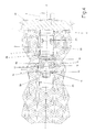
- numeral 1 indicates as a whole an screw anchor, which is adapted to be engaged into a hole 25 obtained in a wall 26, or in any body or anchoring element, with the longitudinal axis A thereof coaxial to the axis of the hole 25 itself, and is capable of coupling with a fastening screw 2 of known type which, when actuated, is adapted to cause a deformation of the screw anchor 1 inside the hole 25 so as to determine the anchoring to the wall 26.
- the screw anchor 1 essentially consists of a tubular element 3 preferably, but not necessarily, made of metal or plastic material, or of any other similar material, on which the following parts may be identified: a central truck 4; preferably, but not necessarily, a collar 5, and a deformable end portion 6, connected at the opposite ends of the central trunk 4, respectively.
- the screw anchor 1 further comprises an expansion nut or body 9, which is engaged onto the end portion 6 of the screw anchor 1, on the part opposite to the collar 5, and is adapted to be screwed onto the threaded part of the shank 2a of the screw 2 to be axially displaced inside the end portion 6 of the screw 2 itself, so as to cause the outward radial deformation of the anchoring fins 8.
- each anchoring fin 8 has an essentially rectangular shape and at its end facing the expansion body 9, displays a ridge 10 defining the external side edge of the anchoring fin 8 and having an essentially triangular cross section.
- each anchoring fin 8 further presents two protruding side teeth 11 having a pointed shape, each of which is coplanar with the anchoring fin 8 and extends towards the protruding tooth 11 of an adjacent anchoring fin 8, so as to delimit, with the latter, the end of the longitudinal slot 7 present between the two facing side edges of the anchoring fins 8 themselves.
- each protruding side tooth 11 has an essentially triangular shape and extends from the body of the anchoring fin 8 so as to be arranged, with its pointed portion, at least partially in abutment with the pointed portion of the protruding side tooth 11 of the adjacent anchoring fin 8.
- the expansion nut or body 8 is preferably, but not necessarily, made of metal or plastic material, or of other similar material, is shaped so as to be essentially cone-shaped, and comprises a threaded through hole 14 which extends coaxially to the axis A and is adapted to accommodate the threaded shank 2a of the screw 2.
- the expansion nut or body 8 displays a portion 15 having an essentially square shape, in which the vertexes of the square define anti-rotation protrusions 16 each of which is engaged inside a corresponding longitudinal slot 7 and is adapted to prevent the expansion nut or body 9 from rotating about the longitudinal axis A.
- the smaller base of the conical portion of the expansion nut or body 9 is essentially inscribed in the square defining the portion 15, while the vertexes of the portion 15 which define the protrusions 16 of the expansion nut or body 9 are essentially pyramid-shaped so as to be inserted and displaced into the corresponding longitudinal slots 7 when screwing the screw 2 onto the expansion nut or body 9.
- Each anchoring fin 8 of the anchor 1 further displays an external surface 8a comprising a plurality of annular notches 18, which are arranged coaxially to the axis A, and essentially equally spaced from each other so as to advantageously increase the degree of friction and grip of the anchoring fins 8 on the internal wall of the hole 25 which accommodates the screw anchor 1.
- each anchoring fin 8 of the anchor 1 has an external knurled or milled surface 8a so as to increase the degree of friction and grip of the anchoring fins 8 on the internal wall of the hole which accommodates the screw anchor 1.
- a segment of the central trunk 4 also displays an external surface 4a having a plurality of annular notches or cavities 4b which are coaxial to the longitudinal axis A and essentially equally spaced from each other along the longitudinal axis A itself.
- the segment of the central trunk 4 of the anchor 1 comprises an external knurled or milled surface 8a so as to increase the degree of friction of the screw anchor 1 on the internal wall of the hole 25.
- Anti-rotation ridges 20 are further present on the central trunk 4 of the screw anchor 1, which are arranged in pairs on two reciprocally orthogonal planes laying on the longitudinal axis A, and which overhangingly extend outwards from the central truck 4.
- screwing the screw 2 on the expansion nut or body 9 causes the displacement of the expansion body 9 itself inside the end portion 6, which by radially pushing the anchoring fins 8 outwards determines the expansion of the end portion 6 itself into the hole 25 of the wall 26.
- each anchoring fin 8 is brought in abutment with the internal wall of the hole 25, while the protruding teeth 11 of the anchoring fin 8 are partially driven into the internal wall of the hole 25 itself, thus creating a pawl anchoring system which then counters the axial displacement of the screw anchor 1 in the direction for extracting the screw anchor 1 from the hole 25.
- the external surface 8a of the anchoring fins 8 is brought in contact with the internal wall of the hole, thus generating, in virtue of the notches or cavities 18 thereof, a friction force which counters the axial displacement of the screw anchor 1 in the direction for extracting the anchor from the hole 25.
- the above-described screw anchor 1 has the advantage of ensuring a particularly high degree of anchoring; indeed, the combined action of the anchoring performed by the protruding side teeth and the friction obtained by the notches of the external surface of the anchoring fins 8 ensures an excellent fixing of the anchor to the wall.
Landscapes
- Engineering & Computer Science (AREA)
- General Engineering & Computer Science (AREA)
- Mechanical Engineering (AREA)
- Dowels (AREA)
- Joining Of Building Structures In Genera (AREA)
- Piles And Underground Anchors (AREA)
Applications Claiming Priority (1)
| Application Number | Priority Date | Filing Date | Title |
|---|---|---|---|
| IT000146U ITTO20070146U1 (it) | 2007-11-29 | 2007-11-29 | Tassello ad espansione |
Publications (4)
| Publication Number | Publication Date |
|---|---|
| EP2065601A2 true EP2065601A2 (de) | 2009-06-03 |
| EP2065601A8 EP2065601A8 (de) | 2009-10-21 |
| EP2065601A3 EP2065601A3 (de) | 2010-12-29 |
| EP2065601B1 EP2065601B1 (de) | 2013-08-14 |
Family
ID=40315291
Family Applications (1)
| Application Number | Title | Priority Date | Filing Date |
|---|---|---|---|
| EP08170292.0A Not-in-force EP2065601B1 (de) | 2007-11-29 | 2008-11-28 | Spreizdübel |
Country Status (4)
| Country | Link |
|---|---|
| US (1) | US8287217B2 (de) |
| EP (1) | EP2065601B1 (de) |
| CA (1) | CA2645433A1 (de) |
| IT (1) | ITTO20070146U1 (de) |
Cited By (3)
| Publication number | Priority date | Publication date | Assignee | Title |
|---|---|---|---|---|
| CN103727109A (zh) * | 2012-10-16 | 2014-04-16 | 程长青 | 一种装拆自由的膨胀螺丝 |
| CN106351926A (zh) * | 2016-09-19 | 2017-01-25 | 浙江亦宸五金有限公司 | 一种防转动的膨胀螺栓 |
| CN110159330A (zh) * | 2019-06-28 | 2019-08-23 | 张亚歌 | 一种张拉锁紧锚杆 |
Families Citing this family (10)
| Publication number | Priority date | Publication date | Assignee | Title |
|---|---|---|---|---|
| DE102008001055A1 (de) * | 2008-04-08 | 2009-10-15 | Hilti Aktiengesellschaft | Spreizdübel |
| ES2325526B1 (es) * | 2009-02-17 | 2010-06-08 | Pablo Jose Adriaensens Aparicio | Dispositivo para la fijacion al suelo de estructuras metalicas. |
| US20120311947A1 (en) * | 2011-06-07 | 2012-12-13 | John Van Wissen | Expansion anchor |
| US8720156B2 (en) * | 2012-09-14 | 2014-05-13 | Charles Porter | Wall panel attachment system |
| US9765529B2 (en) | 2015-09-11 | 2017-09-19 | Charles Porter | Panel fastener |
| EP3536985A1 (de) * | 2018-03-05 | 2019-09-11 | HILTI Aktiengesellschaft | Spreizanker mit unterschiedlichen expansionswinkeln |
| WO2019218090A1 (en) * | 2018-05-18 | 2019-11-21 | Robert Cousineau | Self-undercut expansion anchor system with improved cutters |
| EP3805485B1 (de) * | 2019-10-09 | 2025-04-23 | DOKA GmbH | Anker |
| EP4306733A4 (de) * | 2021-04-30 | 2024-10-30 | A&S System Co,. Ltd. | Ankerbolzen |
| FR3153114B1 (fr) * | 2023-09-20 | 2025-09-26 | Airbus Operations Sas | Dispositif de liaison comprenant un manchon expansible et un écrou conique, assemblage comprenant au moins un tel dispositif de liaison |
Family Cites Families (14)
| Publication number | Priority date | Publication date | Assignee | Title |
|---|---|---|---|---|
| US612316A (en) * | 1898-10-11 | James f | ||
| US1164322A (en) * | 1914-09-23 | 1915-12-14 | Walter C Yeatman | Expansion-bolt. |
| DK135813C (da) * | 1967-04-05 | 1977-11-21 | Mortensen L | Ekspansionsbolt |
| ZA772338B (en) | 1976-04-29 | 1978-03-29 | Itt | Bolt anchor |
| US4516885A (en) * | 1980-11-21 | 1985-05-14 | Jennmar Corporation | Method and apparatus for combining resin bonding and mechanical anchoring of a bolt in a rock formation |
| US4613264A (en) * | 1982-04-16 | 1986-09-23 | Mcintyre Douglas O | Anchor bolt |
| US4481702A (en) | 1982-09-30 | 1984-11-13 | The Boeing Company | Method of assembling threaded insert bushing within a working material |
| DE3420375C2 (de) * | 1984-06-01 | 1987-03-19 | Fischer, Artur, Dr.H.C., 7244 Waldachtal | Dübel |
| DE3637658A1 (de) * | 1986-11-05 | 1988-05-19 | Hilti Ag | Spreizduebel mit zwei unterschiedlichen spreizkonen |
| DE3731818A1 (de) * | 1987-09-22 | 1989-03-30 | Hilti Ag | Spreizduebel |
| GB9210235D0 (en) * | 1992-05-13 | 1992-07-01 | Emhart Inc | Anchor bolt |
| AT403402B (de) * | 1995-11-06 | 1998-02-25 | Mark Rudolf | Befestigungselement |
| US5702216A (en) | 1996-08-27 | 1997-12-30 | Wu; Ming-Hsin | Expanding wall plug |
| DE10035580B4 (de) | 2000-07-21 | 2013-07-25 | Simpson Strong-Tie Ireland Limited | Formschlüssig setzbarer Hinterschneid-Anker |
-
2007
- 2007-11-29 IT IT000146U patent/ITTO20070146U1/it unknown
-
2008
- 2008-11-26 US US12/323,936 patent/US8287217B2/en not_active Expired - Fee Related
- 2008-11-27 CA CA002645433A patent/CA2645433A1/en not_active Abandoned
- 2008-11-28 EP EP08170292.0A patent/EP2065601B1/de not_active Not-in-force
Cited By (3)
| Publication number | Priority date | Publication date | Assignee | Title |
|---|---|---|---|---|
| CN103727109A (zh) * | 2012-10-16 | 2014-04-16 | 程长青 | 一种装拆自由的膨胀螺丝 |
| CN106351926A (zh) * | 2016-09-19 | 2017-01-25 | 浙江亦宸五金有限公司 | 一种防转动的膨胀螺栓 |
| CN110159330A (zh) * | 2019-06-28 | 2019-08-23 | 张亚歌 | 一种张拉锁紧锚杆 |
Also Published As
| Publication number | Publication date |
|---|---|
| US8287217B2 (en) | 2012-10-16 |
| US20090142156A1 (en) | 2009-06-04 |
| ITTO20070146U1 (it) | 2009-05-30 |
| EP2065601A8 (de) | 2009-10-21 |
| CA2645433A1 (en) | 2009-05-29 |
| EP2065601A3 (de) | 2010-12-29 |
| EP2065601B1 (de) | 2013-08-14 |
Similar Documents
| Publication | Publication Date | Title |
|---|---|---|
| EP2065601A2 (de) | Spreizdübel | |
| EP2119920B1 (de) | Spreizdübel | |
| US4861206A (en) | Straddling plug | |
| CA2585161C (en) | Self-drilling hollow wall anchor | |
| EP2734740B1 (de) | Schraubenkopf | |
| JPH0511368Y2 (de) | ||
| EP1467107B1 (de) | Schraubenanker | |
| JPS60182903A (ja) | ねじスタッド用プラスチックファスナ | |
| US3437004A (en) | Sheet metal expandable fastener | |
| US2396501A (en) | Wall plug | |
| JPH01314560A (ja) | 医学的な使用のための拡張栓 | |
| US3136350A (en) | Plastic screw anchor | |
| KR101404938B1 (ko) | 펀칭작업이 필요없는 개선된 세트 앵커볼트 | |
| US3894469A (en) | Fastener | |
| JP2015102166A (ja) | 固定具および固定構造 | |
| JP2010043728A (ja) | スクリュグロメット | |
| EP1243801A1 (de) | Spreizanker | |
| US20070160418A1 (en) | Quick assembly bolt jacket | |
| JP5696834B2 (ja) | 共回り防止機能付拡張アンカー | |
| CA2958396C (en) | Masonry anchor of the expansion type | |
| US3779495A (en) | Wall anchor for electrical conduits | |
| EP2428689A1 (de) | Schlaganker und Befestigungsadapter dafür | |
| US1639231A (en) | Bolt anchor | |
| KR200266066Y1 (ko) | 기초볼트 | |
| JP2024106362A (ja) | 固定具 |
Legal Events
| Date | Code | Title | Description |
|---|---|---|---|
| PUAI | Public reference made under article 153(3) epc to a published international application that has entered the european phase |
Free format text: ORIGINAL CODE: 0009012 |
|
| AK | Designated contracting states |
Kind code of ref document: A2 Designated state(s): AT BE BG CH CY CZ DE DK EE ES FI FR GB GR HR HU IE IS IT LI LT LU LV MC MT NL NO PL PT RO SE SI SK TR |
|
| AX | Request for extension of the european patent |
Extension state: AL BA MK RS |
|
| PUAL | Search report despatched |
Free format text: ORIGINAL CODE: 0009013 |
|
| AK | Designated contracting states |
Kind code of ref document: A3 Designated state(s): AT BE BG CH CY CZ DE DK EE ES FI FR GB GR HR HU IE IS IT LI LT LU LV MC MT NL NO PL PT RO SE SI SK TR |
|
| AX | Request for extension of the european patent |
Extension state: AL BA MK RS |
|
| 17P | Request for examination filed |
Effective date: 20110629 |
|
| AKX | Designation fees paid |
Designated state(s): DE FR GB |
|
| GRAP | Despatch of communication of intention to grant a patent |
Free format text: ORIGINAL CODE: EPIDOSNIGR1 |
|
| GRAS | Grant fee paid |
Free format text: ORIGINAL CODE: EPIDOSNIGR3 |
|
| GRAA | (expected) grant |
Free format text: ORIGINAL CODE: 0009210 |
|
| AK | Designated contracting states |
Kind code of ref document: B1 Designated state(s): DE FR GB |
|
| REG | Reference to a national code |
Ref country code: GB Ref legal event code: FG4D |
|
| REG | Reference to a national code |
Ref country code: DE Ref legal event code: R096 Ref document number: 602008026721 Country of ref document: DE Effective date: 20131010 |
|
| PGFP | Annual fee paid to national office [announced via postgrant information from national office to epo] |
Ref country code: FR Payment date: 20131118 Year of fee payment: 6 |
|
| PLBE | No opposition filed within time limit |
Free format text: ORIGINAL CODE: 0009261 |
|
| STAA | Information on the status of an ep patent application or granted ep patent |
Free format text: STATUS: NO OPPOSITION FILED WITHIN TIME LIMIT |
|
| 26N | No opposition filed |
Effective date: 20140515 |
|
| GBPC | Gb: european patent ceased through non-payment of renewal fee |
Effective date: 20131128 |
|
| REG | Reference to a national code |
Ref country code: DE Ref legal event code: R119 Ref document number: 602008026721 Country of ref document: DE Effective date: 20140603 Ref country code: DE Ref legal event code: R097 Ref document number: 602008026721 Country of ref document: DE Effective date: 20140515 |
|
| PG25 | Lapsed in a contracting state [announced via postgrant information from national office to epo] |
Ref country code: DE Free format text: LAPSE BECAUSE OF NON-PAYMENT OF DUE FEES Effective date: 20140603 |
|
| PG25 | Lapsed in a contracting state [announced via postgrant information from national office to epo] |
Ref country code: GB Free format text: LAPSE BECAUSE OF NON-PAYMENT OF DUE FEES Effective date: 20131128 |
|
| REG | Reference to a national code |
Ref country code: FR Ref legal event code: ST Effective date: 20150731 |
|
| PG25 | Lapsed in a contracting state [announced via postgrant information from national office to epo] |
Ref country code: FR Free format text: LAPSE BECAUSE OF NON-PAYMENT OF DUE FEES Effective date: 20141201 |