EP2065546A2 - Hinge fitting for pivotable mounting of the frame of a shutter - Google Patents
Hinge fitting for pivotable mounting of the frame of a shutter Download PDFInfo
- Publication number
- EP2065546A2 EP2065546A2 EP08020799A EP08020799A EP2065546A2 EP 2065546 A2 EP2065546 A2 EP 2065546A2 EP 08020799 A EP08020799 A EP 08020799A EP 08020799 A EP08020799 A EP 08020799A EP 2065546 A2 EP2065546 A2 EP 2065546A2
- Authority
- EP
- European Patent Office
- Prior art keywords
- frame
- hinge fitting
- fitting according
- guide plate
- guide
- Prior art date
- Legal status (The legal status is an assumption and is not a legal conclusion. Google has not performed a legal analysis and makes no representation as to the accuracy of the status listed.)
- Granted
Links
- XAGFODPZIPBFFR-UHFFFAOYSA-N aluminium Chemical compound [Al] XAGFODPZIPBFFR-UHFFFAOYSA-N 0.000 claims abstract description 5
- 229910052782 aluminium Inorganic materials 0.000 claims abstract description 5
- 238000010276 construction Methods 0.000 description 2
- 230000000295 complement effect Effects 0.000 description 1
- 230000001419 dependent effect Effects 0.000 description 1
Images


Classifications
-
- E—FIXED CONSTRUCTIONS
- E05—LOCKS; KEYS; WINDOW OR DOOR FITTINGS; SAFES
- E05D—HINGES OR SUSPENSION DEVICES FOR DOORS, WINDOWS OR WINGS
- E05D5/00—Construction of single parts, e.g. the parts for attachment
- E05D5/02—Parts for attachment, e.g. flaps
- E05D5/0215—Parts for attachment, e.g. flaps for attachment to profile members or the like
- E05D5/0223—Parts for attachment, e.g. flaps for attachment to profile members or the like with parts, e.g. screws, extending through the profile wall or engaging profile grooves
- E05D5/0238—Parts for attachment, e.g. flaps for attachment to profile members or the like with parts, e.g. screws, extending through the profile wall or engaging profile grooves with parts engaging profile grooves
-
- E—FIXED CONSTRUCTIONS
- E05—LOCKS; KEYS; WINDOW OR DOOR FITTINGS; SAFES
- E05D—HINGES OR SUSPENSION DEVICES FOR DOORS, WINDOWS OR WINGS
- E05D5/00—Construction of single parts, e.g. the parts for attachment
- E05D5/02—Parts for attachment, e.g. flaps
- E05D5/04—Flat flaps
-
- E—FIXED CONSTRUCTIONS
- E05—LOCKS; KEYS; WINDOW OR DOOR FITTINGS; SAFES
- E05D—HINGES OR SUSPENSION DEVICES FOR DOORS, WINDOWS OR WINGS
- E05D7/00—Hinges or pivots of special construction
- E05D7/04—Hinges adjustable relative to the wing or the frame
-
- E—FIXED CONSTRUCTIONS
- E05—LOCKS; KEYS; WINDOW OR DOOR FITTINGS; SAFES
- E05Y—INDEXING SCHEME RELATING TO HINGES OR OTHER SUSPENSION DEVICES FOR DOORS, WINDOWS OR WINGS AND DEVICES FOR MOVING WINGS INTO OPEN OR CLOSED POSITION, CHECKS FOR WINGS AND WING FITTINGS NOT OTHERWISE PROVIDED FOR, CONCERNED WITH THE FUNCTIONING OF THE WING
- E05Y2900/00—Application of doors, windows, wings or fittings thereof
- E05Y2900/10—Application of doors, windows, wings or fittings thereof for buildings or parts thereof
- E05Y2900/13—Application of doors, windows, wings or fittings thereof for buildings or parts thereof characterised by the type of wing
- E05Y2900/146—Shutters
Landscapes
- Engineering & Computer Science (AREA)
- Mechanical Engineering (AREA)
- Hinges (AREA)
Abstract
Description
Die Erfindung betrifft einen Scharnierbeschlag zur schwenkbaren Befestigung eines Rahmens, insbesondere des Rahmens eines Fensterladens, der über vier rechtwinklig miteinander verbundene Rahmenabschnitte mit wenigstens einer eine Gehrung aufweisenden Eckverbindung verfügt, an einem Gegenbeschlag, mit wenigstens einer ein mit dem Gegenbeschlag verbindbares Anschlußelement aufweisenden Führungsplatte, die zwischen einer Frontseite eines der Rahmenabschnitte und einer Abdeckplatte einklemmbar ist, welche entlang dem Rahmenabschnitt verschiebbar und durch Formschluß an der Frontseite des Rahmenabschnittes befestigbar ist, wobei die Abdeckplatte mit einem Befestigungselement verbindbar ist, das aus einem Dorn und einer diesen aufnehmenden Basis gebildet ist. Die Erfindung betrifft außerdem bevorzugte Verwendungen eines solchen Scharnierbeschlags.The invention relates to a hinge fitting for pivotally mounting a frame, in particular the frame of a shutter, which has four rectangularly interconnected frame sections with at least one mitered corner connection, at a counter fitting, with at least one connectable with the counter fitting connection element guide plate, the between a front side of the frame portions and a cover plate is clamped, which is fastened along the frame portion and by positive engagement on the front side of the frame portion, wherein the cover plate is connectable to a fastening element, which is formed from a mandrel and a receiving base. The invention also relates to preferred uses of such a hinge fitting.
Aus der
Durch die
Nachteilig an diesem Scharnierbeschlag ist eine eher aufwendige Konstruktion mit dem zusätzlichen Erfordernis eines Brückenelements.By the
A disadvantage of this hinge fitting is a rather expensive construction with the additional requirement of a bridge element.
Die
Zur Fixierung dieses Teils des Befestigungselementes in der gewünschten Position an dem Rahmenabschnitt weist dieser Teil des Befestigungselementes einen rechten Winkel auf, wobei einer der Schenkel auf die Frontplatte des Rahmenabschnittes ragt und mit einem Dorn versehen ist. Dieser Dom dient dazu, in eine Aussparung eines weiteren Teils des Befestigungselementes in Form einer Abdeckplatte einzugreifen. Dazwischen ist eine Führungsplatte vorgesehen, an welche eine Hülse angeformt ist, die mit einem Kloben zusammenwirkt, um eine schwenkbare Befestigung des Fensterladens zu gestatten.
Auch bei diesem vorgeschlagenen Scharnierbeschlag ist eine eher aufwendige Konstruktion als nachteilig zu nennen.The
For fixing this part of the fastening element in the desired position on the frame portion, this part of the fastening element at a right angle, wherein one of the legs protrudes onto the front plate of the frame portion and is provided with a mandrel. This dome serves to engage in a recess of another part of the fastening element in the form of a cover plate. In between, a guide plate is provided, to which a sleeve is formed which cooperates with a clamp to allow a pivotable attachment of the shutter.
Also in this proposed hinge fitting is a rather expensive construction to call disadvantageous.
Ausgehend von diesem Stand der Technik liegt der Erfindung die Aufgabe zugrunde, einen Scharnierbeschlag der eingangs genannten Art zu schaffen, der in weniger aufwendiger Weise entlang einem Rahmenabschnitt an einer beliebigen Stelle, und insbesondere im Bereich der Gehrung zwischen zwei Rahmenabschnitten befestigbar ist.Based on this prior art, the present invention seeks to provide a hinge fitting of the type mentioned, which can be fastened in a less expensive manner along a frame portion at any point, and in particular in the miter between two frame sections.
Diese Aufgabe wird erfindungsgemäß durch einen Scharnierbeschlag gelöst, der zur schwenkbaren Befestigung eines Rahmens, insbesondere des Rahmens eines Fensterladens an einem Gegenbeschlag dient, wobei der Rahmen über vier rechtwinklig miteinander verbundene Rahmenabschnitte mit wenigstens einer eine Gehrung aufweisenden Eckverbindung verfügt, und mit wenigstens einer ein mit dem Gegenbeschlag verbindbares Anschlußelement aufweisenden Führungsplatte, die zwischen einer Frontseite eines der Rahmenabschnitte und einer Abdeckplatte einklemmbar ist, welche entlang dem Rahmenabschnitt verschiebbar und durch Formschluß an der Frontseite des Rahmenabschnittes befestigbar ist, wobei die Abdeckplatte mit einem Befestigungselement verbindbar ist, das aus einem Dom und einer diesen aufnehmenden Basis gebildet ist. Die Basis des Befestigungselements verläuft dabei insgesamt innerhalb einer entlang der Frontseite des Rahmenabschnittes ausgebildeten Führung, welche die Basis vollständig aufnimmt, wobei die Führung über ihre gesamte Länge eine Öffnung aufweist, die den Dom aufnimmt und aus welcher dieser nach außen ragt, so daß das Befestigungselement entlang der Frontseite des Rahmenabschnittes bis zu der an dessen Ende angeordneten Gehrung führbar und feststellbar ist.This object is achieved by a hinge fitting, which serves for the pivotable attachment of a frame, in particular the frame of a shutter on a counter fitting, wherein the frame has four rectangular interconnected frame sections with at least one miter having corner joint, and at least one with the counter fitting connectable connecting element having guide plate which can be clamped between a front side of the frame sections and a cover plate which is fastened along the frame portion and displaceable by positive engagement on the front side of the frame portion, wherein the cover plate is connectable to a fastener consisting of a dome and a receiving base is formed. The base of the fastener extends overall within a formed along the front side of the frame portion guide which completely receives the base, wherein the guide over its entire length has an opening which receives the dome and from which this protrudes outwards, so that the fastener along the front side of the frame portion to the arranged at the end miter is feasible and lockable.
Dadurch wird es möglich, den Rahmenabschnitt z. B. bei einem Fensterladen über seine gesamte Länge für das Anbringen des Scharnierbeschlags nutzbar zu machen, ohne konstruktiv aufwendigere Zusatzelemente vorsehen zu müssen.This makes it possible, the frame section z. B. at a shutter over its entire length for attaching the hinge fitting to use, without having to provide structurally complex additional elements.
Vorzugsweise ist die Führungsplatte über die mit dem Befestigungselement zusammenwirkende Abdeckplatte mittels einer Schraubverbindung an dem Rahmen verklemmbar.Preferably, the guide plate is clamped on the cooperating with the fastener cover plate by means of a screw on the frame.
Der Dom kann als Gewindezapfen ausgebildet sein, der sich rechtwinklig zu der Frontseite des Rahmenabschnittes erstreckt.The dome may be formed as a threaded pin which extends at right angles to the front side of the frame portion.
Die Führungsplatte weist vorzugsweise als Anschlußelement eine auf einen Kloben am Mauerwerk eines Gebäudes aufsetzbare Hülse auf.The guide plate preferably has as a connecting element on a clamp on the masonry of a building attachable sleeve.
Es ist außerdem vorteilhaft, daß die Führungsplatte eine Ausnehmung in Gestalt eines Langloches aufweist, durch das der an der Basis des Befestigungselementes angeordnete Dorn so durchgreift, daß die Führungsplatte quer zu der Außenkante verschiebbar ist.It is also advantageous that the guide plate has a recess in the form of an elongated hole through which passes through the arranged at the base of the fastener mandrel so that the guide plate is displaceable transversely to the outer edge.
Die Abdeckplatte kann eine Vertiefung zur verschieblichen Aufnahme der Führungsplatte aufweisen, an der zusätzlich noch ein zahnartiger Vorsprung zum Eingriff in die Führung angebracht ist.The cover plate may have a recess for slidably receiving the guide plate on which additionally a tooth-like projection is mounted for engagement in the guide.
Vorzugsweise ist der Dom als Gewindezapfen ausgebildet und mit Hilfe einer auf das freie Ende des Gewindezapfens aufschraubbaren Klemmutter ein Einklemmen der Führungsplatte zwischen dem Befestigungselement und der Abdeckplatte und damit Verklemmen des Befestigungselementes an dem Rahmen erreichbar.Preferably, the dome is designed as a threaded pin and can be reached by means of a screwed onto the free end of the threaded pin clamping nut pinching the guide plate between the fastener and the cover plate and thus jamming of the fastener to the frame.
Vorzugsweise bestehen die Rahmenabschnitte aus stranggepressten Aluminium- oder Kunststoffprofilen.Preferably, the frame sections are made of extruded aluminum or plastic profiles.
Die Erfindung betrifft auch die Verwendung des zuvor erläuterten Scharnierbeschlags zur Befestigung von Fensterläden oder Türen.The invention also relates to the use of the above-explained hinge fitting for fastening shutters or doors.
Im folgenden soll die Erfindung anhand eines Ausführungsbeispiels und der beigefügten Zeichnung näher erläutert werden.In the following the invention will be explained in more detail with reference to an embodiment and the accompanying drawings.
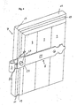
- Fig. 1Fig. 1
- eine Draufsicht auf einen unvollständig dargestellten Fensterladen mit einem Rahmenabschnitt, der den erfindungsgemäßen Scharnierbeschlag zeigt, in Explosionsdarstellung,a top view of an incomplete shutter with a frame portion showing the hinge fitting according to the invention, in an exploded view,
- Fig. 2Fig. 2
-
einen Querschnitt durch den Rahmenabschnitt und den befestigten Scharnierbeschlag gemäß
Fig. 1 in einer vergrößerten Darstellung,a cross section through the frame portion and the attached hinge fitting according toFig. 1 in an enlarged view, - Fig. 3Fig. 3
- eine Draufsicht auf einen unvollständig dargestellten Fensterladen mit dem erfindungsgemäß befestigten Scharnierbeschlag, unda plan view of an incomplete shutter with the inventively mounted hinge fitting, and
- Fig. 4Fig. 4
-
eine Darstellung nach
Fig. 3 in veränderter Perspektivea representation afterFig. 3 in a different perspective
In
Die nicht dargestellten Kloben greifen im montierten Zustand von unten in Hülse 3 ein, die zusammen mit den Kloben Scharniere bilden. Jede Hülse 3 ist Bestandteil eines Scharnierbeschlags 5, der es gestattet, den Fensterladen 1 je nach Bedarf in die Fensteröffnung hineinzuschwenken oder aus dieser um 180 Grad nach außen wegzuschwenken, um so die Fensteröffnung freizugeben.The clamps, not shown, engage in the assembled state from below in
Der Fensterladen 1 weist einen Rahmen 7 auf, der mittels verschiedener Strukturen wie Brettern 9, Lamellen o.a. gefüllt sein kann.The
Im Ausführungsbeispiel besteht der Rahmen 7 aus einem Aluminium-Rahmenprofil, mit einem dargestellten vertikalen Rahmenabschnitt 11 und einem horizontalen Rahmenabschnitt 13, die aus stranggepressten Profilen bestehen. Diese sind an vier Ecken 15 durch eine Eckverbindung in Gestalt einer Gehrung 17 miteinander verbunden. Dabei sind die Profile vorzugsweise im Querschnitt identisch. Eine Ecke 15 mit der entsprechenden Gehrung 17 ist in
In den Rahmenabschnitten 11, 13 ist eine umlaufende Vertiefung als Führung 19 integriert, die beidseitig in Längsrichtung hinterschnitten ist; sie dient zur Aufnahme und Führung eines Befestigungselementes, das insgesamt mit 21 bezeichnet ist. Das Befestigungselement 21 weist eine Basis 23 und einen Dorn 25 auf, der im Ausführungsbeispiel als ein Gewindezapfen ausgebildet ist.In the
Die Basis 23 ist breiter ausgebildet als der von ihr aufragende Dom 25, greift so in die durch die beidseitigen Hinterschneidungen gebildete Führung 19 ein und kann dadurch entlang des gesamten vertikalen Rahmenabschnitts 11 bis zur Gehrung geführt werden.
Im Bereich der Gehrung 17 trifft diese Führung 19 auf die entsprechend am horizontalen Rahmenabschnitt 13 ausgebildete Führung 19. Dadurch entsteht jeweils im Bereich des Zusammentreffens der jeweils vertikal und horizontal ausgebildeten Führungen 19 ein Stopp für die Basis 23 des Befestigungselements 21.The
In the region of the
Eine Öffnung in der die Führung 19 definierenden Vertiefung ist gerade so ausgebildet, daß der Dorn 25 in Form des Gewindezapfens aus ihr herausragt.An opening in the
Mit diesem Dom 25 wirkt der Scharnierbeschlag 5 zusammen, der eine Führungsplatte 27 aufweist und eine Abdeckplatte 29. Die Führungsplatte 27 weist ein Langloch 31 auf, durch das der Dorn 25 greift. Das Langloch 31 dient dazu, die Führungsplatte 27 bei der Befestigung an dem Fensterladen 1 zu justieren.With this
Wenn die Führungsplatte 27 den Dorn 25 aufnimmt und sich im Bereich einer Gehrung 17 befindet, schließt die jeweils in Richtung auf das Ende des Fensterladens weisende Begrenzung der Führungsplatte 27 in ihrer Längsrichtung in etwa mit der Begrenzung des Fensterladens 1 ab, da die Basis 23 des Befestigungselementes 21 bis in den Bereich der Gehrung 17 geführt werden kann.When the
Die Abdeckplatte 29 wird im Bereich des Langlochs 31 auf die Führungsplatte 27 aufgesetzt, die eine Vertiefung 33 zur Aufnahme der Führungsplatte 27 und ein Loch 35 zur Aufnahme des Doms 25 aufweist. An der Vertiefung 33 ist zusätzlich noch ein zahnartiger Vorsprung 34 ausgebildet, der gerade so bemessen ist, daß er in die Führung 19 eingreift. Dadurch wird der Scharnierbeschlag 5 bzw. die die Abdeckplatte 29 aufnehmende Führung 27 an dem Fensterladen 1 zusätzlich stabilisiert. Der zahnartige Vorsprung 34 ragt im Ausführungsbeispiel nicht mittig von der Vertiefung 33 weg, sondern ist seitlich versetzt angeordnet. Die genaue Position des zahnartigen Vorsprungs 34 ist jeweils abhängig von der Profilbreite des Rahmenabschnitts 11 von dessen Außenkante bis zu der Öffnung der Führung 19, die den Dom 25 aufnimmt.The
Im Ausführungsbeispiel weist die Führungsplatte 27 außerdem im Bereich des Langlochs 31 die Hülse 3 auf, die bei der Befestigung des Fensterladens am Mauerwerk den Kloben aufnimmt.In the exemplary embodiment, the
Mittels des Langlochs 31 kann die Führungsplatte 27 in der Vertiefung 33 quer zur Achse der Hülse 3 verschoben und damit eine horizontale Justierung des Fensterladens 1 vorgenommen werden.
Wenn die Justierung des Fensterladens 1 abgeschlossen ist, erfolgt die Arretierung, indem auf den durch Führungsplatte 27 und Abdeckplatte 29 ragenden Dom 25 in Form des Gewindezapfens eine Klemmutter 37 aufgesetzt und angezogen wird.By means of the
When the adjustment of the
Es ist nicht zwangsläufig erforderlich, den Dom 25 als Gewindezapfen in Zusammenwirkung mit einer Klemmmutter 37 vorzusehen. Dem Fachmann sind auch andere Möglichkeiten der Befestigung und Arretierung geläufig, die hier mit einbezogen sind.It is not necessarily required to provide the
In
Die
Die hier im Rahmen des Ausführungsbeispiels für einen Fensterrahmen erläuterte verbesserte schwenkbare Befestigung des Rahmens eines Fensterladens an Mauerwerk kann in der gleichen Weise auch für Türen angewendet werden.The illustrated here in the context of the embodiment of a window frame improved pivotal attachment of the frame of a shutter to masonry can be applied in the same way for doors.
Claims (11)
dadurch gekennzeichnet, daß die Basis (23) des Befestigungselements (21) insgesamt innerhalb einer entlang der Frontseite des Rahmenabschnittes (11) ausgebildeten Führung (19) verläuft, welche die Basis (23) vollständig aufnimmt, wobei die Führung (19) über ihre gesamte Länge eine Öffnung aufweist, die den Dorn (25) aufnimmt und aus welcher dieser nach außen ragt, so daß das Befestigungselement (21) entlang der Frontseite des Rahmenabschnittes (11) bis zu der an dessen Ende angeordneten Gehrung (17) führbar und feststellbar ist.Hinge fitting for the pivotable attachment of a frame (7), in particular the frame of a shutter (1) having four mutually perpendicular frame sections (11, 13) with at least one miter (17) having corner joint, on a counter fitting, with at least one a guide plate (27) which can be connected to the counter fitting and which can be clamped between a front side of one of the frame sections (11, 13) and a cover plate (29) which is displaceable along the frame section (11) and is positively connected to the front side of the frame section (11). 11) can be fastened, wherein the cover plate (29) is connectable to a fastening element (21) which is formed from a mandrel (25) and a base (23) which accommodates the latter,
characterized in that the base (23) of the fastener (21) extends generally within a guide (19) formed along the front of the frame portion (11) which fully receives the base (23), the guide (19) extending over its entire length Length has an opening which receives the mandrel (25) and from which this protrudes outwards, so that the fastening element (21) along the front side of the frame portion (11) to the arranged at the end miter (17) is feasible and lockable ,
Applications Claiming Priority (1)
| Application Number | Priority Date | Filing Date | Title |
|---|---|---|---|
| DE102007058130A DE102007058130B3 (en) | 2007-11-30 | 2007-11-30 | Hinge fitting for pivotally fixing the frame of a shutter |
Publications (4)
| Publication Number | Publication Date |
|---|---|
| EP2065546A2 true EP2065546A2 (en) | 2009-06-03 |
| EP2065546A3 EP2065546A3 (en) | 2010-05-05 |
| EP2065546B1 EP2065546B1 (en) | 2014-01-22 |
| EP2065546B2 EP2065546B2 (en) | 2021-02-17 |
Family
ID=39942391
Family Applications (1)
| Application Number | Title | Priority Date | Filing Date |
|---|---|---|---|
| EP08020799.6A Active EP2065546B2 (en) | 2007-11-30 | 2008-11-30 | Hinge fitting for pivotable mounting of the frame of a shutter |
Country Status (2)
| Country | Link |
|---|---|
| EP (1) | EP2065546B2 (en) |
| DE (1) | DE102007058130B3 (en) |
Cited By (1)
| Publication number | Priority date | Publication date | Assignee | Title |
|---|---|---|---|---|
| DE202017102387U1 (en) | 2017-04-21 | 2017-05-11 | Pfeifer Beschläge GmbH & Co. KG | A hinge fitting |
Families Citing this family (3)
| Publication number | Priority date | Publication date | Assignee | Title |
|---|---|---|---|---|
| DE102008016929B3 (en) * | 2008-04-01 | 2009-05-20 | Kunz, Bernhard | Fastening device for bands |
| FR2962150A1 (en) * | 2010-07-01 | 2012-01-06 | Volets Production | Shutter wing for opening e.g. door, has reverse piece and/or housing comprising blocking unit that is arranged for blocking position of reverse piece in housing, where reverse piece is arranged in interior of frame |
| DE202012100985U1 (en) * | 2012-03-19 | 2013-06-25 | Pfeifer Beschläge GmbH & Co. KG | fastening device |
Citations (3)
| Publication number | Priority date | Publication date | Assignee | Title |
|---|---|---|---|---|
| AT411842B (en) | 2002-07-15 | 2004-06-25 | Ast Alu System Technik Gesmbh | FITTING FOR AN ALUMINUM WINDOW LOAD |
| DE102005053650B3 (en) | 2005-11-10 | 2006-11-23 | W.S.T. Wetter-Schutz-Technik Kunz Bernhard | Hinge for aluminium window frame has hinge tube mounted on plate with profiled clamp to engage edge of window frame |
| DE102006020071B3 (en) | 2006-04-29 | 2007-04-12 | W.S.T. Wetter-Schutz-Technik Kunz Bernhard | Decorative hinge-clasp for hinged window shutter frame, uses guide plate clamped between front of frame section and cover plate |
Family Cites Families (2)
| Publication number | Priority date | Publication date | Assignee | Title |
|---|---|---|---|---|
| DE2033040A1 (en) * | 1970-07-03 | 1972-01-13 | Siegenia-Frank KG, 5900 Siegen-Kaan-Marienborn | Fastening means for building fittings on metal or plastic hollow profiles, in particular for door and window sashes and frames |
| EP1659246A1 (en) † | 2004-11-23 | 2006-05-24 | Fritz Fuhrimann | Hinge for shutters |
-
2007
- 2007-11-30 DE DE102007058130A patent/DE102007058130B3/en active Active
-
2008
- 2008-11-30 EP EP08020799.6A patent/EP2065546B2/en active Active
Patent Citations (3)
| Publication number | Priority date | Publication date | Assignee | Title |
|---|---|---|---|---|
| AT411842B (en) | 2002-07-15 | 2004-06-25 | Ast Alu System Technik Gesmbh | FITTING FOR AN ALUMINUM WINDOW LOAD |
| DE102005053650B3 (en) | 2005-11-10 | 2006-11-23 | W.S.T. Wetter-Schutz-Technik Kunz Bernhard | Hinge for aluminium window frame has hinge tube mounted on plate with profiled clamp to engage edge of window frame |
| DE102006020071B3 (en) | 2006-04-29 | 2007-04-12 | W.S.T. Wetter-Schutz-Technik Kunz Bernhard | Decorative hinge-clasp for hinged window shutter frame, uses guide plate clamped between front of frame section and cover plate |
Cited By (1)
| Publication number | Priority date | Publication date | Assignee | Title |
|---|---|---|---|---|
| DE202017102387U1 (en) | 2017-04-21 | 2017-05-11 | Pfeifer Beschläge GmbH & Co. KG | A hinge fitting |
Also Published As
| Publication number | Publication date |
|---|---|
| DE102007058130B3 (en) | 2008-12-11 |
| EP2065546A3 (en) | 2010-05-05 |
| EP2065546B1 (en) | 2014-01-22 |
| EP2065546B2 (en) | 2021-02-17 |
Similar Documents
| Publication | Publication Date | Title |
|---|---|---|
| DE102005057397A1 (en) | Multi-purpose profiles for the assembly of frames, fixtures, structural parts and the like | |
| DE202013101519U1 (en) | Shower door assembly | |
| DE102009012438A1 (en) | pinheader | |
| EP2065546B1 (en) | Hinge fitting for pivotable mounting of the frame of a shutter | |
| DE8010921U1 (en) | HINGEBAND CONNECTION FOR WINDOWS, DOORS AND GATES | |
| AT515020B1 (en) | Sill-line unit | |
| EP2927409B1 (en) | Sealing arrangement for a push door | |
| EP1849944B1 (en) | Hinge fitting for pivotable mounting of a frame, especially a frame of a shutter | |
| EP1659246A1 (en) | Hinge for shutters | |
| EP2935742A1 (en) | Door system | |
| EP3118404A1 (en) | Hinge, in particular for plastic doors and plastic windows | |
| DE102008016929B3 (en) | Fastening device for bands | |
| DE102005053650B3 (en) | Hinge for aluminium window frame has hinge tube mounted on plate with profiled clamp to engage edge of window frame | |
| EP1256681B1 (en) | Fitting for a closure element for a wall opening | |
| EP2320022B1 (en) | Hinge for an insect and/or pollen protection screen | |
| DE202009003438U1 (en) | pinheader | |
| DE602004003430T2 (en) | Device for fastening a band to a wing | |
| EP1001124A1 (en) | Hinge fitting for a shutter | |
| DE202005003011U1 (en) | Brace for erecting fences and rails has groove(s) in outer surface that is vertical at least in mounted state with mounting element(s) with preferably flat mounting surface that can be pivoted around vertical axis in mounted state | |
| EP1243212B1 (en) | Shower partition | |
| DE202015100628U1 (en) | Frame for a door or a window | |
| DE202013103663U1 (en) | Mounting frame for sliding doors | |
| EP3653826B1 (en) | Fastening means for fixing frames for windows, doors, gates or facades, method and arrangement | |
| DE2033040A1 (en) | Fastening means for building fittings on metal or plastic hollow profiles, in particular for door and window sashes and frames | |
| EP2108774A1 (en) | Hinge |
Legal Events
| Date | Code | Title | Description |
|---|---|---|---|
| PUAI | Public reference made under article 153(3) epc to a published international application that has entered the european phase |
Free format text: ORIGINAL CODE: 0009012 |
|
| AK | Designated contracting states |
Kind code of ref document: A2 Designated state(s): AT BE BG CH CY CZ DE DK EE ES FI FR GB GR HR HU IE IS IT LI LT LU LV MC MT NL NO PL PT RO SE SI SK TR |
|
| AX | Request for extension of the european patent |
Extension state: AL BA MK RS |
|
| PUAL | Search report despatched |
Free format text: ORIGINAL CODE: 0009013 |
|
| AK | Designated contracting states |
Kind code of ref document: A3 Designated state(s): AT BE BG CH CY CZ DE DK EE ES FI FR GB GR HR HU IE IS IT LI LT LU LV MC MT NL NO PL PT RO SE SI SK TR |
|
| AX | Request for extension of the european patent |
Extension state: AL BA MK RS |
|
| 17P | Request for examination filed |
Effective date: 20101104 |
|
| AKX | Designation fees paid |
Designated state(s): AT BE BG CH CY CZ DE DK EE ES FI FR GB GR HR HU IE IS IT LI LT LU LV MC MT NL NO PL PT RO SE SI SK TR |
|
| RAP1 | Party data changed (applicant data changed or rights of an application transferred) |
Owner name: KUNZ, TOBIAS Owner name: KUNZ, BERNHARD |
|
| 17Q | First examination report despatched |
Effective date: 20110518 |
|
| RAP1 | Party data changed (applicant data changed or rights of an application transferred) |
Owner name: SCHENKER STOREN AG |
|
| GRAP | Despatch of communication of intention to grant a patent |
Free format text: ORIGINAL CODE: EPIDOSNIGR1 |
|
| INTG | Intention to grant announced |
Effective date: 20130801 |
|
| GRAS | Grant fee paid |
Free format text: ORIGINAL CODE: EPIDOSNIGR3 |
|
| GRAA | (expected) grant |
Free format text: ORIGINAL CODE: 0009210 |
|
| AK | Designated contracting states |
Kind code of ref document: B1 Designated state(s): AT BE BG CH CY CZ DE DK EE ES FI FR GB GR HR HU IE IS IT LI LT LU LV MC MT NL NO PL PT RO SE SI SK TR |
|
| REG | Reference to a national code |
Ref country code: GB Ref legal event code: FG4D Free format text: NOT ENGLISH |
|
| REG | Reference to a national code |
Ref country code: CH Ref legal event code: EP |
|
| REG | Reference to a national code |
Ref country code: AT Ref legal event code: REF Ref document number: 650922 Country of ref document: AT Kind code of ref document: T Effective date: 20140215 |
|
| REG | Reference to a national code |
Ref country code: IE Ref legal event code: FG4D Free format text: LANGUAGE OF EP DOCUMENT: GERMAN |
|
| REG | Reference to a national code |
Ref country code: DE Ref legal event code: R096 Ref document number: 502008011262 Country of ref document: DE Effective date: 20140227 |
|
| REG | Reference to a national code |
Ref country code: CH Ref legal event code: NV Representative=s name: E. BLUM AND CO. AG PATENT- UND MARKENANWAELTE , CH |
|
| REG | Reference to a national code |
Ref country code: NL Ref legal event code: VDEP Effective date: 20140122 |
|
| REG | Reference to a national code |
Ref country code: LT Ref legal event code: MG4D |
|
| PG25 | Lapsed in a contracting state [announced via postgrant information from national office to epo] |
Ref country code: IS Free format text: LAPSE BECAUSE OF FAILURE TO SUBMIT A TRANSLATION OF THE DESCRIPTION OR TO PAY THE FEE WITHIN THE PRESCRIBED TIME-LIMIT Effective date: 20140522 Ref country code: NO Free format text: LAPSE BECAUSE OF FAILURE TO SUBMIT A TRANSLATION OF THE DESCRIPTION OR TO PAY THE FEE WITHIN THE PRESCRIBED TIME-LIMIT Effective date: 20140422 Ref country code: LT Free format text: LAPSE BECAUSE OF FAILURE TO SUBMIT A TRANSLATION OF THE DESCRIPTION OR TO PAY THE FEE WITHIN THE PRESCRIBED TIME-LIMIT Effective date: 20140122 |
|
| REG | Reference to a national code |
Ref country code: DE Ref legal event code: R082 Ref document number: 502008011262 Country of ref document: DE Representative=s name: FROHWITTER PATENT- UND RECHTSANWAELTE, DE |
|
| PG25 | Lapsed in a contracting state [announced via postgrant information from national office to epo] |
Ref country code: ES Free format text: LAPSE BECAUSE OF FAILURE TO SUBMIT A TRANSLATION OF THE DESCRIPTION OR TO PAY THE FEE WITHIN THE PRESCRIBED TIME-LIMIT Effective date: 20140122 Ref country code: SE Free format text: LAPSE BECAUSE OF FAILURE TO SUBMIT A TRANSLATION OF THE DESCRIPTION OR TO PAY THE FEE WITHIN THE PRESCRIBED TIME-LIMIT Effective date: 20140122 Ref country code: CY Free format text: LAPSE BECAUSE OF FAILURE TO SUBMIT A TRANSLATION OF THE DESCRIPTION OR TO PAY THE FEE WITHIN THE PRESCRIBED TIME-LIMIT Effective date: 20140122 Ref country code: PT Free format text: LAPSE BECAUSE OF FAILURE TO SUBMIT A TRANSLATION OF THE DESCRIPTION OR TO PAY THE FEE WITHIN THE PRESCRIBED TIME-LIMIT Effective date: 20140522 Ref country code: NL Free format text: LAPSE BECAUSE OF FAILURE TO SUBMIT A TRANSLATION OF THE DESCRIPTION OR TO PAY THE FEE WITHIN THE PRESCRIBED TIME-LIMIT Effective date: 20140122 Ref country code: FI Free format text: LAPSE BECAUSE OF FAILURE TO SUBMIT A TRANSLATION OF THE DESCRIPTION OR TO PAY THE FEE WITHIN THE PRESCRIBED TIME-LIMIT Effective date: 20140122 |
|
| REG | Reference to a national code |
Ref country code: DE Ref legal event code: R081 Ref document number: 502008011262 Country of ref document: DE Owner name: EHRET GMBH, DE Free format text: FORMER OWNER: SCHENKER STOREN AG, SCHOENENWERD, CH Effective date: 20140731 Ref country code: DE Ref legal event code: R082 Ref document number: 502008011262 Country of ref document: DE Representative=s name: FROHWITTER PATENT- UND RECHTSANWAELTE, DE Effective date: 20140731 |
|
| PG25 | Lapsed in a contracting state [announced via postgrant information from national office to epo] |
Ref country code: LV Free format text: LAPSE BECAUSE OF FAILURE TO SUBMIT A TRANSLATION OF THE DESCRIPTION OR TO PAY THE FEE WITHIN THE PRESCRIBED TIME-LIMIT Effective date: 20140122 Ref country code: HR Free format text: LAPSE BECAUSE OF FAILURE TO SUBMIT A TRANSLATION OF THE DESCRIPTION OR TO PAY THE FEE WITHIN THE PRESCRIBED TIME-LIMIT Effective date: 20140122 |
|
| REG | Reference to a national code |
Ref country code: DE Ref legal event code: R026 Ref document number: 502008011262 Country of ref document: DE |
|
| PLBI | Opposition filed |
Free format text: ORIGINAL CODE: 0009260 |
|
| PG25 | Lapsed in a contracting state [announced via postgrant information from national office to epo] |
Ref country code: EE Free format text: LAPSE BECAUSE OF FAILURE TO SUBMIT A TRANSLATION OF THE DESCRIPTION OR TO PAY THE FEE WITHIN THE PRESCRIBED TIME-LIMIT Effective date: 20140122 Ref country code: RO Free format text: LAPSE BECAUSE OF FAILURE TO SUBMIT A TRANSLATION OF THE DESCRIPTION OR TO PAY THE FEE WITHIN THE PRESCRIBED TIME-LIMIT Effective date: 20140122 Ref country code: DK Free format text: LAPSE BECAUSE OF FAILURE TO SUBMIT A TRANSLATION OF THE DESCRIPTION OR TO PAY THE FEE WITHIN THE PRESCRIBED TIME-LIMIT Effective date: 20140122 Ref country code: CZ Free format text: LAPSE BECAUSE OF FAILURE TO SUBMIT A TRANSLATION OF THE DESCRIPTION OR TO PAY THE FEE WITHIN THE PRESCRIBED TIME-LIMIT Effective date: 20140122 |
|
| 26 | Opposition filed |
Opponent name: PFEIFER BESCHLAEGE GMBH & CO. KG Effective date: 20141022 |
|
| PG25 | Lapsed in a contracting state [announced via postgrant information from national office to epo] |
Ref country code: SK Free format text: LAPSE BECAUSE OF FAILURE TO SUBMIT A TRANSLATION OF THE DESCRIPTION OR TO PAY THE FEE WITHIN THE PRESCRIBED TIME-LIMIT Effective date: 20140122 Ref country code: PL Free format text: LAPSE BECAUSE OF FAILURE TO SUBMIT A TRANSLATION OF THE DESCRIPTION OR TO PAY THE FEE WITHIN THE PRESCRIBED TIME-LIMIT Effective date: 20140122 |
|
| PLAX | Notice of opposition and request to file observation + time limit sent |
Free format text: ORIGINAL CODE: EPIDOSNOBS2 |
|
| REG | Reference to a national code |
Ref country code: DE Ref legal event code: R026 Ref document number: 502008011262 Country of ref document: DE Effective date: 20141022 |
|
| PLAF | Information modified related to communication of a notice of opposition and request to file observations + time limit |
Free format text: ORIGINAL CODE: EPIDOSCOBS2 |
|
| PG25 | Lapsed in a contracting state [announced via postgrant information from national office to epo] |
Ref country code: SI Free format text: LAPSE BECAUSE OF FAILURE TO SUBMIT A TRANSLATION OF THE DESCRIPTION OR TO PAY THE FEE WITHIN THE PRESCRIBED TIME-LIMIT Effective date: 20140122 |
|
| PG25 | Lapsed in a contracting state [announced via postgrant information from national office to epo] |
Ref country code: LU Free format text: LAPSE BECAUSE OF FAILURE TO SUBMIT A TRANSLATION OF THE DESCRIPTION OR TO PAY THE FEE WITHIN THE PRESCRIBED TIME-LIMIT Effective date: 20141130 Ref country code: MC Free format text: LAPSE BECAUSE OF FAILURE TO SUBMIT A TRANSLATION OF THE DESCRIPTION OR TO PAY THE FEE WITHIN THE PRESCRIBED TIME-LIMIT Effective date: 20140122 Ref country code: BE Free format text: LAPSE BECAUSE OF NON-PAYMENT OF DUE FEES Effective date: 20141130 |
|
| PLBB | Reply of patent proprietor to notice(s) of opposition received |
Free format text: ORIGINAL CODE: EPIDOSNOBS3 |
|
| GBPC | Gb: european patent ceased through non-payment of renewal fee |
Effective date: 20141130 |
|
| REG | Reference to a national code |
Ref country code: IE Ref legal event code: MM4A |
|
| PG25 | Lapsed in a contracting state [announced via postgrant information from national office to epo] |
Ref country code: GB Free format text: LAPSE BECAUSE OF NON-PAYMENT OF DUE FEES Effective date: 20141130 Ref country code: IE Free format text: LAPSE BECAUSE OF NON-PAYMENT OF DUE FEES Effective date: 20141130 |
|
| REG | Reference to a national code |
Ref country code: FR Ref legal event code: PLFP Year of fee payment: 8 |
|
| REG | Reference to a national code |
Ref country code: AT Ref legal event code: MM01 Ref document number: 650922 Country of ref document: AT Kind code of ref document: T Effective date: 20141130 |
|
| PG25 | Lapsed in a contracting state [announced via postgrant information from national office to epo] |
Ref country code: AT Free format text: LAPSE BECAUSE OF NON-PAYMENT OF DUE FEES Effective date: 20141130 |
|
| PG25 | Lapsed in a contracting state [announced via postgrant information from national office to epo] |
Ref country code: BG Free format text: LAPSE BECAUSE OF FAILURE TO SUBMIT A TRANSLATION OF THE DESCRIPTION OR TO PAY THE FEE WITHIN THE PRESCRIBED TIME-LIMIT Effective date: 20140122 |
|
| PG25 | Lapsed in a contracting state [announced via postgrant information from national office to epo] |
Ref country code: GR Free format text: LAPSE BECAUSE OF FAILURE TO SUBMIT A TRANSLATION OF THE DESCRIPTION OR TO PAY THE FEE WITHIN THE PRESCRIBED TIME-LIMIT Effective date: 20140122 Ref country code: IT Free format text: LAPSE BECAUSE OF FAILURE TO SUBMIT A TRANSLATION OF THE DESCRIPTION OR TO PAY THE FEE WITHIN THE PRESCRIBED TIME-LIMIT Effective date: 20140122 |
|
| PG25 | Lapsed in a contracting state [announced via postgrant information from national office to epo] |
Ref country code: HU Free format text: LAPSE BECAUSE OF FAILURE TO SUBMIT A TRANSLATION OF THE DESCRIPTION OR TO PAY THE FEE WITHIN THE PRESCRIBED TIME-LIMIT; INVALID AB INITIO Effective date: 20081130 Ref country code: MT Free format text: LAPSE BECAUSE OF FAILURE TO SUBMIT A TRANSLATION OF THE DESCRIPTION OR TO PAY THE FEE WITHIN THE PRESCRIBED TIME-LIMIT Effective date: 20140122 Ref country code: TR Free format text: LAPSE BECAUSE OF FAILURE TO SUBMIT A TRANSLATION OF THE DESCRIPTION OR TO PAY THE FEE WITHIN THE PRESCRIBED TIME-LIMIT Effective date: 20140122 |
|
| REG | Reference to a national code |
Ref country code: FR Ref legal event code: PLFP Year of fee payment: 9 |
|
| REG | Reference to a national code |
Ref country code: CH Ref legal event code: PUE Owner name: EHRET GMBH, DE Free format text: FORMER OWNER: SCHENKER STOREN AG, CH |
|
| PLAB | Opposition data, opponent's data or that of the opponent's representative modified |
Free format text: ORIGINAL CODE: 0009299OPPO |
|
| RAP2 | Party data changed (patent owner data changed or rights of a patent transferred) |
Owner name: EHRET GMBH |
|
| REG | Reference to a national code |
Ref country code: FR Ref legal event code: TP Owner name: EHRET GMBH, DE Effective date: 20170315 |
|
| APBM | Appeal reference recorded |
Free format text: ORIGINAL CODE: EPIDOSNREFNO |
|
| APBP | Date of receipt of notice of appeal recorded |
Free format text: ORIGINAL CODE: EPIDOSNNOA2O |
|
| R26 | Opposition filed (corrected) |
Opponent name: PFEIFER BESCHLAEGE GMBH & CO. KG Effective date: 20141022 |
|
| APAH | Appeal reference modified |
Free format text: ORIGINAL CODE: EPIDOSCREFNO |
|
| APBQ | Date of receipt of statement of grounds of appeal recorded |
Free format text: ORIGINAL CODE: EPIDOSNNOA3O |
|
| REG | Reference to a national code |
Ref country code: FR Ref legal event code: PLFP Year of fee payment: 10 |
|
| APBU | Appeal procedure closed |
Free format text: ORIGINAL CODE: EPIDOSNNOA9O |
|
| PUAH | Patent maintained in amended form |
Free format text: ORIGINAL CODE: 0009272 |
|
| STAA | Information on the status of an ep patent application or granted ep patent |
Free format text: STATUS: PATENT MAINTAINED AS AMENDED |
|
| REG | Reference to a national code |
Ref country code: CH Ref legal event code: AELC |
|
| 27A | Patent maintained in amended form |
Effective date: 20210217 |
|
| AK | Designated contracting states |
Kind code of ref document: B2 Designated state(s): AT BE BG CH CY CZ DE DK EE ES FI FR GB GR HR HU IE IS IT LI LT LU LV MC MT NL NO PL PT RO SE SI SK TR |
|
| REG | Reference to a national code |
Ref country code: DE Ref legal event code: R102 Ref document number: 502008011262 Country of ref document: DE |
|
| PGFP | Annual fee paid to national office [announced via postgrant information from national office to epo] |
Ref country code: FR Payment date: 20231228 Year of fee payment: 16 |
|
| PGFP | Annual fee paid to national office [announced via postgrant information from national office to epo] |
Ref country code: DE Payment date: 20240130 Year of fee payment: 16 Ref country code: CH Payment date: 20240127 Year of fee payment: 16 |