EP2065082A1 - Air cleaning device - Google Patents
Air cleaning device Download PDFInfo
- Publication number
- EP2065082A1 EP2065082A1 EP08010573A EP08010573A EP2065082A1 EP 2065082 A1 EP2065082 A1 EP 2065082A1 EP 08010573 A EP08010573 A EP 08010573A EP 08010573 A EP08010573 A EP 08010573A EP 2065082 A1 EP2065082 A1 EP 2065082A1
- Authority
- EP
- European Patent Office
- Prior art keywords
- cleaning device
- air cleaning
- distributor
- housing
- supply pipe
- Prior art date
- Legal status (The legal status is an assumption and is not a legal conclusion. Google has not performed a legal analysis and makes no representation as to the accuracy of the status listed.)
- Withdrawn
Links
Images

Classifications
-
- B—PERFORMING OPERATIONS; TRANSPORTING
- B01—PHYSICAL OR CHEMICAL PROCESSES OR APPARATUS IN GENERAL
- B01D—SEPARATION
- B01D47/00—Separating dispersed particles from gases, air or vapours by liquid as separating agent
- B01D47/06—Spray cleaning
-
- F—MECHANICAL ENGINEERING; LIGHTING; HEATING; WEAPONS; BLASTING
- F24—HEATING; RANGES; VENTILATING
- F24F—AIR-CONDITIONING; AIR-HUMIDIFICATION; VENTILATION; USE OF AIR CURRENTS FOR SCREENING
- F24F8/00—Treatment, e.g. purification, of air supplied to human living or working spaces otherwise than by heating, cooling, humidifying or drying
- F24F8/10—Treatment, e.g. purification, of air supplied to human living or working spaces otherwise than by heating, cooling, humidifying or drying by separation, e.g. by filtering
- F24F8/117—Treatment, e.g. purification, of air supplied to human living or working spaces otherwise than by heating, cooling, humidifying or drying by separation, e.g. by filtering using wet filtering
- F24F8/133—Treatment, e.g. purification, of air supplied to human living or working spaces otherwise than by heating, cooling, humidifying or drying by separation, e.g. by filtering using wet filtering by direct contact with liquid, e.g. with sprayed liquid
-
- F—MECHANICAL ENGINEERING; LIGHTING; HEATING; WEAPONS; BLASTING
- F24—HEATING; RANGES; VENTILATING
- F24F—AIR-CONDITIONING; AIR-HUMIDIFICATION; VENTILATION; USE OF AIR CURRENTS FOR SCREENING
- F24F8/00—Treatment, e.g. purification, of air supplied to human living or working spaces otherwise than by heating, cooling, humidifying or drying
- F24F8/10—Treatment, e.g. purification, of air supplied to human living or working spaces otherwise than by heating, cooling, humidifying or drying by separation, e.g. by filtering
- F24F8/117—Treatment, e.g. purification, of air supplied to human living or working spaces otherwise than by heating, cooling, humidifying or drying by separation, e.g. by filtering using wet filtering
-
- Y—GENERAL TAGGING OF NEW TECHNOLOGICAL DEVELOPMENTS; GENERAL TAGGING OF CROSS-SECTIONAL TECHNOLOGIES SPANNING OVER SEVERAL SECTIONS OF THE IPC; TECHNICAL SUBJECTS COVERED BY FORMER USPC CROSS-REFERENCE ART COLLECTIONS [XRACs] AND DIGESTS
- Y02—TECHNOLOGIES OR APPLICATIONS FOR MITIGATION OR ADAPTATION AGAINST CLIMATE CHANGE
- Y02A—TECHNOLOGIES FOR ADAPTATION TO CLIMATE CHANGE
- Y02A50/00—TECHNOLOGIES FOR ADAPTATION TO CLIMATE CHANGE in human health protection, e.g. against extreme weather
- Y02A50/20—Air quality improvement or preservation, e.g. vehicle emission control or emission reduction by using catalytic converters
Definitions
- the invention relates to a distributor nozzle device for a filter device of an air cleaning device, a filter device for an air cleaning device and an air cleaning device according to the preamble of claim 1, claim 20 and claim 21.
- DE-U1-203 02 152 proposes a mobile air-cleaning blower that washes the dust and dirt particles out of the air using water. It has for this purpose a first shaft with lateral air inlet openings for the contaminated air and parallel thereto a second shaft with an air outlet opening for the purified air. In a transition region between the first and the second shaft, a water curtain is created with a horizontally disposed, longitudinally slotted tube to wash out the dust and dirt particles from the sucked by the fan air. The entire device is in a water trough, from which the water for the production of the water curtain promoted and in which the spent water is returned.
- the disadvantage here is that the fan pushes the air flow through a flat, relatively thin water curtain, so that it is blown apart like a curtain in places. Dust particles within the air flow are therefore not or only insufficiently moistened and thus not washed out.
- the entire device is relatively large and unwieldy. It consists of a total of two bulky parts, namely a cuboidal housing part and a rectangular tower tower with the air exhaust openings.
- the water tank as a reservoir and collection container for the liquid medium. All parts must be transported individually and reassembled each time. The labor and assembly costs are correspondingly high. The design effort leads to relatively high production costs.
- an air cleaning device known as a suction device. It consists of two coaxially arranged metal tubes, namely an outer tube and an inner tube, which are located in a tub filled with water. On the inner tube, a fan is attached, which closes circumferentially tight with the outer tube. In the lower part of the pipes is a water pump with a riser. This sits centrally in the inner tube and ends just before the outlet opening of the fan. There is a mushroom-shaped attachment provided by the pump conveyed water deflects outwards and downwards. Lateral openings in the outer and inner tube are used for flowing out of the cleaned air, wherein the openings are arranged opposite each other and offset in height, so that neither water nor dust can escape from the device.
- Such a device is very handy. However, it has the disadvantage that it is limited in terms of capacity of the ambient air to be cleaned and is not designed for large amounts of recirculated air to be cleaned.
- the aim of the invention is to overcome these and other disadvantages of the prior art and to provide a flexibly formed air cleaning device, which is improved in terms of their operation over the prior art and is designed especially for large amounts of air to be cleaned. Therefore, the aim is in particular an improved distributor nozzle device and an improved filter device.
- These should, as well as the air cleaning system, be overall simple and inexpensive. The entire system should be easy to handle and easy to dismantle and reassemble.
- the technical teaching of the present invention provides that, in the case of a distributor nozzle device for a filter device of an air cleaning device, for atomized distribution of a liquid medium in an air stream drawn in from the environment, it is provided that the distributor nozzle device is designed in multiple stages with at least two plate-nozzle-like distributor nozzles.
- the multistage is effected by a downstream arrangement of at least two distributor nozzles.
- the distributor nozzles can be of the same design or differ in terms of size, flow rate, discharge quantity, flow cross section, shape, structure, pressure distribution, flow rate and the like.
- the distributor nozzles each have a supply pipe line section with an outlet opening and a spaced-apart, in particular plate-shaped, dome-shaped or bell-shaped impact body, spaced apart from the outlet opening.
- the supply pipe may be formed as a pipe section with an outer wall and a line section surrounding the outer wall.
- the supply pipe can have any cross-section, more specifically a flow cross-section, preferably a circular cross-section.
- the baffle body is designed such that the liquid medium bouncing through the outlet opening onto the baffle body is distributed substantially laterally away and / or at an angle directed downwards and / or upwards in the air flow from the outlet opening is.
- the baffle thus acts as a deflecting and / or atomizing body.
- the baffle body deflects the impinging liquid medium, preferably circumferentially and / or at an angle in the range of> 0 ° and ⁇ 180 ° to a pipeline axis, and on the other hand the baffle body distributes or atomizes the impacting liquid medium, so as to create a kind of curtain from the liquid medium comprising medium droplets, medium mist and / or medium jets.
- the impact body on a corresponding baffle or corresponding baffles on which impinges the medium coming from the outlet opening is arranged so that they allow a deflection and a distribution of the medium beam.
- the baffles are preferably aligned inclined to the pipe axis.
- the baffle body and thus also the baffle surface are formed substantially rotationally symmetrical about a baffle center axis in order to effect an approximately rotationally symmetrical uniform distribution of the liquid medium. In this way, a dense medium curtain is created and the impact body is easy to produce.
- the bumper centerline is coaxially and / or aligned in extension to a feed tube section central axis. Due to the symmetrical arrangement, a uniform medium curtain can be realized.
- the supply pipe section of at least the first stage distributor nozzle is connectable to a supply pipe or riser of the filter device of the air cleaner. Via the feed tube, the liquid medium from a source, preferably pressurized, to the first dispensing nozzle, as viewed in the direction of flow of the medium supplied.
- the supply pipe section can be materially, positively and / or non-positively connected to the supply pipe, preferably sealed.
- the feed pipe sections of the downstream distributor nozzles are preferred each formed opposite to the supply pipe sections of the upstream distributor nozzles in the circumferential direction smaller. In this way, the adjacent supply pipe sections can be plugged into each other. In addition, a uniform and / or regulated supply of the medium to the downstream distributor nozzles can be realized via a suitable size dimension.
- each of the supply pipe section of a distributor nozzle connected downstream of the first distributor nozzle projects at least partially into the supply pipe section of the respectively upstream distributor nozzle.
- the supply pipe sections are inserted into one another in the manner of a telescope, wherein in each case at least one gap defining the outlet opening is formed between the supply pipe sections in the circumferential direction.
- the mutually projecting supply pipe sections are aligned with each other so that the corresponding outlet opening of the corresponding feed pipe section is formed approximately in the form of a gap or a ring, that is to say a play in the circumferential direction.
- the gap is annular.
- the feed pipe sections are preferably aligned concentrically with one another. With other geometries, corresponding gap-shaped openings result.
- the center axes of the corresponding feed pipe sections are formed substantially coaxially with each other.
- the feed pipe sections of a plurality of distributor nozzles can be connected to a feed pipe or riser pipe of the filter device of the air cleaning device.
- the individual feed pipe sections are not arranged inside each other, but branched off as separate arms or branching from the (main) supply pipe.
- the supply pipe sections may have a constant flow cross section at least in sections along their center axes.
- the supply pipe sections may be approximately cylindrical.
- the supply pipe sections could also be partially cylindrical, for example, with several sections with different but constant diameters, so be formed stepped.
- the supply pipe sections have a variable flow cross-section along their central axes.
- the supply pipe sections may be approximately tapered or widening, for example, to provide a corresponding pressure ratio at the corresponding outlet opening.
- the supply pipe sections are arranged fixed to one another by means of corresponding holding devices. In this way, a relative movement of the supply pipe sections to each other is prevented and a once set pressure ratio or a gap can be maintained.
- the length of the supply pipe sections of at least two distribution nozzles along their central axes may be formed differently. As a result, a medium curtain to be generated can be adapted to corresponding ambient geometries.
- the feed pipe sections protruding into one another are all fixed to one another by means of a single holding device. That is, the feed pipe sections begin or end substantially in a plane in the holding device and are of different lengths.
- the holding device is preferably designed as a web arranged in a feed pipe section of the first distributing nozzle and past which the liquid medium can flow.
- An embodiment of the present invention provides that the impact body of the last stage, that is, the last distributor nozzle in the flow direction, via a holding rod with the filter device of the air cleaning device is connectable.
- the support rod can penetrate the impact body and protrude into the corresponding feed pipe section.
- At least one further baffle body, preferably all other baffle bodies, that is to say all baffle bodies with the exception of the baffle body of the last stage, are preferably attached to the feed pipe sections of the downstream distributor nozzles. In this way, a stable distributor nozzle device is ensured.
- the technical teaching of the present invention further provides that in a filter device for an air cleaning device, with a distributor nozzle device according to the invention for the atomized distribution of a liquid medium in one of the Envisaged intake air flow is provided, that the filter device can be used in an air cleaning device.
- the filter device is fed via a feed line with a fluid or liquid medium, preferably with water, which is pressurized.
- the filter device has a distributor nozzle device.
- the distributor nozzle device which distributes the liquid medium atomized into the air flow, comprises a plurality of distributor nozzles.
- Each distributor nozzle has a feed pipe section, wherein at an end of the distributor nozzle facing away from the feed pipe section, an impact body is provided, which is arranged at a distance from the feed pipe section and thus forms a gap for the escape of the liquid medium.
- a corresponding recesses is formed to introduce the liquid medium through this in the air flow.
- a slot-shaped or annular recess shape As a result, a particularly suitable "fog" of liquid medium in the air flow can bring.
- the distributor nozzle device or in each case the distributor nozzle has a longitudinal axis or central axis.
- the recesses of the distributor nozzles for distributing the liquid medium in the air flow are at least partially formed as gaps or circumferential openings, which are concentrically extending slots or openings, recesses and the like relative to the axis. This makes it possible to realize a suitable introduction of the liquid medium into the air stream. The consumption of liquid medium in terms of the quality of cleaning is thus optimized.
- the recesses can be produced inexpensively and easily.
- the technical teaching of the present invention further provides that in an air cleaning device for removing dust and / or dirt from an ambient air, a housing, in which a cleaning device is accommodated with a filter device according to the invention, a suction device, which sucks a polluted ambient air, a conduit means extending from an exit port of the aspirator to an inlet port of the housing and an outlet means are provided, ambient air being passed via the conduit means from the aspirator into the housing through the purifier and the fluid traversed by the purifier purified via an exhaust port the outlet is blown out.
- the air cleaning device is thus constructed modular, wherein the individual modules are connected to each other via at least one conduit means.
- components for large amounts of air to be cleaned can be used without being limited in size by a common housing.
- the device can also be easily dismantled and reassembled. New components can always be used so that the device is adaptable to the advancing development.
- the cleaning device is fixed by the filter device and a housing section with a through-opening through which the air sucked in, which surrounds at least part of the filter device.
- the housing section represents the outer boundary through which the air flow is moved, and thus forms a channel for the ambient air to be cleaned.
- the filter device is designed such that the liquid medium introduced from the distributor nozzle device into the air stream occupies the entire cross section in a plan view in the direction of a longitudinal axis through the channel, so that all the air passes through the (multi-level) curtain or mist produced by the liquid medium got to.
- the atomized liquid medium can be distributed over the cross-sectional area of the passage opening of the housing section of the cleaning device.
- the (main) flow direction of the medium substantially coincides with the flow direction of the air flow. This prevents on the one hand that the liquid medium can penetrate into the fan. On the other hand, the medium almost completely penetrates the air flow coming from the fan, without, however, blowing it apart, so that even the smallest dust particles are also caught and flushed out of the medium inside the air flow.
- the atomized liquid medium forms a mist stream extending and / or expanding longitudinally and transversely to an axis extending through the passage opening. This ensures intensive contact between the atomized medium and the ambient air to be cleaned in a relatively large volume, whereby a high degree of purification is always ensured.
- the air flow extends at least in sections coaxially with the longitudinal axis of the housing section, which further simplifies the process control and enables an extremely slim design of the air cleaning device whose axis is preferably a vertical axis.
- the suction device comprises a fan such as a fan, which is separately installable to the housing.
- a fan such as a fan
- the housing can be made slim, without being determined by the dimensions of the fan.
- the blower can be changed according to the requirements and large blowers can be used for large volumes of air to be cleaned.
- the connection of fan and housing takes place via a conduit device.
- the conduit device preferably comprises at least one flexible hose with an opening region which opens into the inlet opening.
- the flexible hose allows the main components such as fans and housings to be easily and flexibly connected.
- the conduit means is simply connectable to the housing.
- the housing has an outer tube and an inner tube spaced therefrom, wherein the flexible tube with the mouth region terminates at the end in the inner tube.
- the outer tube and the inner tube are preferably formed coaxially with the axis extending through the through-opening and flow-connected via a lateral overflow opening.
- the cleaned of the liquid medium air can thereby freely flow from the inner tube into the outer tube and from there to the outside (to the outside).
- the intake opening of the housing is preferably formed on the front side of the housing, the exhaust opening is formed laterally in the outer tube. This avoids direct mixing with the air to be cleaned.
- the overflow opening prevents the liquid medium from being able to escape directly from the housing, in that the overflow opening and the blow-out opening are arranged horizontally and / or vertically offset from one another, in particular opposite and / or offset in height.
- a further embodiment provides that the housing has a substantially round or angular cross-section.
- the outer tube and the inner tube of the housing are connected to each other in the lower region via webs and / or a bottom. This training contributes to the compact and slim design of the device as well as their stability.
- a collecting container for containing and for the supply of the liquid medium from the lower region of the inner tube is formed.
- the collection container can be connected to a building-side outflow.
- the spent liquid medium can be disposed of directly together with the flushed impurities.
- a measure provides that the collecting container is a separate tub, which encloses the lower portion of the housing, and that in the lower edge of the outer tube, in the lower edge of the inner tube and in the bottom flow openings are introduced for the liquid medium.
- the collecting container is a separate tub, which encloses the lower portion of the housing, and that in the lower edge of the outer tube, in the lower edge of the inner tube and in the bottom flow openings are introduced for the liquid medium.
- a floating switch device is provided in the collecting container.
- the float switching device ensures that the device is protected from damage, for example, by a non-optimal level of liquid medium.
- the supply and removal of the liquid medium can thus be automated and suitably regulated.
- the filter device is formed coaxially to the axis.
- the liquid medium can penetrate almost from all sides in the air flow and wash out the impurities entrained therein, so that the efficiency of the device according to the invention is very high despite the compact design.
- an embodiment provides that the distributor nozzle device is secured against axial displacement by means of a holding device. As a result, a secure operation of the distributor nozzle device is ensured, especially at high pressure of the liquid medium.
- the holding device is preferably integrated in the housing.
- the fluid supply tube is formed as a riser, which is connectable to a pressure line.
- the riser is connected to a feed pump, which conveys the liquid medium from the collecting container.
- the delivery pump is fixed above the bottom of the collecting container.
- the medium can be used again in a closed circuit, which further has a favorable effect on the operating costs.
- a suitable and inexpensive liquid medium is water. Therefore, it is preferable that the liquid medium is water, tap water and the like.
- liquids can be used which are suitable for washing out dust and dirt particles from a stream of air.
- pollutants can be filtered out of the air.
- the water may also contain suitable additives.
- the housing is laterally provided with at least one handle.
- the dimensions of the housing are dimensioned so that this on a surface, as it sets a Euro pallet about set off or can be accommodated. This allows easier transportation in a small space.
- the riser pipe can be inserted axially into the pump via a plug connection from above. In this way, a rapid assembly of the riser and the pump is possible.
- the distributor nozzle device is placed, which is then secured with a holding device against axial displacement. The entire structure can be done without tools, which further simplifies handling.
- laterally mounted on the housing rolling device and the like which come for example in a tilted position of the housing used and facilitates transport.
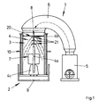
- Fig. 1 shows schematically a side view of an air cleaning device 1 for removing dust and / or dirt from an ambient air.
- the air cleaning device 1 comprises a housing 2, a cleaning device 3 with a filter device 4, a suction device 5, a conduit device 6 and an outlet device 7.
- the blower is fluidically connected to the housing 2 via a conduit means 6 formed as a flexible hose.
- the flexible hose extends from an outlet opening of the fan to an inlet opening located at the upper end side of the housing 2. In this case, the flexible hose terminates via an opening region with the inlet opening of the housing 2.
- the housing 2 comprises a cleaning device 3 which is fixed via a housing section and a filter device 4.
- the housing portion surrounds the filter device 4 and has a longitudinal axis, more precisely a vertical longitudinal axis.
- the filter device 4 in turn has a fluid supply pipe or riser 4a and a distributor nozzle device 20.
- the distributor nozzle device 20 is arranged at an upper end of the vertically arranged riser 4a, wherein the distributor nozzle device 20 preferably comprises a plurality of distributor nozzles 21, which are arranged in multiple stages, that is, one after the other.
- the exact design of the distributor nozzles 21 is in Fig. 2a and 2b shown in more detail and will be explained in connection with these drawings below.
- the last distributor nozzle 21 in the flow direction (of the medium) is secured against a vertical offset by a holding rod 8 integrated in the housing 2.
- the housing 2 has a bottom portion or a bottom. Together with the lower portion of the housing 2 thus a collecting container 9 is formed for a liquid medium.
- the liquid medium is conveyed via a feed pump 4c, which is connected to the riser 4a, through the riser 4a into the distributor nozzle device 20. From there, the medium exits through corresponding recesses and forms a curtain of atomized liquid medium. So that the distributor nozzle device 20 does not offset axially, the holding rod 8 in the housing 2 is formed directly above the distributor nozzle device 20.
- the dirty ambient air is passed through the suction device 5 through the conduit means 6 in the housing 2 by the cleaning device 4.
- the air to be cleaned passes through the curtain of atomized, liquid medium, whereby dirt particles are washed out. After the cleaning, the cleaned air is discharged through the outlet 7.
- the outlet 7 may also include a conduit means 6.
- Handles 10 are formed laterally on the housing 2 in order to simplify handling, in particular when transporting the air cleaning device 1.
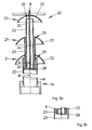
- FIG. 2a-b schematically show the distributor nozzle device 20 according to Fig. 1 in cross section, Fig. 2 a detail in detail, cut along the line AB according to Fig. 2a , laterally rotated by 90 ° Fig. 2a ,
- the distributor nozzle device 20 comprises three distributor nozzles 21, which each comprise an impact body 22 and a supply pipe line section 23.
- the baffles 22 are substantially plate-shaped or bell-shaped and have an impact surface 24 on their sides facing the respective feed pipe section 23.
- the baffle 24 is designed such that a liquid medium flowing out of an outlet opening 25 of the feed pipe section 23 onto the baffle 24 is deflected laterally.
- the baffle 24 is aligned inclined to a central axis M of the corresponding supply pipe section 23.
- the baffle 24 is approximately parabolic or bell-shaped.
- the distributor nozzles 21 are constructed in a similar way in principle and differ only slightly, for example in their dimensions.
- the supply pipe sections 23 are presently designed as circular cylindrical tubes, which accordingly have an outlet opening 25 with a circular flow cross-section.
- the material from which the supply pipe sections 23 may be a plastic, a metal, a metal alloy, stainless steel or the like, which may be coated, for example.
- the distributor nozzles 21 are arranged in multiple stages. That is, the distributor nozzles 21 are arranged in succession in the flow direction of the liquid medium, so that a plurality of medium curtains, preferably vertically offset from one another, can be produced.
- the supply pipe section 23 of a downstream distributor nozzle 21 protrudes into the supply pipe section 23 of the corresponding upstream distributor nozzle 21.
- the feed pipe sections 23 of the individual distributor nozzles 21 are correspondingly sized differently in the circumferential direction, in this case with a different diameter, wherein the external dimension of the downstream distributor nozzle 21 is smaller than the inside dimension of the upstream distributor nozzle 21.
- the difference between the external dimension of the downstream distributor nozzle 21 and the internal dimension the upstream distribution nozzle 21 is dimensioned such that a gap, in the present case an annular gap remains, through which the liquid medium can escape.
- the gap defines the resulting exit port for the liquid medium.
- the first distributor nozzle 21 in the flow direction that is, the first stage of the distributor nozzle device 20, is connected to the riser 4a.
- the corresponding connection regions of distributor nozzle 21 and riser 4a are formed so that they are sealingly connectable.
- the baffles 22 of the distribution nozzles 21 are respectively attached to the supply pipe portion 23 of the downstream distribution nozzle 21 except for the last distribution nozzle 21.
- the baffle 22 of the last distribution nozzle 21 in the flow direction, that is, the last stage of the distribution nozzle means 20 is fixed to a support rod 8 ,
- the support rod 8 protrudes with one end into the supply pipe section of the last distribution nozzle 21. With the other end, the support rod 8 is attached to a part of the air-cleaning device 1, preferably attached hinged.
- the supply pipe sections 23 of the distributing nozzles 21 are according to FIG Fig. 2a different lengths and open, with the exception of the supply pipe section 23 of the first distributor nozzle 21, in a common, designed as a holding web holder device 26.
- the respective ends of the supply pipe sections 23 are secured, so that an offset of the feed pipe sections 23 is prevented.
- the holding land is secured in the supply pipe section 23 of the first distribution nozzle 21.
- the supply pipe section 23 of the first distribution nozzle 21 is secured against misalignment via the connection with the riser 4a.
- the substantially as a hollow cylindrical, along the central or longitudinal axis M extending, present three distributor nozzles comprehensive distributor nozzle device 20 has distributed over its circumference openings or recesses 4b, through which the liquid medium is emitted.
- Fig. 2b shows a cross section of the distributor nozzle device 20, cut along the section line AB Fig. 2a , In this cross-section, the arrangement of the ends of the supply pipe sections 23 of the respective distributor nozzles 21 in the region of the holding device designed as a holding device 26 can be seen.
- the web has a parallelepiped shape and extends transversely through the supply pipe section 23 of the first distributor nozzle 21, wherein there is sufficient space for the liquid medium to flow past the holding web laterally.
- the holding web itself is connected to the support rod 8.
- Fig. 3a-d shows schematic representations of a housing 2.
- the housing is constructed substantially cylindrical and has a vertical longitudinal axis.
- the housing 2 is shown in a first side view.
- the housing 2 essentially has three areas: a bottom area 2a, a middle area 2b and an upper area 2c. These areas each have constant outer dimensions in the view, wherein the outer dimensions of the bottom portion 2 a to the upper portion 2 c are formed smaller, which increases the stability of the housing 2.
- Fig. 3b shows a longitudinal section through the housing 2, cut along the section line AA in Fig. 3a , Schematically here the riser 4a and the feed pump 4c is shown. Also clear is the double-tube structure of the housing with an inner tube 2d and an outer tube 2e. Laterally there is a blow-out, through which the purified air is discharged.
- the bottom portion 2a is formed as a collecting container 9, in which the liquid medium is collected and thus forms a reservoir.
- Fig. 3c shows the housing 2 in one of the in Fig. 2a Side view rotated by about 90 °.
- the blow-out opening formed in the central area 2b can clearly be seen for blowing out the cleaned air to the surroundings.
- Fig. 3d shows a longitudinal section of the housing 2 along the section line AA in Fig. 3c ,
- the bottom portion 2 a is formed as a collecting container 9.
- the feed pump 4c is fixed to a bottom of the housing 2 and fluidly connected to the riser 4a. Axially above the riser is integrated into the housing 2 holding rod 8 is formed, which prevents axial displacement of the distributor nozzle means (not shown) at the end of the riser 4a.
Abstract
Description
Die Erfindung betrifft eine Verteilerdüseneinrichtung für eine Filtereinrichtung einer Luft-Reinigungsvorrichtung, eine Filtereinrichtung für eine Luft-Reinigungsvorrichtung und eine Luft-Reinigungsvorrichtung gemäß dem Oberbegriff von Anspruch 1, Anspruch 20 bzw. Anspruch 21.The invention relates to a distributor nozzle device for a filter device of an air cleaning device, a filter device for an air cleaning device and an air cleaning device according to the preamble of claim 1,
Bei Sanierungs- oder Renovierungsarbeiten, aber auch bei Schreinerarbeiten, Schleifarbeiten u. dgl. fallen oft große Mengen an Staub und Schmutz an. Diese verteilen sich gleichmäßig im Raum, selbst durch geschlossene Türen hindurch. Lüften hilft meist wenig. In engen oder geschlossenen Räumen ist die Belastung oft besonders intensiv. Die Arbeiten müssen daher in stark verunreinigter Umgebungsluft durchgeführt werden. Die gesundheitliche Belastung ist sehr hoch. Die Verwendung von Atemschutzmasken ist nicht selten hinderlich bei der Ausführung der Arbeiten.For renovation or renovation work, but also carpentry, sanding u. Like. Often fall on large amounts of dust and dirt. These are distributed evenly in the room, even through closed doors. Airing usually helps little. In confined or confined spaces, the load is often particularly intense. The work must therefore be carried out in heavily polluted ambient air. The health burden is very high. The use of respirators is often a hindrance to the execution of the work.
Um dieser Beeinträchtigung zu begegnen, hat man Luft-Reinigungsvorrichtungen entwickelt. Diese saugen die staub- bzw. schmutzbeladene Umgebungsluft mit einem Gebläse an und leiten sie durch eine Filtereinrichtung oder mehrere Filtereinrichtungen hindurch. Die gereinigte Luft wird anschließend wieder in den Raum abgegeben oder nach außen geleitet. Finden mechanische Filtereinrichtungen Verwendung, so sind diese relativ großflächig auszubilden, um eine ausreichende Filterwirkung zu erzielen. Die Gebläseleistung muss entsprechend hoch gewählt werden, um einen ausreichenden Ansaugdruck zu erlangen. Darüber hinaus müssen die Filter regelmäßig gesäubert werden, was aufgrund der erneuten Staubfreisetzung nicht nur arbeitsaufwendig und belastend, sondern auf Dauer sehr teuer ist. Nach einiger Zeit müssen die Filtereinrichtungen sogar vollständig ausgetauscht werden.To counteract this impairment, air cleaning devices have been developed. These suck the dust or dirt-laden ambient air with a blower and pass it through a filter device or several filter devices. The purified air is then released back into the room or to the outside directed. If mechanical filter devices are used, they have to be of relatively large area in order to achieve a sufficient filtering effect. The blower power must be selected to be high enough to obtain sufficient suction pressure. In addition, the filter must be cleaned regularly, which is not only laborious and stressful due to the renewed release of dust, but in the long run very expensive. After some time, the filter devices must even be completely replaced.
Von Nachteil hierbei ist, dass das Gebläse den Luftstrom durch einen flächigen, relativ dünnen Wasserschleier hindurchdrückt, so dass dieser wie ein Vorhang stellenweise auseinander geblasen wird. Innerhalb des Luftstroms befindliche Staubpartikel werden daher nicht oder nur unzureichend befeuchtet und damit nicht ausgewaschen. Überdies ist das gesamte Gerät relativ groß und unhandlich. Es besteht aus insgesamt zwei sperrigen Teilen, nämlich einem quaderförmigen Gehäuseteil und einem rechteckigen Aufsatzturm mit den Luft-Ausblasöffnungen. Hinzu kommt die Wasserwanne als Reservoir und Sammelbehältnis für das Flüssigmedium. Alle Teile müssen einzeln transportiert und jedes Mal neu zusammengesetzt werden. Der Arbeits- und Montageaufwand ist entsprechend hoch. Der konstruktive Aufwand führt zu relativ hohen Herstellkosten.The disadvantage here is that the fan pushes the air flow through a flat, relatively thin water curtain, so that it is blown apart like a curtain in places. Dust particles within the air flow are therefore not or only insufficiently moistened and thus not washed out. Moreover, the entire device is relatively large and unwieldy. It consists of a total of two bulky parts, namely a cuboidal housing part and a rectangular tower tower with the air exhaust openings. In addition, the water tank as a reservoir and collection container for the liquid medium. All parts must be transported individually and reassembled each time. The labor and assembly costs are correspondingly high. The design effort leads to relatively high production costs.
Weiter ist aus der
Eine solche Vorrichtung ist zwar sehr handlich. Sie hat jedoch den Nachteil, dass sie hinsichtlich der Kapazität an zu reinigender Umgebungsluft begrenzt ist und nicht für große Mengen an zu reinigender Umluft ausgelegt ist.Such a device is very handy. However, it has the disadvantage that it is limited in terms of capacity of the ambient air to be cleaned and is not designed for large amounts of recirculated air to be cleaned.
Ziel der Erfindung ist es, diese und weitere Nachteile des Standes der Technik zu überwinden und eine flexibel ausgebildete Luft-Reinigungsvorrichtung zu schaffen, die hinsichtlich ihrer Funktionsweise gegenüber dem Stand der Technik verbessert ist und insbesondere für große Mengen an zu reinigender Luft ausgelegt ist. Angestrebt werden daher insbesondere eine verbesserte Verteilerdüseneinrichtung und eine verbesserte Filtereinrichtung. Diese sollen, ebenso wie die Luft-Reinigungsanlage, insgesamt einfach und kostengünstig aufgebaut sein. Die gesamte Anlage soll einfach zu handhaben sowie leicht de- und wieder montierbar sein.The aim of the invention is to overcome these and other disadvantages of the prior art and to provide a flexibly formed air cleaning device, which is improved in terms of their operation over the prior art and is designed especially for large amounts of air to be cleaned. Therefore, the aim is in particular an improved distributor nozzle device and an improved filter device. These should, as well as the air cleaning system, be overall simple and inexpensive. The entire system should be easy to handle and easy to dismantle and reassemble.
Diese Aufgabe wird von einer Verteilerdüseneinrichtung gemäß Anspruch 1, einer Filtereinrichtung gemäß Anspruch 20 und einer Luft-Reinigungsvorrichtung gemäß Anspruch 21 gelöst.This object is achieved by a distributor nozzle device according to claim 1, a filter device according to
Die technische Lehre der vorliegenden Erfindung sieht vor, dass bei einer Verteilerdüseneinrichtung für eine Filtereinrichtung einer Luft-Reinigungsvorrichtung, zum zerstäubten Verteilen eines flüssigen Mediums in einem aus der Umgebung angesaugten Luftstrom, vorgesehen ist, dass die Verteilerdüseneinrichtung mehrstufig mit mindestens zwei tellerdüsenartigen Verteilerdüsen ausgebildet ist. Die Mehrstufigkeit wird dabei durch eine nachgeschaltete Anordnung von mindesten zwei Verteilerdüsen bewirkt. Die Verteilerdüsen können gleich ausgebildet sein oder sich hinsichtlich Größe, Durchflussmenge, Ausstrahlmenge, Durchflussquerschnitt, Form, Aufbau, Druckverteilung, Durchflussgeschwindigkeit und dergleichen unterscheiden.The technical teaching of the present invention provides that, in the case of a distributor nozzle device for a filter device of an air cleaning device, for atomized distribution of a liquid medium in an air stream drawn in from the environment, it is provided that the distributor nozzle device is designed in multiple stages with at least two plate-nozzle-like distributor nozzles. The multistage is effected by a downstream arrangement of at least two distributor nozzles. The distributor nozzles can be of the same design or differ in terms of size, flow rate, discharge quantity, flow cross section, shape, structure, pressure distribution, flow rate and the like.
In einer Ausführungsform ist vorgesehen, dass die Verteilerdüsen jeweils einen Zufuhrrohrleitungsabschnitt mit einer Austrittsöffnung und einem der Austrittsöffnung beabstandet gegenüberliegenden, insbesondere teller-, kuppel- oder glockenförmigen Prallkörper aufweisen. Die Zufuhrrohrleitung kann als Rohrabschnitt mit einer Außenwandung und einem von der Außenwandung umgebenden Leitungsabschnitt ausgebildet sein. Dabei kann die Zufuhrrohrleitung einen beliebigen Querschnitt, genauer Durchflussquerschnitt, aufweisen, bevorzugt einen kreisförmigen Querschnitt.In one embodiment, it is provided that the distributor nozzles each have a supply pipe line section with an outlet opening and a spaced-apart, in particular plate-shaped, dome-shaped or bell-shaped impact body, spaced apart from the outlet opening. The supply pipe may be formed as a pipe section with an outer wall and a line section surrounding the outer wall. there For example, the supply pipe can have any cross-section, more specifically a flow cross-section, preferably a circular cross-section.
In einer weiteren Ausführungsform ist vorgesehen, dass der Prallkörper so ausgebildet, dass das durch die Austrittsöffnung auf den Prallkörper prallende flüssige Medium im Wesentlichen seitlich weg und/oder in einem Winkel nach unten und/oder nach oben gerichtet in dem Luftstrom von der Austrittsöffnung zerstäubt verteilt ist. Der Prallkörper fungiert somit als Umlenk- und/oder Zerstäubungskörper. Denn zum einen wird durch den Prallkörper das aufprallende flüssige Medium umgelenkt, bevorzugt umfänglich und/oder in einem Winkel im Bereich von >0° und < 180° zu einer Rohrleitungsachse, und zum anderen wird durch den Prallkörper das aufprallende flüssige Medium verteilt oder zerstäubt, um so eine Art Vorhang aus dem flüssigen Medium, umfassend Mediumtropfen, Mediumnebel und/oder Mediumstrahlen zu erzeugen. Hierzu weist der Prallkörper eine entsprechende Prallfläche oder entsprechende Prallflächen auf, auf welche das Medium aus der Austrittsöffnung kommend auftrifft. Die Prallflächen sind so angeordnet, dass diese eine Umlenkung und ein Verteilen des Mediumstrahls ermöglichen. Hierzu sind die Prallflächen bevorzugt geneigt zu der Rohrleitungsachse ausgerichtet.In a further embodiment, it is provided that the baffle body is designed such that the liquid medium bouncing through the outlet opening onto the baffle body is distributed substantially laterally away and / or at an angle directed downwards and / or upwards in the air flow from the outlet opening is. The baffle thus acts as a deflecting and / or atomizing body. For one thing, the baffle body deflects the impinging liquid medium, preferably circumferentially and / or at an angle in the range of> 0 ° and <180 ° to a pipeline axis, and on the other hand the baffle body distributes or atomizes the impacting liquid medium, so as to create a kind of curtain from the liquid medium comprising medium droplets, medium mist and / or medium jets. For this purpose, the impact body on a corresponding baffle or corresponding baffles on which impinges the medium coming from the outlet opening. The baffles are arranged so that they allow a deflection and a distribution of the medium beam. For this purpose, the baffles are preferably aligned inclined to the pipe axis.
In einem Ausführungsbeispiel ist der Prallkörper und damit auch die Prallfläche im Wesentlichen rotationssymmetrisch um eine Prallkörper-Mittelachse ausgebildet, um eine etwa rotationssymmetrisch gleichmäßige Verteilung des flüssigen Mediums zu bewirken. Auf diese Weise entsteht ein dichter Mediumvorhang und der Prallkörper ist leicht herzustellen.In one exemplary embodiment, the baffle body and thus also the baffle surface are formed substantially rotationally symmetrical about a baffle center axis in order to effect an approximately rotationally symmetrical uniform distribution of the liquid medium. In this way, a dense medium curtain is created and the impact body is easy to produce.
Bevorzugt ist die Prallkörper-Mittelachse koaxial und/oder in Verlängerung zu einer Zufuhrrohrleitungsabschnitt-Mittelachse ausgerichtet. Durch die symmetrische Anordnung lässt sich ein gleichmäßiger Mediumvorhang realisieren.Preferably, the bumper centerline is coaxially and / or aligned in extension to a feed tube section central axis. Due to the symmetrical arrangement, a uniform medium curtain can be realized.
In einem weiteren Ausführungsbeispiel ist der Zufuhrrohrleitungsabschnitt zumindest der Verteilerdüse der ersten Stufe mit einem Zufuhrrohr oder Steigrohr der Filtervorrichtung der Luft-Reinigungsvorrichtung verbindbar. Über das Zufuhrrohr wird das flüssige Medium von einer Quelle, bevorzugt druckbeaufschlagt, zu der ersten Verteilerdüse, betrachtet in Strömungsrichtung des Mediums, zugeführt. Der Zufuhrrohrleitungsabschnitt kann stoffschlüssig, formschlüssig und oder kraftschlüssig mit dem Zufuhrrohr, vorzugsweise abgedichtet, verbunden werden.In a further embodiment, the supply pipe section of at least the first stage distributor nozzle is connectable to a supply pipe or riser of the filter device of the air cleaner. Via the feed tube, the liquid medium from a source, preferably pressurized, to the first dispensing nozzle, as viewed in the direction of flow of the medium supplied. The supply pipe section can be materially, positively and / or non-positively connected to the supply pipe, preferably sealed.
Die Zufuhrrohrleitungsabschnitte der nachgeschalteten Verteilerdüsen sind bevorzugt jeweils gegenüber den Zufuhrrohrleitungsabschnitten der vorgeschalteten Verteilerdüsen in Umfangsrichtung kleiner ausgebildet. Auf diese Weise lassen sich die benachbarten Zufuhrrohrleitungsabschnitte ineinander stecken. Zudem lässt sich über eine geeignete Größenabmessung eine gleichmäßige und/oder geregelte Zufuhr des Mediums an die nachgeschalteten Verteilerdüsen realisieren.The feed pipe sections of the downstream distributor nozzles are preferred each formed opposite to the supply pipe sections of the upstream distributor nozzles in the circumferential direction smaller. In this way, the adjacent supply pipe sections can be plugged into each other. In addition, a uniform and / or regulated supply of the medium to the downstream distributor nozzles can be realized via a suitable size dimension.
Deshalb ragt in einer Ausführungsform jeweils der Zufuhrrohrleitungsabschnitt einer der ersten Verteilerdüse nachgeschalteten Verteilerdüsen jeweils in den Zufuhrrohrleitungsabschnitt der jeweils vorgeschalteten Verteilerdüse zumindest teilweise herein. Auf diese Weise lässt sich auf einfache Weise eine mehrstufige Verteilerdüseneinrichtung realisieren. Die Zufuhrrohrleitungsabschnitte sind dabei etwa nach Art eines Teleskops ineinander gesteckt, wobei zwischen den Zufuhrrohrleitungsabschnitten in Umfangsrichtung jeweils mindestens ein die Austrittsöffnung definierender Spalt ausgebildet ist.Therefore, in one embodiment, each of the supply pipe section of a distributor nozzle connected downstream of the first distributor nozzle projects at least partially into the supply pipe section of the respectively upstream distributor nozzle. In this way, a multi-stage distributor nozzle device can be realized in a simple manner. The supply pipe sections are inserted into one another in the manner of a telescope, wherein in each case at least one gap defining the outlet opening is formed between the supply pipe sections in the circumferential direction.
Entsprechend ist es vorgesehen, dass die ineinander hereinragenden Zufuhrrohrleitungsabschnitte so zueinander ausgerichtet sind, dass die entsprechende Austrittsöffnung des entsprechenden Zufuhrrohrleitungsabschnitts etwa spaltförmig oder ringförmig, das heißt mir einem Spiel in Umfangsrichtung, ausgebildet ist. Bei Zufuhrrohrleitungsabschnitten mit einem kreisrunden Querschnitt ist der Spalt kreisringförmig ausgebildet. Die Zufuhrrohrabschnitte sind vorzugsweise konzentrisch zueinander ausgerichtet. Bei anderen Geometrien ergeben sich entsprechende spaltförmige Öffnungen.Accordingly, it is provided that the mutually projecting supply pipe sections are aligned with each other so that the corresponding outlet opening of the corresponding feed pipe section is formed approximately in the form of a gap or a ring, that is to say a play in the circumferential direction. In feed pipe sections with a circular cross-section, the gap is annular. The feed pipe sections are preferably aligned concentrically with one another. With other geometries, corresponding gap-shaped openings result.
Um eine Rotationssymmetrie der Anordnung zu realisieren, sind die Mittelachsen der entsprechenden Zufuhrrohrleitungsabschnitte im Wesentlichen koaxial zueinander ausgebildet.In order to realize a rotational symmetry of the arrangement, the center axes of the corresponding feed pipe sections are formed substantially coaxially with each other.
In einer Ausführungsform ist vorgesehen, dass die Zufuhrrohrleitungsabschnitte mehrerer Verteilerdüsen mit einem Zufuhrrohr oder Steigrohr der Filtervorrichtung der Luft-Reinigungsvorrichtung verbindbar sind. Hierbei sind die einzelnen Zufuhrrohrleitungsabschnitte nicht ineinander angeordnet, sondern als separate Arme oder Verzweigung von dem (Haupt-)Zufuhrrohr abzweigend ausgebildet.In one embodiment, it is provided that the feed pipe sections of a plurality of distributor nozzles can be connected to a feed pipe or riser pipe of the filter device of the air cleaning device. Here, the individual feed pipe sections are not arranged inside each other, but branched off as separate arms or branching from the (main) supply pipe.
In einem Ausführungsbeispiel ist vorgesehen, dass die Zufuhrrohrleitungsabschnitte entlang ihrer Mittelachsen zumindest abschnittsweise einen konstanten Durchflussquerschnitt aufweisen. Somit können die Zufuhrrohrleitungsabschnitte etwa zylindrisch ausgebildet sein. Die Zufuhrrohrleitungsabschnitte könne auch abschnittsweise zylindrisch ausgebildet sein, zum Beispiel mit mehreren Abschnitten mit unterschiedlichen aber konstanten Durchmessern, also gestuft ausgebildet sein. Alternativ ist in einem anderen Ausführungsbeispiel vorgesehen, dass die Zufuhrrohrleitungsabschnitte entlang ihrer Mittelachsen einen veränderlichen Durchflussquerschnitt aufweisen. So können die Zufuhrrohrleitungsabschnitte etwa sich verjüngend oder sich verbreiternd ausgebildet sein, um zum Beispiel ein entsprechendes Druckverhältnis an der entsprechenden Austrittsöffnung bereitzustellen.In one exemplary embodiment, provision is made for the supply pipe sections to have a constant flow cross section at least in sections along their center axes. Thus, the supply pipe sections may be approximately cylindrical. The supply pipe sections could also be partially cylindrical, for example, with several sections with different but constant diameters, so be formed stepped. Alternatively, it is provided in another embodiment that the supply pipe sections have a variable flow cross-section along their central axes. Thus, the supply pipe sections may be approximately tapered or widening, for example, to provide a corresponding pressure ratio at the corresponding outlet opening.
Um eine stabile Anordnung zu realisieren, ist in einer Weiterbildung der Erfindung vorgesehen, dass die Zufuhrrohrleitungsabschnitte mittels entsprechender Halteeinrichtungen zueinander fixiert angeordnet sind. Auf diese Weise ist eine Relativbewegung der Zufuhrrohrleitungsabschnitte zueinander verhindert und ein einmal eingestelltes Druckverhältnis bzw. ein Spalt kann beibehalten werden.In order to realize a stable arrangement, it is provided in a development of the invention that the supply pipe sections are arranged fixed to one another by means of corresponding holding devices. In this way, a relative movement of the supply pipe sections to each other is prevented and a once set pressure ratio or a gap can be maintained.
Die Länge der Zufuhrrohrleitungsabschnitte von mindestens zwei Verteilerdüsen entlang ihrer Mittelachsen kann unterschiedlich ausgebildet sein. Hierdurch lässt sich ein zu erzeugender Mediumvorhang an entsprechende Umgebungsgeometrien anpassen.The length of the supply pipe sections of at least two distribution nozzles along their central axes may be formed differently. As a result, a medium curtain to be generated can be adapted to corresponding ambient geometries.
In einer Ausgestaltung der Erfindung ist vorgesehen, dass die ineinander hereinragenden Zufuhrrohrleitungsabschnitte alle mittels einer einzigen Halteeinrichtung zueinander fixiert sind. Das heißt, die Zufuhrrohrabschnitte beginnen oder münden im Wesentlichen in einer Ebene in der Halteeinrichtung und sind unterschiedlich lang ausgebildet. Die Halteeinrichtung ist bevorzugt als ein in einem Zufuhrrohrleitungsabschnitt der ersten Verteilerdüse angeordneter Steg ausgebildet, an welchem das flüssige Medium vorbeiströmen kann.In one embodiment of the invention, it is provided that the feed pipe sections protruding into one another are all fixed to one another by means of a single holding device. That is, the feed pipe sections begin or end substantially in a plane in the holding device and are of different lengths. The holding device is preferably designed as a web arranged in a feed pipe section of the first distributing nozzle and past which the liquid medium can flow.
Eine Ausführungsform der vorliegenden Erfindung sieht vor, dass der Prallkörper der letzten Stufe, das heißt der letzten Verteilerdüse in Strömungsrichtung, über eine Haltestange mit der Filtervorrichtung der Luft-Reinigungsvorrichtung verbindbar ist. Die Haltestange kann den Prallkörper durchdringen und in den entsprechenden Zufuhrrohrabschnitt hineinragen. Mindestens ein weiterer Prallkörper, bevorzugt alle weiteren Prallkörper, das heißt alle Prallkörper mit Ausnahme des Prallkörpers der letzten Stufe, sind bevorzugt an den Zufuhrrohrleitungsabschnitten der nachgeschalteten Verteilerdüsen angebracht. Auf diese Weise wird eine stabile Verteilerdüseneinrichtung gewährleistet.An embodiment of the present invention provides that the impact body of the last stage, that is, the last distributor nozzle in the flow direction, via a holding rod with the filter device of the air cleaning device is connectable. The support rod can penetrate the impact body and protrude into the corresponding feed pipe section. At least one further baffle body, preferably all other baffle bodies, that is to say all baffle bodies with the exception of the baffle body of the last stage, are preferably attached to the feed pipe sections of the downstream distributor nozzles. In this way, a stable distributor nozzle device is ensured.
Die technische Lehre der vorliegenden Erfindung sieht weiter vor, dass bei einer Filtereinrichtung für eine Luft-Reinigungsvorrichtung, mit einer erfindungsgemäßen Verteilerdüseneinrichtung zum zerstäubten Verteilen eines flüssigen Mediums in einem aus der Umgebung angesaugten Luftstrom vorgesehen ist, dass die Filtervorrichtung in eine Luft-Reinigungsvorrichtung einsetzbar ist.The technical teaching of the present invention further provides that in a filter device for an air cleaning device, with a distributor nozzle device according to the invention for the atomized distribution of a liquid medium in one of the Envisaged intake air flow is provided, that the filter device can be used in an air cleaning device.
Die Filtereinrichtung wird über eine Zuführleitung mit einem Fluid oder flüssigem Medium, bevorzugt mit Wasser, das druckbeaufschlagt ist, gespeist. Um das flüssige Medium zerstäubt in einem Luftstrom zu verteilen, weist die Filtereinrichtung eine Verteilerdüseneinrichtung auf. Die Verteilerdüseneinrichtung, welche das flüssige Medium in den Luftstrom zerstäubt verteilt, umfasst mehrere Verteilerdüsen. Jede Verteilerdüse weist einen Zufuhrrohrleitungsabschnitt auf, wobei an einem des Zufuhrrohrleitungsabschnitt abgewandten Ende der Verteilerdüse ein Prallkörper vorgesehen ist, der beabstandet zu dem Zufuhrrohrleitungsabschnitt angeordnet ist und so einen Spalt zum Austreten des flüssigen Mediums ausbildet. Zwischen der Wandung des Zufuhrrohrleitungsabschnitts und dem Prallkörper ist somit eine entsprechende Ausnehmungen ausgeformt, um das flüssige Medium durch diese in den Luftstrom einzubringen. Vorteilhaft ist eine schlitzförmige oder ringförmige Ausnehmungsform. Hierdurch lässt sich ein besonders geeigneter "Nebel" an flüssigem Medium in den Luftstrom bringen.The filter device is fed via a feed line with a fluid or liquid medium, preferably with water, which is pressurized. In order to disperse the liquid medium in an air stream, the filter device has a distributor nozzle device. The distributor nozzle device, which distributes the liquid medium atomized into the air flow, comprises a plurality of distributor nozzles. Each distributor nozzle has a feed pipe section, wherein at an end of the distributor nozzle facing away from the feed pipe section, an impact body is provided, which is arranged at a distance from the feed pipe section and thus forms a gap for the escape of the liquid medium. Between the wall of the feed pipe section and the baffle body thus a corresponding recesses is formed to introduce the liquid medium through this in the air flow. Advantageously, a slot-shaped or annular recess shape. As a result, a particularly suitable "fog" of liquid medium in the air flow can bring.
Die Verteilerdüseneinrichtung oder jeweils die Verteilerdüse weist eine Längsachse bzw. Mittelachse auf. Die Ausnehmungen der Verteilerdüsen zum Verteilen des flüssigen Mediums in dem Luftstrom sind zumindest teilweise als Spalte oder Umfangsöffnungen ausgebildet, die relativ zu der Achse konzentrisch verlaufende Schlitze oder Öffnungen, Aussparungen und dergleichen sind. Hierdurch lässt sich eine geeignete Einbringung des flüssigen Mediums in den Luftstrom realisieren. Der Verbrauch an flüssigem Medium in Bezug auf die Qualität der Reinigung ist somit optimiert. Zudem lassen sich die Ausnehmungen kostengünstig und auf einfache Weise herstellen.The distributor nozzle device or in each case the distributor nozzle has a longitudinal axis or central axis. The recesses of the distributor nozzles for distributing the liquid medium in the air flow are at least partially formed as gaps or circumferential openings, which are concentrically extending slots or openings, recesses and the like relative to the axis. This makes it possible to realize a suitable introduction of the liquid medium into the air stream. The consumption of liquid medium in terms of the quality of cleaning is thus optimized. In addition, the recesses can be produced inexpensively and easily.
Die technische Lehre der vorliegenden Erfindung sieht weiter vor, dass bei einer Luft-Reinigungsvorrichtung zum Entfernen von Staub und/oder Schmutz aus einer Umgebungsluft ein Gehäuse, in welchem eine Reinigungseinrichtung mit einer erfindungsgemäßen Filtereinrichtung aufgenommen ist, eine Ansaugeinrichtung, welche eine verschmutzte Umgebungsluft ansaugt, eine Leitungseinrichtung, welche sich von einer Ausgangsöffnung der Ansaugeinrichtung zu einer Einlassöffnung des Gehäuses erstreckt, und eine Auslasseinrichtung vorgesehen sind, wobei Umgebungsluft über die Leitungseinrichtung von der Ansaugeinrichtung in das Gehäuse durch die Reinigungseinrichtung geleitet wird und das durch die Reinigungseinrichtung durchströmte Fluid gereinigt über eine Ausblasöffnung der Auslasseinrichtung ausgeblasen wird.The technical teaching of the present invention further provides that in an air cleaning device for removing dust and / or dirt from an ambient air, a housing, in which a cleaning device is accommodated with a filter device according to the invention, a suction device, which sucks a polluted ambient air, a conduit means extending from an exit port of the aspirator to an inlet port of the housing and an outlet means are provided, ambient air being passed via the conduit means from the aspirator into the housing through the purifier and the fluid traversed by the purifier purified via an exhaust port the outlet is blown out.
Die Luft-Reinigungsvorrichtung ist somit modular aufgebaut, wobei die einzelnen Module über mindestens eine Leitungseinrichtung miteinander verbunden sind. Somit lassen sich auch Komponenten für große Mengen an zu reinigender Luft verwenden, ohne durch ein gemeinsames Gehäuse hinsichtlich der Größe begrenzt zu sein. Aufgrund der modularen Bauweise lässt sich die Vorrichtung auch einfach de- und wieder montieren. Es können stets neue Komponenten verwendet werden, so dass die Vorrichtung an die fortschreitende Entwicklung anpassbar ist.The air cleaning device is thus constructed modular, wherein the individual modules are connected to each other via at least one conduit means. Thus, components for large amounts of air to be cleaned can be used without being limited in size by a common housing. Due to the modular design, the device can also be easily dismantled and reassembled. New components can always be used so that the device is adaptable to the advancing development.
Es ist vorgesehen, dass die Reinigungseinrichtung durch die Filtereinrichtung und einen Gehäuseabschnitt mit einer von der angesaugten Luft durchströmbaren Durchgangsöffnung, welche zumindest einen Teil der Filtereinrichtung umgibt, festgelegt ist. Dabei stellt der Gehäuseabschnitt die äußere Begrenzung dar, durch welche der Luftstrom bewegt wird, und bildet somit einen Kanal für die zu reinigende Umgebungsluft. Die Filtereinrichtung ist so ausgelegt, dass das aus der Verteilerdüseneinrichtung in den Luftstrom eingebrachte flüssige Medium den gesamten Querschnitt in einer Draufsicht in Richtung einer Längsachse durch den Kanal einnimmt, so dass die gesamte Luft den durch das flüssige Medium erzeugten (mehrstufigen) Vorhang oder Nebel passieren muss.It is provided that the cleaning device is fixed by the filter device and a housing section with a through-opening through which the air sucked in, which surrounds at least part of the filter device. In this case, the housing section represents the outer boundary through which the air flow is moved, and thus forms a channel for the ambient air to be cleaned. The filter device is designed such that the liquid medium introduced from the distributor nozzle device into the air stream occupies the entire cross section in a plan view in the direction of a longitudinal axis through the channel, so that all the air passes through the (multi-level) curtain or mist produced by the liquid medium got to.
Weiter ist vorgesehen, dass das zerstäubte flüssige Medium über die Querschnittsfläche der Durchgangsöffnung des Gehäuseabschnitts der Reinigungsvorrichtung verteilbar ist. Zudem ist vorgesehen, dass die (Haupt-) Strömungsrichtung des Mediums im Wesentlichen mit der Strömungsrichtung des Luftstroms zusammenfällt. Dadurch wird zum einen verhindert, dass das flüssige Medium in das Gebläse eindringen kann. Zum anderen durchdringt das Medium den aus dem Gebläse kommenden Luftstrom nahezu vollständig, ohne diesen jedoch auseinander zu blasen, so dass selbst kleinste Staubpartikel auch im Inneren des Luftstroms von dem Medium erfasst und ausgespült werden.It is further provided that the atomized liquid medium can be distributed over the cross-sectional area of the passage opening of the housing section of the cleaning device. In addition, it is provided that the (main) flow direction of the medium substantially coincides with the flow direction of the air flow. This prevents on the one hand that the liquid medium can penetrate into the fan. On the other hand, the medium almost completely penetrates the air flow coming from the fan, without, however, blowing it apart, so that even the smallest dust particles are also caught and flushed out of the medium inside the air flow.
Hierzu trägt auch bei, dass das zerstäubte flüssige Medium einen sich längs und quer zu einer durch die Durchgangsöffnung verlaufenden Achse erstreckenden und/oder erweiternden Nebelstrom bildet. Dieser sorgt für einen intensiven Kontakt zwischen dem zerstäubten Medium und der zu reinigenden Umgebungsluft in einem relativ großen Volumen, wodurch stets ein hoher Reinigungsgrad gewährleistet ist.This is also helped by the fact that the atomized liquid medium forms a mist stream extending and / or expanding longitudinally and transversely to an axis extending through the passage opening. This ensures intensive contact between the atomized medium and the ambient air to be cleaned in a relatively large volume, whereby a high degree of purification is always ensured.
Der Luftstrom verläuft zumindest abschnittsweise koaxial zu der Längsachse des Gehäuseabschnitts, was die Prozessführung weiter vereinfacht und eine äußerst schlanke Bauweise der Luft-Reinigungsvorrichtung ermöglicht, deren Achse bevorzugt eine Vertikalachse ist.The air flow extends at least in sections coaxially with the longitudinal axis of the housing section, which further simplifies the process control and enables an extremely slim design of the air cleaning device whose axis is preferably a vertical axis.
Konstruktiv ist es günstig, dass die Ansaugeinrichtung ein Gebläse wie einen Lüfter umfasst, welcher separat zu dem Gehäuse aufstellbar ist. Hierdurch kann das Gehäuse schlank ausgelegt werden, ohne durch die Abmaße des Gebläses bestimmt zu werden. Das Gebläse lässt sich entsprechend der Anforderungen auswechseln und es lassen sich für große Mengen an zu reinigender Luft auch große Gebläse verwenden.Constructively, it is favorable that the suction device comprises a fan such as a fan, which is separately installable to the housing. As a result, the housing can be made slim, without being determined by the dimensions of the fan. The blower can be changed according to the requirements and large blowers can be used for large volumes of air to be cleaned.
Die Verbindung von Gebläse und Gehäuse erfolgt dabei über eine Leitungseinrichtung. Bevorzugt umfasst die Leitungseinrichtung mindestens einen flexiblen Schlauch mit einem Mündungsbereich, welcher in die Einlassöffnung mündet. Über den flexiblen Schlauch lassen sich die Hauptkomponenten wie Gebläse und Gehäuse einfach und flexibel verbinden. Über einen Mündungsbereich ist die Leitungseinrichtung einfach mit dem Gehäuse verbindbar.The connection of fan and housing takes place via a conduit device. The conduit device preferably comprises at least one flexible hose with an opening region which opens into the inlet opening. The flexible hose allows the main components such as fans and housings to be easily and flexibly connected. About a mouth region, the conduit means is simply connectable to the housing.
In einer Ausbildung weist das Gehäuse ein Außenrohr und zu diesem beabstandet ein Innenrohr auf, wobei der flexible Schlauch mit Mündungsbereich abschließend stirnseitig in das Innenrohr mündet. Dabei sind bevorzugt das Außenrohr und das Innenrohr koaxial zu der durch die Durchgangsöffnung verlaufenden Achse ausgebildet und über eine seitliche Überströmöffnung strömungsverbunden.In one embodiment, the housing has an outer tube and an inner tube spaced therefrom, wherein the flexible tube with the mouth region terminates at the end in the inner tube. In this case, the outer tube and the inner tube are preferably formed coaxially with the axis extending through the through-opening and flow-connected via a lateral overflow opening.
Die von dem flüssigen Medium gereinigte Luft kann dadurch ungehindert von dem Innenrohr in das Außenrohr und von dort nach außen (ins Freie) strömen.The cleaned of the liquid medium air can thereby freely flow from the inner tube into the outer tube and from there to the outside (to the outside).
Während die Ansaugöffnung des Gehäuses bevorzugt stirnseitig an dem Gehäuse ausgebildet ist, ist die Ausblasöffnung seitlich in dem Außenrohr ausgebildet. Damit wird eine unmittelbare Vermengung mit der zu reinigenden Luft vermieden. Durch die Überstromöffnung wird vermieden, dass das flüssige Medium direkt aus dem Gehäuse ausdringt, indem die Überströmöffnung und die Ausblasöffnung horizontal und/oder vertikal versetzt zueinander angeordnet sind, insbesondere gegenüberliegend und/oder höhenversetzt.While the intake opening of the housing is preferably formed on the front side of the housing, the exhaust opening is formed laterally in the outer tube. This avoids direct mixing with the air to be cleaned. The overflow opening prevents the liquid medium from being able to escape directly from the housing, in that the overflow opening and the blow-out opening are arranged horizontally and / or vertically offset from one another, in particular opposite and / or offset in height.
Eine Weiterbildung sieht vor, dass das Gehäuse im Wesentlichen einen runden oder eckigen Querschnitt aufweist. Das Außenrohr und das Innenrohr des Gehäuses sind im unteren Bereich über Stege und/oder einen Boden miteinander verbunden. Diese Ausbildung trägt zur kompakten und schlanken Bauweise der Vorrichtung sowie zu deren Stabilität bei.A further embodiment provides that the housing has a substantially round or angular cross-section. The outer tube and the inner tube of the housing are connected to each other in the lower region via webs and / or a bottom. This training contributes to the compact and slim design of the device as well as their stability.
Um eine einfache Handhabung zu realisieren, ist ein Sammelbehältnis zum Beinhalten und für die Zufuhr des flüssigen Mediums vom unteren Bereich des Innenrohrs gebildet. Insbesondere ist das Sammelbehältnis an einen gebäudeseitigen Abfluss anschließbar. Das verbrauchte flüssige Medium kann dabei mitsamt den ausgespülten Verunreinigungen direkt entsorgt werden.In order to realize a simple handling, a collecting container for containing and for the supply of the liquid medium from the lower region of the inner tube is formed. In particular, the collection container can be connected to a building-side outflow. The spent liquid medium can be disposed of directly together with the flushed impurities.
Alternativ sieht eine Maßnahme vor, dass das Sammelbehältnis eine separate Wanne ist, die den unteren Bereich des Gehäuses umschließt, und dass im unteren Rand des Außenrohrs, im unteren Rand des Innenrohrs sowie im Boden Durchströmöffnungen für das flüssige Medium eingebracht sind. Hierdurch ist ein Einsatz an Orten ohne Abflussmöglichkeit möglich. Dadurch kann das flüssige Medium ungehindert von dem Innenrohr aus in die Wanne strömen. Aufgrund der kompakten Abmessungen der Luft-Reinigungsvorrichtung ist hierbei keine spezielle Wanne mit besonderen Maßen erforderlich. Man kann vielmehr nahezu jede, gewöhnlich auf Baustellen vorhandene Wasserwanne verwenden.Alternatively, a measure provides that the collecting container is a separate tub, which encloses the lower portion of the housing, and that in the lower edge of the outer tube, in the lower edge of the inner tube and in the bottom flow openings are introduced for the liquid medium. As a result, use in places without drain possibility is possible. As a result, the liquid medium can flow unhindered from the inner tube into the tub. Due to the compact dimensions of the air cleaning device no special tub with special dimensions is required here. On the contrary, it is possible to use almost any water trough commonly found on construction sites.
Um ein Überlaufen an flüssigem Medium zu verhindern oder um ein Nachfüllen des flüssigen Mediums bei zu geringem Mediumpegel zu ermöglichen, ist in dem Sammelbehältnis eine Schwimmschaltereinrichtung vorgesehen ist. Durch die Schwimmerschalteinrichtung ist gewährleistet, dass die Vorrichtung vor Beschädigung zum Beispiel durch einen nicht optimalen Pegel an flüssigem Medium geschützt wird. Zudem lässt sich de Zuund Abfuhr des flüssigen Mediums so automatisieren und geeignet regeln.In order to prevent overflow of liquid medium or to allow refilling of the liquid medium at low medium level, a floating switch device is provided in the collecting container. By the float switching device ensures that the device is protected from damage, for example, by a non-optimal level of liquid medium. In addition, the supply and removal of the liquid medium can thus be automated and suitably regulated.
Um eine kompakte und handliche Bauweise zu realisieren, sieht eine weitere Maßnahme vor, dass die Filtereinrichtung koaxial zu der Achse ausgebildet ist. Das flüssige Medium kann nahezu von allen Seiten in den Luftstrom eindringen und die darin mitgeführten Verunreinigungen auswaschen, so dass der Wirkungsgrad der erfindungsgemäßen Vorrichtung trotz der kompakten Bauweise sehr hoch ist.To realize a compact and handy construction, provides a further measure that the filter device is formed coaxially to the axis. The liquid medium can penetrate almost from all sides in the air flow and wash out the impurities entrained therein, so that the efficiency of the device according to the invention is very high despite the compact design.
Um zu verhindern, dass sich Verteilerdüsen und/oder die Verteilerdüseneinrichtung in axialer Richtung versetzen oder sich von einer Zufuhrleitung oder dem Steigrohr löst, sieht eine Ausführungsform vor, dass die Verteilerdüseneinrichtung mittels einer Haltevorrichtung gegen axialen Versatz gesichert ist. Dadurch wird gerade bei hoher Druckbeaufschlagung des flüssigen Mediums eine sichere Funktionsweise der Verteilerdüseneinrichtung gewährleistet.In order to prevent distributor nozzles and / or the distributor nozzle device from displacing in the axial direction or becoming detached from a supply line or the riser pipe, an embodiment provides that the distributor nozzle device is secured against axial displacement by means of a holding device. As a result, a secure operation of the distributor nozzle device is ensured, especially at high pressure of the liquid medium.
Dabei ist die Haltevorrichtung bevorzugt in das Gehäuse integriert.In this case, the holding device is preferably integrated in the housing.
In einer weiteren Ausführungsform ist das Fluidzuführrohr als Steigrohr ausgebildet, welches an eine Druckleitung anschließbar ist. Insbesondere ist das Steigrohr an eine Förderpumpe angeschlossen, die das flüssige Medium aus dem Sammelbehältnis fördert. Dabei ist die Förderpumpe über dem Boden des Sammelbehältnisses fixiert.In a further embodiment, the fluid supply tube is formed as a riser, which is connectable to a pressure line. In particular, the riser is connected to a feed pump, which conveys the liquid medium from the collecting container. The delivery pump is fixed above the bottom of the collecting container.
Auf diese Weise kann das Medium in einem geschlossenen Kreislauf wieder verwendet werden, was sich weiter günstig auf die Betriebskosten auswirkt.In this way, the medium can be used again in a closed circuit, which further has a favorable effect on the operating costs.
Ein geeignetes und kostengünstig verfügbares flüssiges Medium ist Wasser. Deshalb ist es bevorzugt, dass das flüssige Medium Wasser, Leitungswasser und dergleichen ist.A suitable and inexpensive liquid medium is water. Therefore, it is preferable that the liquid medium is water, tap water and the like.
Es können jedoch auch andere Flüssigkeiten verwendet werden, die geeignet sind, Staub- und Schmutzpartikel aus einem Luftstrom auszuwaschen. Überdies können weitere Schadstoffe aus der Luft ausgefiltert werden. Das Wasser kann zudem auch geeignete Zusätze enthalten.However, other liquids can be used which are suitable for washing out dust and dirt particles from a stream of air. In addition, other pollutants can be filtered out of the air. The water may also contain suitable additives.
Für eine optimale Handhabung und einen einfachen Transport der Luft-Reinigungsvorrichtung ist vorgesehen, dass das Gehäuse seitlich mit wenigstens einem Handgriff versehen ist.For optimum handling and easy transport of the air cleaning device is provided that the housing is laterally provided with at least one handle.
Für einen einfachen Transport sind die Abmessungen des Gehäuses, insbesondere dessen Standfläche so bemessen, dass dieses auf einer Fläche, wie sie eine Europalette etwa festlegt, abstellbar oder unterbringbar ist. Dies ermöglicht einen einfacheren Transport auf einem geringen Raum.For ease of transport, the dimensions of the housing, in particular its footprint are dimensioned so that this on a surface, as it sets a Euro pallet about set off or can be accommodated. This allows easier transportation in a small space.
Um die Reinigungsvorrichtung nach dem Transport einfach montieren und nach der Verwendung wieder rasch demontieren zu können, ist vorgesehen, dass das Steigrohr über eine Steckverbindung von oben axial in die Pumpe einsetzbar ist. Auf diese Weise ist ein rascher Zusammenbau des Steigrohrs und der Pumpe möglich. Auf das Steigrohr wird dann noch die Verteilerdüseneinrichtung aufgesetzt, welche dann mit einer Haltevorrichtung gegen axialen Versatz gesichert wird. Der gesamte Aufbau kann ohne Werkzeug erfolgen, was die Handhabung weiter vereinfacht. Zudem können seitlich an dem Gehäuse Rolleinrichtung und dergleichen angebracht sein, welche zum Beispiel in einer gekippten Stellung des Gehäuses zum Einsatz kommen und einen Transport erleichtert.In order to easily mount the cleaning device after transport and disassemble quickly after use again, it is provided that the riser pipe can be inserted axially into the pump via a plug connection from above. In this way, a rapid assembly of the riser and the pump is possible. On the riser pipe then the distributor nozzle device is placed, which is then secured with a holding device against axial displacement. The entire structure can be done without tools, which further simplifies handling. In addition, laterally mounted on the housing rolling device and the like, which come for example in a tilted position of the housing used and facilitates transport.
Weitere Merkmale, Einzelheiten und Vorteile der Erfindung ergeben sich aus dem Wortlaut der Ansprüche sowie aus der folgenden Beschreibung von Ausführungsbeispielen anhand der Zeichnungen. Es zeigen:
- Fig. 1
- eine schematische Querschnitts-Seitenansicht einer Luft-Reinigungsvorrichtung mit einer Filtereinrichtung,
- Fig. 2a-b
- jeweils eine schematische Darstellung einer Verteilerdüseneinrichtung im Querschnitt, in
Fig. 2b einen Ausschnitt im Detail, geschnitten durch die Linie A-B gemäßFig. 2a , und - Fig. 3a-d
- schematische Darstellungen eines Gehäuses.
- Fig. 1
- a schematic cross-sectional side view of an air cleaning device with a filter device,
- Fig. 2a-b
- in each case a schematic representation of a distributor nozzle device in cross section, in
Fig. 2b a detail in detail, cut through the line AB according toFig. 2a , and - Fig. 3a-d
- schematic representations of a housing.
Die Ansaugrichtung 5, welche bevorzugt als Gebläse ausgebildet ist, ist getrennt von dem Gehäuse 2 angeordnet. In der dargestellten Ausführungsform ist das Gebläse über eine als flexibler Schlauch ausgebildete Leitungseinrichtung 6 mit dem Gehäuse 2 fluidisch verbunden. Der flexible Schlauch erstreckt sich von einer Ausgangsöffnung des Gebläses zu einer an der oberen Stirnseite des Gehäuses 2 befindlichen Eingangsöffnung. Dabei schließt der flexible Schlauch über einen Mündungsbereich mit der Eingangsöffnung des Gehäuses 2 ab.The
Das Gehäuse 2 umfasst eine Reinigungsvorrichtung 3, die über einen Gehäuseabschnitt und eine Filtereinrichtung 4 festgelegt ist. Der Gehäuseabschnitt umgibt die Filtereinrichtung 4 und weist eine Längsachse, genauer eine vertikale Längsachse auf. Die Filtereinrichtung 4 weist wiederum ein Fluidzuführrohr oder Steigrohr 4a und eine Verteilerdüseneinrichtung 20 auf. Die Verteilerdüseneinrichtung 20 ist an einem oberen Ende des vertikal angeordneten Steigrohrs 4a angeordnet, wobei die Verteilerdüseneinrichtung 20 bevorzugt mehrere Verteilerdüsen 21 umfasst, die mehrstufig, das heißt einander nachgeschaltet angeordnet sind. Die genaue Ausbildung der Verteilerdüsen 21 ist in
Das Gehäuse 2 weist einen Bodenbereich oder einen Boden auf. Zusammen mit dem unteren Bereich des Gehäuses 2 ist somit ein Sammelbehältnis 9 für ein flüssiges Medium ausgebildet. Das flüssige Medium wird über eine Förderpumpe 4c, welche mit dem Steigrohr 4a verbunden ist, durch das Steigrohr 4a in die Verteilerdüseneinrichtung 20 gefördert. Von da tritt das Medium durch entsprechende Ausnehmungen aus und bildet einen Vorhang aus zerstäubtem flüssigem Medium. Damit die Verteilerdüseneinrichtung 20 sich nicht axial versetzt, ist die Haltestange 8 in dem Gehäuse 2 direkt über der Verteilerdüseneinrichtung 20 ausgebildet.
Die verschmutzte Umgebungsluft wird über die Ansaugvorrichtung 5 durch die Leitungseinrichtung 6 in das Gehäuse 2 durch die Reinigungsvorrichtung 4 geführt. Dabei durchläuft die zu reinigende Luft den Vorhang aus zerstäubtem, flüssigem Medium, wobei Schmutzpartikel ausgewaschen werden. Nach der erfolgten Reinigung wird die gereinigte Luft durch die Auslasseinrichtung 7 abgegeben. Dabei kann die Auslasseinrichtung 7 ebenfalls eine Leitungseinrichtung 6 umfassen.The
The dirty ambient air is passed through the
Seitlich an dem Gehäuse 2 sind Handgriffe 10 ausgebildet, um die Handhabung insbesondere beim Transportieren der Luft-Reinigungsvorrichtung 1 zu vereinfachen.
Die Verteilerdüseneinrichtung 20 umfasst vorliegend drei Verteilerdüsen 21, die jeweils einen Prallkörper 22 und einen Zufuhrrohrleitungsabschnitt 23 umfassen. Die Prallkörper 22 sind im Wesentlichen tellerförmig oder glockenförmig ausgebildet und weisen an ihren dem jeweiligen Zufuhrrohrleitungsabschnitt 23 zugewandten Seiten eine Prallfläche 24 auf. Die Prallfläche 24 ist dabei so ausgebildet, dass ein aus einer Austrittsöffnung 25 des Zufuhrrohrleitungsabschnitts 23 auf die Prallfläche 24 ausströmendes flüssiges Medium seitlich abgelenkt wird. Hierzu ist die Prallfläche 24 geneigt zu einer Mittelachse M des entsprechenden Zufuhrrohrleitungsabschnitts 23 ausgerichtet. Vorliegend ist die Prallfläche 24 etwa parabelförmig oder glockenförmig ausgebildet. Die Verteilerdüsen 21 sind vom Grundsatz ähnlich aufgebaut und unterscheiden sich nur geringfügig, zum Beispiel in Ihren Abmaßen.In the present case, the
Die Zufuhrrohrleitungsabschnitte 23 sind vorliegend als kreiszylindrische Rohre ausgebildet, die entsprechend eine Austrittsöffnung 25 mit einem kreisförmigen Durchflussquerschnitt aufweisen. Das Material, aus welchem die Zufuhrrohrleitungsabschnitte 23 hergestellt sind, kann ein Kunststoff, ein Metall, eine Metalllegierung, Edelstahl oder dergleichen sein, welches zum Beispiel beschichtet sein kann.The
Die Verteilerdüsen 21 sind mehrstufig angeordnet. Das heißt, die Verteilerdüsen 21 sind in Strömungsrichtung des flüssigen Mediums nacheinander geschaltet angeordnet, so dass mehrere Mediumvorhänge, bevorzugt vertikal versetzt zueinander, erzeugbar sind. Hierzu ragt der Zufuhrrohrleitungsabschnitt 23 einer nachgeschalteten Verteilerdüse 21 in den Zufuhrrohrleitungsabschnitt 23 der entsprechend vorgeschalteten Verteilerdüse 21 hinein. Die Zufuhrrohrleitungsabschnitte 23 der einzelnen Verteilerdüsen 21 sind entsprechend in Umfangsrichtung unterschiedlich groß bemessen, vorliegend mit einem unterschiedlichen Durchmesser, wobei das Außenmaß der nachgeschalteten Verteilerdüse 21 kleiner ist, als das innenmaß der vorgeschalteten Verteilerdüse 21. Der Unterschied von Außenmaß der nachgeschalteten Verteilerdüse 21 und dem Innenmaß der vorgeschalteten Verteilerdüse 21 ist so bemessen, dass ein Spalt, vorliegend ein Ringspalt verbleibt, durch welchen das flüssige Medium austreten kann. Der Spalt definiert die resultierende Austrittsöffnung für das flüssige Medium. Die erste Verteilerdüse 21 in Strömungsrichtung, das heißt die erste Stufe der Verteilerdüseneinrichtung 20, ist mit dem Steigrohr 4a verbunden. Dabei sind die entsprechenden Verbindungsbereiche von Verteilerdüse 21 und Steigrohr 4a so ausgebildet, dass diese abdichtend verbindbar sind.The distributor nozzles 21 are arranged in multiple stages. That is, the
Die Prallkörper 22 der Verteilerdüsen 21 sind jeweils an dem Zufuhrrohrleitungsabschnitt 23 der nachgeschalteten Verteilerdüse 21 angebracht, mit Ausnahme der letzten Verteilerdüse 21. Der Prallkörper 22 der letzten Verteilerdüse 21 in Strömungsrichtung, das heißt der letzten Stufe der Verteilerdüseneinrichtung 20, ist an einer Haltestange 8 befestigt. Die Haltestange 8 ragt dabei mit einem Ende in den Zufuhrrohrleitungsabschnitt der letzten Verteilerdüse 21 hinein. Mit dem anderen Ende ist die Haltestange 8 an einem Teil der Luft-Reinigungsvorrichtung 1 befestigt, bevorzugt klappbar befestigt.The
Die Zufuhrrohrleitungsabschnitte 23 der Verteilerdüsen 21 sind gemäß
Die im Wesentlichen als hohlzylindrische, sich entlang der Mittel- oder Längsachse M erstreckende, vorliegend drei Verteilerdüsen umfassende Verteilerdüseneinrichtung 20 weist über Ihren Umfang verteilt Öffnungen oder Ausnehmungen 4b auf, durch welche das flüssige Medium ausgestrahlt wird.The substantially as a hollow cylindrical, along the central or longitudinal axis M extending, present three distributor nozzles comprehensive
Die Erfindung ist nicht auf eine der vorbeschriebenen Ausführungsformen beschränkt, sondern in vielfältiger Weise abwandelbar.The invention is not limited to one of the above-described embodiments, but can be modified in many ways.
Sämtliche aus den Ansprüchen, der Beschreibung und der Zeichnung hervorgehenden Merkmale und Vorteile, einschließlich konstruktiver Einzelheiten, räumlicher Anordnungen und Verfahrensschritten, können sowohl für sich als auch in den verschiedensten Kombinationen erfindungswesentlich sein.All of the claims, the description and the drawings resulting features and advantages, including design details, spatial arrangements and method steps may be essential to the invention both in itself and in various combinations.
- 11
- Luft-ReinigungsvorrichtungAir-cleaning device
- 22
- Gehäusecasing
- 2a2a
- Bodenbereichfloor area
- 2b2 B
- Mittelbereichthe central region
- 3c3c
- oberer Bereichupper area
- 33
- Reinigungsvorrichtungcleaning device
- 44
- Filtereinrichtungfiltering device
- 4a4a
- Steigrohrriser
- 4b4b
- Ausnehmung (Öffnung)Recess (opening)
- 4c4c
- Förderpumpefeed pump
- 55
- Ansaugeinrichtungsuction
- 66
- Leitungseinrichtungline device
- 77
- Auslasseinrichtungoutlet
- 88th
- HaltestangeHandrail
- 99
- Sammelbehältniscollecting container
- 1010
- Handgriffhandle
- 2020
- VerteilerdüseneinrichtungDistribution nozzle device
- 2121
- Verteilerdüsedistribution nozzle
- 2222
- Prallkörperbaffle
- 2323
- ZufuhrrohrleitungsabschnittSupply tubing section
- 2424
- Prallflächebaffle
- 2525
- Austrittsöffnungoutlet opening
- 2626
- Haltevorrichtungholder
- MM
- Mittelachsecentral axis
Claims (48)
wobei Umgebungsluft über die Leitungseinrichtung (6) von der Ansaugeinrichtung (5) in das Gehäuse (2) durch die Reinigungseinrichtung (3) geleitet wird und das durch die Reinigungseinrichtung (3) durchströmte Fluid gereinigt über eine Ausblasöffnung der Auslasseinrichtung (7) ausgeblasen wird.Air cleaning device (1) for removing dust and / or dirt from an ambient air with a housing (2), in which a cleaning device (3) with a filter device (4) according to claim 20 is accommodated, with a suction device (5), which sucks a polluted ambient air, with a conduit means (6) extending from an outlet opening of the suction means (5) to an inlet opening of the housing (2), and with an outlet means (7),
wherein ambient air via the conduit means (6) from the suction device (5) in the housing (2) is passed through the cleaning device (3) and the purified by the cleaning device (3) fluid is blown out through a blowout opening of the outlet device (7).
Applications Claiming Priority (1)
| Application Number | Priority Date | Filing Date | Title |
|---|---|---|---|
| DE202007009113U DE202007009113U1 (en) | 2007-06-28 | 2007-06-28 | Air-cleaning device |
Publications (1)
| Publication Number | Publication Date |
|---|---|
| EP2065082A1 true EP2065082A1 (en) | 2009-06-03 |
Family
ID=39986462
Family Applications (1)
| Application Number | Title | Priority Date | Filing Date |
|---|---|---|---|
| EP08010573A Withdrawn EP2065082A1 (en) | 2007-06-28 | 2008-06-11 | Air cleaning device |
Country Status (2)
| Country | Link |
|---|---|
| EP (1) | EP2065082A1 (en) |
| DE (1) | DE202007009113U1 (en) |
Cited By (3)
| Publication number | Priority date | Publication date | Assignee | Title |
|---|---|---|---|---|
| DE102015012783A1 (en) * | 2015-10-05 | 2017-04-06 | Dräger Safety AG & Co. KGaA | Conditioning module for tempering and humidifying a flowing gas |
| CN111550877A (en) * | 2020-05-11 | 2020-08-18 | 庄伙金 | Household air purification equipment |
| DE102020130767B3 (en) | 2020-11-20 | 2021-10-28 | Christopher Laubvogel | Housing for either an air cleaner or a suction device and system for cleaning air and vacuuming |
Citations (9)
| Publication number | Priority date | Publication date | Assignee | Title |
|---|---|---|---|---|
| NL60905C (en) * | ||||
| GB103488A (en) * | 1915-11-26 | 1900-01-01 | Ullern & Cie Soc | Improvements in or relating to Spraying Devices. |
| GB204796A (en) * | 1922-07-13 | 1923-10-11 | Albert Edwin Burton | Improvements in or relating to devices for spraying oil and other fluids |
| DE551537C (en) * | 1930-09-27 | 1932-06-01 | Otto & Co Gmbh Dr C | Sprinkler device for rack laundry |
| US2314754A (en) * | 1941-07-25 | 1943-03-23 | Hudson Engineering Corp | Spray head |
| JPS63151328A (en) * | 1986-12-13 | 1988-06-23 | Takeshi Mori | Air purifier |
| DE20302152U1 (en) | 2003-02-10 | 2003-05-08 | Staubfresser Gmbh | Mobile air filter for use in internal building renovation or construction has water curtain filter |
| WO2003070348A1 (en) * | 2002-02-21 | 2003-08-28 | Shell Internationale Research Maatschappij B.V. | Apparatus and method for treating a fluid |
| EP1506805A1 (en) | 2003-08-13 | 2005-02-16 | Klaus Kowalewski | Air cleaning device |
-
2007
- 2007-06-28 DE DE202007009113U patent/DE202007009113U1/en not_active Expired - Lifetime
-
2008
- 2008-06-11 EP EP08010573A patent/EP2065082A1/en not_active Withdrawn
Patent Citations (9)
| Publication number | Priority date | Publication date | Assignee | Title |
|---|---|---|---|---|
| NL60905C (en) * | ||||
| GB103488A (en) * | 1915-11-26 | 1900-01-01 | Ullern & Cie Soc | Improvements in or relating to Spraying Devices. |
| GB204796A (en) * | 1922-07-13 | 1923-10-11 | Albert Edwin Burton | Improvements in or relating to devices for spraying oil and other fluids |
| DE551537C (en) * | 1930-09-27 | 1932-06-01 | Otto & Co Gmbh Dr C | Sprinkler device for rack laundry |
| US2314754A (en) * | 1941-07-25 | 1943-03-23 | Hudson Engineering Corp | Spray head |
| JPS63151328A (en) * | 1986-12-13 | 1988-06-23 | Takeshi Mori | Air purifier |
| WO2003070348A1 (en) * | 2002-02-21 | 2003-08-28 | Shell Internationale Research Maatschappij B.V. | Apparatus and method for treating a fluid |
| DE20302152U1 (en) | 2003-02-10 | 2003-05-08 | Staubfresser Gmbh | Mobile air filter for use in internal building renovation or construction has water curtain filter |
| EP1506805A1 (en) | 2003-08-13 | 2005-02-16 | Klaus Kowalewski | Air cleaning device |
Cited By (4)
| Publication number | Priority date | Publication date | Assignee | Title |
|---|---|---|---|---|
| DE102015012783A1 (en) * | 2015-10-05 | 2017-04-06 | Dräger Safety AG & Co. KGaA | Conditioning module for tempering and humidifying a flowing gas |
| US10046286B2 (en) | 2015-10-05 | 2018-08-14 | Dräger Safety AG & Co. KGaA | Conditioning module for regulating the temperature of and humidifying a flowing gas |
| CN111550877A (en) * | 2020-05-11 | 2020-08-18 | 庄伙金 | Household air purification equipment |
| DE102020130767B3 (en) | 2020-11-20 | 2021-10-28 | Christopher Laubvogel | Housing for either an air cleaner or a suction device and system for cleaning air and vacuuming |
Also Published As
| Publication number | Publication date |
|---|---|
| DE202007009113U1 (en) | 2008-11-13 |
Similar Documents
| Publication | Publication Date | Title |
|---|---|---|
| EP2593600B1 (en) | Nozzle for cleaning a component loaded with lint | |
| DE102005055939B3 (en) | Nozzle crosspiece used in a device for producing a liquid jet comprises a pressure distribution chamber containing an impact body arranged over the length of a slot and not screwed to the crosspiece but inserted into it | |
| EP1506805B1 (en) | Air cleaning device | |
| EP3730022B1 (en) | Filter element | |
| WO2000010681A1 (en) | Method for cleaning candles in a candle filter | |
| EP1122338A2 (en) | Apparatus for spraying, pickling or rinsing liquids on metal objects | |
| DE1457299B2 (en) | DEVICE FOR THE REMOVAL OF PARTICLES FROM A CONTAMINATED GASEOUS MEDIUM | |
| DE19544074C2 (en) | Automatically working cleaning system for workpieces | |
| EP2065082A1 (en) | Air cleaning device | |
| DE19531421A1 (en) | Injector device for powder spray coating | |
| DE19637086A1 (en) | Automatically working cleaning system for workpieces | |
| EP4045169A1 (en) | Filter device and method for cleaning a filter element of a filter device | |
| AT522780A4 (en) | DEVICE FOR PURIFYING GAS | |
| EP1967296B1 (en) | Device for cleaning crates and base for this purpose | |
| EP0958977B1 (en) | Cleaning assembly for body of vehicles | |
| DE1948379C3 (en) | Device for purifying air | |
| EP0089466B1 (en) | Submerged aerator | |
| EP2827968B1 (en) | Filter element with cleaning unit for large volume flows | |
| DE2902461A1 (en) | DEVICE FOR PURIFYING GAS | |
| DE1671393C3 (en) | Wet washer | |
| DE202006013292U1 (en) | Air-cleaning device | |
| DE1778261C3 (en) | Device for drawing paint from the air in a paint spray booth | |
| EP0045939B1 (en) | Apparatus for the aeration of domestic and/or industrial sewage | |
| DE19516740C2 (en) | Vacuum toilet system | |
| DE2842651A1 (en) | Sewage aeration system - with air supply recess in channel bottom with flush fitting porous lid (NL 10.4.79) |
Legal Events
| Date | Code | Title | Description |
|---|---|---|---|
| PUAI | Public reference made under article 153(3) epc to a published international application that has entered the european phase |
Free format text: ORIGINAL CODE: 0009012 |
|
| AK | Designated contracting states |
Kind code of ref document: A1 Designated state(s): AT BE BG CH CY CZ DE DK EE ES FI FR GB GR HR HU IE IS IT LI LT LU LV MC MT NL NO PL PT RO SE SI SK TR |
|
| AX | Request for extension of the european patent |
Extension state: AL BA MK RS |
|
| AKX | Designation fees paid | ||
| STAA | Information on the status of an ep patent application or granted ep patent |
Free format text: STATUS: THE APPLICATION IS DEEMED TO BE WITHDRAWN |
|
| 18D | Application deemed to be withdrawn |
Effective date: 20090904 |
|
| REG | Reference to a national code |
Ref country code: DE Ref legal event code: 8566 |