EP2064979B1 - Electric suction head - Google Patents
Electric suction head Download PDFInfo
- Publication number
- EP2064979B1 EP2064979B1 EP07022070A EP07022070A EP2064979B1 EP 2064979 B1 EP2064979 B1 EP 2064979B1 EP 07022070 A EP07022070 A EP 07022070A EP 07022070 A EP07022070 A EP 07022070A EP 2064979 B1 EP2064979 B1 EP 2064979B1
- Authority
- EP
- European Patent Office
- Prior art keywords
- suction
- air outlet
- electric
- air
- housing
- Prior art date
- Legal status (The legal status is an assumption and is not a legal conclusion. Google has not performed a legal analysis and makes no representation as to the accuracy of the status listed.)
- Active
Links
- 238000001816 cooling Methods 0.000 claims description 36
- 238000004140 cleaning Methods 0.000 claims description 11
- 238000007789 sealing Methods 0.000 claims description 10
- 239000003570 air Substances 0.000 description 83
- 230000007423 decrease Effects 0.000 description 4
- 239000012080 ambient air Substances 0.000 description 2
- 230000000694 effects Effects 0.000 description 2
- 230000007257 malfunction Effects 0.000 description 2
- 238000013021 overheating Methods 0.000 description 2
- 239000002918 waste heat Substances 0.000 description 2
- 230000002745 absorbent Effects 0.000 description 1
- 239000002250 absorbent Substances 0.000 description 1
- 230000006978 adaptation Effects 0.000 description 1
- 238000010276 construction Methods 0.000 description 1
- 230000001419 dependent effect Effects 0.000 description 1
- 238000011161 development Methods 0.000 description 1
- 230000018109 developmental process Effects 0.000 description 1
- 238000006073 displacement reaction Methods 0.000 description 1
- 238000009434 installation Methods 0.000 description 1
- 238000005457 optimization Methods 0.000 description 1
Images


Classifications
-
- A—HUMAN NECESSITIES
- A47—FURNITURE; DOMESTIC ARTICLES OR APPLIANCES; COFFEE MILLS; SPICE MILLS; SUCTION CLEANERS IN GENERAL
- A47L—DOMESTIC WASHING OR CLEANING; SUCTION CLEANERS IN GENERAL
- A47L9/00—Details or accessories of suction cleaners, e.g. mechanical means for controlling the suction or for effecting pulsating action; Storing devices specially adapted to suction cleaners or parts thereof; Carrying-vehicles specially adapted for suction cleaners
- A47L9/02—Nozzles
- A47L9/04—Nozzles with driven brushes or agitators
Definitions
- the invention relates to a Elektrorosaugkopf for a vacuum cleaner with a housing, one of a disposed within the housing in an engine compartment electric motor cleaning device, a Saugmundkanten limited suction mouth on the underside of the housing and a suction port, wherein the engine compartment for the passage of air for cooling the electric motor has at least one air inlet opening for the entry of ambient air and at least one air outlet opening.
- the electric suction head can have an accumulator or an electrical connection for supplying power to the electric motor via a vacuum cleaner.
- the electric suction head can be connected without restriction via a suction pipe and a flexible hose or directly to a dust-housing, in the latter case, the weight of the vacuum cleaner on the Elektrorosaugkopf loads.
- the suction pipe or the sucker are connected to the suction port.
- the electric suction head is usually removable from the suction pipe or the vacuum cleaner housing and can be kept ready as an accessory. In particular equipped with an accumulator Elektrorosaugköpfe can be retrofitted as an accessory in a variety of commercial vacuum cleaners.
- Electric suction heads with the features described above are known in various embodiments from practice.
- the waste heat of the electric motor to prevent overheating and consequent malfunction must be dissipated.
- the engine's own fans are not sufficient in the normally cramped installation conditions to dissipate the waste heat.
- the electric motor has air inlet openings for the entry of ambient air and at least one air outlet opening.
- the air outlet openings open in the known versions in areas with a high negative pressure, for example, in a suction connection associated tilting joint or a suction channel within the housing.
- a corresponding embodiment is also from the JP 9 047 395 known.
- the suction-effective air volume and the pressure prevailing at the suction mouth vacuum is reduced by the required for cooling secondary air flow, the non-contributing to the suction side air flow is also referred to as incorrect or false air. Due to the required minimum amount of cooling air a good seal in the known versions of a Elektrorosaugkopfes is not possible.
- the invention has the object, in an electric vacuum head with the features described above to improve the suction and energy efficiency.
- the absorbent air amount can be maximized.
- the object is achieved in that the at least one air outlet opening is arranged on the underside of the housing such that the exiting during operation of the electric vacuum head from the air outlet opening cooling air passes through at least one of Saugmundkanten in the suction ,
- the air inlet openings of the engine compartment when sucking there is usually about the ambient pressure wherein in the region of the underside of the housing in which the air outlet opens, at least a slight negative pressure is created, whereby air is sucked from the environment and directed to the cooling of the engine and after leaving the air outlet openings together with a sucked at the bottom of the housing main air flow enters the suction mouth.
- the required cooling air is passed over at least one of the suction mouth edges and thus contributes to the total amount of air that is effective for suction.
- For the partial air flow of the cooling air takes place only in the flow direction before the Saugmundkanten a displacement of the suction.
- At the at least one air outlet opening at the bottom of the housing prevails in comparison to the known embodiments in which the air outlet opening is connected to a tilting joint, a suction channel or a roll chamber, a comparatively low negative pressure, which is why correspondingly large flow cross sections must be provided.
- this is readily possible due to the large area available at the bottom of the housing.
- a plurality of air outlet openings is provided on the underside of the housing in order, on the one hand, to achieve a sufficiently large flow cross section and, on the other hand, to prevent a malfunction in the event of clogging of an air outlet opening.
- a plurality of substantially identically formed air outlet openings arranged side by side. Basically, depending on the designs of the electric vacuum head and in particular the arrangement of the electric motor and air outlet openings seen in the working direction can be arranged in front of and behind the suction mouth, then passes over both Saugmundkanten each part of the entire cooling air into the suction.
- the distance of the air outlet opening to the associated suction mouth edge is less than 30 mm, preferably less than 15 mm.
- the at least one air outlet opening can expediently be arranged between the suction mouth and the sealing lip or the bristle strip.
- a further pressure drop is also observed at the sealing lip or the bristle strip, so that there is a defined under normal operating conditions negative pressure between the sealing lip or the bristle strip and the associated suction mouth.
- the channels, spaces and joints along the suction air flow between the suction mouth and the suction connection can be made particularly dense without impairing the cooling in order to minimize the occurrence of false air.
- Rigid and articulated connections between the parts of the Elektrorosaugkopfes may be provided for example with seals or flexible connecting hoses.
- the cooling air according to the invention contributes to the effective amount of air, a special high suction efficiency can be achieved even with a large demand for cooling air.
- the electric motor can easily be designed for a maximum power consumption under load of more than 50 W, preferably more than 100 W, particularly preferably more than 200 W.
- the at least one air outlet opening is arranged in a recess between preferably approximately perpendicular to the Saugmundkanten ribs.
- cooling ribs and / or a fan wheel can be arranged on the electric motor to support the cooling.
- the cross-section of the air inlet opening and / or the air outlet openings is designed to be adjustable, in order to enable an adaptation to a different demand for cooling air.
- the adjustment of the cross section can be done manually or temperature controlled, wherein at a shutdown of the electric motor, the at least one air outlet opening or the at least one air inlet opening can be closed. It is also possible to variably increase or decrease the flow cross sections as a function of different functional and power settings of the electric motor.
- an electrically or mechanically driven diaphragm can be provided.
- an automatic temperature control by means of a temperature sensor or a bimetal-controlled aperture can be done.
- a bypass is arranged on the engine compartment, which connects the engine compartment with a through-flow of the suction air channel or a through-flow of the suction chamber within the housing.
- the bypass can expediently be pressure-controlled and closed during normal suction operation. If the suction air stream, for example, on a very langflorigem carpet or a clogged suction mouth decreases sharply, under certain circumstances, a sufficient cooling of the electric motor can no longer be ensured.
- the negative pressure in the channels and chambers through which the suction air flows increases within the housing so that emergency cooling can be achieved by means of a bypass opening at a predetermined negative pressure.
- a cleaning roller arranged in a roller space which has spirally arranged lips or brush strips, is preferably provided as the cleaning device.
- the cleaning roller is usually aligned horizontally with its longitudinal axis perpendicular to the working direction of the Elektrorosaugkopfes.
- a plurality of vertically or obliquely arranged to the processing direction cleaning rollers or other type of cleaning devices can be provided.
- Fig. 1 shows an electrosuction head 1 according to the invention in a perspective view.
- the electric suction head 1 has a housing 2 in which an electric motor 4 for driving a cleaning device 5 designed as a brush roller is arranged in an engine compartment 3.
- the bristles of the brush roller pass through on the underside of the housing 2 extending over the width of the electrosuction head 1 and of a front Saugmundkante 6a and a rear Saugmundkante 6b limited suction mouth 7.
- Sealing lips 8a, 8b are each in the direction of movement in front of the front Saugmundkante 6a and behind the rear suction mouth edge 6b arranged.
- the electric suction head 1 has a suction connection 12 designed as a rotary tilting joint for connection to a suction pipe 13 or a vacuum cleaner housing.
- the power supply of the Elektrorosaugkopfes 1 can be done without restriction via an integrated into the Elektrorosaugkopf 1 voltage source or via a supply line from the vacuum cleaner.
- the electric suction head 1 is supported on its rear side by rollers 14.
- FIG. 2 which shows a bottom view of the Elektrorosaugkopfes 1, it can be seen, air outlet openings 15 of the engine compartment 3 are arranged on the underside of the housing 2 in the inflow region of the rear suction mouth edge 6b between the suction port 7 and the rear sealing lip 8b.
- air outlet openings 15 prevails in suction a certain negative pressure, so that cooling air is sucked through the air inlet openings 11 and the engine compartment 3 and after exiting the air outlet openings 15 via the rear Saugmundkante 6b enters the suction 7.
- the cooling air thus contributes to the suction-effective air flow, which flows into the suction mouth via the suction mouth edges 6a, 6b, whereby an optimization of the suction effect according to the invention is achieved.
- the air outlet openings 15 are arranged in a row next to one another at an equal distance from the rear suction mouth edge 6b in each case in a depression between ribs 16 running perpendicular to the rear suction mouth edge 6b.
- the electric motor 4 is typically designed for a power consumption under load of more than 50 W, preferably more than 100 W, particularly preferably more than 200 W.
- a flap opening in the direction of the roll chamber 17 in the direction of the roll chamber 17 is arranged as a bypass 19 on the engine compartment 3.
- the bypass 19 is closed during normal suction and opens when a predetermined negative pressure is exceeded, whereby an emergency cooling is achieved by entering from the engine compartment directly into the roll chamber emergency cooling flow N.
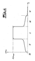
- Fig. 4 shows by way of example the prevailing at the bottom of the housing 2 in the longitudinal direction negative pressure Ap.
- a maximum negative pressure ⁇ p max. observed in relation to the ambient pressure.
- the negative pressure .DELTA.p decreases sharply, whereby the suction effect is decisively determined by the flow and the pressure distribution at the suction mouth edges 6a, 6b.
Landscapes
- Engineering & Computer Science (AREA)
- Mechanical Engineering (AREA)
- Nozzles For Electric Vacuum Cleaners (AREA)
Description
Die Erfindung betrifft einen Elektrosaugkopf für einen Staubsauger mit einem Gehäuse, einer von einem innerhalb des Gehäuses in einem Motorraum angeordneten Elektromotor antreibbaren Reinigungseinrichtung, einem von Saugmundkanten begrenzten Saugmund an der Unterseite des Gehäuses und einem Sauganschluss, wobei der Motorraum für den Durchtritt von Luft zur Kühlung des Elektromotors zumindest eine Lufteintrittsöffnung für den Eintritt von Umgebungsluft und zumindest eine Luftaustrittsöffnung aufweist.The invention relates to a Elektrorosaugkopf for a vacuum cleaner with a housing, one of a disposed within the housing in an engine compartment electric motor cleaning device, a Saugmundkanten limited suction mouth on the underside of the housing and a suction port, wherein the engine compartment for the passage of air for cooling the electric motor has at least one air inlet opening for the entry of ambient air and at least one air outlet opening.
Der Elektrosaugkopf kann zur Versorgung des Elektromotors einen Akkumulator oder auch einen elektrischen Anschluss zur Spannungsversorgung über einen Staubsauger aufweisen. Der Elektrosaugkopf kann ohne Einschränkung über ein Saugrohr und einen flexiblen Schlauch oder direkt an ein Staubsaugehäuse angeschlossen sein, wobei im letztgenannten Fall das Gewicht des Staubsaugers auf dem Elektrosaugkopf lastet. Das Saugrohr bzw. der Sauger werden mit dem Sauganschluss verbunden. Der Elektrosaugkopf ist üblicherweise von dem Saugrohr bzw. dem Staubsaugergehäuse abnehmbar und kann als Zubehör bereit gehalten werden. Insbesondere mit einem Akkumulator ausgerüstete Elektrosaugköpfe können als Zubehör bei unterschiedlichsten handelsüblichen Staubsaugern nachgerüstet werden.The electric suction head can have an accumulator or an electrical connection for supplying power to the electric motor via a vacuum cleaner. The electric suction head can be connected without restriction via a suction pipe and a flexible hose or directly to a dust-housing, in the latter case, the weight of the vacuum cleaner on the Elektrorosaugkopf loads. The suction pipe or the sucker are connected to the suction port. The electric suction head is usually removable from the suction pipe or the vacuum cleaner housing and can be kept ready as an accessory. In particular equipped with an accumulator Elektrorosaugköpfe can be retrofitted as an accessory in a variety of commercial vacuum cleaners.
Elektrosaugköpfe mit den eingangs beschriebenen Merkmalen sind in verschiedenen Ausführungen aus der Praxis bekannt. Bei den gattungsgemäßen Elektrosaugköpfen muss die Abwärme des Elektromotors zur Vermeidung einer Überhitzung und einer dadurch bedingten Fehlfunktion abgeführt werden. Insbesondere bei einem leistungsstarken Elektromotor, einem schlechten Wirkungsgrad des Elektromotors oder bei Spitzenbelastungen während des Reinigungsbetriebs sind motoreigene Lüfter bei den üblicherweise beengten Einbauverhältnissen nicht ausreichend, um die Abwärme abzuführen. Aus der Praxis ist es deshalb bekannt, den von einem Staubsauger erzeugten Saugunterdruck zu nutzen, um einen Nebenluftstrom zur Kühlung über den Motorraum des Elektromotors zu leiten. Der Elektromotor weist dabei Lufteintrittsöffnungen für den Eintritt von Umgebungsluft und zumindest eine Luftaustrittsöffnung auf. Als Lufteintritts- und Luftaustrittsöffnungen können dabei ohnehin vorhandene Undichtigkeiten oder speziell vorgesehene Kühlluftöffnungen vorgesehen sein, wobei die Luftaustrittsöffnungen bei den bekannten Ausführungen in Bereichen mit einem hohen Unterdruck, beispielsweise in ein dem Sauganschluss zugeordnetes Kippgelenk oder einen Saugkanal innerhalb des Gehäuses münden. Eine entsprechende Ausgestaltung ist auch aus der
Aus der Druckschrift
Bei den bekannten Ausführungen werden durch den zur Kühlung erforderlichen Nebenluftstrom die saugwirksame Luftmenge und der an dem Saugmund herrschende Unterdruck vermindert, wobei der nicht zur Saugwirkung beitragende Nebenluftstrom auch als Fehl- oder Falschluft bezeichnet wird. Aufgrund der erforderlichen Mindestkühlluftmenge ist eine gute Abdichtung bei den bekannten Ausführungen eines Elektrosaugkopfes nicht möglich.In the known embodiments, the suction-effective air volume and the pressure prevailing at the suction mouth vacuum is reduced by the required for cooling secondary air flow, the non-contributing to the suction side air flow is also referred to as incorrect or false air. Due to the required minimum amount of cooling air a good seal in the known versions of a Elektrorosaugkopfes is not possible.
Vor diesem Hintergrund liegt der Erfindung die Aufgabe zugrunde, bei einem Elektrosaugkopf mit den eingangs beschriebenen Merkmalen die Saug- und Energieeffizienz zu verbessern. Insbesondere soll unter Gewährleistung einer ausreichenden Kühlung des Elektromotors die saugwirksame Luftmenge maximiert werden.Against this background, the invention has the object, in an electric vacuum head with the features described above to improve the suction and energy efficiency. In particular, while ensuring a sufficient cooling of the electric motor, the absorbent air amount can be maximized.
Ausgehend von einem Elektrosaugkopf mit den eingangs beschriebenen Merkmalen wird die Aufgabe erfindungsgemäß dadurch gelöst, dass die zumindest eine Luftaustrittsöffnung an der Unterseite des Gehäuses derart angeordnet ist, dass die beim Betrieb des Elektrosaugkopfes aus der Luftaustrittsöffnung austretende Kühlluft über zumindest eine der Saugmundkanten in den Saugmund gelangt. An den Lufteintrittsöffnungen des Motorraums herrscht beim Saugen üblicherweise etwa der Umgebungsdruck, wobei in dem Bereich der Unterseite des Gehäuses, in dem die Luftaustrittsöffnung mündet, zumindest ein leichter Unterdruck entsteht, wodurch Luft aus der Umgebung angesaugt und zur Kühlung über den Motor geleitet wird und nach dem Verlassen der Luftaustrittsöffnungen gemeinsam mit einem an der Unterseite des Gehäuses angesaugten Hauptluftstrom in den Saugmund gelangt. Erfindungsgemäß wird die erforderliche Kühlluft über zumindest eine der Saugmundkanten geleitet und trägt so zu der gesamten saugwirksamen Luftmenge bei. Für den Teilluftstrom der Kühlluft erfolgt lediglich in Strömungsrichtung gesehen vor den Saugmundkanten eine Verlagerung der Ansaugung. An der zumindest einen Luftaustrittsöffnung an der Unterseite des Gehäuses herrscht im Vergleich zu den bekannten Ausführungen, bei dem die Luftaustrittsöffnung an ein Kippgelenk, ein Saugkanal oder einen Walzenraum angeschlossen ist, ein vergleichsweise geringer Unterdruck, weshalb auch entsprechend große Strömungsquerschnitte vorgesehen sein müssen. Dies ist jedoch aufgrund der großen an der Unterseite des Gehäuses zur Verfügung stehenden Fläche ohne weiteres möglich.Starting from a Elektrorosaugkopf with the features described above, the object is achieved in that the at least one air outlet opening is arranged on the underside of the housing such that the exiting during operation of the electric vacuum head from the air outlet opening cooling air passes through at least one of Saugmundkanten in the suction , At the air inlet openings of the engine compartment when sucking there is usually about the ambient pressure, wherein in the region of the underside of the housing in which the air outlet opens, at least a slight negative pressure is created, whereby air is sucked from the environment and directed to the cooling of the engine and after leaving the air outlet openings together with a sucked at the bottom of the housing main air flow enters the suction mouth. According to the invention, the required cooling air is passed over at least one of the suction mouth edges and thus contributes to the total amount of air that is effective for suction. For the partial air flow of the cooling air takes place only in the flow direction before the Saugmundkanten a displacement of the suction. At the at least one air outlet opening at the bottom of the housing prevails in comparison to the known embodiments in which the air outlet opening is connected to a tilting joint, a suction channel or a roll chamber, a comparatively low negative pressure, which is why correspondingly large flow cross sections must be provided. However, this is readily possible due to the large area available at the bottom of the housing.
Vorzugsweise ist an der Unterseite des Gehäuses eine Vielzahl von Luftaustrittsöffnungen vorgesehen, um einerseits einen ausreichend großen Strömungsquerschnitt zu erreichen und andererseits bei einem Verstopfen einer Luftaustrittsöffnung eine Fehlfunktion zu vermeiden. Vorzugsweise sind mehrere im Wesentlichen gleich ausgebildete Luftaustrittsöffnungen nebeneinander angeordnet. Grundsätzlich können abhängig von der Konstruktionen des Elektrosaugkopfes und insbesondere der Anordnung des Elektromotors auch Luftaustrittsöffnungen in Arbeitsrichtung gesehen vor und hinter dem Saugmund angeordnet sein, wobei dann über beide Saugmundkanten jeweils ein Teil der gesamten Kühlluft in den Saugmund gelangt.Preferably, a plurality of air outlet openings is provided on the underside of the housing in order, on the one hand, to achieve a sufficiently large flow cross section and, on the other hand, to prevent a malfunction in the event of clogging of an air outlet opening. Preferably a plurality of substantially identically formed air outlet openings arranged side by side. Basically, depending on the designs of the electric vacuum head and in particular the arrangement of the electric motor and air outlet openings seen in the working direction can be arranged in front of and behind the suction mouth, then passes over both Saugmundkanten each part of the entire cooling air into the suction.
Um an der zumindest einen Luftaustrittsöffnung einen ausreichenden Unterdruck zur Förderung der Kühlluft zu gewährleisten ist diese vorzugsweise in einem Anströmbereich einer der Saugmundkanten angeordnet. Bei einer üblichen Konstruktion des Elektrosaugkopfes beträgt der Abstand der Luftaustrittsöffnung zu der zugeordneten Saugmundkante weniger als 30 mm, vorzugsweise weniger als 15 mm.In order to ensure a sufficient negative pressure for conveying the cooling air at the at least one air outlet opening, it is preferably arranged in an inflow region of one of the suction mouth edges. In a conventional construction of the electric suction head, the distance of the air outlet opening to the associated suction mouth edge is less than 30 mm, preferably less than 15 mm.
Wenn an der Unterseite des Gehäuses eine Dichtlippe, Borstenleiste oder dergleichen vorgesehen ist, kann die zumindest eine Luftaustrittsöffnung zweckmäßigerweise zwischen dem Saugmund und der Dichtlippe bzw. der Borstenleiste angeordnet werden. Zusätzlich zu der Druckdifferenz über die Saugmundkanten wird auch an der Dichtlippe bzw. der Borstenleiste ein weiterer Druckabfall beobachtet, so dass zwischen der Dichtlippe bzw. der Borstenleiste und der zugeordneten Saugmundkante ein bei üblichen Betriebsbedingungen definierter Unterdruck herrscht.If a sealing lip, bristle strip or the like is provided on the underside of the housing, the at least one air outlet opening can expediently be arranged between the suction mouth and the sealing lip or the bristle strip. In addition to the pressure difference across the suction mouth edges, a further pressure drop is also observed at the sealing lip or the bristle strip, so that there is a defined under normal operating conditions negative pressure between the sealing lip or the bristle strip and the associated suction mouth.
Durch die erfindungsgemäße Ausgestaltung können die Kanäle, Räume und Gelenke entlang des Saugluftstroms zwischen dem Saugmund und dem Sauganschluss ohne Beeinträchtigung der Kühlung besonders dicht ausgeführt werden, um das Auftreten von Falschluft zu minimieren. Starre und gelenkige Verbindungen zwischen den Teilen des Elektrosaugkopfes können beispielsweise mit Dichtungen oder flexiblen Verbindungsschläuchen versehen sein.As a result of the configuration according to the invention, the channels, spaces and joints along the suction air flow between the suction mouth and the suction connection can be made particularly dense without impairing the cooling in order to minimize the occurrence of false air. Rigid and articulated connections between the parts of the Elektrorosaugkopfes may be provided for example with seals or flexible connecting hoses.
Da die Kühlluft erfindungsgemäß zu der saugwirksamen Luftmenge beiträgt, kann auch bei einem großen Bedarf an Kühlluft eine besonderes hohe Saugeffizienz erreicht werden. So kann der Elektromotor ohne Weiteres für eine maximale Leistungsaufnahme unter Last von mehr als 50 W, vorzugsweise mehr als 100 W, besonders bevorzugt mehr als 200 W ausgelegt sein.Since the cooling air according to the invention contributes to the effective amount of air, a special high suction efficiency can be achieved even with a large demand for cooling air. Thus, the electric motor can easily be designed for a maximum power consumption under load of more than 50 W, preferably more than 100 W, particularly preferably more than 200 W.
Im Rahmen einer bevorzugten Ausgestaltung der Erfindung ist die zumindest eine Luftaustrittsöffnung in einer Vertiefung zwischen vorzugsweise etwa senkrecht zu den Saugmundkanten verlaufenden Rippen angeordnet. Durch die in etwa in Strömungsrichtung verlaufenden Rippen und die zurückversetzte Anordnung der Luftaustrittsöffnung können auch bei einem langflorigem Bodenbelag ein Zusetzen der Luftaustrittsöffnung verhindert und ein ausreichender Luftstrom gewährleistet werden.In a preferred embodiment of the invention, the at least one air outlet opening is arranged in a recess between preferably approximately perpendicular to the Saugmundkanten ribs. By extending approximately in the direction of flow ribs and the set-back arrangement of the air outlet opening clogging of the air outlet opening can be prevented and a sufficient air flow can be ensured even in a long pile floor covering.
Ausgehend von der beschriebenen Ausgestaltung eines Elektrosaugkopfes ergeben sich eine Vielzahl von bevorzugten Weiterbildungen. An dem Elektromotor können beispielsweise zur Unterstützung der Kühlung Kühlrippen und/oder ein Lüfterrad angeordnet sein. Des Weiteren kann vorgesehen sein, den Querschnitt der Lufteintrittsöffnung und/oder der Luftaustrittsöffnungen verstellbar auszugestalten, um eine Anpassung an einen unterschiedlichen Bedarf von Kühlluft zu ermöglich. Die Verstellung des Querschnittes kann dabei manuell oder temperaturgesteuert erfolgen, wobei bei einer Abschaltung des Elektromotors auch die zumindest eine Luftaustrittsöffnung oder die zumindest eine Lufteintrittsöffnung verschlossen werden kann. Es ist auch möglich, die Strömungsquerschnitte in Abhängigkeit von unterschiedlichen Funktions- und Leistungsstellungen des Elektromotors variabel zu vergrößern oder verringern. Zur Querschnittsänderung kann dabei eine elektrisch oder mechanisch angetriebene Blende vorgesehen sein. Darüber hinaus kann auch eine automatische Temperatursteuerung mittels eines Temperatursensors oder einer Bimetallgesteuerten Blende erfolgen.Starting from the described embodiment of a Elektrorosaugkopfes arise a variety of preferred developments. For example, cooling ribs and / or a fan wheel can be arranged on the electric motor to support the cooling. Furthermore, it can be provided that the cross-section of the air inlet opening and / or the air outlet openings is designed to be adjustable, in order to enable an adaptation to a different demand for cooling air. The adjustment of the cross section can be done manually or temperature controlled, wherein at a shutdown of the electric motor, the at least one air outlet opening or the at least one air inlet opening can be closed. It is also possible to variably increase or decrease the flow cross sections as a function of different functional and power settings of the electric motor. To change the cross section, an electrically or mechanically driven diaphragm can be provided. In addition, an automatic temperature control by means of a temperature sensor or a bimetal-controlled aperture can be done.
Im Rahmen einer weiteren Ausgestaltung der Erfindung ist vorgesehen, dass an dem Motorraum ein Bypass angeordnet ist, der den Motorraum mit einem von der Saugluft durchströmten Kanal oder einer von der Saugluft durchströmten Kammer innerhalb des Gehäuses verbindet. Durch den Bypass kann ein zusätzlicher Luftstrom bereit gestellt werden, der bei einer übermäßigen Verringerung des aus der zumindest einen Luftaustrittsöffnung strömenden Kühlluftstroms eine Notkühlung ermöglicht. Der Bypass kann dabei zweckmäßigerweise druckgesteuert und beim normalen Saugbetrieb geschlossen sein. Wenn der Saugluftstrom beispielsweise auf einem sehr langflorigem Teppich oder bei einem verstopften Saugmund stark abnimmt, kann unter Umständen eine ausreichende Kühlung des Elektromotors nicht mehr sichergestellt werden. Gleichzeit nimmt der Unterdruck in den von der Saugluft durchströmten Kanälen und Kammern innerhalb des Gehäuses zu, so dass durch einen bei einem vorgegebenen Unterdruck öffnenden Bypass eine Notkühlung erreicht werden kann.As part of a further embodiment of the invention, it is provided that a bypass is arranged on the engine compartment, which connects the engine compartment with a through-flow of the suction air channel or a through-flow of the suction chamber within the housing. By the bypass, an additional air flow can be provided, which allows for an excessive reduction of the flowing from the at least one air outlet opening cooling air flow emergency cooling. The bypass can expediently be pressure-controlled and closed during normal suction operation. If the suction air stream, for example, on a very langflorigem carpet or a clogged suction mouth decreases sharply, under certain circumstances, a sufficient cooling of the electric motor can no longer be ensured. At the same time, the negative pressure in the channels and chambers through which the suction air flows increases within the housing so that emergency cooling can be achieved by means of a bypass opening at a predetermined negative pressure.
Als Reinigungseinrichtung ist im Rahmen der Erfindung vorzugsweise eine in einem Walzenraum angeordnete Reinigungswalze vorgesehen, die spiralförmig angeordnete Lippen oder Bürstenstreifen aufweist. Die Reinigungswalze ist dabei üblicherweise mit ihrer Längsachse senkrecht zur Arbeitsrichtung des Elektrosaugkopfes horizontal ausgerichtet. Ohne Einschränkung können jedoch im Rahmen der Erfindung auch mehrere senkrecht oder schräg zur Bearbeitungsrichtung angeordnete Reinigungswalzen oder anders artige Reinigungseinrichtungen vorgesehen sein.In the context of the invention, a cleaning roller arranged in a roller space, which has spirally arranged lips or brush strips, is preferably provided as the cleaning device. The cleaning roller is usually aligned horizontally with its longitudinal axis perpendicular to the working direction of the Elektrorosaugkopfes. Without limitation, however, can be provided within the scope of the invention, a plurality of vertically or obliquely arranged to the processing direction cleaning rollers or other type of cleaning devices.
Die Erfindung wird nachfolgend anhand einer lediglich ein Ausführungsbeispiel darstellenden Zeichnung erläutert. Es zeigen schematisch:
- Fig. 1
- eine perspektivische Ansicht eines erfindungsgemäßen Elektrosaugkopfes,
- Fig. 2
- der Elektrosaugkopf gemäß
Fig. 1 in einer Ansicht von unten - Fig. 3
- ein Vertikalschnitt entlang der Linie A-A der
Fig. 2 , - Fig. 4
- der qualitative Verlauf des an der Unterseite des Gehäuses entlang der Linie A-A herrschenden Unterdrucks Δp.
- Fig. 1
- a perspective view of a Elektrorosaugkopfes invention,
- Fig. 2
- the electric suction head according to
Fig. 1 in a view from below - Fig. 3
- a vertical section along the line AA of
Fig. 2 . - Fig. 4
- the qualitative course of the prevailing at the bottom of the housing along the line AA negative pressure Ap.
Wie der
Die Luftaustrittsöffnungen 15 sind in einer Reihe nebeneinander in einem gleichen Abstand zu der hinteren Saugmundkante 6b jeweils in einer Vertiefung zwischen senkrecht zu der hinteren Saugmundkante 6b verlaufenden Rippen 16 angeordnet. Durch die Rippen 16 und die zurückversetzte Anordnung der Luftaustrittsöffnungen 15 kann die Gefahr eines Zusetzens der Luftaustrittsöffnungen 15 auf einem Teppichboden reduziert werden.The
Im Gegensatz zu dem aus dem Stand der Technik bekannten Ausführungen kann auch bei einer großen Leistungsaufnahme des Elektromotors eine sehr hohe Dichtheit des Elektrosaugkopfes 1 erreicht werden. Der Elektromotor 4 ist dabei typischerweise für eine Leistungsaufnahme unter Last von mehr als 50 W, vorzugsweise mehr als 100 W, besonders bevorzugt mehr als 200 W ausgelegt.In contrast to the embodiments known from the prior art, a very high tightness of the
Der
Claims (9)
- Electric suction head for a vacuum cleaner comprising a housing (2), a cleaning device (5) able to be driven by an electric motor (4), arranged inside the housing (2) in a motor chamber (3), a suction orifice (7), delimited by suction orifice edges (6a, 6b) on the underside of the housing (2) and a suction connection (12), wherein the motor chamber (3) has at least one air inlet opening (11) and at least one air outlet opening (15) for the passage of air for cooling the electric motor (4), characterized in that the air outlet opening (15) is arranged on the underside of the housing (2) such that the cooling air, emerging out of the air outlet opening (15) when the electric suction head (1) is in operation, arrives into the suction orifice (7) via at least one of the suction orifice edges.
- Electric suction head according to Claim 1, characterized by a plurality of air outlet openings (15) on the underside of the housing (2).
- Electric suction head according to Claim 1 or 2, characterized in that the at least one air outlet opening (15) is arranged in a depression between ribs (16) running preferably approximately perpendicularly to the suction orifice edges (6a, 6b).
- Electric suction head according to any of Claims 1 to 3, characterized in that the cleaning device (5) is constructed as a cleaning roller arranged in a roller chamber (17).
- Electric suction head according to any of Claims 1 to 4, characterized in that the air outlet opening (15) is arranged in an approach flow region of one of the suction orifice edges (6a, 6b).
- Electric suction head according to any of Claims 1 to 5, characterized in that on the underside of the housing (2) a sealing lip (8a, 8b) or a bristle strip is provided, with the air outlet opening being arranged between the suction orifice (7) and the sealing lip (8a, 8b) or the bristle strip.
- Electric suction head according to any of Claims 1 to 6, characterized in that the electric motor (4) is designed for a maximum power consumption under load of more than 50 W (Watt), preferably more than 100 W, particularly preferably more than 200 W.
- Electric suction head according to any of Claims 1 to 7, characterized in that the cross-section of the air inlet opening (11) and/or of the air outlet opening (15) is adjustable.
- Electric suction head according to any of Claims 1 to 8, characterized in that a bypass (19) is arranged on the motor chamber (3), which connects the motor chamber (3) with a duct which has the suction air flowing through it, or with a chamber which has the suction air flowing through it, inside the housing (2).
Priority Applications (3)
| Application Number | Priority Date | Filing Date | Title |
|---|---|---|---|
| DE502007001207T DE502007001207D1 (en) | 2007-11-14 | 2007-11-14 | Elektrosaugkopf |
| EP07022070A EP2064979B1 (en) | 2007-11-14 | 2007-11-14 | Electric suction head |
| US12/288,260 US20090119871A1 (en) | 2007-11-14 | 2008-10-17 | Electric vacuum head |
Applications Claiming Priority (1)
| Application Number | Priority Date | Filing Date | Title |
|---|---|---|---|
| EP07022070A EP2064979B1 (en) | 2007-11-14 | 2007-11-14 | Electric suction head |
Publications (2)
| Publication Number | Publication Date |
|---|---|
| EP2064979A1 EP2064979A1 (en) | 2009-06-03 |
| EP2064979B1 true EP2064979B1 (en) | 2009-07-29 |
Family
ID=39537579
Family Applications (1)
| Application Number | Title | Priority Date | Filing Date |
|---|---|---|---|
| EP07022070A Active EP2064979B1 (en) | 2007-11-14 | 2007-11-14 | Electric suction head |
Country Status (3)
| Country | Link |
|---|---|
| US (1) | US20090119871A1 (en) |
| EP (1) | EP2064979B1 (en) |
| DE (1) | DE502007001207D1 (en) |
Cited By (1)
| Publication number | Priority date | Publication date | Assignee | Title |
|---|---|---|---|---|
| EP3758571B1 (en) * | 2018-02-28 | 2022-04-06 | Dyson Technology Limited | A cleaner head |
Families Citing this family (17)
| Publication number | Priority date | Publication date | Assignee | Title |
|---|---|---|---|---|
| US8261407B2 (en) * | 2009-09-01 | 2012-09-11 | Techtronic Floor Care Technology Limited | Vacuum cleaner accessory tool |
| RU2603600C2 (en) * | 2011-08-23 | 2016-11-27 | Конинклейке Филипс Н.В. | Cleaning device for cleaning a surface comprising a brush and a squeegee element |
| US9173536B2 (en) | 2011-08-23 | 2015-11-03 | Koninklijke Philips N.V. | Cleaning device for cleaning a surface comprising a brush and a squeegee element |
| FR2979562B1 (en) * | 2011-09-02 | 2013-09-20 | Mbh Dev | ELECTRIC MOTOR DEVICE WITH INTEGRATED COOLING CIRCUIT FOR CONTROLLING TOOLS |
| DE202012103979U1 (en) * | 2012-10-17 | 2014-02-06 | Wessel-Werk Gmbh | Cleaning head for a cleaning device for wet cleaning of floor surfaces |
| CN108903776B (en) | 2013-12-12 | 2020-12-04 | 阿尔弗雷德·卡赫欧洲两合公司 | Floor cleaning machine |
| JP6643796B2 (en) * | 2014-08-28 | 2020-02-12 | 東芝ライフスタイル株式会社 | Vacuum cleaner and its suction body |
| DE102014114809A1 (en) | 2014-10-13 | 2016-04-14 | Alfred Kärcher Gmbh & Co. Kg | Surface cleaning machine with moistening device |
| DE102014114813A1 (en) | 2014-10-13 | 2016-04-14 | Alfred Kärcher Gmbh & Co. Kg | Surface cleaning machine and method for operating a surface cleaning machine |
| EP3206547B1 (en) | 2014-10-13 | 2023-11-29 | Alfred Kärcher SE & Co. KG | Surface-cleaning machine |
| DE102014114776A1 (en) | 2014-10-13 | 2016-04-14 | Alfred Kärcher Gmbh & Co. Kg | Surface cleaning machine |
| WO2017063663A1 (en) * | 2015-10-12 | 2017-04-20 | Alfred Kärcher Gmbh & Co. Kg | Surface-cleaning machine |
| WO2017152973A1 (en) | 2016-03-09 | 2017-09-14 | Alfred Kärcher Gmbh & Co. Kg | Surface cleaning machine |
| CN108075064B (en) * | 2016-11-14 | 2023-05-30 | 中国科学院沈阳自动化研究所 | Deep sea light high-energy battery device and assembly method thereof |
| JP7411898B2 (en) * | 2020-06-17 | 2024-01-12 | パナソニックIpマネジメント株式会社 | Suction device that can be attached to a suction type cleaning machine |
| US20230063470A1 (en) * | 2021-08-25 | 2023-03-02 | Bissell Inc. | Surface cleaning apparatus |
| EP4298970A1 (en) | 2022-07-01 | 2024-01-03 | Wessel-Werk GmbH | Vacuum cleaner nozzle |
Family Cites Families (11)
| Publication number | Priority date | Publication date | Assignee | Title |
|---|---|---|---|---|
| US2064344A (en) * | 1933-08-25 | 1936-12-15 | Charles A Good | Combination blower and suction sweeper |
| US2561964A (en) * | 1946-01-30 | 1951-07-24 | Landers Frary & Clark | Air-flow control for vacuum cleaners |
| US2953807A (en) * | 1956-03-29 | 1960-09-27 | Electrolux Ab | Surface treating apparatus |
| US3854164A (en) * | 1973-01-15 | 1974-12-17 | Whirlpool Co | Self-propelled upright vacuum cleaner |
| SE449947B (en) * | 1985-10-04 | 1987-06-01 | Electrolux Ab | DEVICE FOR A VACUUM CLEANER |
| JPH05253125A (en) * | 1992-03-13 | 1993-10-05 | Matsushita Electric Ind Co Ltd | Floor nozzle for vacuum cleaner |
| JPH0724643B2 (en) * | 1992-10-26 | 1995-03-22 | 東京コスモス電機株式会社 | Reflux type vacuum cleaner and suction type vacuum cleaner |
| DE19706239C1 (en) * | 1997-02-18 | 1998-04-02 | Duepro Ag | Electrically driven brush-roller for vacuum cleaner with outer cylinder having bristles |
| JP2002085303A (en) * | 2000-09-11 | 2002-03-26 | Matsushita Electric Ind Co Ltd | Vacuum cleaner |
| US20070039123A1 (en) * | 2005-08-16 | 2007-02-22 | Jared Bird | Vacuum cleaner |
| KR100642075B1 (en) * | 2005-10-21 | 2006-11-10 | 삼성광주전자 주식회사 | A suction nozzle of vacuum cleaner |
-
2007
- 2007-11-14 EP EP07022070A patent/EP2064979B1/en active Active
- 2007-11-14 DE DE502007001207T patent/DE502007001207D1/en active Active
-
2008
- 2008-10-17 US US12/288,260 patent/US20090119871A1/en not_active Abandoned
Cited By (1)
| Publication number | Priority date | Publication date | Assignee | Title |
|---|---|---|---|---|
| EP3758571B1 (en) * | 2018-02-28 | 2022-04-06 | Dyson Technology Limited | A cleaner head |
Also Published As
| Publication number | Publication date |
|---|---|
| EP2064979A1 (en) | 2009-06-03 |
| US20090119871A1 (en) | 2009-05-14 |
| DE502007001207D1 (en) | 2009-09-10 |
Similar Documents
| Publication | Publication Date | Title |
|---|---|---|
| EP2064979B1 (en) | Electric suction head | |
| EP2615958B1 (en) | Filter cleaning for vacuum cleaner with external fan | |
| DE102005025228B4 (en) | Air intake system | |
| EP1753943B1 (en) | Cooling system | |
| DE102015105836B3 (en) | Suction dredger with reverse flow and method for its control | |
| DE102008036913B3 (en) | Air filter system for internal combustion engine, has frame, in which plate-shaped filter element is inserted, which has raw air side | |
| EP2080649B1 (en) | Self-propelling work machine with a vehicle cabin | |
| EP2937015B1 (en) | Work surface | |
| DE102005045292A1 (en) | Drainage system for a hollow space/water box in a car bodywork has a sealing element in a drain hole and a drainage opening | |
| EP2114742B1 (en) | Device for the pretreatment of air for an air conditioning device of a rail vehicle | |
| EP2937029B1 (en) | Suction nozzle for suction of smooth surfaces, in particular of tiled ground surfaces | |
| EP2616261B1 (en) | Fluid cooling apparatus | |
| EP2789283B1 (en) | Suction device and method for operating the same | |
| EP2781384A2 (en) | Fan assembly for cabin filtration | |
| DE102018204635B4 (en) | Ventilation device for filtering air and separating water aerosols from air | |
| EP2650155B1 (en) | Water chamber for a motor vehicle | |
| WO2009098041A1 (en) | Under-floor ventilation device and method for air conditioning a room | |
| EP1985220B1 (en) | Suction sweeper | |
| EP1262645B1 (en) | Self-propelled harvester | |
| DE102013018166B4 (en) | Filter system with water outlet | |
| EP1462731B1 (en) | Air curtain having a double air stream for a door opening | |
| EP2123204B1 (en) | Device for regulating the suction air stream of a suction device | |
| DE102018133540A1 (en) | Vacuum cleaner nozzle, in particular a static vacuum cleaner floor nozzle | |
| EP3693567B1 (en) | Agricultural machine | |
| EP2752320B1 (en) | Water chamber for a motor vehicle |
Legal Events
| Date | Code | Title | Description |
|---|---|---|---|
| GRAP | Despatch of communication of intention to grant a patent |
Free format text: ORIGINAL CODE: EPIDOSNIGR1 |
|
| GRAS | Grant fee paid |
Free format text: ORIGINAL CODE: EPIDOSNIGR3 |
|
| PUAI | Public reference made under article 153(3) epc to a published international application that has entered the european phase |
Free format text: ORIGINAL CODE: 0009012 |
|
| 17P | Request for examination filed |
Effective date: 20080812 |
|
| AK | Designated contracting states |
Kind code of ref document: A1 Designated state(s): AT BE BG CH CY CZ DE DK EE ES FI FR GB GR HU IE IS IT LI LT LU LV MC MT NL PL PT RO SE SI SK TR |
|
| AX | Request for extension of the european patent |
Extension state: AL BA HR MK RS |
|
| GRAA | (expected) grant |
Free format text: ORIGINAL CODE: 0009210 |
|
| AK | Designated contracting states |
Kind code of ref document: B1 Designated state(s): DE FR GB IT TR |
|
| REG | Reference to a national code |
Ref country code: GB Ref legal event code: FG4D Free format text: NOT ENGLISH |
|
| REF | Corresponds to: |
Ref document number: 502007001207 Country of ref document: DE Date of ref document: 20090910 Kind code of ref document: P |
|
| AKX | Designation fees paid |
Designated state(s): DE FR GB IT TR |
|
| PLBE | No opposition filed within time limit |
Free format text: ORIGINAL CODE: 0009261 |
|
| STAA | Information on the status of an ep patent application or granted ep patent |
Free format text: STATUS: NO OPPOSITION FILED WITHIN TIME LIMIT |
|
| 26N | No opposition filed |
Effective date: 20100503 |
|
| PG25 | Lapsed in a contracting state [announced via postgrant information from national office to epo] |
Ref country code: IT Free format text: LAPSE BECAUSE OF NON-PAYMENT OF DUE FEES Effective date: 20101114 |
|
| REG | Reference to a national code |
Ref country code: FR Ref legal event code: PLFP Year of fee payment: 9 |
|
| REG | Reference to a national code |
Ref country code: FR Ref legal event code: PLFP Year of fee payment: 10 |
|
| REG | Reference to a national code |
Ref country code: FR Ref legal event code: PLFP Year of fee payment: 11 |
|
| PGFP | Annual fee paid to national office [announced via postgrant information from national office to epo] |
Ref country code: TR Payment date: 20201110 Year of fee payment: 14 |
|
| PGFP | Annual fee paid to national office [announced via postgrant information from national office to epo] |
Ref country code: IT Payment date: 20201124 Year of fee payment: 14 Ref country code: DE Payment date: 20201124 Year of fee payment: 14 Ref country code: GB Payment date: 20201120 Year of fee payment: 14 Ref country code: FR Payment date: 20201120 Year of fee payment: 14 |
|
| REG | Reference to a national code |
Ref country code: DE Ref legal event code: R119 Ref document number: 502007001207 Country of ref document: DE |
|
| GBPC | Gb: european patent ceased through non-payment of renewal fee |
Effective date: 20211114 |
|
| PG25 | Lapsed in a contracting state [announced via postgrant information from national office to epo] |
Ref country code: GB Free format text: LAPSE BECAUSE OF NON-PAYMENT OF DUE FEES Effective date: 20211114 Ref country code: DE Free format text: LAPSE BECAUSE OF NON-PAYMENT OF DUE FEES Effective date: 20220601 |
|
| PG25 | Lapsed in a contracting state [announced via postgrant information from national office to epo] |
Ref country code: FR Free format text: LAPSE BECAUSE OF NON-PAYMENT OF DUE FEES Effective date: 20211130 |
|
| PG25 | Lapsed in a contracting state [announced via postgrant information from national office to epo] |
Ref country code: IT Free format text: LAPSE BECAUSE OF NON-PAYMENT OF DUE FEES Effective date: 20211114 |