EP2063783B1 - Complex imaging system for dental - Google Patents
Complex imaging system for dental Download PDFInfo
- Publication number
- EP2063783B1 EP2063783B1 EP07808434.0A EP07808434A EP2063783B1 EP 2063783 B1 EP2063783 B1 EP 2063783B1 EP 07808434 A EP07808434 A EP 07808434A EP 2063783 B1 EP2063783 B1 EP 2063783B1
- Authority
- EP
- European Patent Office
- Prior art keywords
- radiation
- expanding
- contracting
- imaging system
- detector
- Prior art date
- Legal status (The legal status is an assumption and is not a legal conclusion. Google has not performed a legal analysis and makes no representation as to the accuracy of the status listed.)
- Active
Links
Images



Classifications
-
- A—HUMAN NECESSITIES
- A61—MEDICAL OR VETERINARY SCIENCE; HYGIENE
- A61B—DIAGNOSIS; SURGERY; IDENTIFICATION
- A61B6/00—Apparatus or devices for radiation diagnosis; Apparatus or devices for radiation diagnosis combined with radiation therapy equipment
- A61B6/50—Apparatus or devices for radiation diagnosis; Apparatus or devices for radiation diagnosis combined with radiation therapy equipment specially adapted for specific body parts; specially adapted for specific clinical applications
- A61B6/51—Apparatus or devices for radiation diagnosis; Apparatus or devices for radiation diagnosis combined with radiation therapy equipment specially adapted for specific body parts; specially adapted for specific clinical applications for dentistry
-
- A—HUMAN NECESSITIES
- A61—MEDICAL OR VETERINARY SCIENCE; HYGIENE
- A61B—DIAGNOSIS; SURGERY; IDENTIFICATION
- A61B6/00—Apparatus or devices for radiation diagnosis; Apparatus or devices for radiation diagnosis combined with radiation therapy equipment
- A61B6/02—Arrangements for diagnosis sequentially in different planes; Stereoscopic radiation diagnosis
- A61B6/03—Computed tomography [CT]
- A61B6/032—Transmission computed tomography [CT]
-
- A—HUMAN NECESSITIES
- A61—MEDICAL OR VETERINARY SCIENCE; HYGIENE
- A61B—DIAGNOSIS; SURGERY; IDENTIFICATION
- A61B6/00—Apparatus or devices for radiation diagnosis; Apparatus or devices for radiation diagnosis combined with radiation therapy equipment
- A61B6/04—Positioning of patients; Tiltable beds or the like
- A61B6/0478—Chairs
Definitions
- the support part includes: a housing adapted to form the outward appearance thereof and having an elongated hole formed on the lower surface thereof for allowing the expanding and contracting part to be connected to the support part; and an expanding and contracting part driver disposed inside the housing of the support part for straightly moving the rotational center of the expanding and contracting part.
- the radiation generator part includes: a radiation source for generating radiation; and a radiation collimator for selectively changing a cross part of radiation generated from the radiation source and selectively emitting the radiation according to the CT imaging, the cephalography and the panoramic radiography.
- the radiation detecting part further includes: a bracket mounted on a side of the elevation body; a detector rotatably disposed on the bracket; and a rotary motor disposed on the bracket for rotating the detector.
- the support part 140 of the dental complex imaging system 100 includes: a housing 140a forming the outward appearance thereof and having an elongated hole 141 formed on the lower surface thereof for allowing the expanding and contracting part 150 to be connected to the support part 140; and an expanding and contracting part driver 142 disposed inside the housing 140a for rotating or straightly moving the expanding and contracting part 150.
- FIG. 3 is a perspective view of the expanding and contracting part 150 of the dental complex imaging system according to the present invention.
- FIG. 4 is a perspective view of the radiation generator part of the dental complex imaging system according to the present invention.
- the radiation generator part 160 of the dental complex imaging system 100 includes: a radiation source 161 for generating radiation; and a radiation collimator 162 for selectively changing a cross part of radiation generated from the radiation source 161 and emitting radiation according to the CT imaging, the cephalography and the panoramic radiography.
- the detector 176 is to detect radiation using various phenomena, such as ionization, chemical changes, generation of heat, formation of a track, exposure to light, and so on according to incidence of radiation, and uses an array X-ray sensing element, which can digitalize an amount of detected radiation. Since the array X-ray sensing element of the detector is well known, its detailed description will be omitted.
- the detector 176 of the radiation detecting part 170 is located in a horizontal state, and the elevation body 172, to which the detector 176 is coupled, is vertically conveyed to a position, where imaging is conducted, by the vertical ball screw 174 and the vertical driving motor 175 in such a way that a wanted portion is located at a radiation area. (See FIGS. 8 and 9 )
- FIGS. 11 to 14 are views showing operational states during cephalography of the dental complex imaging system according to the present invention.
- the expanding and contracting part 150 of the dental complex imaging system 100 is expanded, so that the distance between the radiation generator part 160 and the radiation detecting part 170 is widened as long as a distance for the cephalography (here, the distance means a distance between the cephalography slit 165 of the radiation generator part 160 and the surface of the detector 176 of the radiation detecting part 170, and may be 1,649mm).
- the chair part 120 is manipulated in such a way that the patient's head is located adjacent to the detector 176 of the radiation detecting part 170.
- the cephalography slit 165 of the radiation collimator 162 disposed on the radiation generator part 160 emits radiation, and the emitted radiation is emitted toward the radiation detecting part 170.
- the elevation body 172 of the radiation detecting part 170 is moved in a vertically upward direction (or vertically downward direction) by the vertical ball screw 174 and the vertical driving motor 175 of the elevating part 173.
- the detector 176 detects an area corresponding to a detection area, vertically moves to the area corresponding to the detection area of the detector 176, and detects radiation, which passes through the patient's head, by repeating the above.
- the expanding and contracting part 150 of the dental complex imaging system 100 is contracted, so that the distance between the radiation generator part 160 and the radiation detecting part 170 is kept in a contracted state for the panoramic radiography.
- the chair part 120 is manipulated in such a way that the patient's head is located adjacent to the detector 176 of the radiation detecting part 170.
- a general 2-dimensional (rectangular) detector has a frame speed for obtaining an image of generally less than 30 frames per a second, but a 1-dimensional line detector is used for obtaining a panoramic image.
Landscapes
- Health & Medical Sciences (AREA)
- Life Sciences & Earth Sciences (AREA)
- Engineering & Computer Science (AREA)
- Medical Informatics (AREA)
- Heart & Thoracic Surgery (AREA)
- Molecular Biology (AREA)
- Biophysics (AREA)
- Nuclear Medicine, Radiotherapy & Molecular Imaging (AREA)
- Optics & Photonics (AREA)
- Pathology (AREA)
- Radiology & Medical Imaging (AREA)
- Biomedical Technology (AREA)
- Physics & Mathematics (AREA)
- High Energy & Nuclear Physics (AREA)
- Surgery (AREA)
- Animal Behavior & Ethology (AREA)
- General Health & Medical Sciences (AREA)
- Public Health (AREA)
- Veterinary Medicine (AREA)
- Pulmonology (AREA)
- Theoretical Computer Science (AREA)
- Dentistry (AREA)
- Oral & Maxillofacial Surgery (AREA)
- Apparatus For Radiation Diagnosis (AREA)
Description
- The present invention relates to a dental complex imaging system, and more particularly, to a dental complex imaging system, which can conduct computed tomography (CT) imaging, panoramic radiography, and cephalography with one system.
- In general, in the field of dentistry, using a dental X-ray imaging system for dental treatment or orthodontics, various imaging methods have been utilized, for instance, a panoramic radiography image scanning of the entire structure of teeth and the alveolar bone, a cephalometric image scanning of areas ranging from the front to the rear and ranging from the rear to the front of a patient's head and jawbone, and of the left side and the right side of the patient's head and jawbone, and a method of imaging the patient's oral cavity by irradiating a narrow x-ray beam to the patient's oral cavity from the outside after inserting a small sensor (intraoral sensor) for receiving the x-ray beam.
- The panoramic image allows a user to observe the whole areas of the teeth and the alveolar bone in plane, but has a problem in that it is difficult to distinguish a minute forward or backward inclination of the teeth or a partial malocclusion in teeth arrangement. The cephalometric images can make up for the weak points of the panoramic images, but has a problem in that it is impossible to grasp the whole areas of the teeth and the jawbone at once.
- So, since the panoramic image and the cephalometric image are simultaneously utilized because of their complementary features, the tendency is toward an increase in using a dental x-ray imaging system, that a detector for cephalogram is mounted on a panoramic x-ray imaging system to thereby scan the cephalometric image using the panoramic x-ray imaging system.
- In the meantime, the panoramic image and the cephalometric image use 2-dimensional projection data. So, they generate an image-overlapping phenomenon because of a simple 2-dimensional projection image, and so, cause a difficulty in diagnosis of dental diseases. Recently, a 3-dimensional computed tomography (CT) imaging system has been developed and spread.
- The dental CT imaging is to obtain a tomographic image of the inside of a thing to be scaned by mathematically reconstructing projection data of several tens to several Document
W02004014232 discloses a dental imaging system for cephalography, panoramic imaging and CT with an expansion and contraction part where the X-ray detector is attached to the movable part of said expansion and contraction part. DocumentEP1457155 discloses a dental imaging system wherein the X-ray source is attached to the moving part in order to set the size of the field of view. - The dental CT imaging apparatus and the panoramic radiography apparatus according to prior arts are exclusively used for their own functions.
- That is, in order to scan a patient's cephalometric image after imaging a CT image and a panoramic image, the patient has to move to a position where the cephalometric image can be obtained or a operator has to mount an additional apparatus to the imaging apparatus.
- So, the operator and the patient suffers from an inconvenience of having to move to positions where the CT imaging apparatus, the panoramic radiography apparatus and the cephalography apparatus are respecticvely located, or additionally mount a new apparatus to each apparatus.
- Accordingly, the present invention has been made to solve the above-mentioned problems occurring in the prior arts, and it is an object of the present invention to provide a dental complex imaging system, which can conduct computed tomography (CT) imaging, panoramic radiography, and cephalography with one system without a position movement of a operator and a patient.
- The dental complex imaging system according to the present invention can provide a doctor and a patient with convenience and economic profits since it does not need various equipments for conducting CT imaging, panoramic radiography, and cephalography.
-
-
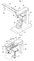
FIG. 1 is a perspective view of a dental complex imaging system according to the present invention. -
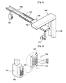
FIG. 2 is a perspective view of a support part of the dental complex imaging system according to the present invention. -
FIG. 3 is a perspective view of an expanding and contracting part of the dental complex imaging system according to the present invention. -
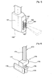
FIG. 4 is a perspective view of a radiation generator part of the dental complex imaging system according to the present invention. -
FIG. 5 is a perspective view of a detecting part of the dental complex imaging system according to the present invention. -
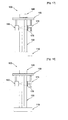
FIGS. 6 to 10 are views showing operational states during computed tomography (CT) imaging of the dental complex imaging system according to the present invention. -
FIGS. 11 to 14 are views showing operational states during cephalography of the dental complex imaging system according to the present invention. -
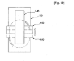
FIGS. 15 to 19 are views showing operational states during panoramic radiography of the dental complex imaging system according to the present invention. - To achieve the above objects, the present invention provides a dental complex imaging system comprising: a base seated on the ground; a chair part disposed on the upper portion of the base for allowing a patient to wait for imaging with him/her seated thereon; a pole mounted on the base so as to be adjacent to the chair part; a support part adapted to extend toward the patient from the top of the pole; an expanding and contracting part pivotally coupled to the underside of the support part so as to be expanded and contracted; a radiation generator part disposed below one side of the expanding and contracting part and moving according to expansion and contraction of the expanding and contracting part for emitting radiation selected according to computed tomography (CT) imaging, cephalography and panoramic radiography; a radiation detecting part disposed on the other side of the expanding and contracting part in such a way as to be opposed to the radiation generator part for detecting radiation selectively emitted from the radiation generator part according to the CT imaging, the cephalography and the panoramic radiography; and a control part for reading imaging information detected by the radiation detecting part.
- The radiation detecting part includes: a slide bar extended from the lower portion of the expanding and contracting part; an elevation body disposed on the slide bar in a slidably movable manner; an elevating part disposed between the slide bar and the elevation body for vertically conveying the elevation body along the slide bar; and a rectangular detector rotatably disposed on a side of the elevation body opposed to the radiation generator part.
- The support part includes: a housing adapted to form the outward appearance thereof and having an elongated hole formed on the lower surface thereof for allowing the expanding and contracting part to be connected to the support part; and an expanding and contracting part driver disposed inside the housing of the support part for straightly moving the rotational center of the expanding and contracting part.
- The expanding and contracting part driver includes: a conveyance body connected to the rotational center of the expanding and contracting part for rotating the expanding and contracting part; a guide coupled to a side of the conveyance body for guiding a straight reciprocating path of the conveyance body; and a conveying part coupled to the other side of the conveyance body for straightly reciprocating the conveyance body guided by the guide.
- When the CT imaging is conducted, the expanding and contracting part driver fixes a straight reciprocation of the conveyance body and rotates just the expanding and contracting part, so that the radiation generator part and the radiation detecting part disposed below the expanding and contracting part form a circular orbit.
- When the panoramic radiography is conducted, the expanding and contracting part driver straightly reciprocates the conveyance body and rotates the expanding and contracting part, so that the radiation generator part and the radiation detecting part disposed below the expanding and contracting part form an elliptical orbit.
- When the cephalography is conducted, the expanding and contracting part driver fixes the conveyance body in its straight reciprocating motion and also fixes the expanding and contracting part in its rotation.
- The expanding and contracting part includes: a fixed terminal rotatably coupled to the rotational center of the expanding and contracting part driver by the support part in such a way that the radiation detecting part is located below the fixed terminal; an expandable terminal slidably mounted with respect to the fixed terminal in such a way that the radiation generator part is located below the expandable terminal; and a guide bar disposed at both inner sides of the fixed terminal and both outer sides of the expandable terminal for guiding an expansion and contraction path of the expandable terminal.
- The radiation generator part includes: a radiation source for generating radiation; and a radiation collimator for selectively changing a cross part of radiation generated from the radiation source and selectively emitting the radiation according to the CT imaging, the cephalography and the panoramic radiography.
- The radiation collimator includes: a shutter body made of a lead (Pb) material, and having a CT imaging slit for emitting radiation necessary for the CT imaging when the CT imaging is conducted, a cephalography slit for emitting radiation necessary for the cephalography when the cephalography is conducted, and a panoramic radiography slit for emitting radiation necessary for the panoramic radiography when the panoramic radiography is conducted; and a pair of vertical guides coupled to both sides of the
shutter body 163 in a slidably movable manner for slidably moving the shutter body in a vertical direction. - The radiation detecting part further includes: a bracket mounted on a side of the elevation body; a detector rotatably disposed on the bracket; and a rotary motor disposed on the bracket for rotating the detector.
- When the CT imaging is conducted, the detector is located in a horizontal state, and obtains an image emitted from the radiation generator part according to the rotation of the expanding and contracting part.
- When the CT imaging is conducted, the detector is vertically moved to a position for conducting the CT imaging, and detects radiation to obtain an image of a wanted area.
- When the cephalography is conducted, the detector detects the radiation emitted from the radiation generator part in an area corresponding to a detection area of the detector while being vertically conveyed like the elevation body conveyed along the slide bar, and vertically moves as long as the area corresponding to the detection area of the detector to obtain an image of the patient's entire head.
- When the panoramic radiography is conducted, the detector is vertically rotated, and detects radiation emitted from the radiation generator part using some arrays of the detector according to the rotation of the expanding and contracting part.
- Referring to the attached drawing, a dental complex imaging system according to the present invention will be described in detail.
- In description of the present invention, the names of components are defined in consideration of functions of the present invention, and so it is to be appreciated that the names are not understood in a sense to restrict the technical components of the present invention and the names could be called different names by those skilled in the art. In addition, the reference numerals of the components are attached for convenience in description, and illustrated contents in the drawings having the reference numerals are not restrict the components within a range of the drawings. Moreover, if there are functional similarity and sameness of the components, they can be considered as an equal configuration even though a modification is adopted.
- First, referring to the attached drawings, the dental complex imaging system according to the present invention will be described in brief.
-
FIG. 1 is a perspective view of the dental complex imaging system according to the present invention. - As shown in the drawing, the dental complex imaging system 100 according to the present invention includes: a base 110 seated on the ground; a chair part 120 disposed on the upper portion of the base 110 for allowing a patient (not shown) to wait for imaging with him/her seated thereon; a pole 130 mounted on the base 110 so as to be adjacent to the chair part 120; a support part 140 adapted to extend toward the patient from the top of the pole 130; an expanding and contracting part 150 pivotally coupled to the underside of the support part 140 so as to expanded and contracted in a longitudinal direction; a radiation generator part 160 disposed below one side of the expanding and contracting part 150 and moving according to expansion and contraction of the expanding and contracting part 150 for emitting radiation selected according to computed tomography (CT) imaging, cephalography and panoramic radiography; a radiation detecting part 170 disposed on the other side of the expanding and contracting part 150 in such a way as to be opposed to the radiation generator part 160 for detecting radiation selectively emitted from the radiation generator part 160 according to the CT imaging, the cephalography and the panoramic radiography; and a control part (not shown) for controlling operations of the above parts and reading imaging information detected by the radiation detecting part 170.
- The
base 110 is to separate and fix thechair part 120 and thesupport part 140 at a fixed interval from each other, and may be constructed of a plate type. However, if necessary, thechair part 120 and thesupport part 140 may be mounted on the floor of a building. Alternatively, thechair part 120 may be mounted on the floor of the building, but thesupport part 140 may be mounted on a wall surface of the building. - The
chair part 120 allow the patient, who waits for the CT imaging, the cephalography and the panoramic radiography, to sit thereon, and includes achair 122 for allowing the patient to sit thereon and anelevation device 124 for adjusting a height of thechair 120 according to the patient's physical conditions. Theelevation device 124 may include a motor, which is electrically controlled, and an elevator, and it is preferable that theelevation device 124 is controlled by the control part (not shown). - In the meantime, the
chair part 120 may further include a support (not shown) mounted on the top of the back thereof for supporting the patient's back of the head. Moreover, the support of thechair part 120 may be mounted on the back of thechair 122 or fixed below a rotational center of thesupport part 140, which will be described later, in such a way as to fix the patient's head by being rotated against thesupport part 140. The support of the chair can be changed by one of various embodiments, and so, its detailed description will be omitted. - The
pole 130 is fixed on a side of thebase 110 for supporting thesupport part 140, namely, supports thesupport part 140 at a height corresponding to a height of the head of the patient, who sits on thechair part 120. Furthermore, thepole 130 may include an elevator (not shown) for adjusting a height of thesupport part 140 supported on the top of thepole 130. The elevator of thepole 130 can adjust heights of theradiation generator part 160 and theradiation detecting part 170 disposed on the expanding and contractingpart 150 in correspondence with the height of the head of the patient. - An end of the
support part 140 is supported on the top of thepole 130 for supporting the expanding and contractingpart 150 to thereby rotate the expanding and contractingpart 150 in a circular or elliptical orbit. - Hereinafter, referring to
FIG. 2 , thesupport part 140 will be described in detail.FIG. 2 is a perspective view of thesupport part 140 of the dentalcomplex imaging system 100 according to the present invention. - As shown in
FIG. 2 , thesupport part 140 of the dentalcomplex imaging system 100 includes: ahousing 140a forming the outward appearance thereof and having anelongated hole 141 formed on the lower surface thereof for allowing the expanding andcontracting part 150 to be connected to thesupport part 140; and an expanding and contracting part driver 142 disposed inside thehousing 140a for rotating or straightly moving the expanding andcontracting part 150. - Here, the expanding and
contracting part 150 rotates the expanding andcontracting part 150 and simultaneously moves the rotational center of the expanding andcontracting part 150 in a straight direction to thereby make the orbits of theradiation generator part 160 and theradiation detecting part 170, which are disposed at both ends of the expanding andcontracting part 150, in a circular form or an elliptical form. - The expanding and contracting part driver 142 includes: a
conveyance body 143 connected to the rotational center of the expanding andcontracting part 150 for rotating the expanding andcontracting part 150; aguide 146 coupled to a side of theconveyance body 143 for guiding a transfer path of theconveyance body 143; and a conveyingpart 147 coupled to the other side of theconveyance body 143 for conveying theconveyance body 143 guided by theguide 146. here, theconveyance body 143 includes arotary motor 144 for rotating the expanding andcontracting part 150 and a power transferring device 145, such as a belt and a pulley, for transferring driving power of the rotary motor to a rotary shaft (not shown) of the expanding andcontracting part 150. The conveyingpart 147 includes ahorizontal ball screw 148, to which theconveyance body 143 is coupled conveyably, and a horizontal conveyingmotor 149 for giving a rotational force to thehorizontal ball screw 148. - So, the
radiation generator part 160 and theradiation detecting part 170 form the circular orbit while the expanding andcontracting part 150 is rotated by the operation of therotary motor 144, and are rotated in such a way as to form the elliptical orbit while theconveyance body 143 performs a straight reciprocating motion. - The expanding and
contracting part 150 is rotated in a state where it is connected to the expanding and contracting part driver 142, and reduces a distance between theradiation generator part 160 and theradiation detecting part 170 during the CT imaging and the panoramic radiography, but enlarges the distance between theradiation generator part 160 and theradiation detecting part 170 during the cephalography. - Hereinafter, referring to
FIG. 3 , the expanding andcontracting part 150 will be described in detail.FIG. 3 is a perspective view of the expanding andcontracting part 150 of the dental complex imaging system according to the present invention. - As shown in
FIG. 3 , the expanding andcontracting part 150 of the dental complex imaging system according to the present invention includes: a fixedterminal 152 coupled to the rotational center of the expanding and contracting part driver 142 of thesupport part 140 in such a way that theradiation detecting part 170 is located below the fixedterminal 152; anexpandable terminal 154 slidably mounted with respect to the fixedterminal 152 in such a way that theradiation generator part 160 is located below theexpandable terminal 154; and aguide bar 156 disposed at both inner sides of the fixedterminal 152 and both outer sides of theexpandable terminal 154 for guiding an expansion and contraction path of theexpandable terminal 154. - Here, the fixed
terminal 152 has a predetermined length, is formed in a case type, and includes a rotary shaft (not shown) formed at the upper central portion thereof in such a way as to pass through theelongated hole 141 of thesupport part 140 and be coupled to the expanding and contracting part driver 142 of thesupport part 140. - The
guide bar 156 disposed at both inner sides of the fixedterminal 152 has a pair of LM guides oppositely coupled to the inner sides of the fixedterminal 152. The fixedterminal 152 has rails formed on both inner sides thereof and coupled with the LM guides, and theexpandable terminal 154 also has rails formed on both outer sides thereof and coupled with the LM guides. So, a distance of theexpandable terminal 154 expanded and contracted against the fixedterminal 152 can be increased up to thrice as long as a length of the fixedterminal 152. However, the distance between the fixedterminal 152 and theexpandable terminal 154 is not restricted to the above, and can be adjusted as occasion demands. - The
radiation generator part 160 is to selectively emit radiation necessary for CT imaging, cephalography and panoramic radiography when the CT imaging, the cephalography and the panoramic radiography are conducted. - Hereinafter, referring to
FIG. 4 , theradiation generator part 160 will be described in detail.FIG. 4 is a perspective view of the radiation generator part of the dental complex imaging system according to the present invention. - As shown in
FIG. 4 , theradiation generator part 160 of the dentalcomplex imaging system 100 according to the present invention includes: aradiation source 161 for generating radiation; and aradiation collimator 162 for selectively changing a cross part of radiation generated from theradiation source 161 and emitting radiation according to the CT imaging, the cephalography and the panoramic radiography. - Here, the
radiation source 161 includes a generator, a high voltage supplier, and a cooler. The components of theradiation source 161 are well known, and so, their detailed description will be omitted. - The
radiation collimator 162 is disposed on the radiation emitter (not shown) of theradiation source 161 for changing the cross part of the emitted radiation and emitting the radiation. Theradiation collimator 162 is made of a lead (Pb) material to prevent a leakage of radiation, and includes ashutter body 163 having a number of radiation emitting slits, and a pair ofvertical guides 167 coupled to both sides of theshutter body 163 in a slidably movable manner for slidably moving theshutter body 163 in a vertical direction. - Here, the
shutter body 163 has a CT imaging slit 164 for emitting radiation necessary for the CT imaging when the CT imaging is conducted, acephalography slit 165 for emitting radiation necessary for the cephalography when the cephalography is conducted, and a panoramic radiography slit 166 for emitting radiation necessary for the panoramic radiography when the panoramic radiography is conducted. - In the meantime, shapes of the
slits - The
radiation detecting part 170 is to selectively detect the radiation selectively emitted from theradiation generator part 160 during the CT imaging, the cephalography and the panoramic radiography according to the CT imaging, the cephalography and the panoramic radiography. - Hereinafter, referring to
FIG. 5 , theradiation detecting part 170 will be described in detail.FIG. 5 is a perspective view of theradiation detecting part 170 of the dental complex imaging system according to the present invention. - As shown in
FIG. 5 , theradiation detecting part 170 of the dentalcomplex imaging system 100 according to the present invention includes: aslide bar 171 extended from the lower portion of the fixedterminal 152 of the expanding andcontracting part 150; anelevation body 172 disposed on theslide bar 171 in a slidably movable manner; an elevatingpart 173 disposed between theslide bar 171 and theelevation body 172 for vertically conveying theelevation body 172 along theslide bar 171; and adetector 176 rotatably disposed on a side of the elevation body 172 (side opposed to the radiation generator part 160). - Here, the elevating
part 173 is to convey theelevation body 172, which is coupled to theslide bar 171 in the slidably movable manner, along theslide bar 171, and includes: avertical ball screw 174 disposed in parallel with theslide bar 171; and a vertically drivingmotor 175 for transferring driving power to thevertical ball screw 174. - In addition, the
detector 176 is rotatably disposed on a side of abracket 177 mounted on a side of theelevation body 172, and arotary motor 178 is disposed on the other side of thebracket 177 for rotating thedetector 176. Thedetector 176 is in a rectangular form, keeps a horizontal state during the CT imaging and the cephalography but is vertically rotated during the panoramic radiography. - Here, the
detector 176 is to detect radiation using various phenomena, such as ionization, chemical changes, generation of heat, formation of a track, exposure to light, and so on according to incidence of radiation, and uses an array X-ray sensing element, which can digitalize an amount of detected radiation. Since the array X-ray sensing element of the detector is well known, its detailed description will be omitted. - Now, the operation of the dental complex imaging system according to the present invention will be described in detail. Each component mentioned hereinafter should be understood in reference with the description and drawings.
- Here, the dental complex imaging system according to the present invention can conduct the CT imaging, the cephalography, and panoramic radiography by a simple manipulation. Each imaging method will be described in detail.
- First, referring to drawings, the CT imaging using the dental complex imaging system according to the present invention will be described in detail.
-
FIGS. 6 to 10 are views showing operational states during the CT imaging of the dental complex imaging system according to the present invention. - Here,
FIG. 6 illustrates an installation state of the dental complex imaging system when the CT imaging is conducted,FIG. 7 illustrates a mounting state of the radiation generator part of the dental complex imaging system when the CT imaging is conducted,FIG. 8 illustrates a mounting state of the radiation detecting part of the dental complex imaging system when the CT imaging is conducted, andFIGS. 9 and 10 illustrate the interrelation between the radiation generator part and the radiation detecting part when the CT imaging is conducted. - As shown in
FIG. 6 , when the CT imaging is conducted, the expanding andcontracting part 150 of the dentalcomplex imaging system 100 is contracted, so that the distance between theradiation generator part 160 and theradiation detecting part 170 is kept in a contracted state for the CT imaging. In this instance, thechair part 120 is manipulated in such a way that the patient's head is located at the center of theradiation generator part 160 and theradiation detecting part 170. - In the meantime, the
radiation collimator 162 of theradiation generator part 160 is located in such a way that theshutter body 163 is moved along thevertical guide 167 to emit radiation through the CT imaging slit 164 for the CT imaging. (SeeFIG. 7 ). - Moreover, the
detector 176 of theradiation detecting part 170 is located in a horizontal state, and theelevation body 172, to which thedetector 176 is coupled, is vertically conveyed to a position, where imaging is conducted, by thevertical ball screw 174 and thevertical driving motor 175 in such a way that a wanted portion is located at a radiation area. (SeeFIGS. 8 and9 ) - Hereinafter, the expanding and
contracting part 150 rotatably supported by thesupport part 140 is rotated by the expanding and contracting part driver 142 around the patient's head. In this instance, theconveyance body 143 of the expanding and contracting part driver 142 rotates 360 degrees in the circular orbit while it is fixed in its horizontal movement and the expanding andcontracting part 150 is rotated by therotary motor 144. (SeeFIG. 10 ) - According to the rotation of the expanding and
contracting part 150, the CT imaging slit 164 of theradiation collimator 162 disposed on theradiation generator part 160 emits radiation, and the emitted radiation passes through the patient's head and is detected by the detector of theradiation detecting part 170. Meanwhile, data detected from the detector of theradiation detecting part 170 is read by the control part (not shown) and outputted through a display device (not shown). - Hereinafter, referring to drawings, a case that the cephalography is conducted using the dental complex imaging system according to the present invention will be described in detail.
-
FIGS. 11 to 14 are views showing operational states during cephalography of the dental complex imaging system according to the present invention. - Here,
FIG. 11 illustrates an installation state of the dental complex imaging system when the cephalography is conducted,FIG. 12 illustrates a mounting state of the radiation generator part of the dental complex imaging system when the cephalography is conducted,FIG. 13 illustrates a mounting state of the radiation detecting part of the dental complex imaging system when the cephalography is conducted, andFIG. 14 illustrates the interrelation between the radiation generator part and the radiation detecting part when the cephalography is conducted. - As shown in
FIG. 11 , when the cephalography is conducted, the expanding andcontracting part 150 of the dentalcomplex imaging system 100 is expanded, so that the distance between theradiation generator part 160 and theradiation detecting part 170 is widened as long as a distance for the cephalography (here, the distance means a distance between the cephalography slit 165 of theradiation generator part 160 and the surface of thedetector 176 of theradiation detecting part 170, and may be 1,649mm). In this instance, thechair part 120 is manipulated in such a way that the patient's head is located adjacent to thedetector 176 of theradiation detecting part 170. - In the meantime, the
radiation collimator 162 of theradiation generator part 160 is located in such a way that theshutter body 163 is moved along thevertical guide 167 to emit radiation through the cephalography slit 165 for the cephalography. (SeeFIG. 12 ). - Moreover, the
detector 176 of theradiation detecting part 170 is located in a horizontal state, and theelevation body 172, to which thedetector 176 is coupled, is vertically conveyed by thevertical ball screw 174 of the elevatingpart 173 and thevertical driving motor 175 in such a way as to conduct imaging while being conveyed upwardly from the lowermost portion (or downwardly from the uppermost portion) of a imaging area in synchronization with the cephalography slit 165 of theradiation generator part 160. (SeeFIG. 13 ) - So, the cephalography slit 165 of the
radiation collimator 162 disposed on theradiation generator part 160 emits radiation, and the emitted radiation is emitted toward theradiation detecting part 170. At the same time, theelevation body 172 of theradiation detecting part 170 is moved in a vertically upward direction (or vertically downward direction) by thevertical ball screw 174 and thevertical driving motor 175 of the elevatingpart 173. - So, the
detector 176 detects an area corresponding to a detection area, vertically moves to the area corresponding to the detection area of thedetector 176, and detects radiation, which passes through the patient's head, by repeating the above. - Meanwhile, data detected from the detector of the
radiation detecting part 170 is read by the control part (not shown) and outputted through a display device (not shown). - Hereinafter, referring to drawings, a case that the panoramic radiography is conducted using the dental complex imaging system according to the present invention will be described in detail.
-
FIGS. 15 to 19 are views showing operational states during panoramic radiography of the dental complex imaging system according to the present invention. - Here,
FIG. 15 illustrates an installation state of the dental complex imaging system when the panoramic radiography is conducted,FIG. 16 illustrates a mounting state of the radiation generator part of the dental complex imaging system when the panoramic radiography is conducted,FIG. 17 illustrates an operational state of the radiation detecting part of the dental complex imaging system when the panoramic radiography is conducted, andFIGS. 18 and19 illustrate the interrelation between the radiation generator part and the radiation detecting part when the panoramic radiography is conducted. - As shown in
FIG. 15 , when the panoramic radiography is conducted, the expanding andcontracting part 150 of the dentalcomplex imaging system 100 is contracted, so that the distance between theradiation generator part 160 and theradiation detecting part 170 is kept in a contracted state for the panoramic radiography. In this instance, thechair part 120 is manipulated in such a way that the patient's head is located adjacent to thedetector 176 of theradiation detecting part 170. - In the meantime, the
radiation collimator 162 of theradiation generator part 160 is located in such a way that theshutter body 163 is moved along thevertical guide 167 to emit radiation through the panoramic radiography slit 166 for the panoramic radiography. (SeeFIG. 16 ). - Moreover, the
detector 176 of theradiation detecting part 170 is rotated by therotary motor 178 and located in a vertically rotated state, and theelevation body 172, to which thedetector 176 is coupled, is vertically conveyed by thevertical ball screw 174 and thevertical driving motor 175 in such a way that the lower end of thedetector 176 and the lower end portion of radiation emitted from theradiation generator part 160 are coincided with each other. (SeeFIGS. 17 and 189) - Hereinafter, the expanding and
contracting part 150 rotatably supported by thesupport part 140 is rotated by the expanding and contracting part driver 142 around the patient's head. - In this instance, the
conveyance body 143 of the expanding and contracting part driver 142 rotates in the elliptical orbit while it horizontally reciprocates along theguide 146 by thehorizontal ball screw 148 and thehorizontal driving motor 149 and the expanding andcontracting part 150 is rotated by therotary motor 144 disposed on theconveyance body 143. (SeeFIG. 19 ) - According to the rotation of the expanding and
contracting part 150, the panoramic radiography slit 166 of theradiation collimator 162 disposed on theradiation generator part 160 emits radiation, and the emitted radiation passes through the patient's head and is detected by the detector of theradiation detecting part 170. Meanwhile, data detected from the detector of theradiation detecting part 170 is read by the control part (not shown) and outputted through a display device (not shown). - In the meantime, when the panoramic radiography is conducted, it is possible that just some area of the
detector 176 is selectively used to obtain data. The reason is that a general 2-dimensional (rectangular) detector has a frame speed for obtaining an image of generally less than 30 frames per a second, but a 1-dimensional line detector is used for obtaining a panoramic image. - So, the panoramic image can be obtained in such a way as to selectively use some area of the rectangular detector 176 (preferably, a vertically linear detection area 176) and process data detected from the selected
detection area 176 at high speed. In addition, it is also possible to additionally mount a high speed data processing circuit (not shown) to process data detected in the selecteddetection area 176 at high speed. - Meanwhile, as described above, when the CT imaging, the cephalography and the panoramic radiography are conducted, the patient's scaned positions must be elevated according to the position of the
radiation detecting part 170, and the position of theradiation detecting part 170 can be adjusted by theelevation device 124. - As described above, while the present invention has been described with reference to the particular illustrative embodiment, it is not to be restricted by the embodiment but only by the appended claims. It is to be appreciated that those skilled in the art can change or modify the embodiment without departing from the scope of the present invention.
- For instance, additional components having additional functions can be added to the dental complex imaging system according to the present invention, or other components can be substituted with the components described in this embodiment. However, it is to be appreciated that all modifications belong to the technical category of the present invention if the modifications include the essential components of the present invention.
Claims (14)
- (amended) A dental complex imaging system (100) comprising
a base (110) seated on the ground;
a chair part (120) disposed on the upper portion of the base(110) for allowing a patient to wait for imaging with him/her seated thereon;
a pole (130) mounted on the base (110) as to be adjacent to the chair part (120);
a support part (140) adapted to extent toward the patient from the top of the pole (130);
an expanding and contracting part (150) pivotally coupled to the underside of the support part (140) so as to be expanded and contracted;
a radiation detecting part (170) disposed on the other side of the expanding and contracting part (150) in such a way as to be opposed to the radiation generator part (160) for detecting radiation selectively emitted from the radiation generator part (160) according to the CT-imaging, the cephalography and the panoramic radiography
a control part for reading imaging information detected by the radiation detecting part (170) characterized in that
a radiation generator part (160) is disposed below one side of the expanding and contracting part (150) and is moving according to expansion and contraction of the expanding and contracting part (150) for emitting radiation selected according to CT-imaging cephalography and panoramic radiography; wherein
the radiation detecting part comprises: a slide bar (171) extended from the lower portion of the expanding and contracting part (150); an elevation body (172) disposed on the slide bar in a slidably movable manner; an elevating part (173) disposed between the slide bar and the elevation body for vertically conveying the elevation body along the slide bar; and a rectangular detector (176) rotatably disposed on a side of the elevation body opposed to the radiation generator part. - The dental complex imaging system (100) according to claim 1, wherein the support part (140) comprises: a housing (140a) adapted to form the outward appearance thereof and having an elongated hole (141) formed on the lower surface thereof for allowing the expanding and contracting part (150) to be connected to the support part (140) ; and an expanding and contracting part driver (142) disposed inside the housing (140a) of the support part for straightly moving the rotational center of the expanding and contracting part (150).
- The dental complex imaging system (100) according to claim 2, wherein the expanding and contracting part driver (142) comprises: a conveyance body (143) connected to the rotational center of the expanding and contracting part (150) for rotating the expanding and contracting part (150); a guide (146) coupled to a side of the conveyance body (143) for guiding a straight reciprocating path of the conveyance body (143); and a conveying part (147) coupled to the other side of the conveyance body (143) for straightly reciprocating the conveyance body (143) guided by the guide (146).
- The dental complex imaging system (100) according to claim 3, wherein when the CT imaging is conducted, the expanding and contracting part driver (142) fixes a straight reciprocation of the conveyance body (143) and rotates just the expanding and contracting part (150), so that the radiation generator part (160) and the radiation detecting part (170) disposed below the expanding and contracting part (150) form a circular orbit.
- The dental complex imaging system (100) according to claim 3, wherein when the panoramic radiography is conducted, the expanding and contracting part driver (142) straightly reciprocates the conveyance body (143) and rotates the expanding and contracting part (150), so that the radiation generator part (160) and the radiation detecting part (170) disposed below the expanding and contracting part (150) form an elliptical orbit.
- The dental complex imaging system (100) according to claim 3, wherein when the cephalography is conducted, the expanding and contracting part driver (142) fixes the conveyance body (143) in its straight reciprocating motion and also fixes the expanding and contracting part (150) in its rotation.
- The dental complex imaging system (100) according to claim 1, wherein the expanding and contracting part (150) comprises: a fixed terminal (152) rotatably coupled to the rotational center of the expanding and contracting part driver (142) by the support part (140) in such a way that the radiation detecting (170) part is located below the fixed terminal (152) ; an expandable terminal (154) slidably mounted with respect to the fixed terminal (152) in such a way that the radiation generator part (160) is located below the expandable terminal (154); and a guide bar (156) disposed at both inner sides of the fixed terminal (152) and both outer sides of the expandable terminal (154) for guiding an expansion and contraction path of the expandable terminal (154).
- The dental complex imaging system (100) according to claim 1, wherein the radiation generator part (160) comprises: a radiation source (161) for generating radiation; and a radiation collimator (162) for selectively changing a cross part of radiation generated from the radiation source (161) and selectively emitting the radiation according to the CT imaging, the cephalography and the panoramic radiography.
- The dental complex imaging system (100) according to claim 8, wherein the radiation collimator (162) comprises: a shutter body (163) made of a lead (Pb) material, and having a CT imaging slit (164) for emitting radiation necessary for the CT imaging when the CT imaging is conducted, a cephalography slit (165) for emitting radiation necessary for the cephalography when the cephalography is conducted, and a panoramic radiography slit (166) for emitting radiation necessary for the panoramic radiography when the panoramic radiography is conducted; and a pair of vertical guides (167) coupled to both sides of the shutter body (163) in a slidably movable manner for slidably moving the shutter body (163) in a vertical direction.
- The dental complex imaging system (100) according to claim 1, wherein the radiation detecting part (170) further comprises: a bracket (177) mounted on a side of the elevation body (172) ; a detector (176) rotatably disposed on the bracket (177); and a rotary motor (178) disposed on the bracket (177) for rotating the detector (176).
- The dental complex imaging system (100) according to claim 1, wherein when the CT imaging is conducted, the detector (176) is located in a horizontal state, and detects radiation emitted from the radiation generator part (160) according to the rotation of the expanding and contracting part (150).
- The dental complex imaging system (100) according to claim 1, wherein when the cephalography is conducted, the detector (176) detects the radiation emitted from the radiation generator part (160) in an area corresponding to a detection area of the detector (176) while being vertically conveyed like the elevation body (172) conveyed along the slide bar (17)1, and detects the radiation while vertically moving as long as the area corresponding to the detection area of the detector (176).
- The dental complex imaging system (100) according to claim 1, wherein when the panoramic radiography is conducted, the detector (176) is vertically rotated, and detects radiation emitted from the radiation generator part (160) according to the rotation of the expanding and contracting part (150).
- The dental complex imaging system (100) according to claim 1, wherein when the panoramic radiography is conducted, the detector (176) is vertically rotated, selectively uses a vertically linear detection area of the detector (176), and processes data detected in the selected detection area to obtain a panoramic image.
Applications Claiming Priority (2)
| Application Number | Priority Date | Filing Date | Title |
|---|---|---|---|
| PCT/KR2006/003763 WO2008035828A1 (en) | 2006-09-22 | 2006-09-22 | Dental complex imaging system |
| PCT/KR2007/004667 WO2008035953A1 (en) | 2006-09-22 | 2007-09-21 | Complex imaging system for dental |
Publications (3)
| Publication Number | Publication Date |
|---|---|
| EP2063783A1 EP2063783A1 (en) | 2009-06-03 |
| EP2063783A4 EP2063783A4 (en) | 2010-07-21 |
| EP2063783B1 true EP2063783B1 (en) | 2014-04-23 |
Family
ID=39200641
Family Applications (1)
| Application Number | Title | Priority Date | Filing Date |
|---|---|---|---|
| EP07808434.0A Active EP2063783B1 (en) | 2006-09-22 | 2007-09-21 | Complex imaging system for dental |
Country Status (4)
| Country | Link |
|---|---|
| US (1) | US8005186B2 (en) |
| EP (1) | EP2063783B1 (en) |
| JP (1) | JP4996687B2 (en) |
| WO (2) | WO2008035828A1 (en) |
Families Citing this family (27)
| Publication number | Priority date | Publication date | Assignee | Title |
|---|---|---|---|---|
| US8290119B2 (en) * | 2007-01-24 | 2012-10-16 | Imaging Sciences International Llc | Adjustable scanner |
| WO2009105695A1 (en) * | 2008-02-20 | 2009-08-27 | Imaging Sciences International Llc | Adjustable scanner |
| FI123978B (en) | 2008-06-27 | 2014-01-15 | Planmeca Oy | dental Equipment |
| JP2010035984A (en) * | 2008-08-08 | 2010-02-18 | Canon Inc | X-ray imaging apparatus |
| KR101042935B1 (en) * | 2009-01-20 | 2011-06-20 | 주식회사바텍 | Lightweight X-ray camera |
| KR101684717B1 (en) | 2009-05-04 | 2016-12-08 | 트로피 | Combined panoramic and computed tomography apparatus |
| KR101094180B1 (en) * | 2009-11-10 | 2011-12-14 | 주식회사바텍 | Method and device for acquiring panoramic image |
| CN103458793B (en) * | 2010-12-22 | 2018-08-03 | 特罗菲公司 | Digital detector |
| KR101192461B1 (en) * | 2011-02-25 | 2012-10-17 | 이화여자대학교 산학협력단 | X-ray panorama imaging apparatus in oral cavity |
| EP2739209A1 (en) * | 2011-08-05 | 2014-06-11 | Trophy | Column height sensing for extra-oral imaging |
| ITBO20110566A1 (en) | 2011-10-05 | 2013-04-06 | Cefla Coop | DEVICE FOR THE ACQUISITION OF PANORAMIC RADIOGRAPHIES AND VOLUMETRIC CBCT RADIOGRAPHIES |
| ITBO20110764A1 (en) * | 2011-12-28 | 2013-06-29 | Cefla Coop | DEVICE FOR THE ACQUISITION OF PANORAMIC RADIOGRAPHIES, TELERADIOGRAPHIES AND OPTIONAL VOLUMETRIC CBCT RADIOGRAPHIES |
| KR101361076B1 (en) | 2012-03-12 | 2014-02-11 | (주)제노레이 | X-ray Imaging System |
| JP6370297B2 (en) * | 2012-09-07 | 2018-08-08 | トロフィー | Device for partial CT imaging |
| US9808211B2 (en) | 2013-11-12 | 2017-11-07 | Carestream Health, Inc. | Head and neck imager |
| KR20150088679A (en) * | 2014-01-24 | 2015-08-03 | 주식회사바텍 | Apparatus for Obtaining Computed Tomography |
| US9888891B2 (en) | 2014-06-26 | 2018-02-13 | Palodex Group Oy | X-ray imaging unit for medical imaging |
| FI20145617A7 (en) * | 2014-06-26 | 2015-12-27 | Palodex Group Oy | X-ray imaging unit for a medical imaging |
| CN105151651A (en) * | 2014-10-15 | 2015-12-16 | 杜昌峰 | Seat moving type queuing machine |
| CN108882904B (en) * | 2016-04-11 | 2022-09-20 | 专用成像有限责任公司 | C-arm with integrated CT system |
| US10390776B2 (en) | 2016-08-26 | 2019-08-27 | China Medical University | Three-dimentional serial focused intraoral digital tomosynthesis scanner and controlling method thereof |
| TWI642411B (en) * | 2016-08-26 | 2018-12-01 | 中國醫藥大學 | Intraoral cone-beam computed tomographic scanner and control method thereof |
| JP6666283B2 (en) * | 2017-02-23 | 2020-03-13 | 株式会社モリタ製作所 | X-ray tomography apparatus and X-ray tomography method |
| PE20211995A1 (en) * | 2018-10-25 | 2021-10-18 | Reliance Med Prod Inc | INTEGRATED PATIENT SUPPORT AND EQUIPMENT FOR MEDICAL PROCEDURES |
| US11000256B2 (en) * | 2018-11-09 | 2021-05-11 | Palodex Group Oy | Calibrating an X-ray medical imaging device for cephalometric imaging |
| JP7128488B2 (en) | 2020-10-06 | 2022-08-31 | フジキンソフト株式会社 | X-ray equipment |
| EP4186435A1 (en) * | 2021-11-26 | 2023-05-31 | Sirona Dental Systems GmbH | Device and method for generating dental x-ray images with highly specific dose application |
Family Cites Families (23)
| Publication number | Priority date | Publication date | Assignee | Title |
|---|---|---|---|---|
| JPS5841925Y2 (en) * | 1980-06-20 | 1983-09-22 | 株式会社 モリタ製作所 | Full-jaw X-ray imaging device that also performs head standard X-ray imaging |
| JPH0411691Y2 (en) * | 1985-06-25 | 1992-03-24 | ||
| DE3765558D1 (en) * | 1986-02-28 | 1990-11-22 | Siemens Ag | DENTAL X-RAY DIAGNOSTIC DEVICE FOR CREATING PANORAMIC LAYING FROM A PATIENT'S JAW. |
| JPH0715524Y2 (en) * | 1988-09-13 | 1995-04-12 | 株式会社モリタ製作所 | Dental panoramic cephalography system |
| EP0632995B1 (en) * | 1993-07-06 | 1999-04-21 | Sirona Dental Systems GmbH & Co.KG | Dental X-ray diagnostic device |
| JP3261262B2 (en) | 1994-07-08 | 2002-02-25 | 株式会社モリタ製作所 | Panoramic / cephalo combined X-ray imaging apparatus and cephalometric X-ray imaging apparatus |
| JP3807833B2 (en) * | 1996-12-10 | 2006-08-09 | 株式会社モリタ製作所 | X-ray equipment |
| WO2000057789A1 (en) * | 1999-03-25 | 2000-10-05 | Nihon University | Local irradiation x-ray ct imaging method and apparatus |
| FI116269B (en) * | 2000-02-18 | 2005-10-31 | Ge Healthcare Finland Oy | Procedure for imaging the cephalo area |
| DE10008053A1 (en) * | 2000-02-22 | 2001-09-06 | Siemens Ag | X-ray device and medical workplace for diagnostics and for surgical interventions in the head and jaw area of a patient |
| JP3964152B2 (en) * | 2000-05-01 | 2007-08-22 | 株式会社モリタ製作所 | X-ray sensor cassette and X-ray imaging apparatus |
| JP3964271B2 (en) * | 2001-06-22 | 2007-08-22 | 株式会社モリタ製作所 | Medical scanning digital X-ray imaging system |
| JP2003175027A (en) * | 2001-12-10 | 2003-06-24 | Hitachi Medical Corp | X-ray ct system |
| JP4149189B2 (en) * | 2002-04-04 | 2008-09-10 | 株式会社日立メディコ | X-ray CT system |
| WO2004014232A1 (en) * | 2002-07-25 | 2004-02-19 | Gendex Corporation | Real-time digital x-ray imaging apparatus and method |
| JP3931314B2 (en) * | 2002-12-27 | 2007-06-13 | 朝日レントゲン工業株式会社 | Dental X-ray equipment |
| DE10313110A1 (en) | 2003-03-24 | 2004-10-21 | Sirona Dental Systems Gmbh | X-ray device and X-ray sensitive camera |
| FI20070850L (en) * | 2005-04-11 | 2008-01-08 | Morita Mfg | An X-ray image sensor and an X-ray imaging device using it |
| FI118413B (en) * | 2005-04-11 | 2007-11-15 | Planmeca Oy | Computed tomography system |
| JP4307406B2 (en) * | 2005-04-22 | 2009-08-05 | 株式会社モリタ製作所 | Medical X-ray imaging apparatus and X-ray detector used therefor |
| KR100766332B1 (en) * | 2005-08-08 | 2007-10-11 | 주식회사바텍 | Panorama, Citi and Tofu X-ray System |
| EP1815794B1 (en) * | 2006-02-01 | 2015-11-04 | Gendex Corporation | Dental x-ray apparatus and method of positioning a patient therein |
| DE102006021373A1 (en) * | 2006-05-08 | 2007-11-15 | Siemens Ag | X-ray diagnostic device |
-
2006
- 2006-09-22 WO PCT/KR2006/003763 patent/WO2008035828A1/en not_active Ceased
-
2007
- 2007-09-21 EP EP07808434.0A patent/EP2063783B1/en active Active
- 2007-09-21 JP JP2009529130A patent/JP4996687B2/en active Active
- 2007-09-21 WO PCT/KR2007/004667 patent/WO2008035953A1/en not_active Ceased
- 2007-09-21 US US12/442,136 patent/US8005186B2/en active Active
Also Published As
| Publication number | Publication date |
|---|---|
| US8005186B2 (en) | 2011-08-23 |
| WO2008035953A1 (en) | 2008-03-27 |
| EP2063783A4 (en) | 2010-07-21 |
| EP2063783A1 (en) | 2009-06-03 |
| JP4996687B2 (en) | 2012-08-08 |
| WO2008035828A1 (en) | 2008-03-27 |
| JP2010503510A (en) | 2010-02-04 |
| US20090245461A1 (en) | 2009-10-01 |
Similar Documents
| Publication | Publication Date | Title |
|---|---|---|
| US8005186B2 (en) | Complex imaging system for dental | |
| JP7487172B2 (en) | Apparatus for digital imaging of the head region of a patient - Patent application | |
| CN106028941B (en) | Radiation imaging apparatus with improved functionality | |
| EP1752100B1 (en) | Combined panoramic and CT (computed tomography) X-ray apparatus | |
| CN101965153B (en) | Adjustable scanner | |
| US7424091B2 (en) | Combined panoramic, CT (computed tomography) and cephalometric photographing apparatus | |
| EP1752099B1 (en) | Combined panoramic and computed tomography photographing apparatus | |
| CN103027706B (en) | For obtaining the device of panorama radiography and CBCT volume radiographies | |
| EP3097854B1 (en) | Ct photographic device | |
| WO2015079120A1 (en) | Mammography imaging arrangement for tomosynthesis | |
| US20160213336A1 (en) | Apparatus and method for obtaining computed tomography | |
| KR20090030890A (en) | Dental Composite Imaging Device | |
| KR20090054447A (en) | Dental Composite Imaging Device | |
| KR20180042572A (en) | X-ray Imaging Apparatus Having Convertible Detector Array | |
| KR102665771B1 (en) | X-ray imaging device | |
| KR101310255B1 (en) | Panorama and cephalometric imaging system using same linear motion apparatus and sensor | |
| JP5998340B2 (en) | X-ray equipment | |
| KR20200000190A (en) | Panoramic X-ray Imaging Apparatus Which Provides With 2D Scanned X-ray Image | |
| KR102837952B1 (en) | X-ray Imaging Apparatus | |
| JP2019033810A (en) | Dental x-ray imaging apparatus | |
| JP2007143948A (en) | Cone beam x-ray ct apparatus | |
| US10405814B2 (en) | X-ray imaging apparatus and method for generating panoramic image using the same | |
| JP5618293B2 (en) | Medical X-ray equipment | |
| HK40067241A (en) | X-ray imaging apparatus | |
| HK40067241B (en) | X-ray imaging apparatus |
Legal Events
| Date | Code | Title | Description |
|---|---|---|---|
| PUAI | Public reference made under article 153(3) epc to a published international application that has entered the european phase |
Free format text: ORIGINAL CODE: 0009012 |
|
| 17P | Request for examination filed |
Effective date: 20090326 |
|
| AK | Designated contracting states |
Kind code of ref document: A1 Designated state(s): AT BE BG CH CY CZ DE DK EE ES FI FR GB GR HU IE IS IT LI LT LU LV MC MT NL PL PT RO SE SI SK TR |
|
| AX | Request for extension of the european patent |
Extension state: AL BA HR MK RS |
|
| A4 | Supplementary search report drawn up and despatched |
Effective date: 20100618 |
|
| DAX | Request for extension of the european patent (deleted) | ||
| 17Q | First examination report despatched |
Effective date: 20121004 |
|
| GRAP | Despatch of communication of intention to grant a patent |
Free format text: ORIGINAL CODE: EPIDOSNIGR1 |
|
| INTG | Intention to grant announced |
Effective date: 20131118 |
|
| GRAS | Grant fee paid |
Free format text: ORIGINAL CODE: EPIDOSNIGR3 |
|
| GRAA | (expected) grant |
Free format text: ORIGINAL CODE: 0009210 |
|
| AK | Designated contracting states |
Kind code of ref document: B1 Designated state(s): AT BE BG CH CY CZ DE DK EE ES FI FR GB GR HU IE IS IT LI LT LU LV MC MT NL PL PT RO SE SI SK TR |
|
| REG | Reference to a national code |
Ref country code: GB Ref legal event code: FG4D |
|
| REG | Reference to a national code |
Ref country code: CH Ref legal event code: EP |
|
| REG | Reference to a national code |
Ref country code: AT Ref legal event code: REF Ref document number: 663273 Country of ref document: AT Kind code of ref document: T Effective date: 20140515 |
|
| REG | Reference to a national code |
Ref country code: IE Ref legal event code: FG4D |
|
| REG | Reference to a national code |
Ref country code: DE Ref legal event code: R096 Ref document number: 602007036271 Country of ref document: DE Effective date: 20140605 |
|
| REG | Reference to a national code |
Ref country code: AT Ref legal event code: MK05 Ref document number: 663273 Country of ref document: AT Kind code of ref document: T Effective date: 20140423 |
|
| REG | Reference to a national code |
Ref country code: NL Ref legal event code: VDEP Effective date: 20140423 |
|
| REG | Reference to a national code |
Ref country code: LT Ref legal event code: MG4D |
|
| PG25 | Lapsed in a contracting state [announced via postgrant information from national office to epo] |
Ref country code: NL Free format text: LAPSE BECAUSE OF FAILURE TO SUBMIT A TRANSLATION OF THE DESCRIPTION OR TO PAY THE FEE WITHIN THE PRESCRIBED TIME-LIMIT Effective date: 20140423 Ref country code: FI Free format text: LAPSE BECAUSE OF FAILURE TO SUBMIT A TRANSLATION OF THE DESCRIPTION OR TO PAY THE FEE WITHIN THE PRESCRIBED TIME-LIMIT Effective date: 20140423 Ref country code: LT Free format text: LAPSE BECAUSE OF FAILURE TO SUBMIT A TRANSLATION OF THE DESCRIPTION OR TO PAY THE FEE WITHIN THE PRESCRIBED TIME-LIMIT Effective date: 20140423 Ref country code: GR Free format text: LAPSE BECAUSE OF FAILURE TO SUBMIT A TRANSLATION OF THE DESCRIPTION OR TO PAY THE FEE WITHIN THE PRESCRIBED TIME-LIMIT Effective date: 20140724 Ref country code: CY Free format text: LAPSE BECAUSE OF FAILURE TO SUBMIT A TRANSLATION OF THE DESCRIPTION OR TO PAY THE FEE WITHIN THE PRESCRIBED TIME-LIMIT Effective date: 20140423 Ref country code: BG Free format text: LAPSE BECAUSE OF FAILURE TO SUBMIT A TRANSLATION OF THE DESCRIPTION OR TO PAY THE FEE WITHIN THE PRESCRIBED TIME-LIMIT Effective date: 20140723 Ref country code: IS Free format text: LAPSE BECAUSE OF FAILURE TO SUBMIT A TRANSLATION OF THE DESCRIPTION OR TO PAY THE FEE WITHIN THE PRESCRIBED TIME-LIMIT Effective date: 20140823 |
|
| PG25 | Lapsed in a contracting state [announced via postgrant information from national office to epo] |
Ref country code: AT Free format text: LAPSE BECAUSE OF FAILURE TO SUBMIT A TRANSLATION OF THE DESCRIPTION OR TO PAY THE FEE WITHIN THE PRESCRIBED TIME-LIMIT Effective date: 20140423 Ref country code: PL Free format text: LAPSE BECAUSE OF FAILURE TO SUBMIT A TRANSLATION OF THE DESCRIPTION OR TO PAY THE FEE WITHIN THE PRESCRIBED TIME-LIMIT Effective date: 20140423 Ref country code: LV Free format text: LAPSE BECAUSE OF FAILURE TO SUBMIT A TRANSLATION OF THE DESCRIPTION OR TO PAY THE FEE WITHIN THE PRESCRIBED TIME-LIMIT Effective date: 20140423 Ref country code: SE Free format text: LAPSE BECAUSE OF FAILURE TO SUBMIT A TRANSLATION OF THE DESCRIPTION OR TO PAY THE FEE WITHIN THE PRESCRIBED TIME-LIMIT Effective date: 20140423 Ref country code: ES Free format text: LAPSE BECAUSE OF FAILURE TO SUBMIT A TRANSLATION OF THE DESCRIPTION OR TO PAY THE FEE WITHIN THE PRESCRIBED TIME-LIMIT Effective date: 20140423 |
|
| PG25 | Lapsed in a contracting state [announced via postgrant information from national office to epo] |
Ref country code: PT Free format text: LAPSE BECAUSE OF FAILURE TO SUBMIT A TRANSLATION OF THE DESCRIPTION OR TO PAY THE FEE WITHIN THE PRESCRIBED TIME-LIMIT Effective date: 20140825 |
|
| REG | Reference to a national code |
Ref country code: DE Ref legal event code: R097 Ref document number: 602007036271 Country of ref document: DE |
|
| PG25 | Lapsed in a contracting state [announced via postgrant information from national office to epo] |
Ref country code: SK Free format text: LAPSE BECAUSE OF FAILURE TO SUBMIT A TRANSLATION OF THE DESCRIPTION OR TO PAY THE FEE WITHIN THE PRESCRIBED TIME-LIMIT Effective date: 20140423 Ref country code: CZ Free format text: LAPSE BECAUSE OF FAILURE TO SUBMIT A TRANSLATION OF THE DESCRIPTION OR TO PAY THE FEE WITHIN THE PRESCRIBED TIME-LIMIT Effective date: 20140423 Ref country code: RO Free format text: LAPSE BECAUSE OF FAILURE TO SUBMIT A TRANSLATION OF THE DESCRIPTION OR TO PAY THE FEE WITHIN THE PRESCRIBED TIME-LIMIT Effective date: 20140423 Ref country code: EE Free format text: LAPSE BECAUSE OF FAILURE TO SUBMIT A TRANSLATION OF THE DESCRIPTION OR TO PAY THE FEE WITHIN THE PRESCRIBED TIME-LIMIT Effective date: 20140423 Ref country code: DK Free format text: LAPSE BECAUSE OF FAILURE TO SUBMIT A TRANSLATION OF THE DESCRIPTION OR TO PAY THE FEE WITHIN THE PRESCRIBED TIME-LIMIT Effective date: 20140423 Ref country code: BE Free format text: LAPSE BECAUSE OF FAILURE TO SUBMIT A TRANSLATION OF THE DESCRIPTION OR TO PAY THE FEE WITHIN THE PRESCRIBED TIME-LIMIT Effective date: 20140423 |
|
| PLBE | No opposition filed within time limit |
Free format text: ORIGINAL CODE: 0009261 |
|
| STAA | Information on the status of an ep patent application or granted ep patent |
Free format text: STATUS: NO OPPOSITION FILED WITHIN TIME LIMIT |
|
| PG25 | Lapsed in a contracting state [announced via postgrant information from national office to epo] |
Ref country code: IT Free format text: LAPSE BECAUSE OF FAILURE TO SUBMIT A TRANSLATION OF THE DESCRIPTION OR TO PAY THE FEE WITHIN THE PRESCRIBED TIME-LIMIT Effective date: 20140423 |
|
| 26N | No opposition filed |
Effective date: 20150126 |
|
| PG25 | Lapsed in a contracting state [announced via postgrant information from national office to epo] |
Ref country code: MC Free format text: LAPSE BECAUSE OF FAILURE TO SUBMIT A TRANSLATION OF THE DESCRIPTION OR TO PAY THE FEE WITHIN THE PRESCRIBED TIME-LIMIT Effective date: 20140423 Ref country code: LU Free format text: LAPSE BECAUSE OF FAILURE TO SUBMIT A TRANSLATION OF THE DESCRIPTION OR TO PAY THE FEE WITHIN THE PRESCRIBED TIME-LIMIT Effective date: 20140921 |
|
| REG | Reference to a national code |
Ref country code: DE Ref legal event code: R097 Ref document number: 602007036271 Country of ref document: DE Effective date: 20150126 |
|
| PG25 | Lapsed in a contracting state [announced via postgrant information from national office to epo] |
Ref country code: SI Free format text: LAPSE BECAUSE OF FAILURE TO SUBMIT A TRANSLATION OF THE DESCRIPTION OR TO PAY THE FEE WITHIN THE PRESCRIBED TIME-LIMIT Effective date: 20140423 |
|
| PG25 | Lapsed in a contracting state [announced via postgrant information from national office to epo] |
Ref country code: MT Free format text: LAPSE BECAUSE OF FAILURE TO SUBMIT A TRANSLATION OF THE DESCRIPTION OR TO PAY THE FEE WITHIN THE PRESCRIBED TIME-LIMIT Effective date: 20140423 |
|
| PG25 | Lapsed in a contracting state [announced via postgrant information from national office to epo] |
Ref country code: HU Free format text: LAPSE BECAUSE OF FAILURE TO SUBMIT A TRANSLATION OF THE DESCRIPTION OR TO PAY THE FEE WITHIN THE PRESCRIBED TIME-LIMIT; INVALID AB INITIO Effective date: 20070921 Ref country code: TR Free format text: LAPSE BECAUSE OF FAILURE TO SUBMIT A TRANSLATION OF THE DESCRIPTION OR TO PAY THE FEE WITHIN THE PRESCRIBED TIME-LIMIT Effective date: 20140423 |
|
| REG | Reference to a national code |
Ref country code: FR Ref legal event code: PLFP Year of fee payment: 10 |
|
| REG | Reference to a national code |
Ref country code: FR Ref legal event code: PLFP Year of fee payment: 11 |
|
| REG | Reference to a national code |
Ref country code: FR Ref legal event code: PLFP Year of fee payment: 12 |
|
| PGFP | Annual fee paid to national office [announced via postgrant information from national office to epo] |
Ref country code: IE Payment date: 20230920 Year of fee payment: 17 Ref country code: GB Payment date: 20230920 Year of fee payment: 17 |
|
| REG | Reference to a national code |
Ref country code: DE Ref legal event code: R079 Ref document number: 602007036271 Country of ref document: DE Free format text: PREVIOUS MAIN CLASS: A61B0006140000 Ipc: A61B0006510000 |
|
| PGFP | Annual fee paid to national office [announced via postgrant information from national office to epo] |
Ref country code: FR Payment date: 20230928 Year of fee payment: 17 Ref country code: DE Payment date: 20230920 Year of fee payment: 17 |
|
| PGFP | Annual fee paid to national office [announced via postgrant information from national office to epo] |
Ref country code: CH Payment date: 20231002 Year of fee payment: 17 |
|
| REG | Reference to a national code |
Ref country code: DE Ref legal event code: R119 Ref document number: 602007036271 Country of ref document: DE |
|
| REG | Reference to a national code |
Ref country code: CH Ref legal event code: PL |
|
| GBPC | Gb: european patent ceased through non-payment of renewal fee |
Effective date: 20240921 |
|
| PG25 | Lapsed in a contracting state [announced via postgrant information from national office to epo] |
Ref country code: DE Free format text: LAPSE BECAUSE OF NON-PAYMENT OF DUE FEES Effective date: 20250401 |
|
| PG25 | Lapsed in a contracting state [announced via postgrant information from national office to epo] |
Ref country code: GB Free format text: LAPSE BECAUSE OF NON-PAYMENT OF DUE FEES Effective date: 20240921 |
|
| PG25 | Lapsed in a contracting state [announced via postgrant information from national office to epo] |
Ref country code: FR Free format text: LAPSE BECAUSE OF NON-PAYMENT OF DUE FEES Effective date: 20240930 |
|
| PG25 | Lapsed in a contracting state [announced via postgrant information from national office to epo] |
Ref country code: CH Free format text: LAPSE BECAUSE OF NON-PAYMENT OF DUE FEES Effective date: 20240930 |
|
| PG25 | Lapsed in a contracting state [announced via postgrant information from national office to epo] |
Ref country code: IE Free format text: LAPSE BECAUSE OF NON-PAYMENT OF DUE FEES Effective date: 20240921 |