EP2063480A1 - Metallic bipolar plate for fuel cells and method for manufacturing the same - Google Patents
Metallic bipolar plate for fuel cells and method for manufacturing the same Download PDFInfo
- Publication number
- EP2063480A1 EP2063480A1 EP08020570A EP08020570A EP2063480A1 EP 2063480 A1 EP2063480 A1 EP 2063480A1 EP 08020570 A EP08020570 A EP 08020570A EP 08020570 A EP08020570 A EP 08020570A EP 2063480 A1 EP2063480 A1 EP 2063480A1
- Authority
- EP
- European Patent Office
- Prior art keywords
- substrate
- metallic
- noble metal
- substrates
- front surface
- Prior art date
- Legal status (The legal status is an assumption and is not a legal conclusion. Google has not performed a legal analysis and makes no representation as to the accuracy of the status listed.)
- Granted
Links
- 239000000446 fuel Substances 0.000 title claims abstract description 53
- 238000004519 manufacturing process Methods 0.000 title claims description 27
- 238000000034 method Methods 0.000 title claims description 12
- 239000000758 substrate Substances 0.000 claims abstract description 123
- 238000005219 brazing Methods 0.000 claims abstract description 73
- 229910000510 noble metal Inorganic materials 0.000 claims abstract description 58
- 239000000463 material Substances 0.000 claims abstract description 55
- 239000012495 reaction gas Substances 0.000 claims abstract description 32
- 229910045601 alloy Inorganic materials 0.000 claims abstract description 29
- 239000000956 alloy Substances 0.000 claims abstract description 29
- 229910001220 stainless steel Inorganic materials 0.000 claims abstract description 23
- 239000010935 stainless steel Substances 0.000 claims abstract description 22
- 229910001030 Iron–nickel alloy Inorganic materials 0.000 claims abstract description 13
- 238000005304 joining Methods 0.000 claims abstract description 6
- 238000005406 washing Methods 0.000 claims description 15
- 239000011248 coating agent Substances 0.000 claims description 12
- 238000000576 coating method Methods 0.000 claims description 12
- 238000004544 sputter deposition Methods 0.000 claims description 11
- 238000010306 acid treatment Methods 0.000 claims description 9
- 238000010438 heat treatment Methods 0.000 claims description 9
- 239000012528 membrane Substances 0.000 claims description 7
- 238000002844 melting Methods 0.000 claims description 5
- 238000010884 ion-beam technique Methods 0.000 claims description 4
- 230000001678 irradiating effect Effects 0.000 claims description 4
- 230000008018 melting Effects 0.000 claims description 4
- 239000010410 layer Substances 0.000 description 88
- 229910000679 solder Inorganic materials 0.000 description 28
- 238000012360 testing method Methods 0.000 description 15
- 229920005597 polymer membrane Polymers 0.000 description 10
- 238000005476 soldering Methods 0.000 description 9
- 230000000052 comparative effect Effects 0.000 description 8
- 239000007789 gas Substances 0.000 description 8
- 238000003825 pressing Methods 0.000 description 8
- 229910000831 Steel Inorganic materials 0.000 description 7
- 239000010959 steel Substances 0.000 description 7
- 239000002344 surface layer Substances 0.000 description 7
- HEMHJVSKTPXQMS-UHFFFAOYSA-M Sodium hydroxide Chemical compound [OH-].[Na+] HEMHJVSKTPXQMS-UHFFFAOYSA-M 0.000 description 6
- 229910001566 austenite Inorganic materials 0.000 description 6
- QDOXWKRWXJOMAK-UHFFFAOYSA-N dichromium trioxide Chemical compound O=[Cr]O[Cr]=O QDOXWKRWXJOMAK-UHFFFAOYSA-N 0.000 description 6
- 239000007787 solid Substances 0.000 description 6
- 238000005260 corrosion Methods 0.000 description 5
- 230000007797 corrosion Effects 0.000 description 5
- 238000001312 dry etching Methods 0.000 description 5
- 229910052751 metal Inorganic materials 0.000 description 5
- 239000002184 metal Substances 0.000 description 5
- 238000007747 plating Methods 0.000 description 5
- 238000003466 welding Methods 0.000 description 5
- CSCPPACGZOOCGX-UHFFFAOYSA-N Acetone Chemical compound CC(C)=O CSCPPACGZOOCGX-UHFFFAOYSA-N 0.000 description 4
- VEXZGXHMUGYJMC-UHFFFAOYSA-N Hydrochloric acid Chemical compound Cl VEXZGXHMUGYJMC-UHFFFAOYSA-N 0.000 description 4
- QAOWNCQODCNURD-UHFFFAOYSA-N Sulfuric acid Chemical compound OS(O)(=O)=O QAOWNCQODCNURD-UHFFFAOYSA-N 0.000 description 4
- 229910052737 gold Inorganic materials 0.000 description 4
- XLYOFNOQVPJJNP-UHFFFAOYSA-N water Substances O XLYOFNOQVPJJNP-UHFFFAOYSA-N 0.000 description 4
- 229920000049 Carbon (fiber) Polymers 0.000 description 3
- UFHFLCQGNIYNRP-UHFFFAOYSA-N Hydrogen Chemical compound [H][H] UFHFLCQGNIYNRP-UHFFFAOYSA-N 0.000 description 3
- 239000004917 carbon fiber Substances 0.000 description 3
- 238000007598 dipping method Methods 0.000 description 3
- 238000007599 discharging Methods 0.000 description 3
- 239000001257 hydrogen Substances 0.000 description 3
- 229910052739 hydrogen Inorganic materials 0.000 description 3
- VNWKTOKETHGBQD-UHFFFAOYSA-N methane Chemical compound C VNWKTOKETHGBQD-UHFFFAOYSA-N 0.000 description 3
- 238000000926 separation method Methods 0.000 description 3
- 229910017944 Ag—Cu Inorganic materials 0.000 description 2
- XKRFYHLGVUSROY-UHFFFAOYSA-N Argon Chemical compound [Ar] XKRFYHLGVUSROY-UHFFFAOYSA-N 0.000 description 2
- IJGRMHOSHXDMSA-UHFFFAOYSA-N Atomic nitrogen Chemical compound N#N IJGRMHOSHXDMSA-UHFFFAOYSA-N 0.000 description 2
- 239000002253 acid Substances 0.000 description 2
- 239000007864 aqueous solution Substances 0.000 description 2
- 239000010953 base metal Substances 0.000 description 2
- 239000003054 catalyst Substances 0.000 description 2
- 230000006835 compression Effects 0.000 description 2
- 238000007906 compression Methods 0.000 description 2
- 238000005238 degreasing Methods 0.000 description 2
- 238000009792 diffusion process Methods 0.000 description 2
- 230000005611 electricity Effects 0.000 description 2
- 239000010419 fine particle Substances 0.000 description 2
- 239000002737 fuel gas Substances 0.000 description 2
- 229910000743 fusible alloy Inorganic materials 0.000 description 2
- GPRLSGONYQIRFK-UHFFFAOYSA-N hydron Chemical compound [H+] GPRLSGONYQIRFK-UHFFFAOYSA-N 0.000 description 2
- 150000004767 nitrides Chemical class 0.000 description 2
- 235000014593 oils and fats Nutrition 0.000 description 2
- 239000007800 oxidant agent Substances 0.000 description 2
- 229910052763 palladium Inorganic materials 0.000 description 2
- 230000002093 peripheral effect Effects 0.000 description 2
- 229910052697 platinum Inorganic materials 0.000 description 2
- 238000004881 precipitation hardening Methods 0.000 description 2
- 229910052707 ruthenium Inorganic materials 0.000 description 2
- 238000007711 solidification Methods 0.000 description 2
- 230000008023 solidification Effects 0.000 description 2
- 238000000638 solvent extraction Methods 0.000 description 2
- 239000004094 surface-active agent Substances 0.000 description 2
- 230000007306 turnover Effects 0.000 description 2
- 229910000859 α-Fe Inorganic materials 0.000 description 2
- OKTJSMMVPCPJKN-UHFFFAOYSA-N Carbon Chemical compound [C] OKTJSMMVPCPJKN-UHFFFAOYSA-N 0.000 description 1
- GRYLNZFGIOXLOG-UHFFFAOYSA-N Nitric acid Chemical compound O[N+]([O-])=O GRYLNZFGIOXLOG-UHFFFAOYSA-N 0.000 description 1
- 229910020220 Pb—Sn Inorganic materials 0.000 description 1
- 229910020836 Sn-Ag Inorganic materials 0.000 description 1
- 229910020830 Sn-Bi Inorganic materials 0.000 description 1
- 229910020888 Sn-Cu Inorganic materials 0.000 description 1
- 229910020988 Sn—Ag Inorganic materials 0.000 description 1
- 229910018728 Sn—Bi Inorganic materials 0.000 description 1
- 229910019204 Sn—Cu Inorganic materials 0.000 description 1
- 229910009071 Sn—Zn—Bi Inorganic materials 0.000 description 1
- 229910052786 argon Inorganic materials 0.000 description 1
- 239000012298 atmosphere Substances 0.000 description 1
- QVGXLLKOCUKJST-UHFFFAOYSA-N atomic oxygen Chemical compound [O] QVGXLLKOCUKJST-UHFFFAOYSA-N 0.000 description 1
- 230000015572 biosynthetic process Effects 0.000 description 1
- 229910052799 carbon Inorganic materials 0.000 description 1
- 229910052804 chromium Inorganic materials 0.000 description 1
- 239000000470 constituent Substances 0.000 description 1
- 239000000498 cooling water Substances 0.000 description 1
- 230000003247 decreasing effect Effects 0.000 description 1
- 230000000994 depressogenic effect Effects 0.000 description 1
- 238000001035 drying Methods 0.000 description 1
- 230000000694 effects Effects 0.000 description 1
- 238000009713 electroplating Methods 0.000 description 1
- 238000005516 engineering process Methods 0.000 description 1
- 238000005530 etching Methods 0.000 description 1
- 238000002474 experimental method Methods 0.000 description 1
- 229910001119 inconels 625 Inorganic materials 0.000 description 1
- 238000011835 investigation Methods 0.000 description 1
- 150000002500 ions Chemical class 0.000 description 1
- 230000000873 masking effect Effects 0.000 description 1
- 150000002739 metals Chemical class 0.000 description 1
- 238000012986 modification Methods 0.000 description 1
- 230000004048 modification Effects 0.000 description 1
- 229910052759 nickel Inorganic materials 0.000 description 1
- 229910017604 nitric acid Inorganic materials 0.000 description 1
- 229910052757 nitrogen Inorganic materials 0.000 description 1
- 239000003960 organic solvent Substances 0.000 description 1
- 230000001590 oxidative effect Effects 0.000 description 1
- 239000001301 oxygen Substances 0.000 description 1
- 229910052760 oxygen Inorganic materials 0.000 description 1
- 239000002994 raw material Substances 0.000 description 1
- 230000003014 reinforcing effect Effects 0.000 description 1
- 230000000717 retained effect Effects 0.000 description 1
- 238000007789 sealing Methods 0.000 description 1
- 239000003566 sealing material Substances 0.000 description 1
- 238000004381 surface treatment Methods 0.000 description 1
- 238000007740 vapor deposition Methods 0.000 description 1
Images



Classifications
-
- H—ELECTRICITY
- H01—ELECTRIC ELEMENTS
- H01M—PROCESSES OR MEANS, e.g. BATTERIES, FOR THE DIRECT CONVERSION OF CHEMICAL ENERGY INTO ELECTRICAL ENERGY
- H01M8/00—Fuel cells; Manufacture thereof
- H01M8/02—Details
- H01M8/0202—Collectors; Separators, e.g. bipolar separators; Interconnectors
- H01M8/0204—Non-porous and characterised by the material
- H01M8/0206—Metals or alloys
- H01M8/0208—Alloys
-
- H—ELECTRICITY
- H01—ELECTRIC ELEMENTS
- H01M—PROCESSES OR MEANS, e.g. BATTERIES, FOR THE DIRECT CONVERSION OF CHEMICAL ENERGY INTO ELECTRICAL ENERGY
- H01M8/00—Fuel cells; Manufacture thereof
- H01M8/02—Details
- H01M8/0202—Collectors; Separators, e.g. bipolar separators; Interconnectors
- H01M8/0204—Non-porous and characterised by the material
- H01M8/0206—Metals or alloys
- H01M8/0208—Alloys
- H01M8/021—Alloys based on iron
-
- H—ELECTRICITY
- H01—ELECTRIC ELEMENTS
- H01M—PROCESSES OR MEANS, e.g. BATTERIES, FOR THE DIRECT CONVERSION OF CHEMICAL ENERGY INTO ELECTRICAL ENERGY
- H01M8/00—Fuel cells; Manufacture thereof
- H01M8/02—Details
- H01M8/0202—Collectors; Separators, e.g. bipolar separators; Interconnectors
- H01M8/0204—Non-porous and characterised by the material
- H01M8/0223—Composites
- H01M8/0228—Composites in the form of layered or coated products
-
- H—ELECTRICITY
- H01—ELECTRIC ELEMENTS
- H01M—PROCESSES OR MEANS, e.g. BATTERIES, FOR THE DIRECT CONVERSION OF CHEMICAL ENERGY INTO ELECTRICAL ENERGY
- H01M8/00—Fuel cells; Manufacture thereof
- H01M8/02—Details
- H01M8/0202—Collectors; Separators, e.g. bipolar separators; Interconnectors
- H01M8/0258—Collectors; Separators, e.g. bipolar separators; Interconnectors characterised by the configuration of channels, e.g. by the flow field of the reactant or coolant
-
- H—ELECTRICITY
- H01—ELECTRIC ELEMENTS
- H01M—PROCESSES OR MEANS, e.g. BATTERIES, FOR THE DIRECT CONVERSION OF CHEMICAL ENERGY INTO ELECTRICAL ENERGY
- H01M8/00—Fuel cells; Manufacture thereof
- H01M8/02—Details
- H01M8/0202—Collectors; Separators, e.g. bipolar separators; Interconnectors
- H01M8/0258—Collectors; Separators, e.g. bipolar separators; Interconnectors characterised by the configuration of channels, e.g. by the flow field of the reactant or coolant
- H01M8/0263—Collectors; Separators, e.g. bipolar separators; Interconnectors characterised by the configuration of channels, e.g. by the flow field of the reactant or coolant having meandering or serpentine paths
-
- H—ELECTRICITY
- H01—ELECTRIC ELEMENTS
- H01M—PROCESSES OR MEANS, e.g. BATTERIES, FOR THE DIRECT CONVERSION OF CHEMICAL ENERGY INTO ELECTRICAL ENERGY
- H01M8/00—Fuel cells; Manufacture thereof
- H01M8/02—Details
- H01M8/0297—Arrangements for joining electrodes, reservoir layers, heat exchange units or bipolar separators to each other
-
- H—ELECTRICITY
- H01—ELECTRIC ELEMENTS
- H01M—PROCESSES OR MEANS, e.g. BATTERIES, FOR THE DIRECT CONVERSION OF CHEMICAL ENERGY INTO ELECTRICAL ENERGY
- H01M8/00—Fuel cells; Manufacture thereof
- H01M8/24—Grouping of fuel cells, e.g. stacking of fuel cells
- H01M8/241—Grouping of fuel cells, e.g. stacking of fuel cells with solid or matrix-supported electrolytes
- H01M8/242—Grouping of fuel cells, e.g. stacking of fuel cells with solid or matrix-supported electrolytes comprising framed electrodes or intermediary frame-like gaskets
-
- H—ELECTRICITY
- H01—ELECTRIC ELEMENTS
- H01M—PROCESSES OR MEANS, e.g. BATTERIES, FOR THE DIRECT CONVERSION OF CHEMICAL ENERGY INTO ELECTRICAL ENERGY
- H01M8/00—Fuel cells; Manufacture thereof
- H01M8/24—Grouping of fuel cells, e.g. stacking of fuel cells
- H01M8/2457—Grouping of fuel cells, e.g. stacking of fuel cells with both reactants being gaseous or vaporised
-
- H—ELECTRICITY
- H01—ELECTRIC ELEMENTS
- H01M—PROCESSES OR MEANS, e.g. BATTERIES, FOR THE DIRECT CONVERSION OF CHEMICAL ENERGY INTO ELECTRICAL ENERGY
- H01M8/00—Fuel cells; Manufacture thereof
- H01M8/24—Grouping of fuel cells, e.g. stacking of fuel cells
- H01M8/2465—Details of groupings of fuel cells
- H01M8/2483—Details of groupings of fuel cells characterised by internal manifolds
-
- Y—GENERAL TAGGING OF NEW TECHNOLOGICAL DEVELOPMENTS; GENERAL TAGGING OF CROSS-SECTIONAL TECHNOLOGIES SPANNING OVER SEVERAL SECTIONS OF THE IPC; TECHNICAL SUBJECTS COVERED BY FORMER USPC CROSS-REFERENCE ART COLLECTIONS [XRACs] AND DIGESTS
- Y02—TECHNOLOGIES OR APPLICATIONS FOR MITIGATION OR ADAPTATION AGAINST CLIMATE CHANGE
- Y02E—REDUCTION OF GREENHOUSE GAS [GHG] EMISSIONS, RELATED TO ENERGY GENERATION, TRANSMISSION OR DISTRIBUTION
- Y02E60/00—Enabling technologies; Technologies with a potential or indirect contribution to GHG emissions mitigation
- Y02E60/30—Hydrogen technology
- Y02E60/50—Fuel cells
-
- Y—GENERAL TAGGING OF NEW TECHNOLOGICAL DEVELOPMENTS; GENERAL TAGGING OF CROSS-SECTIONAL TECHNOLOGIES SPANNING OVER SEVERAL SECTIONS OF THE IPC; TECHNICAL SUBJECTS COVERED BY FORMER USPC CROSS-REFERENCE ART COLLECTIONS [XRACs] AND DIGESTS
- Y02—TECHNOLOGIES OR APPLICATIONS FOR MITIGATION OR ADAPTATION AGAINST CLIMATE CHANGE
- Y02P—CLIMATE CHANGE MITIGATION TECHNOLOGIES IN THE PRODUCTION OR PROCESSING OF GOODS
- Y02P70/00—Climate change mitigation technologies in the production process for final industrial or consumer products
- Y02P70/50—Manufacturing or production processes characterised by the final manufactured product
Definitions
- the present invention relates to a metallic bipolar plate for fuel cells in which a pair of adjacent metallic plates are firmly and surely joined with each other and a method for manufacturing the same.
- a fuel cell of a unit cell is constituted of a membrane electrode assembly composed of a solid polymer membrane and gas diffusion layers formed on both sides thereof via a catalyst layer; and a pair of plates disposed on both sides of the membrane electrode assembly and having a channel of a reaction gas.
- a metallic bipolar plate with excellent press moldability is studied, and for example, those obtained by press forming a stainless steel sheet with excellent corrosion resistance are regarded to be potential.
- a fuel cell stack prepared by subjecting mutually adjacent anode plate and cathode plate of a unit fuel cell, after previously forming a nitride layer on a surface of every peripheral part of the both, to laser welding between such peripheral parts, thereby smoothening the nitride layer; and a method for manufacturing a bipolar plate for fuel cells (see, for example, pages 1 to 28 and Figs. 3 and 4 of JP-A-2007-73422 ).
- An object of the invention is to solve the problems which have been described in the above and to provide a metallic bipolar plate for fuel cells, in which a pair of metallic plates which are composed of a stainless steel, an Fe-Ni based alloy or an Ni-base alloy and are adjacent to each other can be firmly and surely joined with each other, and which can be inexpensively manufactured; and a method for manufacturing the same.
- the invention has been attained on the basis of intensive investigations and experiments made by the present inventors and achieved on an idea that joining of a pair of metallic plates which are made of a stainless steel or the like and are adjacent to each other is performed by brazing between the front surfaces thereof on each of which a passive film is not present and an extremely thin layer of a noble metal is coated.
- the present invention provides,
- a dry etching step for irradiating an ion beam and a sputtering step can be continuously carried out inside the same sputtering device, it is possible to easily and inexpensively manufacture a metallic bipolar plate to be used for fuel cells with a less warpage by substantially decreasing the number of steps as compared with the case of the first manufacturing method.
- the order in which after performing the pressing in advance, the foregoing three steps are carried out may also be adopted.
- Fig. 1 is a front view showing a metallic plate P2 for fuel cells of an embodiment which is used for the metallic bipolar plate for fuel cells according to the invention and along the sense orthogonal to its front surface 4.
- Fig. 2 is a cross-sectional view along an arrow of an X-X line in Fig. 1; and
- Fig. 3 is a cross-sectional view along an arrow of a Y-Y line in Fig. 1 .
- the metallic plate for fuel cells (hereinafter referred to simply as "metallic plate”) P2 is one obtained by press forming a thin sheet made of, for example, an austenite based stainless steel (for example, SUS316L) and having a thickness of about 0.1 mm. As illustrated in Figs. 1 to 3 , it is provided with a substrate 1 appearing substantially a regular square and its front surface 4 and back surface 5.
- a raw material of such a plate P2 may be an Fe-Ni based alloy or an Ni-base alloy.
- a plurality of concave portions 8 and convex portions 9 which are turnovers of the respective convex portions 7 and concave portions 8 are positioned substantially in a central portion on the back surface 5 of the metallic plate P2.
- a periphery 18 having a narrow width, a concave part 17 which is disposed adjacent along the entirety of the inside of the periphery 18 and a convex part 16 having a wide width which is disposed adjacent along the entirety of the inside of the concave part 17 are provided at the outer periphery on the front surface 4 of the metallic plate P2; and the channels 6, the convex portions 7, the header portions 10 and 11, the gas supplying portion 12 and the gas discharging portion 14 are positioned while being surrounded by the convex part 16.
- a convex part and a concave part which are turnovers of the periphery 18, the concave part 17 and the convex part 16 are provided at the outer periphery on the back surface 5 of the metallic plate P2; and the concave portions 8 and the convex portions 9 and the like are positioned while being surrounded thereby.
- the individual channels 6 of a reaction gas appear substantially a slender N-shape on a planar view; and the convex portions 7 positioning on the both sides thereof appear substantially a slender inverse N-shape on a planar view.
- a pair of U-turn portions u which are substantially a U-shape on a planar view is positioned in the midway of each of the channels 6.
- the reaction gas which flows through the channel 6 is a fuel gas such as hydrogen or an oxidizing agent gas such as air.
- an Au layer (thin layer of a noble metal) 3 having a thickness of from 0.5 to 60 nm is coated on each of the entireties of the both surfaces of the substrate 1 made of a stainless steel or an Fe-Ni based alloy.
- a passive film made of a Cr oxide which is usually formed on the surface of a stainless steel material or the like is not present between the substrate 1 and the respective Au layer 3, but the substrate 1 and the respective Au layer 3 come into direct contact with each other.
- the Au layer 3 may be provided on the front surface 4 of the metallic plate P2 in such a form that it is at least coated on only the entirety of a top surface of the convex portion 7 for partitioning the channel 6 of a reaction gas (a part of the front surface) or only a portion of such a top surface (a part of the front surface); and, on the back surface 5, that it is coated on only the entirety of a top surface of the concave portion 9 positioning on the opposite side of each channel 6 (a part of the back surface) or only a portion of such a top surface which includes a brazed portion as described later (part of the back surface).
- the first and second manufacturing methods for obtaining the metallic bipolar plate P3 for fuel cells according to the invention are described with reference to Figs. 4 to 9 .
- the metallic plate P2 is illustrated while being slightly simplified.
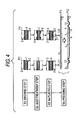
- Fig. 4 is concerned with a former stage of the first manufacturing method.
- a raw steel sheet P0 made of a stainless steel (for example, SUS316L) or an Fe-Ni based alloy (for example, INCOLOY825) and having a thickness of about 0.1 mm is the substrate 1 containing prescribed amounts of Cr and Ni and the like; and a passive film 2 having a thickness of about several nm and made of a Cr oxide (for example, Cr 2 O 3 , Cr(OH) 3 , etc.) is formed on the entirety of each of the front surface 4 and the back surface 5 thereof.
- a Cr oxide for example, Cr 2 O 3 , Cr(OH) 3 , etc.
- a washing step (S1) is carried out by washing the raw steel sheet P0 in surfactant-containing wash water or pure water to remove dusts attached on the front surface 4 and back surface 5, followed by dipping the steel sheet in a sodium hydroxide aqueous solution or an organic solvent such as acetone, thereby removing and degreasing oils and fats attached to the front surface and the back surface.
- a step (S2) of conducting an acid treatment by dipping the washed raw steel sheet P0 in a mixed acid (chiefly a mixed acid of sulfuric acid, nitric acid and hydrochloric acid), hydrochloric acid or sulfuric acid is carried out.
- a mixed acid chiefly a mixed acid of sulfuric acid, nitric acid and hydrochloric acid
- hydrochloric acid or sulfuric acid is carried out.
- the acid treatment by means of masking may also be adopted to form the substrate 1 from which the passive film has been removed from a part of each of the front surface 4 and the back surface 5.
- a step (S3) of applying electrolytic Au-plating to the entirety or a part of each of the front surface 4 and the back surface 5 of the substrate 1 to thereby coat the Au-plated layer (thin layer of a noble metal) 3 is carried out.
- a metallic plate raw sheet P1 in which the Au-plated layer 3 having a thickness of from 0.5 to 60 nm is coated on the entirety or a part of each of the front surface 4 and the back surface 5 of the substrate 1 is obtained.
- the step (S2) of an acid treatment to the step (S3) of coating the Au-plated layer 3 are carried out in a non-oxidizing atmosphere such as argon or nitrogen. Also, in the case of coating the Au-plated layer 3 on a part of each of the front surface 4 and the back surface 5 of the substrate 1, the electrolytic Au-plating or the like is carried out in a state that other part of each of the front surface 4 and the back surface 5 is masked.
- a step (S4) of press forming is carried out by inserting the metallic plate raw sheet P1 in which the Au-plated layer 3 is coated on each of the front surface 4 and the back surface 5 between a pair of non-illustrated press dies and then press forming the metallic plate raw sheet.
- Fig. 5 is concerned with a former stage in the second manufacturing method for obtaining the metallic bipolar plate P3 for fuel cells according to the invention.
- a washing step (S1) is carried out by bringing a raw steel sheet P0 into contact with surfactant-containing wash water, followed by dipping it in a sodium hydroxide aqueous solution or acetone to degrease and wash a front surface 4 and a back surface 5, thereby removing stains or oils and fats or the like attached to the surface layer.
- a dry etching step (S5) is carried out by conveying the raw steel P0, the front surface 4 and back surface 5 of which have been washed, into a high-vacuum sputtering device and irradiating it with an ion beam by an ion gas such as Ar, to thereby remove a passive film 2 formed on the entirety or a part of each of the front surface 4 and the back surface 5 in a required thickness (for example, about 20 nm) as illustrated in the respective right-and-left frames in the second stage in Fig. 5 .
- a step (S6) of applying sputtering by means of vapor deposition of Au (noble metal) disposed as a target on the entirety or a part of each of the front surface 4 and the back surface 5 of the raw steel sheet P0 immediately after drying etching inside the sputtering device is carried out.
- a metallic plate raw sheet P1 in which an Au-sputtered layer (thin layer of a noble metal) 3 having a thickness of from 0.5 to 60 nm is directly coated on the entirety or apart of each of the front surface 4 and the back surface 5 of the substrate 1 is obtained.
- Figs. 6 to 8 are concerned with a latter stage of the manufacturing method of the metallic bipolar plate P3 which is common in the first and second manufacturing methods according to the invention.
- a pair of the metallic plates P2 is made to come close to each other such that the back surfaces 5 and 5, on each of which the channels 6 are not formed face, each other.
- a paste-shaped solder (brazing material) R is coated in advance in a linear form, a dotted form or a planar form.
- the solder (brazing material) R is positioned above the thin layer 3 of Au (noble metal).
- a paste-shaped or preform material made of a low-melting alloy such as Sn-Ag based, Sn-Cu based, Sn-Ag-Cu based, Sn-Ag-Bi based, Sn-Bi based or Sn-Zn-Bi based alloys may be used for the brazing material R to be used in the invention in place of the foregoing solder (Pb-Sn).
- the paste-shaped solder R is disposed such that it is interposed between the Au thin layers (Au-plated layers or Au-sputtered layers) 3 and 3 coated on the entirety of each of the back surfaces 5 of a pair of the metallic plates P2.
- a pair of the metallic plates P2 is restrained in such a state, followed by heating at about 200°C for several seconds.
- the solder R is once melted and then solidified for compression.
- the solder R after solidification is directly brazed (joined) with the respective substrates 1 of a pair of the metallic plates P2.
- the paste-shaped solder R may be disposed such that it is interposed between the Au thin layers 3 and 3 coated on a part of each of the back surfaces 5 of a pair of the metallic plates P2.
- a pair of the metallic plates P2 is restrained in such a state, followed by heating at about 200 °C for several seconds.
- the solder R is once melted and then solidified for compression.
- the Au atom in the Au thin layer 3 is diffused into the adjacent solder R by means of the foregoing heating, the solder R after solidification is directly brazed (joined) with the respective substrates 1 of a pair of the metallic plates P2.
- the directly brazed joint portion may occupy 30% or more, desirably 40% or more, and more preferably 50% or more of an area at the interface between the substrate 1 and the solder (brazing material) R.
- the direct brazing between the substrate 1 and the solder R is caused due to the matter that it becomes possible to achieve the foregoing diffusion because the Au-plated layer 3 is an extremely thin membrane having a thickness of from 0.5 to 60 nm, and desirably from 1 to 20 nm.
- a pair of the metallic plates P2 can be firmly and surely brazed in a relatively low heating temperature range.
- a pair of the metallic plates P2 is brazed via the low-melting solder R by means of the foregoing soldering (brazing) between the back surfaces 5 and 5 faced and made to come close to each other such that the respective channels 6 are mutually orthogonal.
- soldering brazing
- the substrates 1 and 1 of the metallic plates P2 and P2 can be firmly and surely joined with each other via only the solder R soldered at a relatively low temperature without mediating the passive film 2. Accordingly, it is possible to easily and inexpensively provide the metallic bipolar plate P3 in which a pair of the metallic plates P2 which have corrosion resistance and are free from a warpage are firmly joined with each other.
- Fig. 10 is concerned with steps for preparing a fuel cell B1 of a unit cell using the metallic bipolar plate P3.
- a central polymer membrane body 20 and a pair of electrodes 26 to be disposed on the both sides thereof are interposed between a pair of the metallic bipolar plates P3.
- the polymer membrane body 20 is a membrane material which has substantially the same size as the metallic plate P2 as a whole and is composed of a central solid polymer membrane 22 and a reinforcing sealing portion 24 of a frame shape surrounding the solid polymer membrane 22.
- one of a pair of the electrodes 26 is an anode, and the other is a cathode.
- Each electrode 26 is, for example, an electrode which is composed of a sheet-shaped carbon fiber and in which a carbon catalyst having a Pt fine particle carried mainly on the side coming into contact with the membrane body 20 is coated; or an electrode in which a carbon fiber having a Pt fine particle carried in a portion coming into contact with the membrane body 20 is coated, and a carbon fiber is placed thereon.
- the electrodes 26 are attached to the both surfaces of the polymer membrane body 20; a pair of the metallic bipolar plates P3 is brought into contact with the outside thereof; a sealing material is interposed between the respective peripheries; a non-illustrated bolt is penetrated; and a male screw portion of the bolt is fastened by a nut.
- the fuel cell B1 of a unit cell in which the electrodes 26 and the metallic bipolar plate P3 are symmetrically fixed on the both surfaces of the polymer membrane body 20 is obtained.
- a stack type fuel cell B2 can be obtained.
- the one-sided metallic bipolar plate P3 is held in common in every two fuel cells B1 adjacent to each other.
- hydrogen fuel gas: reaction gas
- reaction gas reaction gas
- the fuel cells B1 and B2 hydrogen (fuel gas: reaction gas) which flows through the channels 6 of one of the metallic plates P3 interposing the solid polymer membrane 22 therebetween comes into contact with the adjacent anode 26 and is decomposed into a hydrogen ion and an electron; and such an electron is utilized for the generation of electricity at the time of passing through a non-illustrated external circuit and is sent to the other-sided cathode 26.
- test raw sheets composed of a stainless steel (SUS316L) and having a thickness of 0.1 mm and a size of 100 mm (length) ⁇ 100 mm (width) were prepared in advance.
- the entirety of each of the front surface 4 and the back surface 5 or a part of each of the front surface 4 and the back surface 5 was subjected to the foregoing washing step, acid treatment step and electrolytic Au-plating step (S1 to S3) under the same condition, thereby coating the Au-plated layer (thin layer of a noble metal) 3 having a thickness of 3 nm, 5 nm, 8 nm, 10 nm, 15 nm, 20 nm or 30 nm as shown in Tables 1 to 3.
- the remaining 14 pieces of test raw sheets were allowed to stand as they were. It is meant by the terms "a part on both surfaces" in Tables 1 to 3 that the Au-plated layer 3 is coated on at least a portion which is a top surface of the convex portion 9 to be formed on the back surface of the raw sheet.
- the foregoing plural channels 6, convex portions 7 and header portions 10 and 11 and the like having the same size were formed on the front surface 4, and the foregoing concave portions 8 and convex portions 9 and the like were formed on the back surface 5 using the same pressing dies, thereby forming 90 pieces of metallic plates.
- a combination of a pair of plates A and B was conducted among the foregoing 90 pieces of metallic plates, thereby preparing groups of Examples 1 to 18 and 22 to 35 and Comparative Examples 1 to 13.
- a plurality of the convex portions 9 facing each other on each of the back surfaces 5 of a pair of the plates A and B were made to come close to each other; and a solder paste of 0.9 mm x 0.9 mm was coated between the Au-plated layers 3 and 3 having been coated on a top surface thereof at intervals of 1.8 mm and in the range of from 40 mm in length x 40 mm in width, followed by passing through a reflow furnace at about 200 °C to achieve soldering (brazing).
- test raw sheets composed of an Fe-Ni based alloy (INCOLOY825) and having a thickness of 0.1 mm and a size of 100 mm (length) x 100 mm (width) were prepared.
- a central portion (part) of each of both surfaces or one surface of each was subjected to the foregoing washing step, acid treatment step and electrolytic Au-plating step (S1 to S3) under the same condition, thereby coating the Au-plated layer (thin layer of a noble metal) 3 having a thickness of 3 nm, 10 nm or 30 nm as shown in Table 4.
- the remaining 8 pieces of test raw sheets were allowed to stand as they were.
- test raw sheets composed of a stainless steel (SUS316L) and having a thickness of 0.1 mm and a size of 100 mm (length) x 100 mm (width) were prepared.
- the entirety of each of the front surface 4 and the back surface 5 or a part of each of the front surface 4 and the back surface 5 was subjected to the foregoing washing step, dry etching step and Au-sputtering step (S1, S5 and S6) under the same condition, thereby coating the Au-sputtered layer (thin layer of a noble metal) 3 having a thickness of 10 nm, 30 nm or 100 nm as shown in Table 5.
- the remaining 6 pieces of test raw sheets were allowed to stand as they were.
- an austenite/ferrite based or precipitation hardening based stainless steel may be used as the stainless steel which works as the substrate.
- the thin layer of a noble metal is not limited to Au but may be made of any one of Pt, Pd or Ru or may be formed as a plated layer made of an alloy using such a noble metal as a basis material or the like.
- channels of a reaction gas to be formed on the metallic plate are disposed in such a manner that plural channels having a linear shape which lie in parallel to each other are disposed between a pair of header portions facing each other may also be adopted.
- the brazing material for brazing a pair of the metallic plates is not limited to the solder but may be a paste-shaped or preform material made of a low-melting alloy of every sort.
- the present application discloses a method for manufacturing a metallic bipolar plate, especially for fuel cells, comprising washing surfaces of a substrate removing a passive film therefrom, coating a noble metal (or alloy thereof) on an area where the passive film has been removed, and press forming the substrate.
- a basis material of an alloy comprises more of the base metal(s) by weight than of any other constituent; and in embodiments, comprises more than 50% by weight of the base metals(s).
Landscapes
- Chemical & Material Sciences (AREA)
- Life Sciences & Earth Sciences (AREA)
- Engineering & Computer Science (AREA)
- Manufacturing & Machinery (AREA)
- Sustainable Development (AREA)
- Sustainable Energy (AREA)
- Chemical Kinetics & Catalysis (AREA)
- Electrochemistry (AREA)
- General Chemical & Material Sciences (AREA)
- Composite Materials (AREA)
- Fuel Cell (AREA)
Abstract
Description
- The present invention relates to a metallic bipolar plate for fuel cells in which a pair of adjacent metallic plates are firmly and surely joined with each other and a method for manufacturing the same.
- In general, a fuel cell of a unit cell is constituted of a membrane electrode assembly composed of a solid polymer membrane and gas diffusion layers formed on both sides thereof via a catalyst layer; and a pair of plates disposed on both sides of the membrane electrode assembly and having a channel of a reaction gas. As to such bipolar plates, a metallic bipolar plate with excellent press moldability is studied, and for example, those obtained by press forming a stainless steel sheet with excellent corrosion resistance are regarded to be potential.
- For example, for the purpose of increasing airtightness of a stack type fuel cell, there are proposed a fuel cell stack prepared by subjecting mutually adjacent anode plate and cathode plate of a unit fuel cell, after previously forming a nitride layer on a surface of every peripheral part of the both, to laser welding between such peripheral parts, thereby smoothening the nitride layer; and a method for manufacturing a bipolar plate for fuel cells (see, for example,
pages 1 to 28 andFigs. 3 and4 ofJP-A-2007-73422 - However, in the case of laser welding the metallic plates made of a stainless steel to each other, since an extremely thin passive film made of a Cr oxide (for example, Cr2O3, Cr(OH)3, etc.) is previously formed on the surfaces thereof; and therefore, when the adjacent metallic plates are joined with each other, the corrosion resistance before joining cannot be sufficiently maintained due to, for example, a cause that a Cr carbide is deposited on a formed welded part. Furthermore, not only the corrosion resistance in the vicinity of the foregoing welded part is lowered, but a warpage of each of the metallic plates is easily generated due to the heat generated during the laser welding. Moreover, when the welding spot and welding area are increased for the purpose of preventing the generation of such a warpage, there arises a problem that not only the corrosion resistance is further lowered, but the manufacturing costs and time increase.
- An object of the invention is to solve the problems which have been described in the above and to provide a metallic bipolar plate for fuel cells, in which a pair of metallic plates which are composed of a stainless steel, an Fe-Ni based alloy or an Ni-base alloy and are adjacent to each other can be firmly and surely joined with each other, and which can be inexpensively manufactured; and a method for manufacturing the same.
- In order to solve the foregoing problems, the invention has been attained on the basis of intensive investigations and experiments made by the present inventors and achieved on an idea that joining of a pair of metallic plates which are made of a stainless steel or the like and are adjacent to each other is performed by brazing between the front surfaces thereof on each of which a passive film is not present and an extremely thin layer of a noble metal is coated. Specifically, the present invention provides,
- (1) a metallic bipolar plate for fuel cells, comprising:
- a pair of metallic plates for fuel cells each comprising a substrate which comprises a stainless steel, an Fe-Ni based alloy or an Ni-base alloy, has a front surface and a back surface, and has a plurality of channels of a reaction gas formed on the front surface; and
- a brazed portion joining the back surfaces of the substrates in such a way that the pair of metallic plates are made to face each other,
wherein the metallic bipolar plate has, directly below a brazing material in the brazed portion, a joint portion where the thin layer of a noble metal is not present and the brazing material and the substrate are directly joined with each other.
According to (1) above, in performing brazing such as soldering while making the back surfaces of a pair of the metallic plates in each of which a plurality of channels of a reaction gas are formed on the front surface thereof and necessary conductivity is imparted to the front surface thereof adjacent to each other, when the considerably thin layers of a noble metal are made to face each other and brazing is performed while interposing a brazing material therebetween, the substrates of the pair of the metal plates can be firmly and surely joined with each other. Accordingly, it is possible to easily and inexpensively provide a metallic bipolar plate to be used for fuel cells.
When the thickness of the thin layer coated on the back surface of the metallic plate is less than 0.5 nm, according to a practical surface treatment technology, not only there is a possibility that the thickness is scattered, but there is a possibility that the formation of a passive film cannot be partially inhibited. On the other hand, when the thickness of the thin layer exceeds 60 nm, the thin layer of a noble metal cannot be diffused in the brazing material over the entirety of the thickness at the time of brazing as described later, and a part of the thin layer remains on the back surface of the substrate, thereby generating scattering in joining strength. For that reason, the thickness of the thin layer of a noble metal on the back surface is controlled within the foregoing range.
The stainless steel which works as the substrate includes austenite based, austenite/ferrite based and precipitation hardening based stainless steels. Examples of the austenite based stainless steel include SUS316L, SUS304 and SUS321.
On the other hand, examples of the Fe-Ni based alloy which works as the substrate include Fe-43% by mass Ni-23% by mass Cr-2.7% by mass Mo (for example, INCOLOY825). Furthermore, examples of the Ni-base alloy include 61.6% by mass Ni-21.9% by mass Cr-8.9% by mass Mo-3.8% by mass Fe-3.6% by mass Nb (for example, INCONEL625).
Further, examples of the noble metal include Au, Pt, Pd and Ru and alloys containing any one of these metals as a basis material.
Furthermore, examples of the thin layer include a plated layer by electrolytic plating and a sputtered layer by sputtering.
Further, the term, "a part of the front surface of the substrate", herein refers to the entirety of a top surface of a convex portion between the plurality of channels of a reaction gas which subsequently comes into contact with an electrode, or a portion which is a part of the top surface of the convex portion and which has an area ensuring conductivity.
Furthermore, the term, "a part of the back surface of the substrate", herein refers to a portion of the back surface including the brazed joint portion.
Further, the joint portion refers to not only the entirety (100%) of an interface between the brazing material and the substrate after the brazing, but a site of the brazed interface where the brazing material and the substrate (surface layer of the substrate) are directly joined with each other at an area ratio of 30% or more, desirably 40% or more, and more desirably 50% or more.
Furthermore, in the metallic bipolar plate, the thin layer of a noble metal may be coated (retained) on the entirety of the back surfaces of a pair of the brazed substrates other than the brazed joint portion, or on a part thereof.
In addition, a space interposed between a pair of the metallic plates and composed of concave portions between the convex portions including the joint portion on the back surfaces thereof is utilized as a circulation path for cooling water or the like in a stack type fuel cell which is subsequently formed. Further, the invention provides, - (2) the metallic bipolar plate for fuel cells according to (1) above, wherein the thin layer of a noble metal coated on the entirety of the back surface of each of the substrates or on at least the part including the brazed portion on the back surface of each of the substrates has a thickness of from 1 to 20 nm.
According to (2) above, a thin layer of a noble metal having a stable thickness can be coated on the back surface of the substrate of the metallic plate, as well as the thin layer of a noble metal can be surely diffused in the brazing material over the entirety of the thickness at the time of brazing. Furthermore, the invention provides, - (3) the metallic bipolar plate for fuel cells according to (1) or (2) above,
wherein the joint portion where the brazing material of the brazed portion and the substrate are directly joined with each other occupies 30% or more of an area at an interface between the brazing material and the substrate.
According to (3) above, the surface layer of the back surface of the substrate and the brazing material are directly joined with each other at the interface therebetween by means of brazing in terms of an area ratio of 30% or more, and the thin layer of a noble metal is present in the remaining portion. That is, when a pair of the metallic plates are disposed in such a manner that the respective thin layers of a noble metal are adjacent to each other and brazed with the brazing material interposed therebetween, for example, not only a portion where an Au atom of an extremely thin layer composed of an Au-plated layer is substantially diffused in the brazing material is formed, but the brazing material and each of the substrates can be directly brazed with each other. Accordingly, it is possible to surely and inexpensively provide a metallic bipolar plate in which a pair of metallic plates are firmly brazed.
The joint portion where the substrate (surface layer of the substrate) and the brazing material are directly joined with each other occupies desirably 40% or more, and more desirably 50% or more of an area at the interface between them.
On the other hand, the invention provides, as a first method for manufacturing a metallic bipolar plate for fuel cells; - (4) a method for manufacturing a metallic bipolar plate for fuel cells, comprising the steps of:
- washing an entirety or a part of a front surface of a substrate on which a plurality of channels of a reaction gas is subsequently formed and an entirety or a part of a back surface of the substrate on which the plurality of channels of a reaction gas is not subsequently formed, the substrate comprising a stainless steel, an Fe-Ni based alloy or an Ni-base alloy;
- subjecting the entirety or a part of each of the washed front surface and back surface of the substrate to an acid treatment, thereby removing a passive film;
- coating a thin layer of a noble metal directly on the entirety or a part of each of the front surface and back surface of the substrate from which a passive film has been removed;
- press forming the substrate having the thin layer of a noble metal coated thereon to form the plurality of channels of a reaction gas on the front surface of the substrate, thereby forming a metallic plate for fuel cells;
- making the back surfaces of the substrates of a pair of the metallic plates face each other and disposing a brazing material between portions of the substrates each having the thin layer of a noble metal and being adjacent between the back surfaces thereof; and
- heating the brazing material at a temperature higher than a melting point thereof, thereby diffusing and absorbing the thin layers of a noble metal being into contact with the brazing material and directly brazing the brazing material and the pair of the adjacent substrates.
A degreasing treatment is also included in the above-mentioned washing. The passive film is a Cr oxide (for example, Cr2O3, Cr(OH)3, etc.). Furthermore, a thickness of the thin layer of a noble metal to be coated on the back surface of the substrate is desirably from 0.5 to 60 nm, more desirably from 1 to 20 nm, and further desirably from 3 to 10 nm. Soldering is also included in the brazing.
In addition, with respect to the three steps including washing, acid treatment and coating of a thin layer of a noble metal and the step of performing pressing, the order in which after performing the latter in advance, the former is carried out may also be adopted.
Furthermore, the invention provides, as a second method for manufacturing a metallic bipolar plate for fuel cells, - (5) A method for manufacturing a metallic bipolar plate for fuel cells, comprising the steps of:
- washing an entirety or a part of a front surface of a substrate on which a plurality of channels of a reaction gas is subsequently formed and an entirety or a part of a back surface of the substrate on which the plurality of channels of a reaction gas is not subsequently formed, the substrate comprising a stainless steel, an Fe-Ni based alloy or an Ni-base alloy;
- irradiating the entirety or a part of each of the washed front surface and back surface of the substrate with an ion beam, thereby removing a passive film;
- subjecting the entirety or a part of each of the front surface and back surface of the substrate from which a passive film has been removed to sputtering with a noble metal, thereby directly coating a thin layer of a noble metal on the substrate;
- press forming the substrate having the thin layer of a noble metal coated thereon to form the plurality of channels of a reaction gas on the front surface of the substrate, thereby forming a metallic plate for fuel cells;
- making the back surfaces of the substrates of a pair of the metallic plates face each other and disposing a brazing material between portions of the substrates each having the thin layer of a noble metal and being adjacent between the back surfaces thereof; and
- heating the brazing material at a temperature higher than a melting point thereof, thereby diffusing and absorbing the thin layers of a noble metal being into contact with the brazing material and directly brazing the brazing material and the pair of the adjacent substrates.
- According to (5) above, there is a portion where the passive film is not present between the surface layer on the back surface of the substrate and the thin layer of a noble metal and the substrate and the thin layer come into direct contact with each other. For that reason, in making a pair of the metallic plates obtained by press forming adjacent to each other and brazing them, by facing and making the thin layers of a noble metal come close to each other, interposing a brazing material therebetween and performing brazing at a relatively low temperature, the metallic plates can be firmly and surely joined with each other via such a brazing material. Moreover, since a dry etching step for irradiating an ion beam and a sputtering step can be continuously carried out inside the same sputtering device, it is possible to easily and inexpensively manufacture a metallic bipolar plate to be used for fuel cells with a less warpage by substantially decreasing the number of steps as compared with the case of the first manufacturing method.
- With respect to the three steps including washing, dry etching and sputtering and the step of performing pressing, the order in which after performing the pressing in advance, the foregoing three steps are carried out may also be adopted.
-
-
Fig. 1 is a front view showing a metallic plate of an embodiment to be used in the invention. -
Fig. 2 is a cross-sectional view along an arrow of an X-X line inFig. 1 . -
Fig. 3 is a cross-sectional view along an arrow of a Y-Y line inFig. 1 . -
Fig. 4 is a flow chart showing a first manufacturing method of a metallic bipolar plate according to the invention. -
Fig. 5 is a flow chart showing a second manufacturing method of a metallic bipolar plate according to the invention. -
Fig. 6 is a diagrammatic cross-sectional view showing manufacturing steps of a metallic bipolar plate according to the invention. -
Fig. 7 is a partial enlarged cross-sectional view schematically showing an embodiment of a dot-and-dash line portion V inFig. 6 . -
Fig. 8 is a partial enlarged cross-sectional view schematically showing a different embodiment of a dot-and-dash line portion V inFig. 6 . -
Fig. 9 is a cross-sectional view showing a metallic bipolar plate for,fuel cells according to the invention. -
Fig. 10 is a diagrammatic view showing steps of manufacturing a fuel cell of a unit cell using the foregoing metallic bipolar plate. -
Fig. 11 is a diagrammatic view showing steps of manufacturing a stack type fuel cell using the foregoing metallic bipolar plate. -
- 1:
- substrate
- 2:
- passive film
- 3:
- Au-plated layer/Au-sputtered layer (thin layer of a noble metal)
- 4:
- front surface
- 5:
- back surface
- 6:
- channel of a reaction gas
- P2:
- metallic plate
- P3:
- metallic bipolar plate
- R:
- solder (brazing material)
- S1:
- washing step
- S2:
- acid treatment step
- S3:
- Au-plating step
- S4:
- pressing step
- S5:
- dry etching step
- S6:
- Au-sputtering step
- Best modes for carrying out the invention are hereunder described.
-
Fig. 1 is a front view showing a metallic plate P2 for fuel cells of an embodiment which is used for the metallic bipolar plate for fuel cells according to the invention and along the sense orthogonal to itsfront surface 4.Fig. 2 is a cross-sectional view along an arrow of an X-X line inFig. 1; and Fig. 3 is a cross-sectional view along an arrow of a Y-Y line inFig. 1 . - The metallic plate for fuel cells (hereinafter referred to simply as "metallic plate") P2 is one obtained by press forming a thin sheet made of, for example, an austenite based stainless steel (for example, SUS316L) and having a thickness of about 0.1 mm. As illustrated in
Figs. 1 to 3 , it is provided with asubstrate 1 appearing substantially a regular square and itsfront surface 4 andback surface 5. A raw material of such a plate P2 may be an Fe-Ni based alloy or an Ni-base alloy. - A plurality of
channels 6 of a reaction gas; a plurality ofconvex portions 7 for partitioning the plurality ofchannels 6 from each other; a pair ofheader portions channels 6 and which become depressed substantially in a rectangle; agas supplying portion 12 which is communicated with an end of the one of the header portions (head portion 10) and which is opened with a supplyinghole 13; and a gas discharging portion 14 which is communicated with an end of the other one of the header portions (header portion 11) and which is opened with a discharginghole 15 are provided in a substantially central portion on thefront surface 4 of the metallic plate P2. - On the other hand, a plurality of
concave portions 8 andconvex portions 9 which are turnovers of the respectiveconvex portions 7 andconcave portions 8 are positioned substantially in a central portion on theback surface 5 of the metallic plate P2. - As illustrated in
Figs. 1 to 3 , aperiphery 18 having a narrow width, aconcave part 17 which is disposed adjacent along the entirety of the inside of theperiphery 18 and aconvex part 16 having a wide width which is disposed adjacent along the entirety of the inside of theconcave part 17 are provided at the outer periphery on thefront surface 4 of the metallic plate P2; and thechannels 6, theconvex portions 7, theheader portions gas supplying portion 12 and the gas discharging portion 14 are positioned while being surrounded by theconvex part 16. - On the other hand, a convex part and a concave part which are turnovers of the
periphery 18, theconcave part 17 and theconvex part 16 are provided at the outer periphery on theback surface 5 of the metallic plate P2; and theconcave portions 8 and theconvex portions 9 and the like are positioned while being surrounded thereby. - As illustrated in
Figs. 1 and 2 , theindividual channels 6 of a reaction gas appear substantially a slender N-shape on a planar view; and theconvex portions 7 positioning on the both sides thereof appear substantially a slender inverse N-shape on a planar view. Also, a pair of U-turn portions u which are substantially a U-shape on a planar view is positioned in the midway of each of thechannels 6. The reaction gas which flows through thechannel 6 is a fuel gas such as hydrogen or an oxidizing agent gas such as air. - As illustrated in schematic partial enlarged cross-sectional views of a dot-and-dash line portion in
Fig. 1 and a dot-and-dash line portion Z1 inFig. 2 , on the entirety of thefront surface 4 and the entirety of theback surface 5 of the metallic plate P2, an Au layer (thin layer of a noble metal) 3 having a thickness of from 0.5 to 60 nm is coated on each of the entireties of the both surfaces of thesubstrate 1 made of a stainless steel or an Fe-Ni based alloy. As illustrated inFig. 2 , a passive film made of a Cr oxide which is usually formed on the surface of a stainless steel material or the like is not present between thesubstrate 1 and therespective Au layer 3, but thesubstrate 1 and therespective Au layer 3 come into direct contact with each other. - As illustrated in a schematic partial enlarged cross-sectional view of a dot-and-dash line portion Z2 in
Fig. 2 , theAu layer 3 may be provided on thefront surface 4 of the metallic plate P2 in such a form that it is at least coated on only the entirety of a top surface of theconvex portion 7 for partitioning thechannel 6 of a reaction gas (a part of the front surface) or only a portion of such a top surface (a part of the front surface); and, on theback surface 5, that it is coated on only the entirety of a top surface of theconcave portion 9 positioning on the opposite side of each channel 6 (a part of the back surface) or only a portion of such a top surface which includes a brazed portion as described later (part of the back surface). In the case of such a form of coating only a part of the front surface and back surface, although theAu layer 3 and thesubstrate 1 come into direct contact with each other on the surface on which theAu layer 3 is coated, a passive film as described below is formed on the surface layer of thesubstrate 1 on other surfaces. - Here, the first and second manufacturing methods for obtaining the metallic bipolar plate P3 for fuel cells according to the invention are described with reference to
Figs. 4 to 9 . InFigs. 4 and5 , the metallic plate P2 is illustrated while being slightly simplified. -
Fig. 4 is concerned with a former stage of the first manufacturing method. As schematically illustrated in each frame of a right-and-left dot-and-dash line in the uppermost section inFig. 4 , a raw steel sheet P0 made of a stainless steel (for example, SUS316L) or an Fe-Ni based alloy (for example, INCOLOY825) and having a thickness of about 0.1 mm is thesubstrate 1 containing prescribed amounts of Cr and Ni and the like; and apassive film 2 having a thickness of about several nm and made of a Cr oxide (for example, Cr2O3, Cr(OH)3, etc.) is formed on the entirety of each of thefront surface 4 and theback surface 5 thereof. - First of all, a washing step (S1) is carried out by washing the raw steel sheet P0 in surfactant-containing wash water or pure water to remove dusts attached on the
front surface 4 andback surface 5, followed by dipping the steel sheet in a sodium hydroxide aqueous solution or an organic solvent such as acetone, thereby removing and degreasing oils and fats attached to the front surface and the back surface. - Next, a step (S2) of conducting an acid treatment by dipping the washed raw steel sheet P0 in a mixed acid (chiefly a mixed acid of sulfuric acid, nitric acid and hydrochloric acid), hydrochloric acid or sulfuric acid is carried out. As a result, as illustrated in a frame on the left side in
Fig. 4 , only thesubstrate 1 from which thepassive film 2 has been removed from the entirety of each of thefront surface 4 and theback surface 5 remains. As illustrated in a frame on the right side inFig. 4 , the acid treatment by means of masking may also be adopted to form thesubstrate 1 from which the passive film has been removed from a part of each of thefront surface 4 and theback surface 5. - Next, a step (S3) of applying electrolytic Au-plating to the entirety or a part of each of the
front surface 4 and theback surface 5 of thesubstrate 1 to thereby coat the Au-plated layer (thin layer of a noble metal) 3 is carried out. As a result, as illustrated in dot-and-dash portions U1 and U2 as well as respective dot-and-dash frames inFig. 4 , a metallic plate raw sheet P1 in which the Au-platedlayer 3 having a thickness of from 0.5 to 60 nm is coated on the entirety or a part of each of thefront surface 4 and theback surface 5 of thesubstrate 1 is obtained. - Works from the step (S2) of an acid treatment to the step (S3) of coating the Au-plated
layer 3 are carried out in a non-oxidizing atmosphere such as argon or nitrogen. Also, in the case of coating the Au-platedlayer 3 on a part of each of thefront surface 4 and theback surface 5 of thesubstrate 1, the electrolytic Au-plating or the like is carried out in a state that other part of each of thefront surface 4 and theback surface 5 is masked. - Furthermore, a step (S4) of press forming is carried out by inserting the metallic plate raw sheet P1 in which the Au-plated
layer 3 is coated on each of thefront surface 4 and theback surface 5 between a pair of non-illustrated press dies and then press forming the metallic plate raw sheet. As a result, as illustrated in the lowermost section inFig. 4 , a metallic plate P2 similar to that described above, in which thechannels 6 of a reaction gas, theconvex portions 7 and the U-turn portions u and the like are provided substantially in the central portion on thefront surface 4; and theconcave portions 8 and theconvex portions 9 and the like are provided substantially in a central portion of theback surface 5, is formed. -
Fig. 5 is concerned with a former stage in the second manufacturing method for obtaining the metallic bipolar plate P3 for fuel cells according to the invention. - As illustrated in the uppermost stage in
Fig. 5 , a washing step (S1) is carried out by bringing a raw steel sheet P0 into contact with surfactant-containing wash water, followed by dipping it in a sodium hydroxide aqueous solution or acetone to degrease and wash afront surface 4 and aback surface 5, thereby removing stains or oils and fats or the like attached to the surface layer. - Next, a dry etching step (S5) is carried out by conveying the raw steel P0, the
front surface 4 andback surface 5 of which have been washed, into a high-vacuum sputtering device and irradiating it with an ion beam by an ion gas such as Ar, to thereby remove apassive film 2 formed on the entirety or a part of each of thefront surface 4 and theback surface 5 in a required thickness (for example, about 20 nm) as illustrated in the respective right-and-left frames in the second stage inFig. 5 . - Subsequently, a step (S6) of applying sputtering by means of vapor deposition of Au (noble metal) disposed as a target on the entirety or a part of each of the
front surface 4 and theback surface 5 of the raw steel sheet P0 immediately after drying etching inside the sputtering device is carried out. As a result, as illustrated in the respective right-and-left frames in the third stage inFig. 5 , a metallic plate raw sheet P1 in which an Au-sputtered layer (thin layer of a noble metal) 3 having a thickness of from 0.5 to 60 nm is directly coated on the entirety or apart of each of thefront surface 4 and theback surface 5 of thesubstrate 1 is obtained. - Then, a pressing step (S4) similar to that described above is applied to the metallic plate raw sheet P1 in which the Au-sputtered
layer 3 has been coated on the entirety or a part of each of thefront surface 4 and theback surface 5 of thesubstrate 1. As a result, as illustrated in the lowermost stage inFig. 5 , a metallic plate P2 similar to that described above is obtained. -
Figs. 6 to 8 are concerned with a latter stage of the manufacturing method of the metallic bipolar plate P3 which is common in the first and second manufacturing methods according to the invention. - First of all, as illustrated in
Fig. 6 , a pair of the metallic plates P2 is made to come close to each other such that theback surfaces channels 6 are not formed face, each other. On a top surface of theconvex portion 9 on theback surface 5 of one of the metallic plates P2 or the back surface of theheader portion 10, a paste-shaped solder (brazing material) R is coated in advance in a linear form, a dotted form or a planar form. - The solder (brazing material) R is positioned above the
thin layer 3 of Au (noble metal). Also, a paste-shaped or preform material made of a low-melting alloy such as Sn-Ag based, Sn-Cu based, Sn-Ag-Cu based, Sn-Ag-Bi based, Sn-Bi based or Sn-Zn-Bi based alloys may be used for the brazing material R to be used in the invention in place of the foregoing solder (Pb-Sn). - As illustrated in a partial enlarged cross-sectional view on the left side of
Fig. 7 showing an enlarged part of a dot-and-dashed portion V inFig. 6 , the paste-shaped solder R is disposed such that it is interposed between the Au thin layers (Au-plated layers or Au-sputtered layers) 3 and 3 coated on the entirety of each of theback surfaces 5 of a pair of the metallic plates P2. A pair of the metallic plates P2 is restrained in such a state, followed by heating at about 200°C for several seconds. - As a result, as illustrated in the right side of a solid-white arrow in
Fig. 7 , the solder R is once melted and then solidified for compression. At the same time, since the Au atom in the Authin layer 3 is diffused into the adjacent solder R due to the foregoing heating, the solder R after solidification is directly brazed (joined) with therespective substrates 1 of a pair of the metallic plates P2. - On the other hand, as illustrated in a partial enlarged cross-sectional view on the left side of
Fig. 8 , the paste-shaped solder R may be disposed such that it is interposed between the Authin layers back surfaces 5 of a pair of the metallic plates P2. A pair of the metallic plates P2 is restrained in such a state, followed by heating at about 200 °C for several seconds. - As a result, as illustrated in the right side of a solid-white arrow in
Fig. 8 , the solder R is once melted and then solidified for compression. At the same time, since the Au atom in the Authin layer 3 is diffused into the adjacent solder R by means of the foregoing heating, the solder R after solidification is directly brazed (joined) with therespective substrates 1 of a pair of the metallic plates P2. - The directly brazed joint portion may occupy 30% or more, desirably 40% or more, and more preferably 50% or more of an area at the interface between the
substrate 1 and the solder (brazing material) R. Also, the direct brazing between thesubstrate 1 and the solder R is caused due to the matter that it becomes possible to achieve the foregoing diffusion because the Au-platedlayer 3 is an extremely thin membrane having a thickness of from 0.5 to 60 nm, and desirably from 1 to 20 nm. Moreover, a pair of the metallic plates P2 can be firmly and surely brazed in a relatively low heating temperature range. - As illustrated in a cross-sectional view of
Fig. 9 , a pair of the metallic plates P2 is brazed via the low-melting solder R by means of the foregoing soldering (brazing) between theback surfaces respective channels 6 are mutually orthogonal. Thus, a metallic bipolar plates P3 in which thechannels 6 of a reaction gas on thefront surfaces - According to the foregoing metallic bipolar plates P3 and method for manufacturing the same according to the invention, in making a pair of the metallic plates P2 each of which is formed by press forming the metallic plate raw sheet P1 adjacent to each other and performing brazing such as soldering, by facing the extremely
thin layers substrates passive film 2. Accordingly, it is possible to easily and inexpensively provide the metallic bipolar plate P3 in which a pair of the metallic plates P2 which have corrosion resistance and are free from a warpage are firmly joined with each other. -
Fig. 10 is concerned with steps for preparing a fuel cell B1 of a unit cell using the metallic bipolar plate P3. - First of all, as illustrated by a black arrow on the right side in
Fig. 10 , a centralpolymer membrane body 20 and a pair ofelectrodes 26 to be disposed on the both sides thereof are interposed between a pair of the metallic bipolar plates P3. Thepolymer membrane body 20 is a membrane material which has substantially the same size as the metallic plate P2 as a whole and is composed of a centralsolid polymer membrane 22 and a reinforcing sealingportion 24 of a frame shape surrounding thesolid polymer membrane 22. Also, one of a pair of theelectrodes 26 is an anode, and the other is a cathode. Eachelectrode 26 is, for example, an electrode which is composed of a sheet-shaped carbon fiber and in which a carbon catalyst having a Pt fine particle carried mainly on the side coming into contact with themembrane body 20 is coated; or an electrode in which a carbon fiber having a Pt fine particle carried in a portion coming into contact with themembrane body 20 is coated, and a carbon fiber is placed thereon. - The
electrodes 26 are attached to the both surfaces of thepolymer membrane body 20; a pair of the metallic bipolar plates P3 is brought into contact with the outside thereof; a sealing material is interposed between the respective peripheries; a non-illustrated bolt is penetrated; and a male screw portion of the bolt is fastened by a nut. - As a result, as illustrated in the left side of a solid-white arrow in
Fig. 10 , the fuel cell B1 of a unit cell in which theelectrodes 26 and the metallic bipolar plate P3 are symmetrically fixed on the both surfaces of thepolymer membrane body 20 is obtained. - Furthermore, as illustrated in
Fig. 11 , by stacking and fixing a plurality of the fuel cell B1 of a unit cell along the thickness direction, a stack type fuel cell B2 can be obtained. In such a fuel cell B2, the one-sided metallic bipolar plate P3 is held in common in every two fuel cells B1 adjacent to each other. - According to the fuel cells B1 and B2, hydrogen (fuel gas: reaction gas) which flows through the
channels 6 of one of the metallic plates P3 interposing thesolid polymer membrane 22 therebetween comes into contact with theadjacent anode 26 and is decomposed into a hydrogen ion and an electron; and such an electron is utilized for the generation of electricity at the time of passing through a non-illustrated external circuit and is sent to the other-sidedcathode 26. On the other hand, when air (oxidizing agent gas: reaction gas) which flows through thechannels 6 of the other one of the metallic plates P3 interposing thesolid polymer membrane 22 comes into contact with theadjacent cathode 26, oxygen in air is ionized, and at the same time, the hydrogen ion which has passed through thesolid polymer membrane 22 and the electron react with each other to form water, which is then discharged outside. - By repeating the foregoing actions, it is possible to continuously and stably perform the generation of electricity using hydrogen and air.
- Here, the invention is specifically described below with reference to the following Examples.
- Firstly, 90 pieces of test raw sheets composed of a stainless steel (SUS316L) and having a thickness of 0.1 mm and a size of 100 mm (length) × 100 mm (width) were prepared in advance. With respect to 76 pieces of test raw sheets among these 90 pieces of test raw sheets, the entirety of each of the
front surface 4 and theback surface 5 or a part of each of thefront surface 4 and theback surface 5 was subjected to the foregoing washing step, acid treatment step and electrolytic Au-plating step (S1 to S3) under the same condition, thereby coating the Au-plated layer (thin layer of a noble metal) 3 having a thickness of 3 nm, 5 nm, 8 nm, 10 nm, 15 nm, 20 nm or 30 nm as shown in Tables 1 to 3. The remaining 14 pieces of test raw sheets were allowed to stand as they were. It is meant by the terms "a part on both surfaces" in Tables 1 to 3 that the Au-platedlayer 3 is coated on at least a portion which is a top surface of theconvex portion 9 to be formed on the back surface of the raw sheet. - Next, in the foregoing 90 test raw sheets, the foregoing
plural channels 6,convex portions 7 andheader portions front surface 4, and the foregoingconcave portions 8 andconvex portions 9 and the like were formed on theback surface 5 using the same pressing dies, thereby forming 90 pieces of metallic plates. - Furthermore, as shown in Tables 1 to 3, a combination of a pair of plates A and B was conducted among the foregoing 90 pieces of metallic plates, thereby preparing groups of Examples 1 to 18 and 22 to 35 and Comparative Examples 1 to 13. In every group of the respective Examples, a plurality of the
convex portions 9 facing each other on each of theback surfaces 5 of a pair of the plates A and B were made to come close to each other; and a solder paste of 0.9 mm x 0.9 mm was coated between the Au-platedlayers - Then, a pair of the metallic plates A and B in the metallic bipolar plate of every Example obtained by means of soldering was drawn by both hands such that they were separated in a planar direction. As a result, an example in which a pair of the plates was easily separated or separated by a slight force is designated as "poor", whereas an example in which even when a pair of the plates was strongly drawn, it was not separated is designated as "good" in Tables 1 to 3.
- As shown in Tables 1 to 3, in all of Examples 1 to 18 and 22 to 35, even when a pair of the metallic plates A and B was strongly drawn, the separation was not caused. It is estimated that such results are attributed to the fact that since in both of the metallic plates A and B, the Au-plated
layer 3 having a thickness of from 3 to 30 nm was coated in advance on the surface to be soldered, there was a portion where the solder R and thesubstrate 1 of each of the metallic plates A and B were directly joined with each other. - On the other hand, as shown in Tables 1 to 3, in Comparative Examples 1 to 13, a pair of the metallic plates A and B was easily separated or separated by a slight force. It is estimated that such results are attributed to the fact that since the Au-plated
layer 3 was not coated on the surface to be soldered of each of the plates A and B, and thepassive film 2 containing a Cr oxide was formed thereon, the solder R and thesubstrate 1 of each of the plates A and B were not directly joined with each other.


- Separately, 32 pieces of test raw sheets composed of an Fe-Ni based alloy (INCOLOY825) and having a thickness of 0.1 mm and a size of 100 mm (length) x 100 mm (width) were prepared. With respect to 24 pieces of test raw sheets among these 32 pieces of test raw sheets, a central portion (part) of each of both surfaces or one surface of each was subjected to the foregoing washing step, acid treatment step and electrolytic Au-plating step (S1 to S3) under the same condition, thereby coating the Au-plated layer (thin layer of a noble metal) 3 having a thickness of 3 nm, 10 nm or 30 nm as shown in Table 4. The remaining 8 pieces of test raw sheets were allowed to stand as they were.
- Next, in the foregoing 32 pieces of test raw sheets, the foregoing
channels 6,convex portions 7 andheader portions concave portions 8 andconvex portions 9 and the like were formed using the same pressing dies, thereby forming 32 pieces of metal plates. - Next, as shown in Table 4, a combination of a pair of plates A and B was conducted among the foregoing 32 pieces of metal plates, thereby preparing groups of Examples 36 to 44 and Comparative Examples 14 to 20. In every group of the respective Examples, a plurality of the
convex portions 9 facing each other on each of theback surfaces 5 of a pair of the plates A and B were made to come close to each other; and a paste of a Pb-free solder (Sn-Ag-Cu based alloy) of 0.9 mm x 0.9 mm was coated between the Au-platedlayers - A pair of the metallic plates A and B in the obtained metallic bipolar plate of every Example was drawn in the same manner as described above. As a result, an example in which a pair of the raw sheets was easily separated or separated by a slight force is designated as "poor", whereas an example in which even when a pair of the raw sheets was strongly drawn, it was not separated is designated as "good" in Table 4.
- As shown in Table 4, in all of Examples 36 to 44, even when a pair of the metallic plates A and B was strongly drawn, the separation was not caused. It is estimated that such results are attributed to the fact that since in both of the metallic plates A and B, the Au-plated
layer 3 having a thickness of from 3 to 30 nm was coated in advance on the surface on the side to be brazed, there was a portion where the solder R and thesubstrate 1 of each of the metallic plates A and B were directly joined with each other. - On the other hand, as shown in Table 4, in Comparative Examples 14 to 20, a pair of the metallic plates A and B was easily separated or separated by a slight force. It is estimated that such results are attributed to the fact that since the Au-plated
layer 3 was not coated on the surface to be soldered of each of the plates A and B, and the passive film containing a Cr oxide was formed thereon, the solder R and thesubstrate 1 of each of the plates A and B were not directly joined with each other.
- Furthermore, 30 pieces of test raw sheets composed of a stainless steel (SUS316L) and having a thickness of 0.1 mm and a size of 100 mm (length) x 100 mm (width) were prepared. With respect to 24 pieces of test raw sheets among these 30 pieces of test raw sheets, the entirety of each of the
front surface 4 and theback surface 5 or a part of each of thefront surface 4 and theback surface 5 was subjected to the foregoing washing step, dry etching step and Au-sputtering step (S1, S5 and S6) under the same condition, thereby coating the Au-sputtered layer (thin layer of a noble metal) 3 having a thickness of 10 nm, 30 nm or 100 nm as shown in Table 5. The remaining 6 pieces of test raw sheets were allowed to stand as they were. - Next, in the foregoing 30 pieces of test raw sheets, metallic plates similar to those described above were formed using the same pressing dies.
- Next, as shown in Table 5, a combination of a pair of plates A and B was conducted among the foregoing 30 pieces of metal plates, thereby preparing groups of Examples 45 to 50 and Comparative Examples 21 to 29. In every group of the respective Examples, a plurality of the
convex portions 9 facing each other on each of theback surfaces 5 of a pair of the plates A and B were made to come close to each other; and a solder paste the same as that described above was coated between the Au-sputteredlayers - A pair of the metallic plates A and B in the obtained metallic bipolar plate of every Example was drawn in the same manner as described above. As a result, an example in which a pair of the plates was easily separated or separated by a slight force is designated as "poor", whereas an example in which even when a pair of the plates was strongly drawn, it was not separated is designated as "good" in Table 5.

- As shown in Table 5, in all of Examples 45 to 50, even when a pair of the metallic plates A and B was strongly drawn, the separation was not caused. It is estimated that such results are attributed to the fact that since in both of the metallic plates A and B, the Au-sputtered
layer 3 having a thickness of from 10 to 30 nm was coated in advance on the surface to be brazed, there was a portion where the solder R and thesubstrate 1 of each of the metallic plates A and B were directly joined with each other. - On the other hand, as shown in Table 5, in Comparative Examples 21 to 29, a pair of the metallic plates A and B was easily separated or separated by a slight force. Of these, in Comparative Examples 21 to 24, 28 and 29, it is estimated that such results are attributed to the fact that since the Au-sputtered layer was not coated on the surface to be brazed of each of the plates A and B, and the passive film containing a Cr oxide was formed thereon, the solder R and the
substrate 1 of each of the plates A and B were not directly joined with each other. Furthermore, in Comparative Examples 25 to 27 marked with "*", although brazing could be carried out, when the metallic plates A and B were strongly drawn, they were readily separated from each other. As a result of observation of the separated interface, it is estimated that the solder R did not reach thesubstrate 1, whereby the metallic plates A and B were soldered (brazed) via the remaining Au-sputtered layer. - The effects of the metallic bipolar plate P3 according to the invention were thus proven by the foregoing Examples 1 to 18 and 22 to 50.
- It should not be construed that the invention is limited to the foregoing embodiments and Examples.
- For example, in addition to the austenite based stainless steel (for example, SUS316L, SUS304, SUS321, etc.), an austenite/ferrite based or precipitation hardening based stainless steel may be used as the stainless steel which works as the substrate.
- Also, the thin layer of a noble metal is not limited to Au but may be made of any one of Pt, Pd or Ru or may be formed as a plated layer made of an alloy using such a noble metal as a basis material or the like.
- Furthermore, an embodiment in which the channels of a reaction gas to be formed on the metallic plate are disposed in such a manner that plural channels having a linear shape which lie in parallel to each other are disposed between a pair of header portions facing each other may also be adopted.
- In addition, the brazing material for brazing a pair of the metallic plates is not limited to the solder but may be a paste-shaped or preform material made of a low-melting alloy of every sort.
- Generally, the present application discloses a method for manufacturing a metallic bipolar plate, especially for fuel cells, comprising washing surfaces of a substrate removing a passive film therefrom, coating a noble metal (or alloy thereof) on an area where the passive film has been removed, and press forming the substrate. In the above, a basis material of an alloy comprises more of the base metal(s) by weight than of any other constituent; and in embodiments, comprises more than 50% by weight of the base metals(s).
- While the present invention has been described in detail and with reference to specific embodiments thereof, it will be apparent to one skilled in the art that various changes and modifications can be made therein without departing from the spirit and scope thereof.
- The present application is based on Japanese Patent Application No.
2007-304544 filed on November 26, 2007 2008-256993 filed on October 2, 2008
Claims (10)
- A metallic bipolar plate for fuel cells, comprising:a pair of metallic plates (P2) for fuel cells, each comprising a substrate (1) which comprises a stainless steel, an Fe-Ni based alloy or an Ni-base alloy, has a front surface (4) and a back surface (5), and has a plurality of channels (6) of a reaction gas formed on the front surface (4); anda brazed portion joining the back surfaces (5) of the substrates (1) in such a way that the pair of metallic plates (P2) are made to face each other,wherein, in the pair of metallic plates (P2), a thin layer (3) of a noble metal is coated on an entirety of the front surface (4) of each of the substrates (1) or on at least a part of a convex portion between the plurality of channels (6) of a reaction gas on the front surface (4) of each of the substrates (1), and another thin layer (3) of a noble metal having a thickness of from 0.5 to 60 nm is coated on an entirety of the back surface (5) of each of the substrates (1) or on at least a part including the brazed portion on the back surface (5) of each of the substrates (1), and
wherein the metallic bipolar plate (P3) has, directly below a brazing material (R) in the brazed portion, a joint portion where the thin layer of a noble metal is not present and the brazing material (R) and the substrate (1) are directly joined with each other. - The metallic bipolar plate for fuel cells according to claim 1, wherein the thin layer (3) of a noble metal coated on the entirety of the back surface (5) of each of the substrates (1) or an at least the part including the brazed portion on the back surface (5) of each of the substrates (1) has a thickness of from 1 to 20 nm.
- The metallic bipolar plate for fuel cells according to claim 1, wherein the joint portion where the brazing material (R) of the brazed portion and the substrate (1) are directly joined with each other occupies 30% or more of an area at an interface between the brazing material (R) and the substrate (1).
- The metallic bipolar plate for fuel cells according to claim 2, wherein the joint portion where the brazing material (R) of the brazed portion and the substrate (1) are directly joined with each other occupies 30% or more of an area at an interface between the brazing material (r) and the substrate (1).
- A method for manufacturing a metallic bipolar plate for fuel cells, comprising the steps of:washing (S1) an entirety or a part of a front surface (4) of a substrate (1) on which a plurality of channels (6) of a reaction gas is subsequently formed and an entirety or a part of a back surface (5) of the substrate (1) on which the plurality of channels (6) of a reaction gas is not subsequently formed, the substrate (1) comprising a stainless steel, an Fe-Ni based alloy or a Ni-base alloy;subjecting the entirety or a part of each of the washed front surface (4) and a back surface (5) of the substrate (1) to an acid treatment (S2), thereby removing a passive film;coating (S3) a thin layer (3) of a noble metal directly on the entirety or a part of each of the front surface (4) and back surface (5) of the substrate (1) from which a passive film has been removed;press forming (S4) the substrate having the thin layer (3) of a noble metal coated thereon to form the plurality of channels (6) of a reaction gas on the front surface (4) of the substrate (1), thereby forming a metallic plate (P2) for fuel cells;making the back surfaces (5) of the substrates (1) of a pair of the metallic plates (P2) face each other and disposing a brazing material (R) between portions of the substrates (1) each having a thin layer (3) of a noble metal and being adjacent between the back surfaces (5) thereof; andheating the brazing material (R) at a temperature higher than a melting point thereof, thereby diffusing and absorbing the thin layers (3) of a noble metal being in contact with the brazing material (R) and directly brazing the brazing material (R) and the pair of adjacent substrates (1).
- A method for manufacturing a metallic bipolar plate for fuel cells, comprising the steps of:washing (S1) an entirety or a part of a front surface (4) of a substrate (1) on which a plurality of channels (6) of a reaction gas is subsequently formed and an entirety or a part of a back surface (5) of the substrate (1) on which the plurality of channels (6) of a reaction gas is not subsequently formed, the substrate (1) comprising a stainless steel, an Fe-Ni based alloy or a Ni-base alloy;irradiating (S5) the entirety or a part of each of the washed front surface (4) and back surface (5) of the substrate (1) with an ion beam, thereby removing a passive film;subjecting the entirety or a part of each of the front surface (4) and back surface (5) of the substrate (1) from which a passive film has been reomoved to sputtering (S6) with a noble metal, thereby directly coating a thin layer (3) of a noble metal on the substrate;press forming (S4) the substrate (1) having the thin layer (3) of a noble metal coated thereon to form the plurality of channels (6) of a reaction gas on the front surface (4) of the substrate (1), thereby forming a metallic plate (P2) for fuel cells;making the back surfaces (5) of the substrates (1) of a pair of the metallic plates (P2) face each other and disposing a brazing material (R) between portions of the substrates (1) each having the thin layer (3) of a noble metal and being adjacent between the back surfaces (5) thereof; andheating the brazing material (R) at a temperature higher than a melting point thereof, thereby diffusing and absorbing the thin layers (3) of a noble metal being in contact with the brazing material (R) and directlty brazing the brazing material (R) and the pair of adjacent substrates (1).
- Use of the metallic bipolar plate according to one of claims 1 to 4 in the manufacturing of a fuel cell (B1).
- Use of the metallic bipolar plate as manufactured according to claim 5 or 6 in the manufacturing of a fuel cell (B1).
- The use according to claim 7 or 8, further comprising disposing a pair of the plates on both sides of a membrane electrode assembly (20,26).
- The use according to claim 9, further comprising stacking and fixing a plurality of the fuel cells (B1) along the thickness direction so as to obtain a stack type fuel cell (B2).
Applications Claiming Priority (2)
| Application Number | Priority Date | Filing Date | Title |
|---|---|---|---|
| JP2007304544 | 2007-11-26 | ||
| JP2008256993A JP2009152177A (en) | 2007-11-26 | 2008-10-02 | Bipolar metal separator for fuel cell and manufacturing method thereof |
Publications (2)
| Publication Number | Publication Date |
|---|---|
| EP2063480A1 true EP2063480A1 (en) | 2009-05-27 |
| EP2063480B1 EP2063480B1 (en) | 2010-09-15 |
Family
ID=40377650
Family Applications (1)
| Application Number | Title | Priority Date | Filing Date |
|---|---|---|---|
| EP08020570A Not-in-force EP2063480B1 (en) | 2007-11-26 | 2008-11-26 | Metallic bipolar plate for fuel cells and method for manufacturing the same |
Country Status (3)
| Country | Link |
|---|---|
| US (1) | US20090136824A1 (en) |
| EP (1) | EP2063480B1 (en) |
| CA (1) | CA2645532A1 (en) |
Families Citing this family (4)
| Publication number | Priority date | Publication date | Assignee | Title |
|---|---|---|---|---|
| JP5419816B2 (en) * | 2010-07-09 | 2014-02-19 | Jx日鉱日石金属株式会社 | Fuel cell separator material, fuel cell separator and fuel cell stack using the same |
| US9801285B2 (en) * | 2012-03-20 | 2017-10-24 | Alpha Assembly Solutions Inc. | Solder preforms and solder alloy assembly methods |
| US12233471B2 (en) * | 2020-12-17 | 2025-02-25 | Rolls-Royce Corporation | Techniques for forming composite sandwich structures |
| CN115255580B (en) * | 2022-07-14 | 2024-03-22 | 枣庄格瑞彼勒环保科技有限公司 | Smoke dust collecting device of plasma cutting machine |
Citations (7)
| Publication number | Priority date | Publication date | Assignee | Title |
|---|---|---|---|---|
| JP2004165121A (en) * | 2002-09-19 | 2004-06-10 | Toyota Motor Corp | Fuel cell cooling system |
| US20050100771A1 (en) * | 2003-11-07 | 2005-05-12 | Gayatri Vyas | Low contact resistance bonding method for bipolar plates in a pem fuel cell |
| US20050252892A1 (en) * | 2004-05-11 | 2005-11-17 | Newman Keith E | Laser welding of conductive coated metallic bipolar plates |
| WO2006043505A1 (en) * | 2004-10-18 | 2006-04-27 | Nissan Motor Co., Ltd. | Fuel cell stack and separator joining method |
| JP2007073422A (en) | 2005-09-08 | 2007-03-22 | Nissan Motor Co Ltd | FUEL CELL STACK AND METHOD FOR PRODUCING FUEL CELL SEPARATOR |
| JP2007304544A (en) | 2006-04-11 | 2007-11-22 | Sekisui Chem Co Ltd | Negative resist for liquid crystal alignment protrusion formation, liquid crystal alignment protrusion, color filter, liquid crystal display element, and method of manufacturing liquid crystal display element |
| JP2008256993A (en) | 2007-04-06 | 2008-10-23 | Hitachi Displays Ltd | Liquid crystal display element and manufacturing method thereof |
-
2008
- 2008-11-26 CA CA002645532A patent/CA2645532A1/en not_active Abandoned
- 2008-11-26 EP EP08020570A patent/EP2063480B1/en not_active Not-in-force
- 2008-11-26 US US12/292,785 patent/US20090136824A1/en not_active Abandoned
Patent Citations (7)
| Publication number | Priority date | Publication date | Assignee | Title |
|---|---|---|---|---|
| JP2004165121A (en) * | 2002-09-19 | 2004-06-10 | Toyota Motor Corp | Fuel cell cooling system |
| US20050100771A1 (en) * | 2003-11-07 | 2005-05-12 | Gayatri Vyas | Low contact resistance bonding method for bipolar plates in a pem fuel cell |
| US20050252892A1 (en) * | 2004-05-11 | 2005-11-17 | Newman Keith E | Laser welding of conductive coated metallic bipolar plates |
| WO2006043505A1 (en) * | 2004-10-18 | 2006-04-27 | Nissan Motor Co., Ltd. | Fuel cell stack and separator joining method |
| JP2007073422A (en) | 2005-09-08 | 2007-03-22 | Nissan Motor Co Ltd | FUEL CELL STACK AND METHOD FOR PRODUCING FUEL CELL SEPARATOR |
| JP2007304544A (en) | 2006-04-11 | 2007-11-22 | Sekisui Chem Co Ltd | Negative resist for liquid crystal alignment protrusion formation, liquid crystal alignment protrusion, color filter, liquid crystal display element, and method of manufacturing liquid crystal display element |
| JP2008256993A (en) | 2007-04-06 | 2008-10-23 | Hitachi Displays Ltd | Liquid crystal display element and manufacturing method thereof |
Also Published As
| Publication number | Publication date |
|---|---|
| US20090136824A1 (en) | 2009-05-28 |
| EP2063480B1 (en) | 2010-09-15 |
| CA2645532A1 (en) | 2009-05-26 |
Similar Documents
| Publication | Publication Date | Title |
|---|---|---|
| US8089027B2 (en) | Laser welding of conductive coated metallic bipolar plates | |
| KR101130028B1 (en) | Metallic bipolar plate for fuel cells, and fuel cell comprising the same | |
| CA2373344C (en) | Corrosion-resistant metallic member, metallic separator for fuel cell comprising the same, and process for production thereof | |
| JP5108976B2 (en) | Fuel cell separator | |
| EP0868759B1 (en) | Selectively coated bipolar plate | |
| JP3644385B2 (en) | Fuel cell separator and method for producing the same | |
| JP5343307B2 (en) | FUEL CELL STACK, FUEL CELL SEPARATOR, AND METHOD FOR PRODUCING THE SAME | |
| DE10392702B4 (en) | Electrically conductive fluid distribution element with electrically conductive coating, method for its production and fuel cells with the fluid distribution element | |
| DE112004002166B4 (en) | Separator assembly for use in a stack of electrochemical cells and method of manufacturing | |
| EP2495067A1 (en) | Aluminum-bonding alloy, clad material having bonding alloy layer formed from the alloy, and composite material including bonded aluminum | |
| JP2010177212A (en) | Fuel cell material for solid polymer fuel cell, its manufacturing method, and metal member for fuel cell and fuel cell using the same | |
| EP2063480B1 (en) | Metallic bipolar plate for fuel cells and method for manufacturing the same | |
| KR101214511B1 (en) | Fuel cell separator and method for manufacturing the same | |
| JP2009152177A (en) | Bipolar metal separator for fuel cell and manufacturing method thereof | |
| DE102005020332B4 (en) | Method for making a supply plate for electrochemical systems, supply plate and their use | |
| EP1492187B1 (en) | Corrosion resistant metal separator for fuel cell | |
| US12233471B2 (en) | Techniques for forming composite sandwich structures | |
| US12176315B2 (en) | Electrical connection member, electrical connection structure, and method for manufacturing electrical connection member | |
| KR20250039265A (en) | Metal separator and method for manufacturing the same | |
| DE102020006654A1 (en) | Bipolar plate connection and method of manufacture | |
| Chen et al. | Engineered Metallic Strip For Fuel Cell Applications | |
| WO2008130318A1 (en) | Contact element coated by electron beam evaporation of a steel strip with nickel for use in an alkaline battery | |
| JP2007095318A (en) | Corrosion-resistant member, fuel cell separator and fuel cell |
Legal Events
| Date | Code | Title | Description |
|---|---|---|---|
| PUAI | Public reference made under article 153(3) epc to a published international application that has entered the european phase |
Free format text: ORIGINAL CODE: 0009012 |
|
| 17P | Request for examination filed |
Effective date: 20090330 |
|
| AK | Designated contracting states |
Kind code of ref document: A1 Designated state(s): AT BE BG CH CY CZ DE DK EE ES FI FR GB GR HR HU IE IS IT LI LT LU LV MC MT NL NO PL PT RO SE SI SK TR |
|
| AX | Request for extension of the european patent |
Extension state: AL BA MK RS |
|
| AKX | Designation fees paid |
Designated state(s): DE FR GB IT |
|
| GRAP | Despatch of communication of intention to grant a patent |
Free format text: ORIGINAL CODE: EPIDOSNIGR1 |
|
| GRAS | Grant fee paid |
Free format text: ORIGINAL CODE: EPIDOSNIGR3 |
|
| GRAA | (expected) grant |
Free format text: ORIGINAL CODE: 0009210 |
|
| AK | Designated contracting states |
Kind code of ref document: B1 Designated state(s): DE FR GB IT |
|
| REG | Reference to a national code |
Ref country code: GB Ref legal event code: FG4D |
|
| REF | Corresponds to: |
Ref document number: 602008002530 Country of ref document: DE Date of ref document: 20101028 Kind code of ref document: P |
|
| PGFP | Annual fee paid to national office [announced via postgrant information from national office to epo] |
Ref country code: DE Payment date: 20100930 Year of fee payment: 3 |
|
| PG25 | Lapsed in a contracting state [announced via postgrant information from national office to epo] |
Ref country code: IT Free format text: LAPSE BECAUSE OF FAILURE TO SUBMIT A TRANSLATION OF THE DESCRIPTION OR TO PAY THE FEE WITHIN THE PRESCRIBED TIME-LIMIT Effective date: 20100915 |
|
| PLBE | No opposition filed within time limit |
Free format text: ORIGINAL CODE: 0009261 |
|
| STAA | Information on the status of an ep patent application or granted ep patent |
Free format text: STATUS: NO OPPOSITION FILED WITHIN TIME LIMIT |
|
| REG | Reference to a national code |
Ref country code: FR Ref legal event code: ST Effective date: 20110801 |
|
| 26N | No opposition filed |
Effective date: 20110616 |
|
| REG | Reference to a national code |
Ref country code: DE Ref legal event code: R097 Ref document number: 602008002530 Country of ref document: DE Effective date: 20110616 |
|
| PG25 | Lapsed in a contracting state [announced via postgrant information from national office to epo] |
Ref country code: FR Free format text: LAPSE BECAUSE OF NON-PAYMENT OF DUE FEES Effective date: 20101130 |
|
| REG | Reference to a national code |
Ref country code: DE Ref legal event code: R119 Ref document number: 602008002530 Country of ref document: DE Effective date: 20120601 |
|
| PG25 | Lapsed in a contracting state [announced via postgrant information from national office to epo] |
Ref country code: DE Free format text: LAPSE BECAUSE OF NON-PAYMENT OF DUE FEES Effective date: 20120601 |
|
| GBPC | Gb: european patent ceased through non-payment of renewal fee |
Effective date: 20121126 |
|
| PG25 | Lapsed in a contracting state [announced via postgrant information from national office to epo] |
Ref country code: GB Free format text: LAPSE BECAUSE OF NON-PAYMENT OF DUE FEES Effective date: 20121126 |