EP2063290A2 - Adaptive image filtering in an ultrasound imaging device - Google Patents
Adaptive image filtering in an ultrasound imaging device Download PDFInfo
- Publication number
- EP2063290A2 EP2063290A2 EP08020149A EP08020149A EP2063290A2 EP 2063290 A2 EP2063290 A2 EP 2063290A2 EP 08020149 A EP08020149 A EP 08020149A EP 08020149 A EP08020149 A EP 08020149A EP 2063290 A2 EP2063290 A2 EP 2063290A2
- Authority
- EP
- European Patent Office
- Prior art keywords
- ultrasound image
- image data
- dimensional
- filtering
- scan
- Prior art date
- Legal status (The legal status is an assumption and is not a legal conclusion. Google has not performed a legal analysis and makes no representation as to the accuracy of the status listed.)
- Granted
Links
Images


Classifications
-
- G—PHYSICS
- G01—MEASURING; TESTING
- G01S—RADIO DIRECTION-FINDING; RADIO NAVIGATION; DETERMINING DISTANCE OR VELOCITY BY USE OF RADIO WAVES; LOCATING OR PRESENCE-DETECTING BY USE OF THE REFLECTION OR RERADIATION OF RADIO WAVES; ANALOGOUS ARRANGEMENTS USING OTHER WAVES
- G01S15/00—Systems using the reflection or reradiation of acoustic waves, e.g. sonar systems
- G01S15/88—Sonar systems specially adapted for specific applications
- G01S15/89—Sonar systems specially adapted for specific applications for mapping or imaging
- G01S15/8906—Short-range imaging systems; Acoustic microscope systems using pulse-echo techniques
- G01S15/8993—Three dimensional imaging systems
-
- A—HUMAN NECESSITIES
- A61—MEDICAL OR VETERINARY SCIENCE; HYGIENE
- A61B—DIAGNOSIS; SURGERY; IDENTIFICATION
- A61B8/00—Diagnosis using ultrasonic, sonic or infrasonic waves
-
- G—PHYSICS
- G01—MEASURING; TESTING
- G01S—RADIO DIRECTION-FINDING; RADIO NAVIGATION; DETERMINING DISTANCE OR VELOCITY BY USE OF RADIO WAVES; LOCATING OR PRESENCE-DETECTING BY USE OF THE REFLECTION OR RERADIATION OF RADIO WAVES; ANALOGOUS ARRANGEMENTS USING OTHER WAVES
- G01S7/00—Details of systems according to groups G01S13/00, G01S15/00, G01S17/00
- G01S7/52—Details of systems according to groups G01S13/00, G01S15/00, G01S17/00 of systems according to group G01S15/00
- G01S7/52017—Details of systems according to groups G01S13/00, G01S15/00, G01S17/00 of systems according to group G01S15/00 particularly adapted to short-range imaging
- G01S7/52023—Details of receivers
- G01S7/52025—Details of receivers for pulse systems
- G01S7/52026—Extracting wanted echo signals
-
- G—PHYSICS
- G06—COMPUTING OR CALCULATING; COUNTING
- G06T—IMAGE DATA PROCESSING OR GENERATION, IN GENERAL
- G06T5/00—Image enhancement or restoration
- G06T5/50—Image enhancement or restoration using two or more images, e.g. averaging or subtraction
-
- A—HUMAN NECESSITIES
- A61—MEDICAL OR VETERINARY SCIENCE; HYGIENE
- A61B—DIAGNOSIS; SURGERY; IDENTIFICATION
- A61B8/00—Diagnosis using ultrasonic, sonic or infrasonic waves
- A61B8/13—Tomography
- A61B8/14—Echo-tomography
-
- A—HUMAN NECESSITIES
- A61—MEDICAL OR VETERINARY SCIENCE; HYGIENE
- A61B—DIAGNOSIS; SURGERY; IDENTIFICATION
- A61B8/00—Diagnosis using ultrasonic, sonic or infrasonic waves
- A61B8/48—Diagnostic techniques
- A61B8/483—Diagnostic techniques involving the acquisition of a 3D volume of data
-
- A—HUMAN NECESSITIES
- A61—MEDICAL OR VETERINARY SCIENCE; HYGIENE
- A61B—DIAGNOSIS; SURGERY; IDENTIFICATION
- A61B8/00—Diagnosis using ultrasonic, sonic or infrasonic waves
- A61B8/52—Devices using data or image processing specially adapted for diagnosis using ultrasonic, sonic or infrasonic waves
- A61B8/5269—Devices using data or image processing specially adapted for diagnosis using ultrasonic, sonic or infrasonic waves involving detection or reduction of artifacts
-
- G—PHYSICS
- G01—MEASURING; TESTING
- G01S—RADIO DIRECTION-FINDING; RADIO NAVIGATION; DETERMINING DISTANCE OR VELOCITY BY USE OF RADIO WAVES; LOCATING OR PRESENCE-DETECTING BY USE OF THE REFLECTION OR RERADIATION OF RADIO WAVES; ANALOGOUS ARRANGEMENTS USING OTHER WAVES
- G01S7/00—Details of systems according to groups G01S13/00, G01S15/00, G01S17/00
- G01S7/52—Details of systems according to groups G01S13/00, G01S15/00, G01S17/00 of systems according to group G01S15/00
- G01S7/52017—Details of systems according to groups G01S13/00, G01S15/00, G01S17/00 of systems according to group G01S15/00 particularly adapted to short-range imaging
- G01S7/52077—Details of systems according to groups G01S13/00, G01S15/00, G01S17/00 of systems according to group G01S15/00 particularly adapted to short-range imaging with means for elimination of unwanted signals, e.g. noise or interference
-
- G—PHYSICS
- G06—COMPUTING OR CALCULATING; COUNTING
- G06T—IMAGE DATA PROCESSING OR GENERATION, IN GENERAL
- G06T2207/00—Indexing scheme for image analysis or image enhancement
- G06T2207/10—Image acquisition modality
- G06T2207/10132—Ultrasound image
- G06T2207/10136—3D ultrasound image
-
- G—PHYSICS
- G06—COMPUTING OR CALCULATING; COUNTING
- G06T—IMAGE DATA PROCESSING OR GENERATION, IN GENERAL
- G06T2207/00—Indexing scheme for image analysis or image enhancement
- G06T2207/20—Special algorithmic details
- G06T2207/20212—Image combination
- G06T2207/20221—Image fusion; Image merging
Definitions
- the present invention generally relates to an ultrasound imaging device, and more particularly to an ultrasound imaging device and a method of forming a 3-dimensional ultrasound image using an adaptive filter.
- the ultrasound imaging device may form an ultrasound image by using ultrasound characteristics such as reflection, scattering and absorption when the ultrasound signals are propagated into tissues of a human body. Since the reflection and scattering of the ultrasound signals simultaneously occur in the target object, speckle noises may be included in forming ultrasound image data. The speckle noises may degrade a 3-dimensional ultrasound image. Also, boundaries between the organs and a background, which are important portions for diagnosis, may not be correctly displayed due to the speckle noises. Thus, the speckle noises may be burdensome in analyzing the 3-dimensional ultrasound image and examining the organs in the 3-dimensional ultrasound image.
- the conventional filters may filter the 3-dimensional ultrasound data without considering an amount of data in data acquisition directions (i.e., axial, lateral and elevation directions) to reduce the speckle noises.
- a loss of the ultrasound image data may occur during the filtering.
- the 3-dimensional ultrasound image may be distorted due to the data loss.
- FIG. 1 is a block diagram showing one embodiment of the ultrasound imaging device.
- FIG. 2 is a schematic diagram showing an example of 3-dimensional ultrasound image data acquired in axial, lateral and elevation directions.
- FIG. 3 is a schematic diagram showing an example of a filtering mask set in 3-dimensional ultrasound image data.
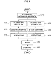
- FIG. 4 is a flowchart showing an example of mixing ultrasound images filtered by filters with different filtering masks.
- FIG. 1 is a block diagram of an illustrative embodiment of an ultrasound imaging device.
- a probe 100 may include a plurality of elements 112.
- the elements 112 may transmit ultrasound signals along scan lines set in a target object in response to transmit pulse signals applied thereto.
- the elements 112 may then output electrical receive signals based on ultrasound echoes reflected from the target object.
- a data acquiring unit 120 may perform signal processing upon the receive signals to thereby form ultrasound image data.
- the ultrasound image data may include a 3-dimensional ultrasound image data such as volume data, as illustrated in FIG. 2 .
- Reference planes A, B and C may be set in the volume data.
- the reference planes A, B and C may be determined based on a scanning direction.
- a resolution of reference plane images may depend on the amount of ultrasound image data, which are acquired during the scanning. Generally, a larger amount of ultrasound image data may be acquired in the order of an axial direction, a lateral direction and an elevation direction.
- a filtering unit 130 may filter the ultrasound image data to reduce speckle noises in the ultrasound image data.
- the filtering unit 130 may adopt an adaptive 3-dimensional filter.
- the adaptive 3-dimensional filter may use a filtering mask, the size of which is determined according to a data acquisition ratio of the ultrasound image data in data acquisition directions.
- the filter unit 130 may calculate a data acquisition ratio of amounts of the ultrasound image data in axial, lateral and elevation directions.
- the filtering unit 130 may determine a size of the filtering mask of the adaptive 3-dimensional filter in the axial, lateral and elevation directions to obtain the same ratio as the data acquisition ratio. For example, assuming that the data acquisition ratio is 7:5:3 in the axial, lateral and elevation directions, the filtering unit 130 may determine the filtering mask having a size of 7 ⁇ 5 ⁇ 3.
- FIG. 3 is a schematic diagram showing an example of a filtering mask set on the 3-dimensional ultrasound image data 300.
- a length of the filtering mask 310 in an axial direction for which a relatively more amount of ultrasound image data may be obtained, may be set to be relatively long.
- a length of the filtering mask 310 in an elevation direction for which a relatively less amount of ultrasound image data may be obtained, may be set to be relatively short.
- the filter may be an average filter or a Gaussian filter. That is, the filtering unit 130 may be configured to smooth the ultrasound image through the filtering to thereby reduce the speckle noises.
- a user input unit 140 may receive an instruction from a user.
- the user input unit 140 may be an input device such as a keyboard, a mouse, a track ball and the like.
- the size of the filtering mask may be determined according to the amount of the ultrasound data for the respective data acquisition directions in accordance with one embodiment. Also, in another embodiment, the size of the filtering mask may be determined by the instruction inputted through the user input unit 140. That is, the user may adjust the size of the filtering mask so that a desirable ultrasound image may be obtained.
- the scan converting unit 150 may scan-convert the filtered ultrasound image data into a data format suitable for display.
- the scan converting unit 150 may perform 3-dimensional scan conversion.
- a 3-dimensional rendering unit 160 may perform volume rendering upon the scan-converted ultrasound image data to thereby form a 3-dimensional ultrasound image.
- the volume rendering may be carried out with a ray casting method.
- the 3-dimensional ultrasound image data obtained through the volume rendering may be interpolated to form a 3-dimensional ultrasound image.
- the 3-dimensional ultrasound image may be displayed on a display unit (not shown).
- the 3-dimensional ultrasound image data may be filtered at least twice with the filtering masks having different sizes.
- the filtered 3-dimensional ultrasound image data may be scan-converted and rendered. This is so that a plurality of 3-dimensional ultrasound images obtained by using different filtering masks may be obtained.
- the plurality of 3-dimensional ultrasound images may be mixed to obtain a desirably smoothened 3-dimensional ultrasound image.
- the ultrasound imaging device 100 may further comprise a mixing unit 170 for mixing the 3-dimensional ultrasound images produced by the 3-dimensional rendering unit 160.
- FIG. 4 is a flowchart showing a procedure of forming an ultrasound image by mixing ultrasound images filtered with different sizes of the filtering masks.
- the data acquiring unit 120 may acquire the ultrasound image data based on the receive signals outputted from the probe 110.
- the filtering unit 130 may filter the ultrasound image data with a first filtering mask to thereby output a first filtered ultrasound image data at step S420.
- the size of the first filtering mask may be determined according to a ratio of amounts of the ultrasound image data in the axial, lateral and elevation directions. That is, the size of the first filtering mask may be determined to have the same ratio as the data acquisition ratio in the axial, lateral and elevation directions.
- the size of the filtering mask may be determined by the user instruction inputted through the user input unit 140.
- the scan converting unit 150 may scan-convert the first filtered ultrasound image data to output a first scan-converted ultrasound image data at step S430.
- the 3-dimensional rendering unit 160 may perform the volume rendering upon the first scan-converted ultrasound image data to thereby form a first ultrasound image data at step S440.
- the filtering unit 130 may filter the ultrasound image data with a second filtering mask to thereby output a second filtered ultrasound image data at step S450.
- the size of the filtering mask may be determined to have a larger size than the first filtering mask.
- the size of the second mark filter may also be determined to have the same ratio as the data acquisition ratio in the axial, lateral and elevation directions.
- the size of the second filtering mask may be determined by the user instruction inputted through the user input unit 140.
- the scan converting unit 150 may scan-convert the second filtered ultrasound image data to output a second scan-converted ultrasound image data at step S460.
- the 3-dimensional rendering unit 160 may perform the volume rendering upon the second scan-converted ultrasound image data to thereby form a second ultrasound image at step S470.
- the mixing unit 170 may mix the first and second ultrasound images to thereby form a final 3-dimensional ultrasound image at step S480.
- a mixing ratio of the first and second ultrasound images may be determined by a user instruction inputted through the user input unit 140. For example, if the mixing ratio of the first ultrasound image is higher, then a relatively sharper ultrasound image may be obtained. Also, if the mixing ratio of the second ultrasound image is higher, then a relatively more smoothened ultrasound image may be obtained.
- the mixed 3-dimensional ultrasound image may be displayed through the display unit at step S490. According to another embodiment, the more smoothened 3-dimensional ultrasound image may be obtained.
- the size of the filtering mask is adaptively adjusted according to the data acquisition ratio in the axial, lateral and elevation directions, the data loss may be reduced with a reduction of the speckle noise.
- an enhanced 3-dimensional ultrasound image may be obtained.
- filtering calculation may be reduced.
- an ultrasound imaging device comprising: a data acquiring unit for acquiring 3-dimensional ultrasound image data based on receive signals formed based on ultrasound echoes reflected from a target object; a filtering unit for determining a size of a filtering mask of a filter, said size being adaptively determined according to an amount of the 3-dimensional ultrasound image data in data acquisition directions, the filtering unit being further configured to filter the 3-dimensional ultrasound image data by using the filtering mask; a scan converting unit for scan-converting the filtered 3-dimensional ultrasound image data; and a 3-dimensional rendering unit for performing 3-dimensional rendering upon the scan-converted 3-dimensional ultrasound image data to form a 3-dimensional ultrasound image.
- a method of forming an ultrasound image comprising: a) acquiring 3-dimensional ultrasound image data based on ultrasound echoes reflected from a target object; b) adaptively determining a size of a filtering mask of a filter according to an amount of the 3-dimensional ultrasound image data in data acquisition directions and filtering the 3-dimensional ultrasound image data by using the filtering mask; c) scan-converting the filtered 3-dimensional ultrasound image data; and d) performing 3-dimensional rendering upon the scan-converted 3-dimensional ultrasound image data to form a 3-dimensional ultrasound image.
- any reference in this specification to "one embodiment,” “an embodiment,” “example embodiment,” etc. means that a particular feature, structure or characteristic described in connection with the embodiment is included in at least one embodiment of the present invention.
- the appearances of such phrases in various places in the specification are not necessarily all referring to the same embodiment.
Landscapes
- Engineering & Computer Science (AREA)
- Physics & Mathematics (AREA)
- Remote Sensing (AREA)
- Radar, Positioning & Navigation (AREA)
- General Physics & Mathematics (AREA)
- Computer Networks & Wireless Communication (AREA)
- Acoustics & Sound (AREA)
- Health & Medical Sciences (AREA)
- Life Sciences & Earth Sciences (AREA)
- Theoretical Computer Science (AREA)
- Radiology & Medical Imaging (AREA)
- Medical Informatics (AREA)
- Surgery (AREA)
- Animal Behavior & Ethology (AREA)
- General Health & Medical Sciences (AREA)
- Public Health (AREA)
- Veterinary Medicine (AREA)
- Molecular Biology (AREA)
- Heart & Thoracic Surgery (AREA)
- Biomedical Technology (AREA)
- Pathology (AREA)
- Nuclear Medicine, Radiotherapy & Molecular Imaging (AREA)
- Biophysics (AREA)
- Ultra Sonic Daignosis Equipment (AREA)
- Image Processing (AREA)
Abstract
Description
- The present application claims priority from Korean Patent Application No.
10-2007-0118600 filed on November 20, 2007 - The present invention generally relates to an ultrasound imaging device, and more particularly to an ultrasound imaging device and a method of forming a 3-dimensional ultrasound image using an adaptive filter.
- An ultrasound imaging device has become an important and popular diagnostic tool due to its non-invasive and non-destructive nature. The ultrasound imaging device may form an ultrasound image by using ultrasound characteristics such as reflection, scattering and absorption when the ultrasound signals are propagated into tissues of a human body. Since the reflection and scattering of the ultrasound signals simultaneously occur in the target object, speckle noises may be included in forming ultrasound image data. The speckle noises may degrade a 3-dimensional ultrasound image. Also, boundaries between the organs and a background, which are important portions for diagnosis, may not be correctly displayed due to the speckle noises. Thus, the speckle noises may be burdensome in analyzing the 3-dimensional ultrasound image and examining the organs in the 3-dimensional ultrasound image.
- Recently, various types of filters have been introduced to reduce the speckle noises in the 3-dimensional ultrasound image. However, the conventional filters may filter the 3-dimensional ultrasound data without considering an amount of data in data acquisition directions (i.e., axial, lateral and elevation directions) to reduce the speckle noises. As such, a loss of the ultrasound image data may occur during the filtering. Thus, the 3-dimensional ultrasound image may be distorted due to the data loss.
-
FIG. 1 is a block diagram showing one embodiment of the ultrasound imaging device. -
FIG. 2 is a schematic diagram showing an example of 3-dimensional ultrasound image data acquired in axial, lateral and elevation directions. -
FIG. 3 is a schematic diagram showing an example of a filtering mask set in 3-dimensional ultrasound image data. -
FIG. 4 is a flowchart showing an example of mixing ultrasound images filtered by filters with different filtering masks. -
FIG. 1 is a block diagram of an illustrative embodiment of an ultrasound imaging device. Referring toFIG. 1 , a probe 100 may include a plurality ofelements 112. Theelements 112 may transmit ultrasound signals along scan lines set in a target object in response to transmit pulse signals applied thereto. Theelements 112 may then output electrical receive signals based on ultrasound echoes reflected from the target object. - A
data acquiring unit 120 may perform signal processing upon the receive signals to thereby form ultrasound image data. The ultrasound image data may include a 3-dimensional ultrasound image data such as volume data, as illustrated inFIG. 2 . Reference planes A, B and C may be set in the volume data. The reference planes A, B and C may be determined based on a scanning direction. A resolution of reference plane images may depend on the amount of ultrasound image data, which are acquired during the scanning. Generally, a larger amount of ultrasound image data may be acquired in the order of an axial direction, a lateral direction and an elevation direction. - A
filtering unit 130 may filter the ultrasound image data to reduce speckle noises in the ultrasound image data. In one embodiment, thefiltering unit 130 may adopt an adaptive 3-dimensional filter. The adaptive 3-dimensional filter may use a filtering mask, the size of which is determined according to a data acquisition ratio of the ultrasound image data in data acquisition directions. Thefilter unit 130 may calculate a data acquisition ratio of amounts of the ultrasound image data in axial, lateral and elevation directions. Thefiltering unit 130 may determine a size of the filtering mask of the adaptive 3-dimensional filter in the axial, lateral and elevation directions to obtain the same ratio as the data acquisition ratio. For example, assuming that the data acquisition ratio is 7:5:3 in the axial, lateral and elevation directions, thefiltering unit 130 may determine the filtering mask having a size of 7 × 5 × 3. -
FIG. 3 is a schematic diagram showing an example of a filtering mask set on the 3-dimensionalultrasound image data 300. As shown inFIG. 3 , a length of thefiltering mask 310 in an axial direction, for which a relatively more amount of ultrasound image data may be obtained, may be set to be relatively long. Also, a length of thefiltering mask 310 in an elevation direction, for which a relatively less amount of ultrasound image data may be obtained, may be set to be relatively short. Thus, data loss may be reduced during the filtering. In one embodiment, the filter may be an average filter or a Gaussian filter. That is, thefiltering unit 130 may be configured to smooth the ultrasound image through the filtering to thereby reduce the speckle noises. - A
user input unit 140 may receive an instruction from a user. Theuser input unit 140 may be an input device such as a keyboard, a mouse, a track ball and the like. As mentioned above, the size of the filtering mask may be determined according to the amount of the ultrasound data for the respective data acquisition directions in accordance with one embodiment. Also, in another embodiment, the size of the filtering mask may be determined by the instruction inputted through theuser input unit 140. That is, the user may adjust the size of the filtering mask so that a desirable ultrasound image may be obtained. - The
scan converting unit 150 may scan-convert the filtered ultrasound image data into a data format suitable for display. Thescan converting unit 150 may perform 3-dimensional scan conversion. A 3-dimensional rendering unit 160 may perform volume rendering upon the scan-converted ultrasound image data to thereby form a 3-dimensional ultrasound image. The volume rendering may be carried out with a ray casting method. The 3-dimensional ultrasound image data obtained through the volume rendering may be interpolated to form a 3-dimensional ultrasound image. The 3-dimensional ultrasound image may be displayed on a display unit (not shown). - In another embodiment, the 3-dimensional ultrasound image data may be filtered at least twice with the filtering masks having different sizes. The filtered 3-dimensional ultrasound image data may be scan-converted and rendered. This is so that a plurality of 3-dimensional ultrasound images obtained by using different filtering masks may be obtained. The plurality of 3-dimensional ultrasound images may be mixed to obtain a desirably smoothened 3-dimensional ultrasound image. To this end, the ultrasound imaging device 100 may further comprise a
mixing unit 170 for mixing the 3-dimensional ultrasound images produced by the 3-dimensional rendering unit 160. -
FIG. 4 is a flowchart showing a procedure of forming an ultrasound image by mixing ultrasound images filtered with different sizes of the filtering masks. Referring toFIG. 4 , thedata acquiring unit 120 may acquire the ultrasound image data based on the receive signals outputted from theprobe 110. Thefiltering unit 130 may filter the ultrasound image data with a first filtering mask to thereby output a first filtered ultrasound image data at step S420. In such a case, the size of the first filtering mask may be determined according to a ratio of amounts of the ultrasound image data in the axial, lateral and elevation directions. That is, the size of the first filtering mask may be determined to have the same ratio as the data acquisition ratio in the axial, lateral and elevation directions. Also, in another embodiment, the size of the filtering mask may be determined by the user instruction inputted through theuser input unit 140. - The
scan converting unit 150 may scan-convert the first filtered ultrasound image data to output a first scan-converted ultrasound image data at step S430. The 3-dimensional rendering unit 160 may perform the volume rendering upon the first scan-converted ultrasound image data to thereby form a first ultrasound image data at step S440. - Subsequently, the
filtering unit 130 may filter the ultrasound image data with a second filtering mask to thereby output a second filtered ultrasound image data at step S450. In such a case, the size of the filtering mask may be determined to have a larger size than the first filtering mask. The size of the second mark filter may also be determined to have the same ratio as the data acquisition ratio in the axial, lateral and elevation directions. Moreover, the size of the second filtering mask may be determined by the user instruction inputted through theuser input unit 140. - The
scan converting unit 150 may scan-convert the second filtered ultrasound image data to output a second scan-converted ultrasound image data at step S460. The 3-dimensional rendering unit 160 may perform the volume rendering upon the second scan-converted ultrasound image data to thereby form a second ultrasound image at step S470. - The
mixing unit 170 may mix the first and second ultrasound images to thereby form a final 3-dimensional ultrasound image at step S480. A mixing ratio of the first and second ultrasound images may be determined by a user instruction inputted through theuser input unit 140. For example, if the mixing ratio of the first ultrasound image is higher, then a relatively sharper ultrasound image may be obtained. Also, if the mixing ratio of the second ultrasound image is higher, then a relatively more smoothened ultrasound image may be obtained. The mixed 3-dimensional ultrasound image may be displayed through the display unit at step S490. According to another embodiment, the more smoothened 3-dimensional ultrasound image may be obtained. - As mentioned above, since the size of the filtering mask is adaptively adjusted according to the data acquisition ratio in the axial, lateral and elevation directions, the data loss may be reduced with a reduction of the speckle noise. Thus, an enhanced 3-dimensional ultrasound image may be obtained. Further, as the adaptive filtering mask is adopted, filtering calculation may be reduced.
- In accordance with one embodiment of the present invention, there is provided an ultrasound imaging device, comprising: a data acquiring unit for acquiring 3-dimensional ultrasound image data based on receive signals formed based on ultrasound echoes reflected from a target object; a filtering unit for determining a size of a filtering mask of a filter, said size being adaptively determined according to an amount of the 3-dimensional ultrasound image data in data acquisition directions, the filtering unit being further configured to filter the 3-dimensional ultrasound image data by using the filtering mask; a scan converting unit for scan-converting the filtered 3-dimensional ultrasound image data; and a 3-dimensional rendering unit for performing 3-dimensional rendering upon the scan-converted 3-dimensional ultrasound image data to form a 3-dimensional ultrasound image.
- In accordance with another embodiment of the present invention, there is provided a method of forming an ultrasound image, comprising: a) acquiring 3-dimensional ultrasound image data based on ultrasound echoes reflected from a target object; b) adaptively determining a size of a filtering mask of a filter according to an amount of the 3-dimensional ultrasound image data in data acquisition directions and filtering the 3-dimensional ultrasound image data by using the filtering mask; c) scan-converting the filtered 3-dimensional ultrasound image data; and d) performing 3-dimensional rendering upon the scan-converted 3-dimensional ultrasound image data to form a 3-dimensional ultrasound image.
- Any reference in this specification to "one embodiment," "an embodiment," "example embodiment," etc. means that a particular feature, structure or characteristic described in connection with the embodiment is included in at least one embodiment of the present invention. The appearances of such phrases in various places in the specification are not necessarily all referring to the same embodiment. Further, when a particular feature, structure or characteristic is described in connection with any embodiment, it is submitted that it is within the purview of one skilled in the art to effect such feature, structure or characteristic in connection with other ones of the embodiments.
- Although embodiments have been described with reference to a number of illustrative embodiments thereof, it should be understood that numerous other modifications and embodiments can be devised by those skilled in the art that will fall within the spirit and scope of the principles of this disclosure. More particularly, numerous variations and modifications are possible in the component parts and/or arrangements of the subject combination arrangement within the scope of the disclosure, the drawings and the appended claims. In addition to variations and modifications in the component parts and/or arrangements, alternative uses will also be apparent to those skilled in the art.
Claims (12)
- An ultrasound imaging device, comprising:a data acquiring unit for acquiring 3-dimensional ultrasound image data based on receive signals formed based on ultrasound echoes reflected from a target object;a filtering unit for determining a size of a filtering mask of a filter, said size being adaptively determined according to an amount of the 3-dimensional ultrasound image data in data acquisition directions, the filtering unit being further configured to filter the 3-dimensional ultrasound image data by using the filtering mask;a scan converting unit for scan-converting the filtered 3-dimensional ultrasound image data; anda 3-dimensional rendering unit for performing 3-dimensional rendering upon the scan-converted 3-dimensional ultrasound image data to form a 3-dimensional ultrasound image.
- The ultrasound imaging device of Claim 1, wherein the filtering unit determines the size of the filtering mask according to a data acquisition ratio of an amount of the 3-dimensional data in data acquisition directions.
- The ultrasound imaging device of Claim 1, further comprising a user input unit operable to an instruction for setting the size of the filtering mask.
- The ultrasound imaging device of Claim 2, wherein the size of the filtering mask is determined to have different lengths in at least two acquisition directions.
- The ultrasound imaging device of Claim 1, further comprising a mixing unit for mixing a plurality of ultrasound images.
- The ultrasound imaging device of Claim 5, wherein the filtering unit filters the 3-dimensional ultrasound image data with a first filtering mask to thereby output a first filtered ultrasound image data and a second filtering mask having a different size from the first filtering mask to thereby output a second filtered ultrasound image data, the scan converting unit scan-converts the first and second filtered ultrasound image data to output first and second scan-converted ultrasound image data, the 3-dimensional rendering unit performs rendering upon the first and second scan-converted ultrasound image data to thereby form first and second 3-dimensional ultrasound images, and the mixing unit mixes the first and second 3-dimensional ultrasound images to form a single 3-dimensional ultrasound image.
- The ultrasound imaging device of Claim 6, wherein the second filtering mask is larger than the first filtering mask.
- A method of forming an ultrasound image, comprising:a) acquiring 3-dimensional ultrasound image data based on ultrasound echoes reflected from a target object;b) adaptively determining a size of a filtering mask of a filter according to an amount of the 3-dimensional ultrasound image data in data acquisition directions and filtering the 3-dimensional ultrasound image data by using the filtering mask;c) scan-converting the filtered 3-dimensional ultrasound image data; andd) performing 3-dimensional rendering upon the scan-converted 3-dimensional ultrasound image data to form a 3-dimensional ultrasound image.
- The method of Claim 8, wherein the size of the filtering mask is determined according to a ratio of amount of the 3-dimensional data in data acquisition directions.
- The method of Claim 9, wherein the size of the filtering mask is determined to have a different length in at least two acquisition directions.
- The method of Claim 10, wherein the step b) includes filtering the 3-dimensional ultrasound image data with a first filtering mask to thereby output a first filtered ultrasound image data and a second filtering mask having a different size from the first filtering mask to thereby output a second filtered ultrasound image data, the step c) includes scan-converting the first and second filtered ultrasound image data to output first and second scan-converted ultrasound image data, and the step d) includes performing rendering upon the first and second scan-converted ultrasound image data to thereby form first and second 3-dimensional ultrasound images, the method further comprising mixing the first and second 3-dimensional ultrasound images to form a single 3-dimensional ultrasound image.
- The method of Claim 11, wherein the second filtering mask is larger than the first filtering mask.
Applications Claiming Priority (1)
| Application Number | Priority Date | Filing Date | Title |
|---|---|---|---|
| KR1020070118600A KR101051555B1 (en) | 2007-11-20 | 2007-11-20 | Ultrasonic Imaging Apparatus and Method for Forming an Improved 3D Ultrasound Image |
Publications (3)
| Publication Number | Publication Date |
|---|---|
| EP2063290A2 true EP2063290A2 (en) | 2009-05-27 |
| EP2063290A3 EP2063290A3 (en) | 2012-05-30 |
| EP2063290B1 EP2063290B1 (en) | 2016-06-15 |
Family
ID=40361753
Family Applications (1)
| Application Number | Title | Priority Date | Filing Date |
|---|---|---|---|
| EP08020149.4A Not-in-force EP2063290B1 (en) | 2007-11-20 | 2008-11-19 | Adaptive image filtering in an ultrasound imaging device |
Country Status (4)
| Country | Link |
|---|---|
| US (1) | US8282552B2 (en) |
| EP (1) | EP2063290B1 (en) |
| JP (1) | JP5264435B2 (en) |
| KR (1) | KR101051555B1 (en) |
Cited By (1)
| Publication number | Priority date | Publication date | Assignee | Title |
|---|---|---|---|---|
| EP2180339A1 (en) * | 2008-10-21 | 2010-04-28 | Medison Co., Ltd. | Doppler signal processing for an enhanced spectral doppler image |
Families Citing this family (8)
| Publication number | Priority date | Publication date | Assignee | Title |
|---|---|---|---|---|
| KR101124759B1 (en) | 2009-11-17 | 2012-03-23 | 삼성메디슨 주식회사 | Ultrasound system and method for enhancing quality of ultrasound image based on entropy information |
| US8839672B2 (en) * | 2010-10-19 | 2014-09-23 | Board Of Regents, The University Of Texas System | Combined ultrasound and photoacoustic imaging of metal objects |
| US20120245465A1 (en) * | 2011-03-25 | 2012-09-27 | Joger Hansegard | Method and system for displaying intersection information on a volumetric ultrasound image |
| KR101786008B1 (en) * | 2011-04-15 | 2017-10-16 | 알피니언메디칼시스템 주식회사 | Ultrasonic Therapeutic Apparatus by Using Motion Tracking And Method therefor |
| KR20140114523A (en) * | 2013-03-15 | 2014-09-29 | 삼성전자주식회사 | Method and apparatus for processing ultrasound data by using scan line information |
| US20150025666A1 (en) * | 2013-07-16 | 2015-01-22 | Children's National Medical Center | Three dimensional printed replicas of patient's anatomy for medical applications |
| US10846569B2 (en) * | 2018-11-09 | 2020-11-24 | General Electric Company | Method and systems for scan conversion with higher resolution |
| FR3127619B1 (en) | 2021-09-27 | 2024-05-31 | Module Me | Electrical interconnection module for electric instrument body connectable to a removable microphone module |
Citations (3)
| Publication number | Priority date | Publication date | Assignee | Title |
|---|---|---|---|---|
| US5050226A (en) | 1989-03-24 | 1991-09-17 | U.S. Philips Corporation | Ultrasonic echographic imaging device utilizing an improved adaptive filter |
| US6468218B1 (en) | 2001-08-31 | 2002-10-22 | Siemens Medical Systems, Inc. | 3-D ultrasound imaging system and method |
| US20030097068A1 (en) | 1998-06-02 | 2003-05-22 | Acuson Corporation | Medical diagnostic ultrasound system and method for versatile processing |
Family Cites Families (17)
| Publication number | Priority date | Publication date | Assignee | Title |
|---|---|---|---|---|
| JP2936085B2 (en) | 1991-11-19 | 1999-08-23 | 富士写真フイルム株式会社 | Image data processing method and apparatus |
| US5999639A (en) * | 1997-09-04 | 1999-12-07 | Qualia Computing, Inc. | Method and system for automated detection of clustered microcalcifications from digital mammograms |
| US7308126B2 (en) * | 1997-08-28 | 2007-12-11 | Icad, Inc. | Use of computer-aided detection system outputs in clinical practice |
| US6137898A (en) * | 1997-08-28 | 2000-10-24 | Qualia Computing, Inc. | Gabor filtering for improved microcalcification detection in digital mammograms |
| US6970587B1 (en) * | 1997-08-28 | 2005-11-29 | Icad, Inc. | Use of computer-aided detection system outputs in clinical practice |
| DE60115314T2 (en) * | 2000-04-18 | 2006-08-03 | The University Of Hong Kong | Method for the evaluation of images for defect detection |
| JP2001340338A (en) * | 2000-06-05 | 2001-12-11 | Olympus Optical Co Ltd | Ultrasonic diagnosing device |
| US7556602B2 (en) * | 2000-11-24 | 2009-07-07 | U-Systems, Inc. | Breast cancer screening with adjunctive ultrasound mammography |
| JP2004283490A (en) * | 2003-03-25 | 2004-10-14 | Fuji Photo Film Co Ltd | Ultrasonic transmitter-receiver |
| WO2005036451A1 (en) * | 2003-10-08 | 2005-04-21 | Lifespan Biosciences, Inc. | Automated microspcope slide tissue sample mapping and image acquisition |
| KR100686289B1 (en) * | 2004-04-01 | 2007-02-23 | 주식회사 메디슨 | 3D ultrasound image forming apparatus and method using intra-contour volume data of object image |
| US20050259854A1 (en) * | 2004-05-21 | 2005-11-24 | University Of Chicago | Method for detection of abnormalities in three-dimensional imaging data |
| EP1882450B1 (en) * | 2005-05-19 | 2013-01-02 | Hitachi Medical Corporation | Ultrasonographic device and image processing method thereof |
| US20070083114A1 (en) * | 2005-08-26 | 2007-04-12 | The University Of Connecticut | Systems and methods for image resolution enhancement |
| CN1971616B (en) * | 2005-11-23 | 2012-10-10 | 索诺塞特公司 | Multi-resolution adaptive filtering |
| JP2007268023A (en) * | 2006-03-31 | 2007-10-18 | Chiba Univ | Embolizer observation method and apparatus, and ultrasonic diagnostic apparatus using them |
| CN101448461B (en) * | 2006-05-19 | 2011-04-06 | 株式会社日立医药 | Ultrasonic diagnostic device and boundary extraction method |
-
2007
- 2007-11-20 KR KR1020070118600A patent/KR101051555B1/en not_active Expired - Fee Related
-
2008
- 2008-11-19 US US12/274,269 patent/US8282552B2/en not_active Expired - Fee Related
- 2008-11-19 EP EP08020149.4A patent/EP2063290B1/en not_active Not-in-force
- 2008-11-20 JP JP2008296438A patent/JP5264435B2/en not_active Expired - Fee Related
Patent Citations (3)
| Publication number | Priority date | Publication date | Assignee | Title |
|---|---|---|---|---|
| US5050226A (en) | 1989-03-24 | 1991-09-17 | U.S. Philips Corporation | Ultrasonic echographic imaging device utilizing an improved adaptive filter |
| US20030097068A1 (en) | 1998-06-02 | 2003-05-22 | Acuson Corporation | Medical diagnostic ultrasound system and method for versatile processing |
| US6468218B1 (en) | 2001-08-31 | 2002-10-22 | Siemens Medical Systems, Inc. | 3-D ultrasound imaging system and method |
Cited By (1)
| Publication number | Priority date | Publication date | Assignee | Title |
|---|---|---|---|---|
| EP2180339A1 (en) * | 2008-10-21 | 2010-04-28 | Medison Co., Ltd. | Doppler signal processing for an enhanced spectral doppler image |
Also Published As
| Publication number | Publication date |
|---|---|
| EP2063290B1 (en) | 2016-06-15 |
| US20090131787A1 (en) | 2009-05-21 |
| JP2009125592A (en) | 2009-06-11 |
| US8282552B2 (en) | 2012-10-09 |
| JP5264435B2 (en) | 2013-08-14 |
| EP2063290A3 (en) | 2012-05-30 |
| KR20090052074A (en) | 2009-05-25 |
| KR101051555B1 (en) | 2011-07-22 |
Similar Documents
| Publication | Publication Date | Title |
|---|---|---|
| US8282552B2 (en) | Adaptive image filtering in an ultrasound imaging device | |
| US11238562B2 (en) | Ultrasound system with deep learning network for image artifact identification and removal | |
| US9008383B2 (en) | Enhancing quality of ultrasound image in ultrasound system | |
| US8083680B2 (en) | Ultrasound system and method for forming an ultrasound image | |
| EP1977694A1 (en) | Ultrasound system and method of forming an ultrasound image | |
| US6814703B2 (en) | Apparatus and method for ultrasonic diagnostic imaging using a contrast medium | |
| US20080063305A1 (en) | Apparatus and method for displaying an ultrasound image | |
| JP5948043B2 (en) | Ultrasound system and method for providing color Doppler images based on characteristic curve information | |
| EP2233945A1 (en) | Surface rendering for volume data in an ultrasound system | |
| EP2339368A2 (en) | Providing multiple 3-dimensional ultrasound images in an ultrasound image | |
| CN101467892A (en) | Ultrasonic diagnostic apparatus, ultrasonic image processing apparatus, and ultrasonic image processing method | |
| JP2002034976A (en) | Ultrasonic diagnostic apparatus and ultrasonic imaging method | |
| US8348848B1 (en) | Methods and apparatus for ultrasound imaging | |
| EP3338641B1 (en) | Ultrasonic diagnostic imaging apparatus | |
| US8157735B2 (en) | Ultrasound system and method of providing ultrasound images | |
| EP2196151A1 (en) | Ultrasound system and method for forming a plurality of three-dimensional ultrasound images | |
| EP2034332A2 (en) | Ultrasound system and method of forming a 3D ultrasound image indicating colour flow changes with respect to a reference velocity | |
| JP4426472B2 (en) | Ultrasonic diagnostic equipment | |
| EP2251831A2 (en) | Ultrasound system and method for rendering volume data | |
| JP4851078B2 (en) | Ultrasound imaging device | |
| JP5936857B2 (en) | Ultrasonic diagnostic apparatus and image processing program thereof | |
| KR100842017B1 (en) | Image processing system and method for controlling image magnification | |
| KR100656861B1 (en) | Image Processing System and Method for Rendering Volume Data | |
| JP2001327496A (en) | Ultrasonic diagnosing system | |
| KR101055528B1 (en) | Ultrasound system and method for providing OH |
Legal Events
| Date | Code | Title | Description |
|---|---|---|---|
| PUAI | Public reference made under article 153(3) epc to a published international application that has entered the european phase |
Free format text: ORIGINAL CODE: 0009012 |
|
| AK | Designated contracting states |
Kind code of ref document: A2 Designated state(s): AT BE BG CH CY CZ DE DK EE ES FI FR GB GR HR HU IE IS IT LI LT LU LV MC MT NL NO PL PT RO SE SI SK TR |
|
| AX | Request for extension of the european patent |
Extension state: AL BA MK RS |
|
| PUAL | Search report despatched |
Free format text: ORIGINAL CODE: 0009013 |
|
| AK | Designated contracting states |
Kind code of ref document: A3 Designated state(s): AT BE BG CH CY CZ DE DK EE ES FI FR GB GR HR HU IE IS IT LI LT LU LV MC MT NL NO PL PT RO SE SI SK TR |
|
| AX | Request for extension of the european patent |
Extension state: AL BA MK RS |
|
| RIC1 | Information provided on ipc code assigned before grant |
Ipc: G06T 5/20 20060101ALI20120423BHEP Ipc: G01S 7/52 20060101ALI20120423BHEP Ipc: G01S 15/89 20060101AFI20120423BHEP |
|
| 17P | Request for examination filed |
Effective date: 20121130 |
|
| AKX | Designation fees paid |
Designated state(s): AT BE BG CH CY CZ DE DK EE ES FI FR GB GR HR HU IE IS IT LI LT LU LV MC MT NL NO PL PT RO SE SI SK TR |
|
| 17Q | First examination report despatched |
Effective date: 20130318 |
|
| REG | Reference to a national code |
Ref country code: DE Ref legal event code: R079 Ref document number: 602008044691 Country of ref document: DE Free format text: PREVIOUS MAIN CLASS: G01S0015890000 Ipc: A61B0008080000 |
|
| GRAP | Despatch of communication of intention to grant a patent |
Free format text: ORIGINAL CODE: EPIDOSNIGR1 |
|
| RIC1 | Information provided on ipc code assigned before grant |
Ipc: G06T 5/50 20060101ALI20160215BHEP Ipc: G01S 15/89 20060101ALI20160215BHEP Ipc: G01S 7/52 20060101ALI20160215BHEP Ipc: A61B 8/08 20060101AFI20160215BHEP Ipc: A61B 8/14 20060101ALI20160215BHEP Ipc: G06T 5/20 20060101ALI20160215BHEP |
|
| INTG | Intention to grant announced |
Effective date: 20160302 |
|
| GRAS | Grant fee paid |
Free format text: ORIGINAL CODE: EPIDOSNIGR3 |
|
| GRAA | (expected) grant |
Free format text: ORIGINAL CODE: 0009210 |
|
| RAP1 | Party data changed (applicant data changed or rights of an application transferred) |
Owner name: SAMSUNG MEDISON CO., LTD. |
|
| AK | Designated contracting states |
Kind code of ref document: B1 Designated state(s): AT BE BG CH CY CZ DE DK EE ES FI FR GB GR HR HU IE IS IT LI LT LU LV MC MT NL NO PL PT RO SE SI SK TR |
|
| REG | Reference to a national code |
Ref country code: CH Ref legal event code: EP Ref country code: GB Ref legal event code: FG4D |
|
| REG | Reference to a national code |
Ref country code: IE Ref legal event code: FG4D |
|
| REG | Reference to a national code |
Ref country code: AT Ref legal event code: REF Ref document number: 806077 Country of ref document: AT Kind code of ref document: T Effective date: 20160715 |
|
| REG | Reference to a national code |
Ref country code: DE Ref legal event code: R096 Ref document number: 602008044691 Country of ref document: DE |
|
| REG | Reference to a national code |
Ref country code: NL Ref legal event code: FP |
|
| REG | Reference to a national code |
Ref country code: LT Ref legal event code: MG4D |
|
| PG25 | Lapsed in a contracting state [announced via postgrant information from national office to epo] |
Ref country code: FI Free format text: LAPSE BECAUSE OF FAILURE TO SUBMIT A TRANSLATION OF THE DESCRIPTION OR TO PAY THE FEE WITHIN THE PRESCRIBED TIME-LIMIT Effective date: 20160615 Ref country code: LT Free format text: LAPSE BECAUSE OF FAILURE TO SUBMIT A TRANSLATION OF THE DESCRIPTION OR TO PAY THE FEE WITHIN THE PRESCRIBED TIME-LIMIT Effective date: 20160615 Ref country code: NO Free format text: LAPSE BECAUSE OF FAILURE TO SUBMIT A TRANSLATION OF THE DESCRIPTION OR TO PAY THE FEE WITHIN THE PRESCRIBED TIME-LIMIT Effective date: 20160915 |
|
| REG | Reference to a national code |
Ref country code: FR Ref legal event code: PLFP Year of fee payment: 9 |
|
| REG | Reference to a national code |
Ref country code: AT Ref legal event code: MK05 Ref document number: 806077 Country of ref document: AT Kind code of ref document: T Effective date: 20160615 |
|
| PG25 | Lapsed in a contracting state [announced via postgrant information from national office to epo] |
Ref country code: HR Free format text: LAPSE BECAUSE OF FAILURE TO SUBMIT A TRANSLATION OF THE DESCRIPTION OR TO PAY THE FEE WITHIN THE PRESCRIBED TIME-LIMIT Effective date: 20160615 Ref country code: GR Free format text: LAPSE BECAUSE OF FAILURE TO SUBMIT A TRANSLATION OF THE DESCRIPTION OR TO PAY THE FEE WITHIN THE PRESCRIBED TIME-LIMIT Effective date: 20160916 Ref country code: LV Free format text: LAPSE BECAUSE OF FAILURE TO SUBMIT A TRANSLATION OF THE DESCRIPTION OR TO PAY THE FEE WITHIN THE PRESCRIBED TIME-LIMIT Effective date: 20160615 Ref country code: SE Free format text: LAPSE BECAUSE OF FAILURE TO SUBMIT A TRANSLATION OF THE DESCRIPTION OR TO PAY THE FEE WITHIN THE PRESCRIBED TIME-LIMIT Effective date: 20160615 |
|
| PG25 | Lapsed in a contracting state [announced via postgrant information from national office to epo] |
Ref country code: IS Free format text: LAPSE BECAUSE OF FAILURE TO SUBMIT A TRANSLATION OF THE DESCRIPTION OR TO PAY THE FEE WITHIN THE PRESCRIBED TIME-LIMIT Effective date: 20161015 Ref country code: SK Free format text: LAPSE BECAUSE OF FAILURE TO SUBMIT A TRANSLATION OF THE DESCRIPTION OR TO PAY THE FEE WITHIN THE PRESCRIBED TIME-LIMIT Effective date: 20160615 Ref country code: CZ Free format text: LAPSE BECAUSE OF FAILURE TO SUBMIT A TRANSLATION OF THE DESCRIPTION OR TO PAY THE FEE WITHIN THE PRESCRIBED TIME-LIMIT Effective date: 20160615 Ref country code: EE Free format text: LAPSE BECAUSE OF FAILURE TO SUBMIT A TRANSLATION OF THE DESCRIPTION OR TO PAY THE FEE WITHIN THE PRESCRIBED TIME-LIMIT Effective date: 20160615 Ref country code: RO Free format text: LAPSE BECAUSE OF FAILURE TO SUBMIT A TRANSLATION OF THE DESCRIPTION OR TO PAY THE FEE WITHIN THE PRESCRIBED TIME-LIMIT Effective date: 20160615 |
|
| PG25 | Lapsed in a contracting state [announced via postgrant information from national office to epo] |
Ref country code: ES Free format text: LAPSE BECAUSE OF FAILURE TO SUBMIT A TRANSLATION OF THE DESCRIPTION OR TO PAY THE FEE WITHIN THE PRESCRIBED TIME-LIMIT Effective date: 20160615 Ref country code: PT Free format text: LAPSE BECAUSE OF FAILURE TO SUBMIT A TRANSLATION OF THE DESCRIPTION OR TO PAY THE FEE WITHIN THE PRESCRIBED TIME-LIMIT Effective date: 20161017 Ref country code: PL Free format text: LAPSE BECAUSE OF FAILURE TO SUBMIT A TRANSLATION OF THE DESCRIPTION OR TO PAY THE FEE WITHIN THE PRESCRIBED TIME-LIMIT Effective date: 20160615 Ref country code: AT Free format text: LAPSE BECAUSE OF FAILURE TO SUBMIT A TRANSLATION OF THE DESCRIPTION OR TO PAY THE FEE WITHIN THE PRESCRIBED TIME-LIMIT Effective date: 20160615 Ref country code: BE Free format text: LAPSE BECAUSE OF FAILURE TO SUBMIT A TRANSLATION OF THE DESCRIPTION OR TO PAY THE FEE WITHIN THE PRESCRIBED TIME-LIMIT Effective date: 20160615 |
|
| REG | Reference to a national code |
Ref country code: DE Ref legal event code: R097 Ref document number: 602008044691 Country of ref document: DE |
|
| PLBE | No opposition filed within time limit |
Free format text: ORIGINAL CODE: 0009261 |
|
| STAA | Information on the status of an ep patent application or granted ep patent |
Free format text: STATUS: NO OPPOSITION FILED WITHIN TIME LIMIT |
|
| 26N | No opposition filed |
Effective date: 20170316 |
|
| PG25 | Lapsed in a contracting state [announced via postgrant information from national office to epo] |
Ref country code: DK Free format text: LAPSE BECAUSE OF FAILURE TO SUBMIT A TRANSLATION OF THE DESCRIPTION OR TO PAY THE FEE WITHIN THE PRESCRIBED TIME-LIMIT Effective date: 20160615 |
|
| REG | Reference to a national code |
Ref country code: CH Ref legal event code: PL |
|
| GBPC | Gb: european patent ceased through non-payment of renewal fee |
Effective date: 20161119 |
|
| PG25 | Lapsed in a contracting state [announced via postgrant information from national office to epo] |
Ref country code: CH Free format text: LAPSE BECAUSE OF NON-PAYMENT OF DUE FEES Effective date: 20161130 Ref country code: LI Free format text: LAPSE BECAUSE OF NON-PAYMENT OF DUE FEES Effective date: 20161130 |
|
| REG | Reference to a national code |
Ref country code: IE Ref legal event code: MM4A |
|
| PG25 | Lapsed in a contracting state [announced via postgrant information from national office to epo] |
Ref country code: SI Free format text: LAPSE BECAUSE OF FAILURE TO SUBMIT A TRANSLATION OF THE DESCRIPTION OR TO PAY THE FEE WITHIN THE PRESCRIBED TIME-LIMIT Effective date: 20160615 |
|
| PG25 | Lapsed in a contracting state [announced via postgrant information from national office to epo] |
Ref country code: LU Free format text: LAPSE BECAUSE OF NON-PAYMENT OF DUE FEES Effective date: 20161130 |
|
| REG | Reference to a national code |
Ref country code: FR Ref legal event code: PLFP Year of fee payment: 10 |
|
| PG25 | Lapsed in a contracting state [announced via postgrant information from national office to epo] |
Ref country code: GB Free format text: LAPSE BECAUSE OF NON-PAYMENT OF DUE FEES Effective date: 20161119 Ref country code: IE Free format text: LAPSE BECAUSE OF NON-PAYMENT OF DUE FEES Effective date: 20161119 |
|
| PG25 | Lapsed in a contracting state [announced via postgrant information from national office to epo] |
Ref country code: HU Free format text: LAPSE BECAUSE OF FAILURE TO SUBMIT A TRANSLATION OF THE DESCRIPTION OR TO PAY THE FEE WITHIN THE PRESCRIBED TIME-LIMIT; INVALID AB INITIO Effective date: 20081119 Ref country code: CY Free format text: LAPSE BECAUSE OF FAILURE TO SUBMIT A TRANSLATION OF THE DESCRIPTION OR TO PAY THE FEE WITHIN THE PRESCRIBED TIME-LIMIT Effective date: 20160615 |
|
| PG25 | Lapsed in a contracting state [announced via postgrant information from national office to epo] |
Ref country code: MC Free format text: LAPSE BECAUSE OF FAILURE TO SUBMIT A TRANSLATION OF THE DESCRIPTION OR TO PAY THE FEE WITHIN THE PRESCRIBED TIME-LIMIT Effective date: 20160615 Ref country code: TR Free format text: LAPSE BECAUSE OF FAILURE TO SUBMIT A TRANSLATION OF THE DESCRIPTION OR TO PAY THE FEE WITHIN THE PRESCRIBED TIME-LIMIT Effective date: 20160615 |
|
| PG25 | Lapsed in a contracting state [announced via postgrant information from national office to epo] |
Ref country code: BG Free format text: LAPSE BECAUSE OF FAILURE TO SUBMIT A TRANSLATION OF THE DESCRIPTION OR TO PAY THE FEE WITHIN THE PRESCRIBED TIME-LIMIT Effective date: 20160615 |
|
| PG25 | Lapsed in a contracting state [announced via postgrant information from national office to epo] |
Ref country code: MT Free format text: LAPSE BECAUSE OF NON-PAYMENT OF DUE FEES Effective date: 20161119 |
|
| REG | Reference to a national code |
Ref country code: FR Ref legal event code: PLFP Year of fee payment: 11 |
|
| PGFP | Annual fee paid to national office [announced via postgrant information from national office to epo] |
Ref country code: NL Payment date: 20181008 Year of fee payment: 11 |
|
| PGFP | Annual fee paid to national office [announced via postgrant information from national office to epo] |
Ref country code: DE Payment date: 20181005 Year of fee payment: 11 |
|
| PGFP | Annual fee paid to national office [announced via postgrant information from national office to epo] |
Ref country code: FR Payment date: 20181008 Year of fee payment: 11 Ref country code: IT Payment date: 20181116 Year of fee payment: 11 |
|
| REG | Reference to a national code |
Ref country code: DE Ref legal event code: R119 Ref document number: 602008044691 Country of ref document: DE |
|
| REG | Reference to a national code |
Ref country code: NL Ref legal event code: MM Effective date: 20191201 |
|
| PG25 | Lapsed in a contracting state [announced via postgrant information from national office to epo] |
Ref country code: NL Free format text: LAPSE BECAUSE OF NON-PAYMENT OF DUE FEES Effective date: 20191201 |
|
| PG25 | Lapsed in a contracting state [announced via postgrant information from national office to epo] |
Ref country code: FR Free format text: LAPSE BECAUSE OF NON-PAYMENT OF DUE FEES Effective date: 20191130 Ref country code: IT Free format text: LAPSE BECAUSE OF NON-PAYMENT OF DUE FEES Effective date: 20191119 Ref country code: DE Free format text: LAPSE BECAUSE OF NON-PAYMENT OF DUE FEES Effective date: 20200603 |