EP2063067A1 - Underwater drilling device and method for carrying out underwater drilling, in particular for attaching an underwater anchoring - Google Patents
Underwater drilling device and method for carrying out underwater drilling, in particular for attaching an underwater anchoring Download PDFInfo
- Publication number
- EP2063067A1 EP2063067A1 EP08166074A EP08166074A EP2063067A1 EP 2063067 A1 EP2063067 A1 EP 2063067A1 EP 08166074 A EP08166074 A EP 08166074A EP 08166074 A EP08166074 A EP 08166074A EP 2063067 A1 EP2063067 A1 EP 2063067A1
- Authority
- EP
- European Patent Office
- Prior art keywords
- underwater
- drilling
- seabed
- drilling device
- anchoring
- Prior art date
- Legal status (The legal status is an assumption and is not a legal conclusion. Google has not performed a legal analysis and makes no representation as to the accuracy of the status listed.)
- Granted
Links
Images




Classifications
-
- E—FIXED CONSTRUCTIONS
- E21—EARTH OR ROCK DRILLING; MINING
- E21B—EARTH OR ROCK DRILLING; OBTAINING OIL, GAS, WATER, SOLUBLE OR MELTABLE MATERIALS OR A SLURRY OF MINERALS FROM WELLS
- E21B7/00—Special methods or apparatus for drilling
- E21B7/12—Underwater drilling
- E21B7/124—Underwater drilling with underwater tool drive prime mover, e.g. portable drilling rigs for use on underwater floors
-
- B—PERFORMING OPERATIONS; TRANSPORTING
- B63—SHIPS OR OTHER WATERBORNE VESSELS; RELATED EQUIPMENT
- B63B—SHIPS OR OTHER WATERBORNE VESSELS; EQUIPMENT FOR SHIPPING
- B63B21/00—Tying-up; Shifting, towing, or pushing equipment; Anchoring
- B63B21/24—Anchors
- B63B21/26—Anchors securing to bed
-
- E—FIXED CONSTRUCTIONS
- E21—EARTH OR ROCK DRILLING; MINING
- E21B—EARTH OR ROCK DRILLING; OBTAINING OIL, GAS, WATER, SOLUBLE OR MELTABLE MATERIALS OR A SLURRY OF MINERALS FROM WELLS
- E21B15/00—Supports for the drilling machine, e.g. derricks or masts
- E21B15/02—Supports for the drilling machine, e.g. derricks or masts specially adapted for underwater drilling
Definitions
- the present invention relates to a method for carrying out underwater drilling, which is performed in particular for attaching an underwater anchoring.
- an underwater drilling device is launched.
- the underwater drilling device has a drilling unit which is at least partly positioned within a substantially upwardly closed-off space.
- the underwater drilling device is sunk down to the seabed.
- the underwater drilling device is positioned on the seabed.
- a drill pipe is drilled into the seabed from a starting point on the seabed with the aid of a drilling unit. During the drilling, the course of the drilling is observed.
- a method of this type is known from US 2005/0109537 which discloses an underwater drilling device for carrying out a drilling process.
- the underwater drilling device is launched from a ship with the aid of a hoisting crane, the underwater drilling device being fully submerged underwater and sunk down to the bed of the sea.
- the known underwater drilling device is designed to form a bored well; this commences with the attachment of a foundation guide.
- the underwater drilling device is modular in its construction and has at its centre a well head module which is fastened to the foundation guide.
- the foundation guide serves to anchor the underwater drilling device in soft seabeds.
- the foundation guide can be held vertically or at any desired angle by way of remote-control support points which are provided on the outside of the underwater drilling device.
- the underwater drilling device also has storage compartments for drill pipe parts which can be coupled with the aid of a mast module to the drill pipe which is placed in the seabed, so as to allow long drill pipes to be placed in the seabed.
- the underwater drilling device is connected to the ship with the aid of lines, so that flushing liquids for the drilling can be returned to the ship. Photos are taken with the aid of remote-control underwater vessels and equipment, and acoustic measurements are taken in order to be able to check and if necessary to adjust the drilling process on the bed of the sea.
- a drawback of the known method with the aid of the known underwater drilling device is that the monitoring is limited over the course of the drilling.
- all kinds of base materials rise up and cloud the direct environment of the underwater drilling device. This obscures the drilling process almost entirely.
- the direct environment of the underwater drilling device is further disturbed by the currents which are present above the seabed and the eddies which the drilling entails. These factors impede observation during the drilling. As a result of the poor observation, adequate monitoring of the drilling process is hardly possible and the drilling process is susceptible to interference.
- the object of the present invention is at least partly to overcome at least one of the above-mentioned drawbacks, or else to provide a practicable alternative.
- the invention seeks to provide an underwater drilling device and a method for carrying out underwater drilling, rendering the drilling process less susceptible to interference.
- the method for carrying out underwater drilling according to the invention is particularly suitable for attaching an underwater anchoring.
- the drill pipe used can for example be an anchoring pipe.
- the anchoring pipe is for example a helical anchor, a helix being provided at the distal end of the pipe-shaped anchor.
- an underwater drilling device is launched and sunk down to the seabed.
- the underwater drilling device is positioned on the seabed, so that a drill pipe can be drilled into the seabed from a starting point in the seabed with the aid of a drilling unit of the underwater drilling device.
- the course is observed. The observation can for example be carried out by divers who are present or with the aid of underwater cameras.
- the starting point on the seabed is held substantially in an environment of a gaseous medium.
- the starting point on the seabed is substantially free from water.
- the observation which takes place during the drilling is focused on the starting point on the seabed.
- the course of the drilling can be monitored with the aid of the observation data. For example, slanting withdrawal of the drill pipe, which is visible at the starting point, is an indication of a possibly occurring disturbance.
- the environment of a gaseous medium is an air environment.
- Base materials which rise up during the drilling will not mix with the gaseous environment, so that the view of the starting point is not disturbed.
- the operator has an improved overview of the drilling process. It is for example readily possible for the operator to perceive in the environment of a gaseous medium when a drill pipe is placed at a angle in the seabed or when the drill pipe experiences high resistance in the seabed. As a result of the improved targeted observation in the gaseous environment around the starting point, the operator can intervene more rapidly when the drilling process is not going well. This advantageously prevents disturbances.
- the underwater drilling device is sunk by venting a compartment of the underwater drilling device.
- the compartment used for this purpose is the substantially upwardly closed-off space.
- the underwater drilling device can be launched from a vessel for example with the aid of a hoisting crane, after which at least one compartment of the underwater drilling device fills up with water in a controlled manner. This allows the underwater drilling device to be sunk to the seabed in a reliable manner, wherein the underwater drilling device can disappear completely beneath the surface of the water.
- the underwater device remains connected during the method according to the invention to a control station which is for example provided on a vessel or on the quay in order to operate the underwater drilling device.
- the underwater drilling device is connected to the control station by lines for, for example, discharging and supplying flushing liquids, hardening substances and hydraulic liquids.
- an upwardly closed-off space around the drilling unit is substantially filled with a gaseous medium, before the drilling commences.
- the closed-off space around the drilling unit is preferably made free from water by supplying air from the control station.
- the water located in the closed-off space around the drilling unit will be displaced as a result of the supplying of air, thus producing an air environment around the drilling unit and at the location of the starting point before the drilling on the seabed.
- the method according to the invention can include a step wherein the underwater drilling device is secured to the seabed. This can for example be brought about by providing the underwater drilling device with a ballast, by starting a drive on the outside of the underwater drilling device, which propels the underwater drilling device in the downward direction, or by operating securing members around the underwater drilling device.
- the drill pipe to be placed in the seabed comprises at least two drill pipe parts and the method also has a step wherein, from a starting point in the seabed, a first drill pipe part is drilled using a drilling unit of the underwater drilling device and a follow-up step wherein a following drill pipe part is coupled to the first drill pipe part.
- a following drill pipe part it is important that there be a clear view onto the proximal end of the first drill pipe part placed in the seabed.
- the operator has a clear view when linking a following drill pipe part.
- the linking of the drill pipe parts to one another using the method according to the invention proceeds with less susceptibility to interference.
- the method utilizes an underwater drilling device which is provided with a repository comprising drill pipe parts.
- the repository is automated for supplying and coupling drill pipe parts. From the repository, the drill pipe parts can be fed for automated coupling to the first drill pipe part in the seabed.
- the advantage of automated coupling is that no divers are necessary for operating the underwater drilling device. Cameras are all that are required for observing the drilling process.
- the method according to the invention can advantageously be carried out even at a deep depth of at least 30 m.
- an anchor block is coupled in a follow-up step to at least one of the anchoring pipes attached in the seabed.
- the anchor block can be coupled to an anchoring pipe in various ways.
- a simple embodiment of the method according to the invention utilizes anchoring pipes which are provided at the proximal end with a threaded end. The threaded end can for example be fastened by a diver to the proximal end of the anchoring pipe attached in the seabed. Rings, which subsequently serve as a support ring for the anchor block to be positioned, can be placed over the threaded ends. At least one hole is provided in the anchor block, so that the anchor block can be slid over the threaded end of the anchoring pipe until the anchor block rests on the support ring. The anchor block can subsequently be secured with the aid of a nut.
- the anchor block can also be coupled to an anchoring body in the seabed, which body is made of a hardened substance and has a strand. Once injected grout of the anchoring body has hardened, the strand is securely connected to the anchoring body and is flexible at the end; this contributes to simple fastening to the anchor block.
- a cover is attached along the outer circumference of the anchor block, in such a way that a substantially closed-off chamber is formed below the anchor block.
- a flexible cover such as for example a plate made of polyurethane or rubber, is suitable for accommodating nonuniformities on the seabed.
- the closed-off chamber can be filled up by supplying a hardening substance. Once the substance has hardened, the anchor block is weighed down and the underwater anchoring can advantageously withstand greater loads.
- the cover can already be attached along the outer circumference of the anchor block before the anchor block is launched.
- the method according to the invention wherein an anchor block is linked, also has in a preferred embodiment a step wherein bulk cargo, for example stones, is attached against the outside of the cover of the anchor block.
- the anchoring advantageously has greater resistance to the influences of currents.
- the anchor block which is attached using the method according to the invention can advantageously be used for anchoring an SBM (single buoy mooring).
- Anchoring the SBM according to the invention provides a robust and reliable anchoring.
- the anchor block to be fastened is configured as a PLEM (pipeline end manifold).
- PLEM pipeline end manifold
- Various oil or gas lines on the bed of the sea can be coupled to one another with the aid of the PLEM.
- Carrying out the method according to the invention advantageously allows the PLEM to be positioned with precision on the seabed.
- the invention also relates to an underwater drilling device with a drilling unit which is positioned at least partly within an upwardly substantially closed-off space.
- the drilling unit comprises an alignment unit for aligning drill pipes and a drive unit for driving the drill pipes into the seabed.
- the drive unit provides a drive in rotation.
- the distal end of a drill pipe enters into contact with the seabed and is preferably provided with a drill head. The position of this point of contact defines the starting point on the seabed.
- the position on the seabed where the distal end of the drill pipe enters the seabed determines the starting point.
- the upwardly closed-off space of the underwater drilling device is provided at the location of this starting point and has downwardly an opening through which a drill pipe can be passed.
- the underwater drilling device rests on the seabed with the underside of the upwardly closed-off space.
- the starting point on the seabed coincides substantially with the point of intersection of a drill pipe, which is passed through the opening of the upwardly closed-off space, in the plane formed by the underside of the drilling device.
- a gaseous medium can be held within the closed-off space, allowing the space to be kept substantially free from water.
- the closed-off space is substantially completely filled with ambient air during the drilling process.
- observation means are provided for monitoring the drilling process. At least one observation means is focused on the starting point. An observation means can for example be a camera or a diver. The observation means are located within the closed-off space of the underwater drilling device.
- An advantage of the underwater drilling device according to the invention is that the susceptibility of the underwater drilling device to interference is significantly reduced.
- the environment in the closed-off space is substantially gaseous during the drilling and as a result of the presence of observation means, the drilling process can be closely observed.
- a clear overview of the drilling process is obtained as a result of the fact that the position on the seabed where the drill pipe enters the seabed is clearly observable.
- the purposefully set-up observation means within the closed-off space provide the operator with optimally rapid feedback on the drilling process. This greatly reduces the susceptibility of the drilling process to interference.
- an air supply is connected to the upwardly closed-off space in order to make and to keep the space free from water.
- the air supply can for example be an air supply line extending from the underwater drilling device up to a control station located for example above the surface of the water on the quay or a ship.
- the air supply can be integrated into the underwater drilling device.
- the integrated air supply comprises a pressure vat, a pump and a line for supplying air to the closed-off space.
- the drilling unit is provided substantially entirely within the closed-off space.
- Merely operating lines extend to outside the closed-off space.
- the closed-off space encloses the drilling unit and is preferably formed by the internal space of a sea container, an opening being provided in the underside of the sea container for passing through a drill pipe.
- the drilling device is configured as a conventional drilling device which can be used also on land for driving drill pipes, such as an anchoring pipe, into the ground.
- the underwater drilling device is further provided with at least one securing member.
- the securing member is configured for holding the underwater drilling device on the seabed.
- the securing member can in one embodiment be configured as a ship's anchor which, after the sinking of the underwater drilling device to the seabed, anchors the underwater drilling device to the seabed, but can also be configured as a ballast which is attached to the underwater drilling device after the sinking of the underwater drilling device, thus weighing down the underwater drilling device.
- the securing member is configured as an adjusting foot.
- the adjusting foot is provided on the outside of the underwater device and comprises a drivable anchoring body.
- the underwater drilling device can be positioned with the aid of the adjusting foot.
- the adjusting foot can be used to secure the underwater drilling device to the seabed. This advantageously stabilizes the underwater drilling device on the seabed.
- the securing of the underwater drilling device is particularly advantageous when air is supplied to the underwater drilling device, so that the underwater drilling device acquires the tendency to rise up.
- the securing member prevents the underwater drilling device from rising.
- at least one securing member prevents the underwater drilling device from getting out of position under the influence of currents underwater.
- the underwater drilling device is provided on the outside with at least one drive.
- the underwater drilling device can be adjusted during the sinking with the aid of the drive. This can prevent the underwater drilling device from sinking at an angle and being wrongly positioned on the seabed.
- a repository for supplying and coupling drill pipe parts.
- the drill pipes to be introduced are made up of a plurality of drill pipe parts.
- the drill pipes have to be handled within this closed-off space.
- relatively long anchorings can be attached when the drill pipes are made up of a plurality of drill pipe parts.
- An advantage of the underwater drilling device according to the invention wherein observation means are provided within the closed-off space, is that the coupling process of the drill pipe parts is also clearly observable. As a result, timely adjustment is possible when the coupling or supplying of drill pipe parts is found not to be proceeding in the desired manner.
- This embodiment according to the invention not only allows the drilling to proceed in a manner less susceptible to interference, but rather the reliability during the linking and supplying of drill pipe parts is also increased.
- the invention also relates to an underwater anchoring such as is defined in claim 16 and can be obtained after the carrying-out of the method having the steps defined in claims 7 - 9.
- the underwater anchoring according to the invention comprises at least one anchoring pipe, an anchor block being fastened to the anchoring pipe and the anchor block being weighed down by a hardening substance which is injected into a closed-off chamber below the anchor block.
- An advantage of the underwater anchoring is that just these few components provide an extremely robust anchoring.
- the weighting of a hardened substance contributes to the maximum permissible loading of the underwater anchoring.
- the anchor block comprises a flexible cover along the outer circumference.
- the flexible cover is for example a thin plastics material plate which is connected to the anchor block at a circumferential edge.
- the flexible cover helps to provide a closed-off space below the anchor block. Unevenness on the seabed as a result of pits which are present or an oblique course of the seabed can be at least partly compensated for by the flexible cover. This is advantageous, because this prevents the injected hardened substance, during the attachment of the weighting below the anchor block, from running therefrom.
- bulk cargo is provided against the outside of the flexible cover in order to improve the closing-off of the space below the anchor block and in order further to weigh down the underwater anchoring.
- the method described hereinbefore for carrying out underwater drilling for attaching an underwater anchoring and the described underwater drilling device according to the invention are particularly suitable for use in a method for turning over a capsized ship.
- the invention further relates to a method for turning over a capsized ship as defined in claim 19.
- the method according to the invention can be used to turn back over a capsized ship which may or may not have sunk down to the seabed.
- the capsized ship has to be turned over about the longitudinal axis.
- at least one first underwater anchoring is attached to one side of the longitudinal direction of the capsized ship and at least one second underwater anchoring is attached to the opposing side of the capsized ship.
- the underwater anchorings are attached using the method as defined in claim 1.
- the capsized ship is thus given underwater anchorings on both sides.
- At least one tensile body is clamped between the first underwater anchoring and the capsized ship. Also on the other edge of the capsized ship, at least one tensile body is clamped between the capsized ship and an auxiliary vessel.
- the auxiliary vessel is a driving object, such as a ship or pontoon. Consequently, at least one tensile body is fastened on either side of the capsized ship.
- the point at which the at least one tensile body is fastened to the capsized ship between the auxiliary vessel and the capsized ship is at a higher position than the point at which a tensile body is fastened to the capsized ship on the opposing side between the first underwater anchoring and the capsized ship.
- At least one tensile body is also clamped between the auxiliary vessel and the second underwater anchoring.
- the capsized ship is turned over by exerting a tensile force on the at least one tensile body between the auxiliary vessel and the second underwater anchoring.
- the exerting of a tensile force on the at least one tensile body between the auxiliary vessel and the second underwater anchoring also places the tensile bodies between the auxiliary vessel and the capsized ship and between the capsized ship and the first underwater anchoring under tension.
- a tensile force can be exerted on the at least one tensile body between the auxiliary vessel and the capsized ship and/or a tensile force can be exerted on the at least one tensile body between the second underwater anchoring and the auxiliary vessel in order ultimately to transmit the tensile forces to the capsized ship.
- the tensile bodies between the first underwater anchoring and the capsized ship advantageously prevent the capsized ship from sliding away.
- sliding-away of the capsized ship can also be prevented by placing an obstacle on the seabed against the side wall of the ship on the side where the auxiliary vessel is also positioned.
- the obstacle against the side wall of the ship can be anchored in the seabed using the method according to the invention as defined in claims 1 - 9.
- a robust and reliable device is in this way obtained in order to turn over the capsized ship.
- the method according to the invention as defined in claims 1 - 6 is particularly applicable for use in a method for attaching an auxiliary connecting element, such as a line or chain, to an end point on the seabed, from a starting point through the seabed.
- the invention relates to a method for attaching underwater an auxiliary connecting element, such as a line or a chain, to an end point on the seabed, from a starting point through the seabed.
- the method according to the invention includes a number of steps. In a first step, an underwater drilling device is sunk to the seabed. Subsequently, the underwater drilling device is positioned on the seabed.
- the sunk and positioned underwater drilling device comprises a drilling unit which can be set up at a fixed or variably adjustable drilling angle with respect to the seabed.
- the positioning of the underwater drilling unit or the separate adjusting of an alignment unit of the drilling unit places the drilling unit at a specific drilling angle.
- the drilling angle of the drilling unit is between at least 10° and at most 60° with respect to the seabed.
- the drilling angle is between at least 15° and at most 35°.
- a drill passage can be drilled at the drilling angle from the starting point on the seabed. This is carried out using a first drill pipe which is provided with a controllable drill head. Subsequently, the drill head is steered through the seabed to the end point on the seabed.
- the drilling process thus does not have to be rectilinear, but rather can enclose a specific curvature. If for example the end point is at the same level as the starting point, the drilling process will have to have a curvature in order to reach the end point from the starting point.
- the controllable drill head can be removed and a reamer with an elongate flexible auxiliary connecting element is coupled to the drill pipe. Subsequently, in the method according to the invention, the drill pipe is withdrawn through the drill passage, in such a way that the reamer and the auxiliary connecting element are also withdrawn to the starting point on the seabed.
- the drilling pipe is rotated and a flushing liquid supplied through the drill pipe.
- the auxiliary connecting element is positioned in the seabed through the drill passage. Both ends of the auxiliary connecting element protrude at the starting point and the end point.
- the auxiliary connecting element can for example be used to pull a chain with links and saw teeth or a line with cutting elements through the drill passage. Subsequently, the line or chain with saw teeth can be used to cut or saw into pieces an object, for example a wreck, which is located above the line or chain by pulling the line or chain upward and moving it back and forth.
- each at least one following drill pipe part is preferably coupled to a preceding drill pipe part.
- the drill pipe parts are fed from a repository of the underwater drilling device and coupled to the first drill pipe in an automated manner.
- an underwater foundation ship is known from the abstract of Japanese patent application JP-4231515 .
- the foundation ship can be lowered to the seabed by supplying water into a water compartment. It is not clear from the abstract whether the foundation ship disappears completely underwater.
- an operating chamber is provided with a rocking device for placing a casing in the ground. Once it has been placed in the ground, the casing is excavated with the aid of a drill. Subsequently, the casing is filled up with cement in order to obtain a foundation pile.
- a drawback of this foundation ship is that the foundation process is susceptible to interference, because there is no clear outlook onto the process.
- the length of the drill pipe to be placed in the seabed is restricted with the aid of the described foundation ship.
- the foundation ship makes no provision for the coupling-together of various drill pipe parts.
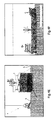
- FIG 1 is a longitudinal cross section of an underwater drilling device according to the invention.
- the underwater drilling device 1 is made up of a drilling device 2 which is provided within an upwardly closed-off space 3.
- the upwardly closed-off space 3 is formed by the internal space within a sea container.
- the dimensions of the sea container 3 are standardized in accordance with an ISO standard, the sea container 3 having a length of approximately 6 m and having a width and height of approximately 2.5 m.
- the sea container 3 has an internal space which is sufficiently large for placing a conventional drilling device 2, such as can also be used on land.
- the underwater drilling device 1 is advantageously constructed in a modular manner with the aid of the standardized sea container 3 and the conventional drilling device 2.
- the drilling device 2 is positioned in its entirety within the sea container 3. Merely lines for operating, supplying and discharging flushing liquids and hardening substances to and from the drilling device extend to outside the sea container 3.
- the drilling device 2 is provided with a drilling unit having a drive unit 21 and an alignment unit 22.
- the drive unit 21 drives in rotation drill pipes which can be placed in the alignment unit 22.
- the drill pipes which are placed in the seabed have to be made up of a plurality of drill pipe parts having a length of approximately 2.5 m.
- the drill pipe can be placed in the seabed by adjusting the alignment unit 22 at an angle ⁇ with respect to the seabed.
- the alignment unit 22 can be set at the angle ⁇ with the aid of a hydraulic cylinder.
- the angle ⁇ can for example be set to an angle of at most 60° with respect to a lower edge 3a.
- the angle ⁇ is adjustable between at least 15° and at most 45°, but more preferably the angle ⁇ is adjustable between at least 15° and at most 35°.
- the underwater drilling device 1 is sunk down to the seabed, the lower edge 3a of the sea container 3 entering into contact with the seabed.
- the underside of the sea container 3 is at least partly open.
- a drill pipe can be passed through the open underside of the sea container 3.
- the drill pipe extends through the open underside of the sea container 3 and is, in the method according to the invention, placed in the seabed with the aid of the drive unit 21.
- the position on the seabed where the drill pipe enters into contact with the seabed determines the starting point 4 of the drilling.
- the environment around the starting point is kept in an environment of a gaseous medium. This allows clear observation of the starting point.
- the starting point 4 on the seabed corresponds substantially to the point of intersection of the drill pipe with the plane formed by the open underside 3a.
- the underwater drilling device 1 shown in Fig. 1 is suitable for carrying out the method according to the invention.
- the internal space within the sea container 3 is provided with a gaseous medium, for example atmospheric air, while the drill pipe is driven into the seabed.
- the presence of the gaseous medium around the starting point 4 allows the drilling process to be monitored closely with the aid of observation means.
- the observation means (not shown here), such as cameras, are preferably attached within the cavity in the sea container 3.
- Figure 2 is a cross section of the underwater drilling device 1 from Figure 1 , the drilling device 2 further being provided with a repository 23.
- Drill pipe parts are stored in the repository 23.
- the drill pipe parts can be supplied with the aid of a gripper 231 to a coupling unit 232 which brings the drill pipe part into position within the drilling unit and provides a coupling to a previously introduced drill pipe part.
- the repository 23 is fully automated, so that no operator is necessary for the supply and coupling of drill pipe parts.
- the drilling device according to the invention can fully autonomously drive underwater a drill pipe into the seabed.
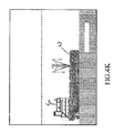
- Figure 3a is a side view of a particular embodiment of the method according to the invention.
- the ultimate aim of the method is to turn a capsized ship over about the longitudinal axis.
- anchorings 110, 120 are attached to both sides of the capsized ship 100.
- the anchoring 110 has a tensile anchor 111 which, in the method according to the invention as defined in claim 1, is attached in the seabed at an angle.
- use is made of an underwater drilling device as shown in Figures 1 and 2 .
- the fact that the tensile anchor 111 is attached in the seabed at an angle makes a positive contribution to the maximum permissible loading of the anchoring 110.
- At least one tensile body 101 is clamped between the capsized ship 100 and the anchoring 110.
- the tensile body 101 is in the first place above the seabed.
- the capsized ship 110 is turned over, the at least one tensile body 101 will rise up from the seabed and move more into line with the tensile anchor 111.
- An auxiliary vessel 130 is located on the other side of the capsized ship.
- the auxiliary vessel 130 is connected to the capsized ship 100 with the aid of at least one tensile body 103. Furthermore, the auxiliary vessel 130 is connected to the anchoring 120 with the aid of at least one tensile body 102.
- a device allowing clamping of the at least one tensile body 102 or 103 is positioned on board the vessel 130. The clamping produces a tensile force acting on the tensile body 103 or 102, subjecting the capsized ship 100 to a rotating moment over the longitudinal direction. This allows the capsized ship 100 to be advantageously rotated about the longitudinal axis. Once the capsized ship 100 has been turned back over, the tensile bodies 101, 102, 103 are detached and removed.
- Figure 3b is a plan view of an embodiment of the method for turning over the capsized ship 100.
- Tensile bodies 101, 102, 103 are attached to both sides of the capsized ship 100.
- Each tensile body is loaded as a result of the clamping with a load of approximately 3,000 - 5,000 kN.
- the ends of the tensile bodies are fastened to a plurality of anchorings in order proportionally to distribute the loads over the anchorings.
- Figure 4 shows schematically eleven steps of the method according to the invention which are denoted by Roman numerals I - XI, an auxiliary connecting element being attached to an end point on the seabed, from a starting point through the seabed, as a result of the underwater controlled drilling and a cutting element subsequently being passed through with the aid of the auxiliary connecting element.
- step I an underwater drilling device, as shown previously in Figure 1 , is launched from a vessel 41 with the aid of a hoisting crane and sunk down to the bed of the sea.
- the underwater drilling device 1 is positioned next to a sunken wreck 42 located on the seabed.
- the ultimate aim of the embodiment of the method as shown in the successive steps in Figure 4 is to cut the sunken wreck into pieces.
- step II shows the underwater device positioned on the seabed, the drilling device being positioned within an upwardly closed-off space.
- step II the drilling-at-an-angle of a drill pipe into the seabed has commenced.
- the drill pipe is made up of various drill pipe parts which are introduced into the seabed at an angle from a starting point 4 from the underwater drilling device.
- step III shows schematically how a curved drill passage is drilled with the aid of a controlled drill head.
- the controlled drilling provides a drill passage which extends from the starting point 4 in the underwater drilling device 1 through the seabed below the wreck 42 and comes up again and reaches the end point 5.
- a diver is present at the end point 5 of the drill passage.
- First a drill head at the distal end of the drill pipe is removed and subsequently the reamer 6 is fastened to the end of the drill pipe.
- An auxiliary connecting element 7 is subsequently coupled to the reamer.
- step IV shows how the drill pipe is withdrawn through the drill passage.
- the reamer 6 with the auxiliary connecting element 7 is also withdrawn to the starting point 4 at the location of the underwater drilling device. During the withdrawal, the drill pipe is rotated and flushing liquid is supplied.
- step V shows, the auxiliary connecting element 7 is fully withdrawn through the drill passage up to the starting point 4, so that after the drilling the auxiliary connecting element extends from the starting point 4 up to the end point 5 on the seabed.
- the use of the method according to the invention places an auxiliary connecting element, such as a line or chain, below the wreck.
- This auxiliary connecting element can subsequently be used for passing a cutting member 8 through below the wreck, allowing the wreck to be sawn into pieces.
- a hoisting cable which can be used to raise the wreck from the seabed, is fed through below the wreck with the aid of the auxiliary connecting element 7.
- step VI shows that after repeatedly carrying out the above-described steps of the method according to the invention, it is possible to attach a plurality of auxiliary connecting elements extending over the wreck 42.
- the auxiliary connecting elements are thus distributed over the longitudinal direction of the wreck 42.
- Figure 4 VIII shows the wreck on the seabed, hoisting lines 9 and cutting members being attached distributed over the longitudinal direction.
- the use of the method according to the invention allows the hoisting and cutting lines to be attached with precision in the desired position.
- An important advantage of the method according to the invention is that the lines pass under the wreck in a defined manner. As a result of the fact that the lines are drawn through the drill passage formed, the position of the lines is determined in advance in a reliable manner.
- the cutting member 8 be attached in the correct position, so that the wreck, such as a sunken ship with rigidifying ribs, is sawn through at the right spot.
- step IX is a plan view of the preparation for sawing through the wreck 42.
- a vessel 43 is placed above the wreck, at the surface of the water, and held in position with the aid of at least three tensile bodies 104, but preferably 4 tensile bodies.
- the tensile bodies 104 are connected to the vessel and an anchoring on the bed of the sea.
- the vessel 43 at the surface of the water is equipped with a hoisting installation. The hoisting installation can be used for sawing through the wreck and hoisting up parts of the wreck that have been cut loose.
- step X is a view of the sawing-through of the wreck.
- the elongate cutting member 8 is fastened at both ends to the hoisting crane on the vessel 43.
- the wreck 42 is sawn through by pulling the cutting member 8 upward and moving it back and forth.
- step XI shows the wreck on the bed of the sea, a portion of the wreck 43 having been sawn off and subsequently being hoisted up and removed.
- an alternative embodiment of an underwater drilling device can also be used for attaching a drill pipe in the seabed.
- a drilling device which is set up above the surface of the water. The drill pipe can be brought to the starting point on the seabed with the aid of a guide part for the drill pipe before drilling in the seabed commences.
Landscapes
- Engineering & Computer Science (AREA)
- Geology (AREA)
- Life Sciences & Earth Sciences (AREA)
- Mining & Mineral Resources (AREA)
- Mechanical Engineering (AREA)
- Physics & Mathematics (AREA)
- Environmental & Geological Engineering (AREA)
- Fluid Mechanics (AREA)
- General Life Sciences & Earth Sciences (AREA)
- Geochemistry & Mineralogy (AREA)
- Combustion & Propulsion (AREA)
- Ocean & Marine Engineering (AREA)
- Chemical & Material Sciences (AREA)
- Earth Drilling (AREA)
Abstract
Description
- The present invention relates to a method for carrying out underwater drilling, which is performed in particular for attaching an underwater anchoring. According to the method, an underwater drilling device is launched. The underwater drilling device has a drilling unit which is at least partly positioned within a substantially upwardly closed-off space. After the launching, the underwater drilling device is sunk down to the seabed. The underwater drilling device is positioned on the seabed. Subsequently, according to the method, a drill pipe is drilled into the seabed from a starting point on the seabed with the aid of a drilling unit. During the drilling, the course of the drilling is observed.
- A method of this type is known from
US 2005/0109537 which discloses an underwater drilling device for carrying out a drilling process. The underwater drilling device is launched from a ship with the aid of a hoisting crane, the underwater drilling device being fully submerged underwater and sunk down to the bed of the sea. The known underwater drilling device is designed to form a bored well; this commences with the attachment of a foundation guide. The underwater drilling device is modular in its construction and has at its centre a well head module which is fastened to the foundation guide. The foundation guide serves to anchor the underwater drilling device in soft seabeds. The foundation guide can be held vertically or at any desired angle by way of remote-control support points which are provided on the outside of the underwater drilling device. The underwater drilling device also has storage compartments for drill pipe parts which can be coupled with the aid of a mast module to the drill pipe which is placed in the seabed, so as to allow long drill pipes to be placed in the seabed. The underwater drilling device is connected to the ship with the aid of lines, so that flushing liquids for the drilling can be returned to the ship. Photos are taken with the aid of remote-control underwater vessels and equipment, and acoustic measurements are taken in order to be able to check and if necessary to adjust the drilling process on the bed of the sea. - A drawback of the known method with the aid of the known underwater drilling device is that the monitoring is limited over the course of the drilling. During the drilling of a drill pipe in the bed of the sea, all kinds of base materials rise up and cloud the direct environment of the underwater drilling device. This obscures the drilling process almost entirely. In addition, the direct environment of the underwater drilling device is further disturbed by the currents which are present above the seabed and the eddies which the drilling entails. These factors impede observation during the drilling. As a result of the poor observation, adequate monitoring of the drilling process is hardly possible and the drilling process is susceptible to interference.
- The object of the present invention is at least partly to overcome at least one of the above-mentioned drawbacks, or else to provide a practicable alternative. In particular, the invention seeks to provide an underwater drilling device and a method for carrying out underwater drilling, rendering the drilling process less susceptible to interference.
- This object is achieved by the method according to the invention such as is defined in
claim 1. - The method for carrying out underwater drilling according to the invention is particularly suitable for attaching an underwater anchoring. The drill pipe used can for example be an anchoring pipe. The anchoring pipe is for example a helical anchor, a helix being provided at the distal end of the pipe-shaped anchor. In the method according to the invention, an underwater drilling device is launched and sunk down to the seabed. The underwater drilling device is positioned on the seabed, so that a drill pipe can be drilled into the seabed from a starting point in the seabed with the aid of a drilling unit of the underwater drilling device. During the drilling, the course is observed. The observation can for example be carried out by divers who are present or with the aid of underwater cameras.
- It is characteristic of the method according to the invention that during the drilling the starting point on the seabed is held substantially in an environment of a gaseous medium. As a result, the starting point on the seabed is substantially free from water. The observation which takes place during the drilling is focused on the starting point on the seabed. By observing the starting point, the position where the drill pipe enters the seabed, it is possible purposefully to perceive whether the drilling process is being impeded. The course of the drilling can be monitored with the aid of the observation data. For example, slanting withdrawal of the drill pipe, which is visible at the starting point, is an indication of a possibly occurring disturbance.
- As a result of the fact that the direct environment around the starting point on the seabed is kept substantially free from water, no or hardly any clouding of the direct environment around the starting point will occur, so that the view of the starting point on the seabed remains clear even during the drilling.
- Preferably, the environment of a gaseous medium is an air environment. Base materials which rise up during the drilling will not mix with the gaseous environment, so that the view of the starting point is not disturbed.
- During the drilling, as a result of the improved observation according to the invention, the operator has an improved overview of the drilling process. It is for example readily possible for the operator to perceive in the environment of a gaseous medium when a drill pipe is placed at a angle in the seabed or when the drill pipe experiences high resistance in the seabed. As a result of the improved targeted observation in the gaseous environment around the starting point, the operator can intervene more rapidly when the drilling process is not going well. This advantageously prevents disturbances.
- Preferably, the underwater drilling device is sunk by venting a compartment of the underwater drilling device. Preferably, the compartment used for this purpose is the substantially upwardly closed-off space. The underwater drilling device can be launched from a vessel for example with the aid of a hoisting crane, after which at least one compartment of the underwater drilling device fills up with water in a controlled manner. This allows the underwater drilling device to be sunk to the seabed in a reliable manner, wherein the underwater drilling device can disappear completely beneath the surface of the water.
- Preferably, the underwater device remains connected during the method according to the invention to a control station which is for example provided on a vessel or on the quay in order to operate the underwater drilling device. For this purpose, the underwater drilling device is connected to the control station by lines for, for example, discharging and supplying flushing liquids, hardening substances and hydraulic liquids.
- Preferably, after the sinking and positioning of the underwater drilling device on the seabed, an upwardly closed-off space around the drilling unit is substantially filled with a gaseous medium, before the drilling commences. This makes the environment around the starting point substantially free from water. The closed-off space around the drilling unit is preferably made free from water by supplying air from the control station. The water located in the closed-off space around the drilling unit will be displaced as a result of the supplying of air, thus producing an air environment around the drilling unit and at the location of the starting point before the drilling on the seabed.
- During the supplying of air to the closed-off space around the drilling unit, it is important that the underwater drilling device remain in position on the seabed. In order to stabilize the underwater drilling device on the seabed, the method according to the invention can include a step wherein the underwater drilling device is secured to the seabed. This can for example be brought about by providing the underwater drilling device with a ballast, by starting a drive on the outside of the underwater drilling device, which propels the underwater drilling device in the downward direction, or by operating securing members around the underwater drilling device.
- In a preferred embodiment of the method according to the invention, the drill pipe to be placed in the seabed comprises at least two drill pipe parts and the method also has a step wherein, from a starting point in the seabed, a first drill pipe part is drilled using a drilling unit of the underwater drilling device and a follow-up step wherein a following drill pipe part is coupled to the first drill pipe part. In particular when linking a following drill pipe part, it is important that there be a clear view onto the proximal end of the first drill pipe part placed in the seabed. Through the environment of a gaseous medium around the ends to be coupled of the drill pipe parts, the operator has a clear view when linking a following drill pipe part. As a result, the linking of the drill pipe parts to one another using the method according to the invention proceeds with less susceptibility to interference.
- Preferably, the method utilizes an underwater drilling device which is provided with a repository comprising drill pipe parts. Preferably, the repository is automated for supplying and coupling drill pipe parts. From the repository, the drill pipe parts can be fed for automated coupling to the first drill pipe part in the seabed. The advantage of automated coupling is that no divers are necessary for operating the underwater drilling device. Cameras are all that are required for observing the drilling process. As a result, the method according to the invention can advantageously be carried out even at a deep depth of at least 30 m.
- In a particular embodiment of the method according to the invention, an anchor block is coupled in a follow-up step to at least one of the anchoring pipes attached in the seabed. The anchor block can be coupled to an anchoring pipe in various ways. A simple embodiment of the method according to the invention utilizes anchoring pipes which are provided at the proximal end with a threaded end. The threaded end can for example be fastened by a diver to the proximal end of the anchoring pipe attached in the seabed. Rings, which subsequently serve as a support ring for the anchor block to be positioned, can be placed over the threaded ends. At least one hole is provided in the anchor block, so that the anchor block can be slid over the threaded end of the anchoring pipe until the anchor block rests on the support ring. The anchor block can subsequently be secured with the aid of a nut.
- In an alternative embodiment, the anchor block can also be coupled to an anchoring body in the seabed, which body is made of a hardened substance and has a strand. Once injected grout of the anchoring body has hardened, the strand is securely connected to the anchoring body and is flexible at the end; this contributes to simple fastening to the anchor block.
- Preferably, in the method according to the invention, after the coupling of the anchor block to an anchoring pipe, a cover is attached along the outer circumference of the anchor block, in such a way that a substantially closed-off chamber is formed below the anchor block. In particular when the seabed is uneven or extends obliquely, a flexible cover, such as for example a plate made of polyurethane or rubber, is suitable for accommodating nonuniformities on the seabed. After the attachment of the flexible cover, the closed-off chamber can be filled up by supplying a hardening substance. Once the substance has hardened, the anchor block is weighed down and the underwater anchoring can advantageously withstand greater loads. In an alternative embodiment of the method, the cover can already be attached along the outer circumference of the anchor block before the anchor block is launched.
- Finally, the method according to the invention, wherein an anchor block is linked, also has in a preferred embodiment a step wherein bulk cargo, for example stones, is attached against the outside of the cover of the anchor block. As a result, the anchoring advantageously has greater resistance to the influences of currents.
- The anchor block which is attached using the method according to the invention can advantageously be used for anchoring an SBM (single buoy mooring). Anchoring the SBM according to the invention provides a robust and reliable anchoring. In a particular embodiment, the anchor block to be fastened is configured as a PLEM (pipeline end manifold). Various oil or gas lines on the bed of the sea can be coupled to one another with the aid of the PLEM. Carrying out the method according to the invention advantageously allows the PLEM to be positioned with precision on the seabed.
- The invention also relates to an underwater drilling device with a drilling unit which is positioned at least partly within an upwardly substantially closed-off space. The drilling unit comprises an alignment unit for aligning drill pipes and a drive unit for driving the drill pipes into the seabed. Preferably, the drive unit provides a drive in rotation. The distal end of a drill pipe enters into contact with the seabed and is preferably provided with a drill head. The position of this point of contact defines the starting point on the seabed. The position on the seabed where the distal end of the drill pipe enters the seabed determines the starting point. The upwardly closed-off space of the underwater drilling device is provided at the location of this starting point and has downwardly an opening through which a drill pipe can be passed. Preferably, the underwater drilling device rests on the seabed with the underside of the upwardly closed-off space. Once the underwater drilling device has been positioned on the seabed, the starting point on the seabed coincides substantially with the point of intersection of a drill pipe, which is passed through the opening of the upwardly closed-off space, in the plane formed by the underside of the drilling device.
- It is characteristic of the underwater drilling device according to the invention that a gaseous medium can be held within the closed-off space, allowing the space to be kept substantially free from water. Preferably, the closed-off space is substantially completely filled with ambient air during the drilling process. It is also characteristic that observation means are provided for monitoring the drilling process. At least one observation means is focused on the starting point. An observation means can for example be a camera or a diver. The observation means are located within the closed-off space of the underwater drilling device.
- An advantage of the underwater drilling device according to the invention is that the susceptibility of the underwater drilling device to interference is significantly reduced. As a result of the fact that the environment in the closed-off space is substantially gaseous during the drilling and as a result of the presence of observation means, the drilling process can be closely observed. A clear overview of the drilling process is obtained as a result of the fact that the position on the seabed where the drill pipe enters the seabed is clearly observable. When a drill pipe is slanting or when specific base materials rise up from the seabed, this is an indication to the operator that the drilling process requires adjustment. The purposefully set-up observation means within the closed-off space provide the operator with optimally rapid feedback on the drilling process. This greatly reduces the susceptibility of the drilling process to interference.
- In a preferred embodiment of the underwater drilling device, an air supply is connected to the upwardly closed-off space in order to make and to keep the space free from water. The air supply can for example be an air supply line extending from the underwater drilling device up to a control station located for example above the surface of the water on the quay or a ship. In an alternative embodiment, the air supply can be integrated into the underwater drilling device. In this case, the integrated air supply comprises a pressure vat, a pump and a line for supplying air to the closed-off space.
- In a further preferred embodiment, the drilling unit is provided substantially entirely within the closed-off space. Merely operating lines extend to outside the closed-off space. The closed-off space encloses the drilling unit and is preferably formed by the internal space of a sea container, an opening being provided in the underside of the sea container for passing through a drill pipe. Preferably, the drilling device is configured as a conventional drilling device which can be used also on land for driving drill pipes, such as an anchoring pipe, into the ground. An advantage of the embodiment of the underwater drilling device with a conventional drilling device in a sea container is that the underwater drilling device is modular in its construction. The use of standard components allows costs to be saved in the production and the maintenance of the underwater drilling device.
- In one embodiment according to the invention, the underwater drilling device is further provided with at least one securing member. The securing member is configured for holding the underwater drilling device on the seabed. The securing member can in one embodiment be configured as a ship's anchor which, after the sinking of the underwater drilling device to the seabed, anchors the underwater drilling device to the seabed, but can also be configured as a ballast which is attached to the underwater drilling device after the sinking of the underwater drilling device, thus weighing down the underwater drilling device.
- Preferably, however, the securing member is configured as an adjusting foot. The adjusting foot is provided on the outside of the underwater device and comprises a drivable anchoring body. Once the underwater drilling device has been sunk, the underwater drilling device can be positioned with the aid of the adjusting foot. Subsequently, the adjusting foot can be used to secure the underwater drilling device to the seabed. This advantageously stabilizes the underwater drilling device on the seabed. The securing of the underwater drilling device is particularly advantageous when air is supplied to the underwater drilling device, so that the underwater drilling device acquires the tendency to rise up. Advantageously, the securing member prevents the underwater drilling device from rising. Furthermore, at least one securing member prevents the underwater drilling device from getting out of position under the influence of currents underwater.
- In a particular embodiment of the underwater drilling device, the underwater drilling device is provided on the outside with at least one drive. The underwater drilling device can be adjusted during the sinking with the aid of the drive. This can prevent the underwater drilling device from sinking at an angle and being wrongly positioned on the seabed.
- In a further preferred embodiment of the underwater drilling device according to the invention, a repository is provided for supplying and coupling drill pipe parts. Preferably, the drill pipes to be introduced are made up of a plurality of drill pipe parts. In one embodiment of the underwater drilling device, wherein the drilling unit is substantially entirely enclosed by the upwardly closed-off space, the drill pipes have to be handled within this closed-off space. Advantageously, relatively long anchorings can be attached when the drill pipes are made up of a plurality of drill pipe parts. An advantage of the presence of the repository which is integrated within the underwater drilling device is that no drill pipe parts have to be fed from outside the drilling device, for example from a control station above the surface of the water. Preferably, the repository is automated for supplying and coupling drill pipe parts. This means that an operator does not have to be present underwater for coupling drill pipe parts. An advantage of the underwater drilling device according to the invention, wherein observation means are provided within the closed-off space, is that the coupling process of the drill pipe parts is also clearly observable. As a result, timely adjustment is possible when the coupling or supplying of drill pipe parts is found not to be proceeding in the desired manner. This embodiment according to the invention not only allows the drilling to proceed in a manner less susceptible to interference, but rather the reliability during the linking and supplying of drill pipe parts is also increased.
- The invention also relates to an underwater anchoring such as is defined in claim 16 and can be obtained after the carrying-out of the method having the steps defined in claims 7 - 9. The underwater anchoring according to the invention comprises at least one anchoring pipe, an anchor block being fastened to the anchoring pipe and the anchor block being weighed down by a hardening substance which is injected into a closed-off chamber below the anchor block.
- An advantage of the underwater anchoring is that just these few components provide an extremely robust anchoring. In particular, the weighting of a hardened substance contributes to the maximum permissible loading of the underwater anchoring.
- In a preferred embodiment of the underwater anchoring, the anchor block comprises a flexible cover along the outer circumference. The flexible cover is for example a thin plastics material plate which is connected to the anchor block at a circumferential edge. The flexible cover helps to provide a closed-off space below the anchor block. Unevenness on the seabed as a result of pits which are present or an oblique course of the seabed can be at least partly compensated for by the flexible cover. This is advantageous, because this prevents the injected hardened substance, during the attachment of the weighting below the anchor block, from running therefrom.
- In a further preferred embodiment of the underwater anchoring, bulk cargo is provided against the outside of the flexible cover in order to improve the closing-off of the space below the anchor block and in order further to weigh down the underwater anchoring.
- The method described hereinbefore for carrying out underwater drilling for attaching an underwater anchoring and the described underwater drilling device according to the invention are particularly suitable for use in a method for turning over a capsized ship.
- The invention further relates to a method for turning over a capsized ship as defined in claim 19. The method according to the invention can be used to turn back over a capsized ship which may or may not have sunk down to the seabed. The capsized ship has to be turned over about the longitudinal axis. In the method according to the invention, in a first step, at least one first underwater anchoring is attached to one side of the longitudinal direction of the capsized ship and at least one second underwater anchoring is attached to the opposing side of the capsized ship. Preferably, the underwater anchorings are attached using the method as defined in
claim 1. The capsized ship is thus given underwater anchorings on both sides. Subsequently, on one side of the capsized ship, at least one tensile body is clamped between the first underwater anchoring and the capsized ship. Also on the other edge of the capsized ship, at least one tensile body is clamped between the capsized ship and an auxiliary vessel. The auxiliary vessel is a driving object, such as a ship or pontoon. Consequently, at least one tensile body is fastened on either side of the capsized ship. The point at which the at least one tensile body is fastened to the capsized ship between the auxiliary vessel and the capsized ship is at a higher position than the point at which a tensile body is fastened to the capsized ship on the opposing side between the first underwater anchoring and the capsized ship. In the method according to the invention, in a first step, at least one tensile body is also clamped between the auxiliary vessel and the second underwater anchoring. Finally, the capsized ship is turned over by exerting a tensile force on the at least one tensile body between the auxiliary vessel and the second underwater anchoring. The exerting of a tensile force on the at least one tensile body between the auxiliary vessel and the second underwater anchoring also places the tensile bodies between the auxiliary vessel and the capsized ship and between the capsized ship and the first underwater anchoring under tension. In one embodiment of the method according to the invention, a tensile force can be exerted on the at least one tensile body between the auxiliary vessel and the capsized ship and/or a tensile force can be exerted on the at least one tensile body between the second underwater anchoring and the auxiliary vessel in order ultimately to transmit the tensile forces to the capsized ship. As a result of the fact that the points at which the tensile bodies are fastened to both sides of the capsized ship are positioned at differing heights, a rotating moment occurs on the capsized ship, allowing it to turn back over. - The tensile bodies between the first underwater anchoring and the capsized ship advantageously prevent the capsized ship from sliding away. In an alternative embodiment, sliding-away of the capsized ship can also be prevented by placing an obstacle on the seabed against the side wall of the ship on the side where the auxiliary vessel is also positioned. The obstacle against the side wall of the ship can be anchored in the seabed using the method according to the invention as defined in claims 1 - 9.
- Preference is given to a tensile body which is loaded to 3,000 kN, coupled to an underwater anchoring which is attached by at least two anchoring pipes using the method as defined in
claim 1. Preference is given to a tensile body which is loaded to 5,000 kN, coupled to an underwater anchoring by at least three anchoring pipes. Advantageously, a robust and reliable device is in this way obtained in order to turn over the capsized ship. - Also, the method according to the invention as defined in claims 1 - 6 is particularly applicable for use in a method for attaching an auxiliary connecting element, such as a line or chain, to an end point on the seabed, from a starting point through the seabed. In a following aspect, the invention relates to a method for attaching underwater an auxiliary connecting element, such as a line or a chain, to an end point on the seabed, from a starting point through the seabed. The method according to the invention includes a number of steps. In a first step, an underwater drilling device is sunk to the seabed. Subsequently, the underwater drilling device is positioned on the seabed. The sunk and positioned underwater drilling device comprises a drilling unit which can be set up at a fixed or variably adjustable drilling angle with respect to the seabed. The positioning of the underwater drilling unit or the separate adjusting of an alignment unit of the drilling unit places the drilling unit at a specific drilling angle. In particular, the drilling angle of the drilling unit is between at least 10° and at most 60° with respect to the seabed. Preferably, the drilling angle is between at least 15° and at most 35°. Subsequently, a drill passage can be drilled at the drilling angle from the starting point on the seabed. This is carried out using a first drill pipe which is provided with a controllable drill head. Subsequently, the drill head is steered through the seabed to the end point on the seabed. The drilling process thus does not have to be rectilinear, but rather can enclose a specific curvature. If for example the end point is at the same level as the starting point, the drilling process will have to have a curvature in order to reach the end point from the starting point. Once the first drill pipe has reached the end point, the controllable drill head can be removed and a reamer with an elongate flexible auxiliary connecting element is coupled to the drill pipe. Subsequently, in the method according to the invention, the drill pipe is withdrawn through the drill passage, in such a way that the reamer and the auxiliary connecting element are also withdrawn to the starting point on the seabed.
- Preferably, during the withdrawal, the drilling pipe is rotated and a flushing liquid supplied through the drill pipe. This facilitates the withdrawal. As the end result of the method according to the invention, the auxiliary connecting element is positioned in the seabed through the drill passage. Both ends of the auxiliary connecting element protrude at the starting point and the end point. The auxiliary connecting element can for example be used to pull a chain with links and saw teeth or a line with cutting elements through the drill passage. Subsequently, the line or chain with saw teeth can be used to cut or saw into pieces an object, for example a wreck, which is located above the line or chain by pulling the line or chain upward and moving it back and forth.
- In order to drill a drill passage over a large distance, in the method according to the invention, each at least one following drill pipe part is preferably coupled to a preceding drill pipe part. Preferably, the drill pipe parts are fed from a repository of the underwater drilling device and coupled to the first drill pipe in an automated manner.
- Further preferred embodiments are defined in the remaining sub-claims. Incidentally, it should be noted that an underwater foundation ship is known from the abstract of Japanese patent application
JP-4231515 - A drawback of this foundation ship is that the foundation process is susceptible to interference, because there is no clear outlook onto the process. In addition, the length of the drill pipe to be placed in the seabed is restricted with the aid of the described foundation ship. The foundation ship makes no provision for the coupling-together of various drill pipe parts.
- The invention will be described in greater detail with reference to appended drawings which show a practical embodiment of the invention, but may not be viewed in a limiting sense, and in which:
-
Fig. 1 is a longitudinal cross section over the underwater drilling device according to the invention; -
Fig. 2 is a cross section of the underwater drilling device; -
Fig. 3a is a side view of an embodiment of the method according to the invention, wherein a capsized ship is turned over; -
Fig. 3b is a plan view of the method according toFigure 3a ; and -
Fig. 4 is a schematic representation of successive steps from the method according to the invention; wherein an auxiliary connecting element is steered through below a ship by drilling in a controlled manner. -
Figure 1 is a longitudinal cross section of an underwater drilling device according to the invention. Theunderwater drilling device 1 is made up of adrilling device 2 which is provided within an upwardly closed-offspace 3. In this case, the upwardly closed-offspace 3 is formed by the internal space within a sea container. The dimensions of thesea container 3 are standardized in accordance with an ISO standard, thesea container 3 having a length of approximately 6 m and having a width and height of approximately 2.5 m. Thesea container 3 has an internal space which is sufficiently large for placing aconventional drilling device 2, such as can also be used on land. Theunderwater drilling device 1 is advantageously constructed in a modular manner with the aid of thestandardized sea container 3 and theconventional drilling device 2. - The
drilling device 2 is positioned in its entirety within thesea container 3. Merely lines for operating, supplying and discharging flushing liquids and hardening substances to and from the drilling device extend to outside thesea container 3. Thedrilling device 2 is provided with a drilling unit having adrive unit 21 and analignment unit 22. Thedrive unit 21 drives in rotation drill pipes which can be placed in thealignment unit 22. The drill pipes which are placed in the seabed have to be made up of a plurality of drill pipe parts having a length of approximately 2.5 m. The drill pipe can be placed in the seabed by adjusting thealignment unit 22 at an angle α with respect to the seabed. Thealignment unit 22 can be set at the angle α with the aid of a hydraulic cylinder. The angle α can for example be set to an angle of at most 60° with respect to a lower edge 3a. Preferably the angle α is adjustable between at least 15° and at most 45°, but more preferably the angle α is adjustable between at least 15° and at most 35°. - In the method according to the invention, the
underwater drilling device 1 is sunk down to the seabed, the lower edge 3a of thesea container 3 entering into contact with the seabed. The underside of thesea container 3 is at least partly open. A drill pipe can be passed through the open underside of thesea container 3. The drill pipe extends through the open underside of thesea container 3 and is, in the method according to the invention, placed in the seabed with the aid of thedrive unit 21. The position on the seabed where the drill pipe enters into contact with the seabed determines thestarting point 4 of the drilling. In the method according to the invention, when the drill pipe is driven into the seabed, the environment around the starting point is kept in an environment of a gaseous medium. This allows clear observation of the starting point. Thestarting point 4 on the seabed corresponds substantially to the point of intersection of the drill pipe with the plane formed by the open underside 3a. - The
underwater drilling device 1 shown inFig. 1 is suitable for carrying out the method according to the invention. For this purpose, the internal space within thesea container 3 is provided with a gaseous medium, for example atmospheric air, while the drill pipe is driven into the seabed. The presence of the gaseous medium around thestarting point 4 allows the drilling process to be monitored closely with the aid of observation means. The observation means (not shown here), such as cameras, are preferably attached within the cavity in thesea container 3. -
Figure 2 is a cross section of theunderwater drilling device 1 fromFigure 1 , thedrilling device 2 further being provided with arepository 23. Drill pipe parts are stored in therepository 23. The drill pipe parts can be supplied with the aid of agripper 231 to acoupling unit 232 which brings the drill pipe part into position within the drilling unit and provides a coupling to a previously introduced drill pipe part. Therepository 23 is fully automated, so that no operator is necessary for the supply and coupling of drill pipe parts. Advantageously, the drilling device according to the invention can fully autonomously drive underwater a drill pipe into the seabed. -
Figure 3a is a side view of a particular embodiment of the method according to the invention. The ultimate aim of the method is to turn a capsized ship over about the longitudinal axis. For this purpose, in a first step of the method according to the invention,anchorings ship 100. The anchoring 110 has atensile anchor 111 which, in the method according to the invention as defined inclaim 1, is attached in the seabed at an angle. In order to attach the anchoring 110, use is made of an underwater drilling device as shown inFigures 1 and2 . The fact that thetensile anchor 111 is attached in the seabed at an angle makes a positive contribution to the maximum permissible loading of the anchoring 110. In the method according to the invention, at least onetensile body 101 is clamped between the capsizedship 100 and the anchoring 110. In this case, thetensile body 101 is in the first place above the seabed. When the capsizedship 110 is turned over, the at least onetensile body 101 will rise up from the seabed and move more into line with thetensile anchor 111. - An
auxiliary vessel 130 is located on the other side of the capsized ship. Theauxiliary vessel 130 is connected to the capsizedship 100 with the aid of at least onetensile body 103. Furthermore, theauxiliary vessel 130 is connected to the anchoring 120 with the aid of at least onetensile body 102. A device allowing clamping of the at least onetensile body vessel 130. The clamping produces a tensile force acting on thetensile body ship 100 to a rotating moment over the longitudinal direction. This allows the capsizedship 100 to be advantageously rotated about the longitudinal axis. Once the capsizedship 100 has been turned back over, thetensile bodies -
Figure 3b is a plan view of an embodiment of the method for turning over the capsizedship 100.Tensile bodies ship 100. Each tensile body is loaded as a result of the clamping with a load of approximately 3,000 - 5,000 kN. Preferably, the ends of the tensile bodies are fastened to a plurality of anchorings in order proportionally to distribute the loads over the anchorings. -
Figure 4 shows schematically eleven steps of the method according to the invention which are denoted by Roman numerals I - XI, an auxiliary connecting element being attached to an end point on the seabed, from a starting point through the seabed, as a result of the underwater controlled drilling and a cutting element subsequently being passed through with the aid of the auxiliary connecting element. - In the first step I, an underwater drilling device, as shown previously in
Figure 1 , is launched from avessel 41 with the aid of a hoisting crane and sunk down to the bed of the sea. Theunderwater drilling device 1 is positioned next to asunken wreck 42 located on the seabed. The ultimate aim of the embodiment of the method as shown in the successive steps inFigure 4 is to cut the sunken wreck into pieces.Figure 4 , step II shows the underwater device positioned on the seabed, the drilling device being positioned within an upwardly closed-off space. In step II the drilling-at-an-angle of a drill pipe into the seabed has commenced. The drill pipe is made up of various drill pipe parts which are introduced into the seabed at an angle from astarting point 4 from the underwater drilling device. -
Figure 4 , step III shows schematically how a curved drill passage is drilled with the aid of a controlled drill head. The controlled drilling provides a drill passage which extends from thestarting point 4 in theunderwater drilling device 1 through the seabed below thewreck 42 and comes up again and reaches theend point 5. At theend point 5 of the drill passage, a diver is present for attaching a reamer 6. First a drill head at the distal end of the drill pipe is removed and subsequently the reamer 6 is fastened to the end of the drill pipe. An auxiliary connectingelement 7 is subsequently coupled to the reamer. -
Figure 4 , step IV shows how the drill pipe is withdrawn through the drill passage. The reamer 6 with the auxiliary connectingelement 7 is also withdrawn to thestarting point 4 at the location of the underwater drilling device. During the withdrawal, the drill pipe is rotated and flushing liquid is supplied. - As
Figure 4 , step V shows, the auxiliary connectingelement 7 is fully withdrawn through the drill passage up to thestarting point 4, so that after the drilling the auxiliary connecting element extends from thestarting point 4 up to theend point 5 on the seabed. The use of the method according to the invention places an auxiliary connecting element, such as a line or chain, below the wreck. This auxiliary connecting element can subsequently be used for passing a cuttingmember 8 through below the wreck, allowing the wreck to be sawn into pieces. In an alternative embodiment of the method, a hoisting cable, which can be used to raise the wreck from the seabed, is fed through below the wreck with the aid of the auxiliary connectingelement 7. -
Figure 4 , step VI shows that after repeatedly carrying out the above-described steps of the method according to the invention, it is possible to attach a plurality of auxiliary connecting elements extending over thewreck 42. The auxiliary connecting elements are thus distributed over the longitudinal direction of thewreck 42. - The following schematic views, denoted by reference numerals VII - XII, subsequently represent how the wreck on the seabed can be sawn through with the aid of the cutting
member 8. - In
Figure 4 VII a chain with cutting elements is passed below the wreck with the aid of the auxiliary connecting element. -
Figure 4 VIII shows the wreck on the seabed, hoistinglines 9 and cutting members being attached distributed over the longitudinal direction. The use of the method according to the invention allows the hoisting and cutting lines to be attached with precision in the desired position. An important advantage of the method according to the invention is that the lines pass under the wreck in a defined manner. As a result of the fact that the lines are drawn through the drill passage formed, the position of the lines is determined in advance in a reliable manner. In particular for sawing through a wreck, it is important that the cuttingmember 8 be attached in the correct position, so that the wreck, such as a sunken ship with rigidifying ribs, is sawn through at the right spot. When sawing through a ship, it is for example desirable to saw through the ship between the rigidifying ribs. Also if for example liquid reservoirs are on board the wreck, it is desirable to saw through the wreck at positions defined with precision in advance. The use of the method according to the invention, one of the steps of which is to form a drill passage by drilling underwater with a controllable drill head, advantageously makes this possible. -
Figure 4 , step IX is a plan view of the preparation for sawing through thewreck 42. Avessel 43 is placed above the wreck, at the surface of the water, and held in position with the aid of at least threetensile bodies 104, but preferably 4 tensile bodies. Thetensile bodies 104 are connected to the vessel and an anchoring on the bed of the sea. Thevessel 43 at the surface of the water is equipped with a hoisting installation. The hoisting installation can be used for sawing through the wreck and hoisting up parts of the wreck that have been cut loose. -
Figure 4 , step X is a view of the sawing-through of the wreck. Theelongate cutting member 8 is fastened at both ends to the hoisting crane on thevessel 43. Thewreck 42 is sawn through by pulling the cuttingmember 8 upward and moving it back and forth. -
Figure 4 , step XI shows the wreck on the bed of the sea, a portion of thewreck 43 having been sawn off and subsequently being hoisted up and removed. The use of the method according to the invention advantageously provides an efficient and purposeful method for salvaging a wreck. - In addition to the embodiments shown in the figures, a large number of variations are possible. In a variation on the embodiment shown of the methods for turning over or salvaging a wreck, an alternative embodiment of an underwater drilling device can also be used for attaching a drill pipe in the seabed. In a variant, for example in a work area of limited depth or if a quay is nearby, use can be made of a drilling device which is set up above the surface of the water. The drill pipe can be brought to the starting point on the seabed with the aid of a guide part for the drill pipe before drilling in the seabed commences.
- Aspects of the invention can be described by one or more of the following clauses:
- 1. Method for carrying out underwater drilling, in particular for attaching an underwater anchoring, including the steps:
- launching an underwater drilling device with a drilling unit which is at least partly positioned within a substantially upwardly closed-off space;
- sinking the underwater drilling device down to the seabed;
- positioning the underwater drilling device on the seabed;
- drilling a drill pipe from a starting point in the seabed with the aid of a drilling unit of the underwater drilling device;
- observing the course of the drilling;
- 2. Method according to
clause 1, wherein the underwater drilling device is sunk by venting a compartment of the underwater drilling device. - 3. Method according to
clause - 4. Method according to one of the preceding clauses, wherein the drill pipe comprises at least two drill pipe parts and the method further includes the step of:
- drilling a first drill pipe part from a starting point in the seabed using a drilling unit of the underwater drilling device;
- linking a following drill pipe part to the first drill pipe part.
- 5. Method according to
clause 4, wherein the drilling unit comprises a repository from which drill pipe parts are fed for automated coupling to the first drill pipe part in the seabed. - 6. Method according to one of the preceding clauses, wherein the drill pipe is drilled at an angle with respect to the seabed.
- 7. Method according to one of the preceding clauses, wherein an anchor block is coupled to at least one anchoring pipe attached in the seabed.
- 8. Method according to one of the preceding clauses, wherein the method further includes the steps of:
- attaching a cover along the outer circumference of the anchor block, in such a way that a closed-off chamber is formed below the anchor block;
- filling up the closed-off chamber with a hardening substance.
- 9. Method according to one of the preceding clauses, wherein the method further includes the step:
- attaching bulk cargo against the outside of the cover.
- 10. Underwater drilling device with a drilling unit which is at least partly positioned within a substantially upwardly closed-off space, the drilling unit:
- comprising an alignment unit for aligning drill pipes; and
- comprising a drive unit for driving the drill pipes from a starting point in the seabed, the closed-off space being provided at the location of the starting point, characterized in that a gaseous medium environment is to be maintained in the upwardly closed-off space and in that observation means are also provided within the closed-off space for observing the starting point for monitoring the course of the drilling.
- 11. Underwater drilling device according to clause 10, wherein an air supply is connected to the closed-off space in order to keep the space free from water.
- 12. Underwater drilling device according to clause 10 or 11, wherein the closed-off space around the drilling unit is formed by the internal space within a sea container.
- 13. Underwater drilling device according to one of clauses 10 - 12, wherein a securing member is provided for holding the underwater drilling device on the seabed.
- 14. Underwater drilling device according to one of clauses 10 - 13, wherein at least one drive is provided on the outside for positioning the underwater drilling device on the seabed.
- 15. Underwater drilling device according to one of clauses 10 - 14, wherein a repository is also provided for supplying and coupling drill pipe parts.
- 16. Underwater anchoring comprising at least one anchoring pipe, wherein an anchor block is fastened to the anchoring pipe and wherein the anchor block comprises weighting of a hardened substance which is injected into a closed-off chamber below the anchor block.
- 17. Underwater anchoring according to clause 16, wherein the anchor block comprises a flexible cover along the outer circumference.
- 18. Use of the method according to clauses 1 - 9 for turning over a capsized ship.
- 19. Method for turning over a capsized ship including the following steps:
- attaching at least one first underwater anchoring to one side of the longitudinal direction of the capsized ship and at least one second underwater anchoring to the opposing side of the capsized ship;
- clamping to one side of the capsized ship at least one tensile body between the first underwater anchoring and the capsized ship;
- clamping to the opposing side of the capsized ship at least one tensile body between an auxiliary vessel (driving object) and the capsized ship, wherein the point at which the tensile body is fastened to the capsized ship between the auxiliary vessel and the capsized ship is at a higher position than the point at which the tensile body is fastened to the capsized ship on the opposing side between the first underwater anchoring and the capsized ship;
- clamping at least one tensile body between the auxiliary vessel and the second underwater anchoring on the opposing side of the capsized ship;
- exerting a tensile force on the at least one tensile body between the auxiliary vessel and the second underwater anchoring.
- 20. Method according to clause 19, wherein a tensile body which is loaded to 3,000 kN is coupled to an underwater anchoring by at least two anchoring pipes, a tensile body which is loaded to 5,000 kN being coupled to an underwater anchoring by at least three anchoring pipes.
- 21. Use of the method according to one of clauses 1 - 9 for attaching an auxiliary connecting element, such as a line or chain, to an end point on the seabed, from a starting point through the seabed.
- 22. Method for attaching underwater an auxiliary connecting element, such as a line or a chain, to an end point on the seabed, from a starting point through the seabed, including the following steps:
- sinking an underwater drilling device to the seabed;
- positioning the underwater drilling device on the seabed;
- placing a drilling unit of the underwater drilling device at a drilling angle;
- drilling a drill passage at the drilling angle from the starting point using a first drill pipe which is provided with a controllable drill head;
- steering the drill head through the seabed to the end point on the seabed;
- linking at the end point a reamer with an elongate flexible auxiliary connecting element to the drill pipe;
- withdrawing the reamer with the auxiliary connecting element to the starting point on the seabed.
- 23. Method according to
clause 22, wherein the drilling angle of the drilling unit is between at least 10° and at most 60° with respect to the seabed. - 24. Method according to
clause - 25. Method according to one of the clauses 22 - 24, wherein flushing liquid is supplied during the withdrawal of the reamer through the drill passage.
- 26. Method according to one of the clauses 22 - 25, wherein in a following step an elongate cutting member is passed through the drill passage with the aid of the auxiliary connecting element.
Claims (15)
- Method for carrying out underwater drilling for attaching an underwater anchoring, comprising the steps:- launching an underwater drilling device with a drilling unit which is at least partly positioned within a substantially upwardly closed-off space;- sinking the underwater drilling device down to the seabed;- positioning the underwater drilling device on the seabed;- drilling a drill pipe from a starting point in the seabed with the aid of a drilling unit of the underwater drilling device;- observing the course of the drilling;characterized in that during the drilling the starting point on the seabed is held substantially in an environment of a gaseous medium, the course of the drilling being monitored by observing the starting point.
- Method according to claim 1, wherein the underwater drilling device is sunk by venting a compartment of the underwater drilling device.
- Method according to claim 1 or 2, wherein a closed-off space around the drilling unit is made substantially free from water after the sinking of the underwater drilling device before drilling is commenced.
- Method according to one of the preceding claims, wherein the drill pipe comprises at least two drill pipe parts and the method further includes the step of:- drilling a first drill pipe part from a starting point in the seabed using a drilling unit of the underwater drilling device;- linking a following drill pipe part to the first drill pipe part.
- Method according to claim 4, wherein the drilling unit comprises a repository from which drill pipe parts are fed for automated coupling to the first drill pipe part in the seabed.
- Method according to one of the preceding claims, wherein the method further includes the steps of:- coupling an anchor block to at least one anchoring pipe attached in the base;- attaching a cover along the outer circumference of the anchor block, in such a way that a closed-off chamber is formed below the anchor block;- filling up the closed-off chamber with a hardening substance.
- Underwater drilling device with a drilling unit which is at least partly positioned within a substantially upwardly closed-off space, the drilling unit:- comprising an alignment unit for aligning drill pipes; and- comprising a drive unit for driving the drill pipes from a starting point in the seabed, the closed-off space being provided at the location of the starting point, characterized in that a gaseous medium environment is to be maintained in the upwardly closed-off space and in that observation means are also provided within the closed-off space for observing the starting point for monitoring the course of the drilling.
- Underwater drilling device according to claim 7, wherein the closed-off space around the drilling unit is formed by the internal space of a sea container.
- Underwater anchoring comprising at least one anchoring pipe, wherein an anchor block is fastened to the anchoring pipe and wherein the anchor block comprises weighting of a hardened substance which is injected into a closed-off chamber below the anchor block.
- Use of the method according to claims 1 - 6 for turning over a capsized ship including the following steps:- attaching at least one first underwater anchoring to one side of the longitudinal direction of the capsized ship and at least one second underwater anchoring to the opposing side of the capsized ship;- clamping to one side of the capsized ship at least one tensile body between the first underwater anchoring and the capsized ship;- clamping to the opposing side of the capsized ship at least one tensile body between a driving object and the capsized ship, wherein the point at which the tensile body is fastened to the capsized ship between the auxiliary vessel and the capsized ship is at a higher position than the point at which the tensile body is fastened to the capsized ship on the opposing side between the first underwater anchoring and the capsized ship;- clamping at least one tensile body between the auxiliary vessel and the second underwater anchoring on the opposing side of the capsized ship;- exerting a tensile force on the at least one tensile body between the auxiliary vessel and the second underwater anchoring.
- Method for turning over a capsized ship including the following steps:- attaching at least one first underwater anchoring to one side of the longitudinal direction of the capsized ship and at least one second underwater anchoring to the opposing side of the capsized ship;- clamping to one side of the capsized ship at least one tensile body between the first underwater anchoring and the capsized ship;- clamping to the opposing side of the capsized ship at least one tensile body between an auxiliary vessel (driving object) and the capsized ship, wherein the point at which the tensile body is fastened to the capsized ship between the auxiliary vessel and the capsized ship is at a higher position than the point at which the tensile body is fastened to the capsized ship on the opposing side between the first underwater anchoring and the capsized ship;- clamping at least one tensile body between the auxiliary vessel and the second underwater anchoring on the opposing side of the capsized ship;- exerting a tensile force on the at least one tensile body between the auxiliary vessel and the second underwater anchoring.
- Use of the method according to one of claims 1 - 6 for attaching underwater an auxiliary connecting element, such as a line or chain, to an end point on the seabed, from a starting point through the seabed, including the following steps:- sinking an underwater drilling device to the seabed;- positioning the underwater drilling device on the seabed;- placing a drilling unit of the underwater drilling device at a drilling angle;- drilling a drill passage at the drilling angle from the starting point using a first drill pipe which is provided with a controllable drill head;- steering the drill head through the seabed to the end point on the seabed;- linking at the end point a reamer with an elongate flexible auxiliary connecting element to the drill pipe;- withdrawing the reamer with the auxiliary connecting element to the starting point on the seabed.
- Method for attaching underwater an auxiliary connecting element, such as a line or a chain, to an end point on the seabed, from a starting point through the seabed, including the following steps:- sinking an underwater drilling device to the seabed;- positioning the underwater drilling device on the seabed;- placing a drilling unit of the underwater drilling device at a drilling angle;- drilling a drill passage at the drilling angle from the starting point using a first drill pipe which is provided with a controllable drill head;- steering the drill head through the seabed to the end point on the seabed;- linking at the end point a reamer with an elongate flexible auxiliary connecting element to the drill pipe;- withdrawing the reamer with the auxiliary connecting element to the starting point on the seabed.
- Method according to claim 13, wherein flushing liquid is supplied during the withdrawal of the reamer through the drill passage.
- Method according to claim 13 or 14, wherein in a following step an elongate cutting member is passed through the drill passage with the aid of the auxiliary connecting element.
Applications Claiming Priority (1)
| Application Number | Priority Date | Filing Date | Title |
|---|---|---|---|
| NL1034488A NL1034488C2 (en) | 2007-10-08 | 2007-10-08 | Underwater drilling device and method for performing an underwater drilling, in particular for applying an underwater anchor. |
Publications (3)
| Publication Number | Publication Date |
|---|---|
| EP2063067A1 true EP2063067A1 (en) | 2009-05-27 |
| EP2063067C0 EP2063067C0 (en) | 2023-07-26 |
| EP2063067B1 EP2063067B1 (en) | 2023-07-26 |
Family
ID=39335218
Family Applications (1)
| Application Number | Title | Priority Date | Filing Date |
|---|---|---|---|
| EP08166074.8A Active EP2063067B1 (en) | 2007-10-08 | 2008-10-08 | Underwater drilling device and method for carrying out underwater drilling, in particular for attaching an underwater anchoring |
Country Status (3)
| Country | Link |
|---|---|
| EP (1) | EP2063067B1 (en) |
| ES (1) | ES2965732T3 (en) |
| NL (1) | NL1034488C2 (en) |
Cited By (4)
| Publication number | Priority date | Publication date | Assignee | Title |
|---|---|---|---|---|
| EP2860341A1 (en) * | 2013-10-10 | 2015-04-15 | Soil Machine Dynamics Limited | Subsea support apparatus for supporting drive means, and driving apparatus incorporating such support apparatus |
| GB2533772A (en) * | 2014-12-23 | 2016-07-06 | Marine Current Turbines Ltd | Mooring anchor |
| CN112643084A (en) * | 2021-01-04 | 2021-04-13 | 交通运输部上海打捞局 | Underwater automatic tapping system for fishing |
| CN118407734A (en) * | 2024-07-03 | 2024-07-30 | 青岛恒海盛海洋科技有限公司 | Underwater base plate for ocean exploration |
Citations (13)
| Publication number | Priority date | Publication date | Assignee | Title |
|---|---|---|---|---|
| GB160865A (en) * | 1919-10-06 | 1921-04-07 | James Forgie | Improvements in and relating to submarine exploration |
| US2937006A (en) * | 1957-05-17 | 1960-05-17 | Sun Oil Co | Underwater drilling rig |
| US3602320A (en) * | 1968-10-16 | 1971-08-31 | Amoco Prod Co | Deep sea pile setting and coring vessel |
| DE2154231A1 (en) * | 1971-10-30 | 1973-05-03 | Erno Raumfahrttechnik Gmbh | DRILL ANCHOR ARRANGEMENT |
| US3934660A (en) * | 1974-07-02 | 1976-01-27 | Nelson Daniel E | Flexpower deep well drill |
| DE2638121A1 (en) * | 1976-08-25 | 1978-03-09 | Robert Teller | Reinforced concrete hemisphere as subsea drilling platform - can be lowered complete onto sea bed with ballast and buoyancy tanks |
| US4255068A (en) * | 1978-07-04 | 1981-03-10 | Techniques Industrielles Et Minieres | Method and a device for undersea drilling |
| US20030106714A1 (en) * | 2001-12-12 | 2003-06-12 | Smith Michael Lee | Use of coiled tubing unit systems in sub sea operations |
| WO2003053773A1 (en) * | 2001-12-20 | 2003-07-03 | Stolt Offshore Limited | Anchor for vehicle, vehicle and anchor in combination, and method of using the anchor |
| US20050109537A1 (en) | 2002-04-30 | 2005-05-26 | Ayling Laurence J. | Drilling rig |
| WO2006112821A1 (en) * | 2005-04-15 | 2006-10-26 | Victor Eli Velazquez | Anchoring systems and methods for anchoring an object |
| EP1914379A1 (en) * | 2006-10-19 | 2008-04-23 | Adel Sheshtawy | Underwater seafloor drilling rig |
| JP4231515B2 (en) | 2006-07-11 | 2009-03-04 | 東芝テリー株式会社 | Self-propelled in-pipe inspection camera system |
-
2007
- 2007-10-08 NL NL1034488A patent/NL1034488C2/en active Search and Examination
-
2008
- 2008-10-08 EP EP08166074.8A patent/EP2063067B1/en active Active
- 2008-10-08 ES ES08166074T patent/ES2965732T3/en active Active
Patent Citations (13)
| Publication number | Priority date | Publication date | Assignee | Title |
|---|---|---|---|---|
| GB160865A (en) * | 1919-10-06 | 1921-04-07 | James Forgie | Improvements in and relating to submarine exploration |
| US2937006A (en) * | 1957-05-17 | 1960-05-17 | Sun Oil Co | Underwater drilling rig |
| US3602320A (en) * | 1968-10-16 | 1971-08-31 | Amoco Prod Co | Deep sea pile setting and coring vessel |
| DE2154231A1 (en) * | 1971-10-30 | 1973-05-03 | Erno Raumfahrttechnik Gmbh | DRILL ANCHOR ARRANGEMENT |
| US3934660A (en) * | 1974-07-02 | 1976-01-27 | Nelson Daniel E | Flexpower deep well drill |
| DE2638121A1 (en) * | 1976-08-25 | 1978-03-09 | Robert Teller | Reinforced concrete hemisphere as subsea drilling platform - can be lowered complete onto sea bed with ballast and buoyancy tanks |
| US4255068A (en) * | 1978-07-04 | 1981-03-10 | Techniques Industrielles Et Minieres | Method and a device for undersea drilling |
| US20030106714A1 (en) * | 2001-12-12 | 2003-06-12 | Smith Michael Lee | Use of coiled tubing unit systems in sub sea operations |
| WO2003053773A1 (en) * | 2001-12-20 | 2003-07-03 | Stolt Offshore Limited | Anchor for vehicle, vehicle and anchor in combination, and method of using the anchor |
| US20050109537A1 (en) | 2002-04-30 | 2005-05-26 | Ayling Laurence J. | Drilling rig |
| WO2006112821A1 (en) * | 2005-04-15 | 2006-10-26 | Victor Eli Velazquez | Anchoring systems and methods for anchoring an object |
| JP4231515B2 (en) | 2006-07-11 | 2009-03-04 | 東芝テリー株式会社 | Self-propelled in-pipe inspection camera system |
| EP1914379A1 (en) * | 2006-10-19 | 2008-04-23 | Adel Sheshtawy | Underwater seafloor drilling rig |
Cited By (6)
| Publication number | Priority date | Publication date | Assignee | Title |
|---|---|---|---|---|
| EP2860341A1 (en) * | 2013-10-10 | 2015-04-15 | Soil Machine Dynamics Limited | Subsea support apparatus for supporting drive means, and driving apparatus incorporating such support apparatus |
| WO2015052075A1 (en) * | 2013-10-10 | 2015-04-16 | Soil Machine Dynamics Limited | Subsea support apparatus for supporting drive means, and driving apparatus incorporating such support apparatus |
| CN105593452A (en) * | 2013-10-10 | 2016-05-18 | 索尔机械动力有限公司 | Subsea support apparatus for supporting drive means, and driving apparatus incorporating such support apparatus |
| GB2533772A (en) * | 2014-12-23 | 2016-07-06 | Marine Current Turbines Ltd | Mooring anchor |
| CN112643084A (en) * | 2021-01-04 | 2021-04-13 | 交通运输部上海打捞局 | Underwater automatic tapping system for fishing |
| CN118407734A (en) * | 2024-07-03 | 2024-07-30 | 青岛恒海盛海洋科技有限公司 | Underwater base plate for ocean exploration |
Also Published As
| Publication number | Publication date |
|---|---|
| NL1034488C2 (en) | 2009-04-09 |
| ES2965732T3 (en) | 2024-04-16 |
| EP2063067C0 (en) | 2023-07-26 |
| EP2063067B1 (en) | 2023-07-26 |
Similar Documents
| Publication | Publication Date | Title |
|---|---|---|
| US6009825A (en) | Recoverable system for mooring mobile offshore drilling units | |
| US4575282A (en) | System for driving open end pipe piles on the ocean floor using pneumatic evacuation and existing hydrostatic pressure | |
| US6503023B2 (en) | Temporary floatation stabilization device and method | |
| US3754403A (en) | Offshore marine structure embodying anchor pile means | |
| US10207773B2 (en) | Corrosion-and-chafing-resistant, buoy system and method | |
| US3891037A (en) | Remotely operated seafloor coring and drilling method and system | |
| CN103228530A (en) | Floating body structure operation system, floating body structure, workboat and operation method of floating body structure | |
| KR101761587B1 (en) | Marine structure installation vessel and installing method of marine structure | |
| US8784011B2 (en) | Marine-equipment installation method and apparatus | |
| NO136650B (en) | ||
| WO2010093259A2 (en) | Offshore wind turbine | |
| EP1234978B1 (en) | Off-shore wind turbine | |
| EP2591175A1 (en) | Surface-breaking re-usable submergeable template for installing one or more submerged columns/piles | |
| EP2216447A1 (en) | Floating marine structure with suction piles and platform resting on a barge clamped between suction piles and platform. | |
| CN115929990A (en) | Deep sea section submarine pipeline installation method | |
| EP2063067B1 (en) | Underwater drilling device and method for carrying out underwater drilling, in particular for attaching an underwater anchoring | |
| KR101712514B1 (en) | Structure for working of sunken vessel | |
| US20230264789A1 (en) | Method for installing at least one mooring line of a floating installation in a body of water and associated floating installation | |
| KR101672434B1 (en) | Floating structure | |
| KR101643730B1 (en) | Apparatus for salvage submerged ship | |
| US9909274B2 (en) | Wind turbine parts handling method and device | |
| RU2702470C1 (en) | Production method of trade works on deep-water shelf | |
| GB2436320A (en) | Deep water remote drilled anchoring system | |
| EP4381136B1 (en) | Method for driving a pile | |
| KR20250127129A (en) | Anchoring method and device |
Legal Events
| Date | Code | Title | Description |
|---|---|---|---|
| PUAI | Public reference made under article 153(3) epc to a published international application that has entered the european phase |
Free format text: ORIGINAL CODE: 0009012 |
|
| AK | Designated contracting states |
Kind code of ref document: A1 Designated state(s): AT BE BG CH CY CZ DE DK EE ES FI FR GB GR HR HU IE IS IT LI LT LU LV MC MT NL NO PL PT RO SE SI SK TR |
|
| AX | Request for extension of the european patent |
Extension state: AL BA MK RS |
|
| 17P | Request for examination filed |
Effective date: 20091022 |
|
| 17Q | First examination report despatched |
Effective date: 20091119 |
|
| AKX | Designation fees paid |
Designated state(s): AT BE BG CH CY CZ DE DK EE ES FI FR GB GR HR HU IE IS IT LI LT LU LV MC MT NL NO PL PT RO SE SI SK TR |
|
| RAP1 | Party data changed (applicant data changed or rights of an application transferred) |
Owner name: LEDI SUBSEA DRILLING B.V. |
|
| STAA | Information on the status of an ep patent application or granted ep patent |
Free format text: STATUS: EXAMINATION IS IN PROGRESS |
|
| GRAP | Despatch of communication of intention to grant a patent |
Free format text: ORIGINAL CODE: EPIDOSNIGR1 |
|
| STAA | Information on the status of an ep patent application or granted ep patent |
Free format text: STATUS: GRANT OF PATENT IS INTENDED |
|
| INTG | Intention to grant announced |
Effective date: 20230215 |
|
| GRAS | Grant fee paid |
Free format text: ORIGINAL CODE: EPIDOSNIGR3 |
|
| GRAA | (expected) grant |
Free format text: ORIGINAL CODE: 0009210 |
|
| STAA | Information on the status of an ep patent application or granted ep patent |
Free format text: STATUS: THE PATENT HAS BEEN GRANTED |
|
| AK | Designated contracting states |
Kind code of ref document: B1 Designated state(s): AT BE BG CH CY CZ DE DK EE ES FI FR GB GR HR HU IE IS IT LI LT LU LV MC MT NL NO PL PT RO SE SI SK TR |
|
| RAP3 | Party data changed (applicant data changed or rights of an application transferred) |
Owner name: LEDI SUBSEA DRILLING B.V. |
|
| RIN1 | Information on inventor provided before grant (corrected) |
Inventor name: VAN LEEUWEN, MARINUS TEUNIS JR. Inventor name: DE GRAAFF, DIDIER RENE Inventor name: VRIESINGA, RENE FRANSISCUS |
|
| REG | Reference to a national code |
Ref country code: CH Ref legal event code: EP |
|
| REG | Reference to a national code |
Ref country code: DE Ref legal event code: R096 Ref document number: 602008064822 Country of ref document: DE |
|
| REG | Reference to a national code |
Ref country code: IE Ref legal event code: FG4D |
|
| U01 | Request for unitary effect filed |
Effective date: 20230823 |
|
| U07 | Unitary effect registered |
Designated state(s): AT BE BG DE DK EE FI FR IT LT LU LV MT NL PT SE SI Effective date: 20230904 |
|
| REG | Reference to a national code |
Ref country code: LT Ref legal event code: MG9D |
|
| REG | Reference to a national code |
Ref country code: NO Ref legal event code: T2 Effective date: 20230726 |
|
| U20 | Renewal fee for the european patent with unitary effect paid |
Year of fee payment: 16 Effective date: 20231024 |
|
| REG | Reference to a national code |
Ref country code: GR Ref legal event code: EP Ref document number: 20230401979 Country of ref document: GR Effective date: 20231211 |
|
| PG25 | Lapsed in a contracting state [announced via postgrant information from national office to epo] |
Ref country code: IS Free format text: LAPSE BECAUSE OF FAILURE TO SUBMIT A TRANSLATION OF THE DESCRIPTION OR TO PAY THE FEE WITHIN THE PRESCRIBED TIME-LIMIT Effective date: 20231126 |
|
| PG25 | Lapsed in a contracting state [announced via postgrant information from national office to epo] |
Ref country code: IS Free format text: LAPSE BECAUSE OF FAILURE TO SUBMIT A TRANSLATION OF THE DESCRIPTION OR TO PAY THE FEE WITHIN THE PRESCRIBED TIME-LIMIT Effective date: 20231126 Ref country code: HR Free format text: LAPSE BECAUSE OF FAILURE TO SUBMIT A TRANSLATION OF THE DESCRIPTION OR TO PAY THE FEE WITHIN THE PRESCRIBED TIME-LIMIT Effective date: 20230726 |
|
| PG25 | Lapsed in a contracting state [announced via postgrant information from national office to epo] |
Ref country code: PL Free format text: LAPSE BECAUSE OF FAILURE TO SUBMIT A TRANSLATION OF THE DESCRIPTION OR TO PAY THE FEE WITHIN THE PRESCRIBED TIME-LIMIT Effective date: 20230726 |
|
| REG | Reference to a national code |
Ref country code: ES Ref legal event code: FG2A Ref document number: 2965732 Country of ref document: ES Kind code of ref document: T3 Effective date: 20240416 |
|
| REG | Reference to a national code |
Ref country code: DE Ref legal event code: R097 Ref document number: 602008064822 Country of ref document: DE |
|
| PG25 | Lapsed in a contracting state [announced via postgrant information from national office to epo] |
Ref country code: RO Free format text: LAPSE BECAUSE OF FAILURE TO SUBMIT A TRANSLATION OF THE DESCRIPTION OR TO PAY THE FEE WITHIN THE PRESCRIBED TIME-LIMIT Effective date: 20230726 Ref country code: CZ Free format text: LAPSE BECAUSE OF FAILURE TO SUBMIT A TRANSLATION OF THE DESCRIPTION OR TO PAY THE FEE WITHIN THE PRESCRIBED TIME-LIMIT Effective date: 20230726 Ref country code: SK Free format text: LAPSE BECAUSE OF FAILURE TO SUBMIT A TRANSLATION OF THE DESCRIPTION OR TO PAY THE FEE WITHIN THE PRESCRIBED TIME-LIMIT Effective date: 20230726 |
|
| PG25 | Lapsed in a contracting state [announced via postgrant information from national office to epo] |
Ref country code: MC Free format text: LAPSE BECAUSE OF FAILURE TO SUBMIT A TRANSLATION OF THE DESCRIPTION OR TO PAY THE FEE WITHIN THE PRESCRIBED TIME-LIMIT Effective date: 20230726 |
|
| PLBE | No opposition filed within time limit |
Free format text: ORIGINAL CODE: 0009261 |
|
| REG | Reference to a national code |
Ref country code: CH Ref legal event code: PL |
|
| STAA | Information on the status of an ep patent application or granted ep patent |
Free format text: STATUS: NO OPPOSITION FILED WITHIN TIME LIMIT |
|
| 26N | No opposition filed |
Effective date: 20240429 |
|
| PG25 | Lapsed in a contracting state [announced via postgrant information from national office to epo] |
Ref country code: CH Free format text: LAPSE BECAUSE OF NON-PAYMENT OF DUE FEES Effective date: 20231031 |
|
| PG25 | Lapsed in a contracting state [announced via postgrant information from national office to epo] |
Ref country code: CH Free format text: LAPSE BECAUSE OF NON-PAYMENT OF DUE FEES Effective date: 20231031 |
|
| U20 | Renewal fee for the european patent with unitary effect paid |
Year of fee payment: 17 Effective date: 20241023 |
|
| PG25 | Lapsed in a contracting state [announced via postgrant information from national office to epo] |
Ref country code: HU Free format text: LAPSE BECAUSE OF FAILURE TO SUBMIT A TRANSLATION OF THE DESCRIPTION OR TO PAY THE FEE WITHIN THE PRESCRIBED TIME-LIMIT; INVALID AB INITIO Effective date: 20081008 |
|
| PG25 | Lapsed in a contracting state [announced via postgrant information from national office to epo] |
Ref country code: CY Free format text: LAPSE BECAUSE OF FAILURE TO SUBMIT A TRANSLATION OF THE DESCRIPTION OR TO PAY THE FEE WITHIN THE PRESCRIBED TIME-LIMIT; INVALID AB INITIO Effective date: 20081008 |
|
| U20 | Renewal fee for the european patent with unitary effect paid |
Year of fee payment: 18 Effective date: 20251023 |
|
| PG25 | Lapsed in a contracting state [announced via postgrant information from national office to epo] |
Ref country code: TR Free format text: LAPSE BECAUSE OF FAILURE TO SUBMIT A TRANSLATION OF THE DESCRIPTION OR TO PAY THE FEE WITHIN THE PRESCRIBED TIME-LIMIT Effective date: 20230726 |
|
| PGFP | Annual fee paid to national office [announced via postgrant information from national office to epo] |
Ref country code: GB Payment date: 20251024 Year of fee payment: 18 |
|
| PGFP | Annual fee paid to national office [announced via postgrant information from national office to epo] |
Ref country code: NO Payment date: 20251022 Year of fee payment: 18 |
|
| PGFP | Annual fee paid to national office [announced via postgrant information from national office to epo] |
Ref country code: GR Payment date: 20251021 Year of fee payment: 18 |
|
| PGFP | Annual fee paid to national office [announced via postgrant information from national office to epo] |
Ref country code: IE Payment date: 20251021 Year of fee payment: 18 |
|
| PGFP | Annual fee paid to national office [announced via postgrant information from national office to epo] |
Ref country code: ES Payment date: 20251114 Year of fee payment: 18 |