EP2062759A1 - Conditioning air feeder for glove compartments of automobiles - Google Patents
Conditioning air feeder for glove compartments of automobiles Download PDFInfo
- Publication number
- EP2062759A1 EP2062759A1 EP08380321A EP08380321A EP2062759A1 EP 2062759 A1 EP2062759 A1 EP 2062759A1 EP 08380321 A EP08380321 A EP 08380321A EP 08380321 A EP08380321 A EP 08380321A EP 2062759 A1 EP2062759 A1 EP 2062759A1
- Authority
- EP
- European Patent Office
- Prior art keywords
- casing
- air conditioning
- conditioning equipment
- glove compartment
- coupling part
- Prior art date
- Legal status (The legal status is an assumption and is not a legal conclusion. Google has not performed a legal analysis and makes no representation as to the accuracy of the status listed.)
- Granted
Links
Images


Classifications
-
- B—PERFORMING OPERATIONS; TRANSPORTING
- B60—VEHICLES IN GENERAL
- B60H—ARRANGEMENTS OF HEATING, COOLING, VENTILATING OR OTHER AIR-TREATING DEVICES SPECIALLY ADAPTED FOR PASSENGER OR GOODS SPACES OF VEHICLES
- B60H1/00—Heating, cooling or ventilating devices
- B60H1/00507—Details, e.g. mounting arrangements, desaeration devices
- B60H1/00557—Details of ducts or cables
- B60H1/00564—Details of ducts or cables of air ducts
-
- B—PERFORMING OPERATIONS; TRANSPORTING
- B60—VEHICLES IN GENERAL
- B60H—ARRANGEMENTS OF HEATING, COOLING, VENTILATING OR OTHER AIR-TREATING DEVICES SPECIALLY ADAPTED FOR PASSENGER OR GOODS SPACES OF VEHICLES
- B60H1/00—Heating, cooling or ventilating devices
- B60H1/00271—HVAC devices specially adapted for particular vehicle parts or components and being connected to the vehicle HVAC unit
-
- B—PERFORMING OPERATIONS; TRANSPORTING
- B60—VEHICLES IN GENERAL
- B60H—ARRANGEMENTS OF HEATING, COOLING, VENTILATING OR OTHER AIR-TREATING DEVICES SPECIALLY ADAPTED FOR PASSENGER OR GOODS SPACES OF VEHICLES
- B60H1/00—Heating, cooling or ventilating devices
- B60H1/24—Ventilating devices where the heating or cooling is irrelevant
- B60H1/241—Ventilating devices where the heating or cooling is irrelevant characterised by the location of ventilation devices in the vehicle
- B60H1/242—Ventilating devices where the heating or cooling is irrelevant characterised by the location of ventilation devices in the vehicle located in the front area
Definitions
- the present invention relates to a conditioning air feeder for glove compartments of automobiles, especially designed to cool the glove compartment and articles contained therein, from the air conditioning equipment of the automobile.
- the cooling of the glove compartment is achieved by passing the air conditioning circuit of the automobile behind the glove compartment, close thereto. With this system only a slight cooling of the interior of the glove compartment is achieved.
- connection to the glove compartment is carried out by means of a coupling part forming a nipple, through which it is connected to the conduit, and a mouth adaptable to an opening of the glove compartment, which opening can have assembled thereto a gate to open and close the passage of air between the mouth of the coupling part and the opening of the wall of the glove compartment.
- the mentioned conduit is supported through the coupling part, for which said part usually has tabs with holes through which anchor screws for anchoring to the dashboard of the vehicle pass.
- the object of the present invention is to eliminate the problems set forth by means of a conditioning air feeder for the glove compartment of an automobile, which does not require fixing operations for fixing by means of screws and which eliminates or reduces the risk of clearances between the air conditioning equipment and the glove compartment.
- the air feeder of the invention is of the type set forth above, made up of a conduit which is connected at one end to the air conditioning equipment, for example by means of a bayonet coupling, and at the other end to the glove compartment, by means of a coupling part forming a nipple for inserting into the conduit and a connection mouth for connecting with the glove compartment.
- the feeder of the invention is characterised in that the coupling part, which is used as a connection means between the conduit and glove compartment, externally has fixing elements for fixing on anchors formed externally in the casing of the air conditioning equipment, coinciding in position and number.
- the mentioned anchoring and fixing elements have mutual clip-fastening means.
- the air feeder is supported by the casing of the air conditioning equipment, i.e., by one of the components forming part of the air conditioning installation of the glove compartment, thus eliminating risks of tolerances between the air conditioner and the glove compartment.
- the coupling part forming part of the air feeder of the invention is made up of a receptacle from which the nipple for inserting into the conduit of said feeder starts.
- the open base of the receptacle forms the connection mouth for connecting to the opening of the glove compartment.
- the fixing elements for fixing the coupling part to the casing of the air conditioning equipment consist of arms projecting externally from the wall of the receptacle forming said coupling part, which arms are directed towards the casing of the air conditioning equipment and have at their ends a male pin, with a retaining tip, which is introduced and fixed in the anchors of the casing, which anchors are configured like female pins.
- the retaining tip of the male pins consists of a transverse broadening, with a semi-arrowhead profile, finishing the male pins on one side.
- the anchors of the casing of the air conditioning equipment they consist of female pins formed externally in said casing, in which the male pins are tightly coupled by sliding and have a recess or transverse window positioned and sized to receive and fasten the retaining tip of these male pins.
- the air feeder of the invention is connected to the casing of the air conditioning equipment by known systems, for example by means of a bayonet coupling and then the coupling part of the feeder is fixed to the actual casing of the air conditioning equipment, introducing the male pins into the female pins by sliding, until reaching the clipping or fixing position, the open base of the receptacle of the coupling part being opposite the opening of the casing of the glove compartment in this situation, with the interposition of a foam ring or the like, whereby the tightness of this connection and at the same time a shock-absorbing effect between the coupling part and the casing of the glove compartment is achieved.
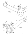
- FIGS 1 and 2 show front and rear perspective views of a conditioning air feeder for glove compartments of automobiles, made up according to the invention.
- This feeder is made up of a conduit 1, preferably of a flexible nature, which has fixed at one of its ends a bayonet coupling 2, by means of which the feeder will be connected to a mouth of the casing of the air conditioning equipment, whereas at the opposite end it has fixed thereto a coupling part 3 through which the conduit 1 is connected to the glove compartment of the automobile.
- the coupling part 3 consists of a receptacle 4 the open base 5 of which defines the connection mouth for connecting to the glove compartment, as will be set forth below. From this receptacle 4 there projects a nipple 6, Figure 5 , for connecting it to the conduit 1. Arms also project from the receptacle 4, two upper arms which are referenced with the number 7 and one lower arm which is referenced with the number 8, which arms are directed towards the casing of the air conditioning equipment and have at their end fixing elements for fixing on anchors formed externally in the casing of the air conditioning equipment, coinciding in position and number.
- the fixing elements for fixing the coupling part 3 consist of male pins 9 and 10 formed at the free end of the arms 7 and 8, respectively.
- the male pins 9 are shown in detail in Figure 3 and are finished in a transverse broadening 11 with a semi-arrowhead profile.
- the pins 9 are within a wall or slot 12 with inner partitions 13 which will serve, together with the pin 9 as fixing elements for fixing on anchors of the casing of the air conditioning equipment.
- Figure 4 shows a perspective view of the lower arm 8 having, like the upper arms 7, a pin 9' finished in a transverse rib 11' with a semi-arrowhead profile.
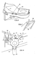
- FIG. 6 shows the casing 15 of the air conditioning equipment, in which the bayonet coupling 2 forming part of the air feeder shown in Figures 1 and 2 is installed.
- anchors 16 and 17 are formed, configured like female pins to receive the coupling and fixing of the male pins 9 and 9' of the arms 7 and 8 of the coupling part 3.
- Figure 7 shows in perspective view of one of the female pins 16, which is limited on one side by longitudinal walls 18, between which the male pin 9 of the coupling part will penetrate, and further has a transverse window 19 which will receive the rib 11 of the male pin 9, as will be set forth below.
- Figure 8 shows a front perspective view of the air feeder 3 of the invention coupled and fixed on the casing 15 of the air conditioning equipment.
- the female pin 17 of the casing 15 of the air conditioning equipment is configured like two consecutive flanges 20 and 21, the first of which serves as a guiding means to drive the coupling of the arm 9' of the pin 8, whereas the second serves as an element for retaining the end rib 11' of said arm, a clip-fastening being achieved as a result of the possibility of buckling of the pin 9', so that the rib 11' surpasses the edge of the flange 21.
- Figure 9 also shows how the open base 5 of the receptacle 4 is opposite an opening 22 of the wall 23 of the glove compartment, with the interposition of a foam ring 24 serving as a closing or tightness element between the coupling part 3 and the wall of the glove compartment 23, and also to absorb possible clearances between these components.
- a closing and opening gate 25 in the form of a rotating crown.
- Figure 10 which is a section according to section line X-X of Figure 8 , shows a section view of the coupling of the male pin 9 of the upper arms 7 of the coupling part in the female pin 16 of the casing 15 of the air conditioning equipment.
- This female pin 16 is within the slot limited by the walls 12, Figure 3 , between them and the inner partitions 13, at the same time as the pin 9 penetrates under the female pin 16 until the end rib 11 is housed in the window 19 of said female pin.
- the operation for assembling the air feeder of the invention therefore requires the connection of the conduit 1 to the casing of the air conditioning equipment, which is carried out by means of a bayonet coupling 2 with a makeup known in itself, and by means of fixing the coupling part 3 to the same casing 15 of the air conditioning equipment, by means of the pins 9 and 9' of the arms 7 and 8 of the coupling part which are clip-fastened in the female pins 16 and 17 of the casing of the air conditioning equipment, screws or auxiliary anchoring elements therefore not being necessary.
- the assembly of the conduit providing the conditioning air to the glove compartment is simplified and the risks of clearance between said feeder and glove compartment are reduced.
Landscapes
- Physics & Mathematics (AREA)
- Thermal Sciences (AREA)
- Engineering & Computer Science (AREA)
- Mechanical Engineering (AREA)
- Air-Conditioning For Vehicles (AREA)
Abstract
Description
- The present invention relates to a conditioning air feeder for glove compartments of automobiles, especially designed to cool the glove compartment and articles contained therein, from the air conditioning equipment of the automobile.
- Glove compartments cooled from the air conditioning equipment of the automobile are already known.
- In some cases the cooling of the glove compartment is achieved by passing the air conditioning circuit of the automobile behind the glove compartment, close thereto. With this system only a slight cooling of the interior of the glove compartment is achieved.
- To achieve a greater cooling effect in the glove compartment it is already known to connect the glove compartment to the air conditioning equipment by means of a conduit, through which part of the air supplied by said equipment to the glove compartment is diverted. This solution allows achieving greater cooling within the glove compartment, but has problems for assembling and coupling the intercommunication conduit. This conduit is connected at one end to the feeder equipment and at the opposite end to the glove compartment. The connection to the air conditioning equipment is usually carried out by means of a bayonet coupling. The connection to the glove compartment is carried out by means of a coupling part forming a nipple, through which it is connected to the conduit, and a mouth adaptable to an opening of the glove compartment, which opening can have assembled thereto a gate to open and close the passage of air between the mouth of the coupling part and the opening of the wall of the glove compartment.
- The mentioned conduit is supported through the coupling part, for which said part usually has tabs with holes through which anchor screws for anchoring to the dashboard of the vehicle pass.
- This solution forces carrying out fixing operations by means of screws, which makes the assembly more expensive. In addition, upon carrying out the anchoring to a different component of the glove compartment and of the air conditioning equipment, there is more risk of unwanted clearances occurring due to deviations, vibrations or movements of the mentioned components.
- The object of the present invention is to eliminate the problems set forth by means of a conditioning air feeder for the glove compartment of an automobile, which does not require fixing operations for fixing by means of screws and which eliminates or reduces the risk of clearances between the air conditioning equipment and the glove compartment.
- The air feeder of the invention is of the type set forth above, made up of a conduit which is connected at one end to the air conditioning equipment, for example by means of a bayonet coupling, and at the other end to the glove compartment, by means of a coupling part forming a nipple for inserting into the conduit and a connection mouth for connecting with the glove compartment.
- Based on this makeup, the feeder of the invention is characterised in that the coupling part, which is used as a connection means between the conduit and glove compartment, externally has fixing elements for fixing on anchors formed externally in the casing of the air conditioning equipment, coinciding in position and number. The mentioned anchoring and fixing elements have mutual clip-fastening means.
- With this makeup the air feeder is supported by the casing of the air conditioning equipment, i.e., by one of the components forming part of the air conditioning installation of the glove compartment, thus eliminating risks of tolerances between the air conditioner and the glove compartment.
- In addition, upon fastening the feeder to the casing of the air conditioning equipment by means of clipping, the fixing operation is simplified and the need to use screws or other auxiliary securing elements is eliminated.
- The coupling part forming part of the air feeder of the invention is made up of a receptacle from which the nipple for inserting into the conduit of said feeder starts. The open base of the receptacle forms the connection mouth for connecting to the opening of the glove compartment.
- The fixing elements for fixing the coupling part to the casing of the air conditioning equipment consist of arms projecting externally from the wall of the receptacle forming said coupling part, which arms are directed towards the casing of the air conditioning equipment and have at their ends a male pin, with a retaining tip, which is introduced and fixed in the anchors of the casing, which anchors are configured like female pins.
- The retaining tip of the male pins consists of a transverse broadening, with a semi-arrowhead profile, finishing the male pins on one side. With regard to the anchors of the casing of the air conditioning equipment, they consist of female pins formed externally in said casing, in which the male pins are tightly coupled by sliding and have a recess or transverse window positioned and sized to receive and fasten the retaining tip of these male pins.
- With the makeup described, to assemble the air feeder of the invention, it is connected to the casing of the air conditioning equipment by known systems, for example by means of a bayonet coupling and then the coupling part of the feeder is fixed to the actual casing of the air conditioning equipment, introducing the male pins into the female pins by sliding, until reaching the clipping or fixing position, the open base of the receptacle of the coupling part being opposite the opening of the casing of the glove compartment in this situation, with the interposition of a foam ring or the like, whereby the tightness of this connection and at the same time a shock-absorbing effect between the coupling part and the casing of the glove compartment is achieved.
- The attached drawings show a non-limiting embodiment, the description of which will aid to better understand the features and advantages of the feeder of the invention.
- In the drawings:
-
Figure 1 is a perspective view of an air feeder made up according to the invention. -
Figure 2 is a rear perspective view of the same feeder. -
Figure 3 shows detail A ofFigure 2 , on a larger scale. -
Figure 4 shows detail B ofFigure 2 , on a larger scale. -
Figure 5 is a partial longitudinal section view of the feeder of the invention, taken according to section line V-V ofFigure 2 . -
Figure 6 shows a perspective view of the casing of the air conditioning equipment, with the anchors for fixing the feeder of the invention. -
Figure 7 shows detail C ofFigure 6 , on a larger scale. -
Figure 8 shows a perspective view of the air feeder assembled in the casing of the air conditioning equipment ofFigure 6 . -
Figure 9 is a schematic section view of the air feeder assembled on the casing of the air conditioning equipment, taken according to section line IX-IX ofFigure 8 . -
Figure 10 shows a section view, taken according to section line X-X ofFigure 8 , of the coupling and fastening of the fixing elements of the feeder in the anchors of the casing of the air conditioning equipment. -
Figures 1 and 2 show front and rear perspective views of a conditioning air feeder for glove compartments of automobiles, made up according to the invention. This feeder is made up of aconduit 1, preferably of a flexible nature, which has fixed at one of its ends abayonet coupling 2, by means of which the feeder will be connected to a mouth of the casing of the air conditioning equipment, whereas at the opposite end it has fixed thereto acoupling part 3 through which theconduit 1 is connected to the glove compartment of the automobile. - The
coupling part 3 consists of areceptacle 4 theopen base 5 of which defines the connection mouth for connecting to the glove compartment, as will be set forth below. From thisreceptacle 4 there projects anipple 6,Figure 5 , for connecting it to theconduit 1. Arms also project from thereceptacle 4, two upper arms which are referenced with thenumber 7 and one lower arm which is referenced with thenumber 8, which arms are directed towards the casing of the air conditioning equipment and have at their end fixing elements for fixing on anchors formed externally in the casing of the air conditioning equipment, coinciding in position and number. - The fixing elements for fixing the
coupling part 3 consist ofmale pins 9 and 10 formed at the free end of thearms - The
male pins 9 are shown in detail inFigure 3 and are finished in atransverse broadening 11 with a semi-arrowhead profile. Thepins 9 are within a wall orslot 12 withinner partitions 13 which will serve, together with thepin 9 as fixing elements for fixing on anchors of the casing of the air conditioning equipment. -
Figure 4 shows a perspective view of thelower arm 8 having, like theupper arms 7, a pin 9' finished in a transverse rib 11' with a semi-arrowhead profile. -
Figure 6 shows thecasing 15 of the air conditioning equipment, in which thebayonet coupling 2 forming part of the air feeder shown inFigures 1 and 2 is installed. In thiscasing 15anchors male pins 9 and 9' of thearms coupling part 3. -
Figure 7 shows in perspective view of one of thefemale pins 16, which is limited on one side bylongitudinal walls 18, between which themale pin 9 of the coupling part will penetrate, and further has atransverse window 19 which will receive therib 11 of themale pin 9, as will be set forth below. -
Figure 8 shows a front perspective view of theair feeder 3 of the invention coupled and fixed on thecasing 15 of the air conditioning equipment. - In
Figure 9 the coupling of the pin 9' of thelower arm 8 can be coupled on thefemale pin 17 of thecasing 15 of the air conditioning equipment. - In this case the
female pin 17 of thecasing 15 of the air conditioning equipment is configured like twoconsecutive flanges pin 8, whereas the second serves as an element for retaining the end rib 11' of said arm, a clip-fastening being achieved as a result of the possibility of buckling of the pin 9', so that the rib 11' surpasses the edge of theflange 21. -
Figure 9 also shows how theopen base 5 of thereceptacle 4 is opposite anopening 22 of thewall 23 of the glove compartment, with the interposition of afoam ring 24 serving as a closing or tightness element between thecoupling part 3 and the wall of theglove compartment 23, and also to absorb possible clearances between these components. In the opening 22 of theglove compartment 23 there can be assembled a closing and openinggate 25, in the form of a rotating crown. -
Figure 10 , which is a section according to section line X-X ofFigure 8 , shows a section view of the coupling of themale pin 9 of theupper arms 7 of the coupling part in thefemale pin 16 of thecasing 15 of the air conditioning equipment. Thisfemale pin 16 is within the slot limited by thewalls 12,Figure 3 , between them and theinner partitions 13, at the same time as thepin 9 penetrates under thefemale pin 16 until theend rib 11 is housed in thewindow 19 of said female pin. - With the makeup described the
male pins 9 and 9' of thecoupling part 3 of the feeder are adjusted and retained in thefemale pins Figure 6 , of the casing of the air conditioning equipment, such that the entire air feeder is supported by said casing. - The operation for assembling the air feeder of the invention therefore requires the connection of the
conduit 1 to the casing of the air conditioning equipment, which is carried out by means of abayonet coupling 2 with a makeup known in itself, and by means of fixing thecoupling part 3 to thesame casing 15 of the air conditioning equipment, by means of thepins 9 and 9' of thearms female pins - With the air feeder of the invention the assembly of the conduit providing the conditioning air to the glove compartment is simplified and the risks of clearance between said feeder and glove compartment are reduced.
Claims (5)
- Conditioning air feeder for glove compartments of automobiles, made up of a conduit (1) which is connected at one end to the air conditioning equipment (15) by means of a bayonet coupling (2), and at the opposite end to the glove compartment 23 of the automobile by means of a coupling part (3) forming a nipple (6) for inserting into the conduit (1) and a connection mouth for connecting with the glove compartment, characterised in that the coupling part (3) externally has fixing elements for fixing on anchors formed externally in the casing (15) of the air conditioning equipment, coinciding in position and number, which anchoring and fixing elements have mutual clip-fastening means.
- The feeder according to claim 1, characterised in that the coupling part (3) this made up of a receptacle (4), from which the mentioned nipple (6) starts and the open base 5 of which forms the connection mouth for connecting to the glove compartment (23); and in that the mentioned fixing elements consist of arms (7 and 8) projecting externally from the wall of said receptacle 4, they are directed towards the casing >(15) of the air conditioning equipment and have at their ends a male pin (9-9') with a retaining tip which is introduced and fixed in the anchors of said casing.
- The feeder according to claim 2, characterised in that the retaining tip of the male pins (9 and 9') consist of a transverse broadening (11 and 11') with a semi-arrowhead profile and the anchors of the casing of the air conditioning equipment consist of female pins (16 and 17) formed externally in said casing, in which the male pins (9 and 9') are tightly coupled by sliding.
- The feeder according to claim 3, characterised in that the female pins (16) have longitudinal walls (18), which serve to drive the coupling of the male pins (9) and a recess or transverse window (19) in which the retaining tip (11) of said male pins (9) is fitted and fastened.
- The feeder according to claim 3, characterised in that one of the female pins (17) is made up of two parallel flanges (20 and 21), on the free edge of which the pin (9') of the arm (8) slides and the transverse rib (11') is retained.
Applications Claiming Priority (1)
| Application Number | Priority Date | Filing Date | Title |
|---|---|---|---|
| ES200702384U ES1066569Y (en) | 2007-11-20 | 2007-11-20 | AIR FEEDER AIR CONDITIONING TO CAR GUIDERS. |
Publications (2)
| Publication Number | Publication Date |
|---|---|
| EP2062759A1 true EP2062759A1 (en) | 2009-05-27 |
| EP2062759B1 EP2062759B1 (en) | 2010-05-26 |
Family
ID=38961741
Family Applications (1)
| Application Number | Title | Priority Date | Filing Date |
|---|---|---|---|
| EP08380321A Not-in-force EP2062759B1 (en) | 2007-11-20 | 2008-11-19 | Conditioning air feeder for glove compartments of automobiles |
Country Status (3)
| Country | Link |
|---|---|
| EP (1) | EP2062759B1 (en) |
| DE (1) | DE602008001356D1 (en) |
| ES (2) | ES1066569Y (en) |
Cited By (1)
| Publication number | Priority date | Publication date | Assignee | Title |
|---|---|---|---|---|
| EP3098100A1 (en) * | 2015-05-27 | 2016-11-30 | REHAU AG + Co | Air guidance system for a motor vehicle and method for producing an air guidance system for a motor vehicle |
Citations (3)
| Publication number | Priority date | Publication date | Assignee | Title |
|---|---|---|---|---|
| US3757851A (en) * | 1971-09-03 | 1973-09-11 | O Marble | Air conditioning converter accessory for motor vehicles |
| GB2346961A (en) * | 1999-02-10 | 2000-08-23 | Ford Motor Co | Moulded air duct with integral attachment member |
| EP1645447A1 (en) * | 2004-10-06 | 2006-04-12 | DENSO THERMAL SYSTEMS S.p.A. | Condensate draining hose for vehicle air conditioning systems |
-
2007
- 2007-11-20 ES ES200702384U patent/ES1066569Y/en not_active Expired - Fee Related
-
2008
- 2008-11-19 EP EP08380321A patent/EP2062759B1/en not_active Not-in-force
- 2008-11-19 ES ES08380321T patent/ES2346824T3/en active Active
- 2008-11-19 DE DE602008001356T patent/DE602008001356D1/en active Active
Patent Citations (3)
| Publication number | Priority date | Publication date | Assignee | Title |
|---|---|---|---|---|
| US3757851A (en) * | 1971-09-03 | 1973-09-11 | O Marble | Air conditioning converter accessory for motor vehicles |
| GB2346961A (en) * | 1999-02-10 | 2000-08-23 | Ford Motor Co | Moulded air duct with integral attachment member |
| EP1645447A1 (en) * | 2004-10-06 | 2006-04-12 | DENSO THERMAL SYSTEMS S.p.A. | Condensate draining hose for vehicle air conditioning systems |
Cited By (1)
| Publication number | Priority date | Publication date | Assignee | Title |
|---|---|---|---|---|
| EP3098100A1 (en) * | 2015-05-27 | 2016-11-30 | REHAU AG + Co | Air guidance system for a motor vehicle and method for producing an air guidance system for a motor vehicle |
Also Published As
| Publication number | Publication date |
|---|---|
| ES1066569U (en) | 2008-02-01 |
| DE602008001356D1 (en) | 2010-07-08 |
| EP2062759B1 (en) | 2010-05-26 |
| ES2346824T3 (en) | 2010-10-20 |
| ES1066569Y (en) | 2008-05-01 |
Similar Documents
| Publication | Publication Date | Title |
|---|---|---|
| CN107771134B (en) | Air-conditioning systems for vehicles, in particular roof-mounted air-conditioning systems and vehicles with air-conditioning systems of this type | |
| US20120235444A1 (en) | Roof hvac outlet | |
| US6340169B1 (en) | Hand grip bracket and assembly comprising a hand grip bracket and a head side gas bag module | |
| JPH04262940A (en) | Fastening for mounting gas bag to receiving housing | |
| US6857681B2 (en) | Connecting structure of air duct of vehicular air conditioning unit | |
| CN114786983B (en) | Cooling module for a motor vehicle | |
| CN211942883U (en) | Device for vehicle | |
| CN110549826A (en) | Interior compartment component of vehicle | |
| CN105383264B (en) | Swinging radian heating ventilation air-conditioning air duct | |
| EP2062759B1 (en) | Conditioning air feeder for glove compartments of automobiles | |
| CN104006524B (en) | Air conditioner for vehicles | |
| US20050001441A1 (en) | Luggage loft assembly | |
| US8430193B2 (en) | Side converger for vehicle front face structure, corresponding front face structure, and method for assembling such a structure | |
| US10625690B2 (en) | Vehicle ceiling connecting arrangement | |
| JP2008184118A (en) | Grab box | |
| US8025559B2 (en) | Device for connecting air ducts, motor vehicle door, motor vehicle pillar and motor vehicle interior paneling | |
| CN111252232A (en) | Device for fastening a cabin side wall trim and a cabin light trim to a structural component of an aerospace vehicle | |
| US7922345B2 (en) | Rearview mirror assembly for a motor vehicle with an interior mountable bracket | |
| US12259072B2 (en) | Retainer for holding a line, fastening arrangement for fastening a line to a motor vehicle and method for fastening a line to a motor vehicle | |
| JP6182089B2 (en) | Instrument panel structure | |
| US20060049651A1 (en) | Fixing device for a handle | |
| US6210026B1 (en) | Light housing with pivot elements | |
| CN103935308A (en) | Clamshell acoustic insulator assembly for a passenger compartment of a vehicle | |
| CN211494266U (en) | Charging opening cover and electric vehicle with same | |
| JP2002248995A (en) | Interior equipment for vehicles |
Legal Events
| Date | Code | Title | Description |
|---|---|---|---|
| PUAI | Public reference made under article 153(3) epc to a published international application that has entered the european phase |
Free format text: ORIGINAL CODE: 0009012 |
|
| AK | Designated contracting states |
Kind code of ref document: A1 Designated state(s): AT BE BG CH CY CZ DE DK EE ES FI FR GB GR HR HU IE IS IT LI LT LU LV MC MT NL NO PL PT RO SE SI SK TR |
|
| AX | Request for extension of the european patent |
Extension state: AL BA MK RS |
|
| GRAP | Despatch of communication of intention to grant a patent |
Free format text: ORIGINAL CODE: EPIDOSNIGR1 |
|
| 17P | Request for examination filed |
Effective date: 20091105 |
|
| RIN1 | Information on inventor provided before grant (corrected) |
Inventor name: DEMERS, MARCC/O SEAT S.A. Inventor name: VILLAR MESA, EVAC/O SEAT S.A. Inventor name: PEREZ PEREZ, FERNANDOC/O SEAT S.A. |
|
| AKX | Designation fees paid |
Designated state(s): DE ES FR GB IT |
|
| GRAS | Grant fee paid |
Free format text: ORIGINAL CODE: EPIDOSNIGR3 |
|
| GRAA | (expected) grant |
Free format text: ORIGINAL CODE: 0009210 |
|
| AK | Designated contracting states |
Kind code of ref document: B1 Designated state(s): DE ES FR GB IT |
|
| REG | Reference to a national code |
Ref country code: GB Ref legal event code: FG4D |
|
| REF | Corresponds to: |
Ref document number: 602008001356 Country of ref document: DE Date of ref document: 20100708 Kind code of ref document: P |
|
| REG | Reference to a national code |
Ref country code: ES Ref legal event code: FG2A Ref document number: 2346824 Country of ref document: ES Kind code of ref document: T3 |
|
| PLBE | No opposition filed within time limit |
Free format text: ORIGINAL CODE: 0009261 |
|
| STAA | Information on the status of an ep patent application or granted ep patent |
Free format text: STATUS: NO OPPOSITION FILED WITHIN TIME LIMIT |
|
| 26N | No opposition filed |
Effective date: 20110301 |
|
| REG | Reference to a national code |
Ref country code: DE Ref legal event code: R097 Ref document number: 602008001356 Country of ref document: DE Effective date: 20110228 |
|
| PGFP | Annual fee paid to national office [announced via postgrant information from national office to epo] |
Ref country code: IT Payment date: 20101130 Year of fee payment: 3 |
|
| GBPC | Gb: european patent ceased through non-payment of renewal fee |
Effective date: 20121119 |
|
| PG25 | Lapsed in a contracting state [announced via postgrant information from national office to epo] |
Ref country code: IT Free format text: LAPSE BECAUSE OF NON-PAYMENT OF DUE FEES Effective date: 20121119 |
|
| PG25 | Lapsed in a contracting state [announced via postgrant information from national office to epo] |
Ref country code: GB Free format text: LAPSE BECAUSE OF NON-PAYMENT OF DUE FEES Effective date: 20121119 |
|
| PGFP | Annual fee paid to national office [announced via postgrant information from national office to epo] |
Ref country code: FR Payment date: 20131129 Year of fee payment: 6 |
|
| REG | Reference to a national code |
Ref country code: FR Ref legal event code: ST Effective date: 20150731 |
|
| PG25 | Lapsed in a contracting state [announced via postgrant information from national office to epo] |
Ref country code: FR Free format text: LAPSE BECAUSE OF NON-PAYMENT OF DUE FEES Effective date: 20141201 |
|
| PGFP | Annual fee paid to national office [announced via postgrant information from national office to epo] |
Ref country code: DE Payment date: 20170131 Year of fee payment: 9 |
|
| PGFP | Annual fee paid to national office [announced via postgrant information from national office to epo] |
Ref country code: ES Payment date: 20171222 Year of fee payment: 10 |
|
| REG | Reference to a national code |
Ref country code: DE Ref legal event code: R119 Ref document number: 602008001356 Country of ref document: DE |
|
| PG25 | Lapsed in a contracting state [announced via postgrant information from national office to epo] |
Ref country code: DE Free format text: LAPSE BECAUSE OF NON-PAYMENT OF DUE FEES Effective date: 20180602 |
|
| REG | Reference to a national code |
Ref country code: ES Ref legal event code: FD2A Effective date: 20200103 |
|
| PG25 | Lapsed in a contracting state [announced via postgrant information from national office to epo] |
Ref country code: ES Free format text: LAPSE BECAUSE OF NON-PAYMENT OF DUE FEES Effective date: 20181120 |