EP2062377B1 - Adaptives verfahren zum senden und empfangen eines signals in einem mehrantennensystem, entsprechende sende- und empfangsgeräte, computerprogramm und signal - Google Patents
Adaptives verfahren zum senden und empfangen eines signals in einem mehrantennensystem, entsprechende sende- und empfangsgeräte, computerprogramm und signal Download PDFInfo
- Publication number
- EP2062377B1 EP2062377B1 EP07848227.0A EP07848227A EP2062377B1 EP 2062377 B1 EP2062377 B1 EP 2062377B1 EP 07848227 A EP07848227 A EP 07848227A EP 2062377 B1 EP2062377 B1 EP 2062377B1
- Authority
- EP
- European Patent Office
- Prior art keywords
- transmission
- antennas
- distribution
- signal
- transmission channel
- Prior art date
- Legal status (The legal status is an assumption and is not a legal conclusion. Google has not performed a legal analysis and makes no representation as to the accuracy of the status listed.)
- Active
Links
- 230000005540 biological transmission Effects 0.000 title claims description 197
- 238000000034 method Methods 0.000 title claims description 61
- 238000004590 computer program Methods 0.000 title claims description 11
- 230000003044 adaptive effect Effects 0.000 title description 3
- 238000009826 distribution Methods 0.000 claims description 91
- 239000011159 matrix material Substances 0.000 claims description 11
- 238000004458 analytical method Methods 0.000 claims description 7
- 238000004891 communication Methods 0.000 claims description 7
- 238000005192 partition Methods 0.000 description 45
- 230000006978 adaptation Effects 0.000 description 21
- 230000000875 corresponding effect Effects 0.000 description 18
- 230000006870 function Effects 0.000 description 14
- 238000012545 processing Methods 0.000 description 13
- 238000013139 quantization Methods 0.000 description 6
- 230000000737 periodic effect Effects 0.000 description 5
- 230000008901 benefit Effects 0.000 description 4
- 230000002596 correlated effect Effects 0.000 description 4
- 230000004048 modification Effects 0.000 description 4
- 238000012986 modification Methods 0.000 description 4
- 238000000638 solvent extraction Methods 0.000 description 4
- 241001080024 Telles Species 0.000 description 3
- 230000015556 catabolic process Effects 0.000 description 3
- 238000006731 degradation reaction Methods 0.000 description 3
- 238000005562 fading Methods 0.000 description 3
- 238000005457 optimization Methods 0.000 description 3
- 230000001629 suppression Effects 0.000 description 3
- 238000012360 testing method Methods 0.000 description 3
- 238000013459 approach Methods 0.000 description 2
- 238000012550 audit Methods 0.000 description 2
- 230000008859 change Effects 0.000 description 2
- 230000009849 deactivation Effects 0.000 description 2
- 238000001514 detection method Methods 0.000 description 2
- 230000010363 phase shift Effects 0.000 description 2
- 238000011002 quantification Methods 0.000 description 2
- 230000003595 spectral effect Effects 0.000 description 2
- 230000002087 whitening effect Effects 0.000 description 2
- AYCPARAPKDAOEN-LJQANCHMSA-N N-[(1S)-2-(dimethylamino)-1-phenylethyl]-6,6-dimethyl-3-[(2-methyl-4-thieno[3,2-d]pyrimidinyl)amino]-1,4-dihydropyrrolo[3,4-c]pyrazole-5-carboxamide Chemical compound C1([C@H](NC(=O)N2C(C=3NN=C(NC=4C=5SC=CC=5N=C(C)N=4)C=3C2)(C)C)CN(C)C)=CC=CC=C1 AYCPARAPKDAOEN-LJQANCHMSA-N 0.000 description 1
- 230000004913 activation Effects 0.000 description 1
- 230000001174 ascending effect Effects 0.000 description 1
- 230000001143 conditioned effect Effects 0.000 description 1
- 238000012217 deletion Methods 0.000 description 1
- 230000037430 deletion Effects 0.000 description 1
- 238000010586 diagram Methods 0.000 description 1
- 230000004907 flux Effects 0.000 description 1
- 230000006872 improvement Effects 0.000 description 1
- 230000009467 reduction Effects 0.000 description 1
- 238000011160 research Methods 0.000 description 1
- 230000000717 retained effect Effects 0.000 description 1
- 238000009827 uniform distribution Methods 0.000 description 1
Images


Classifications
-
- H—ELECTRICITY
- H04—ELECTRIC COMMUNICATION TECHNIQUE
- H04B—TRANSMISSION
- H04B7/00—Radio transmission systems, i.e. using radiation field
- H04B7/02—Diversity systems; Multi-antenna system, i.e. transmission or reception using multiple antennas
- H04B7/04—Diversity systems; Multi-antenna system, i.e. transmission or reception using multiple antennas using two or more spaced independent antennas
- H04B7/0413—MIMO systems
- H04B7/0426—Power distribution
- H04B7/0434—Power distribution using multiple eigenmodes
- H04B7/0447—Power distribution using multiple eigenmodes utilizing uniform distribution
-
- H—ELECTRICITY
- H04—ELECTRIC COMMUNICATION TECHNIQUE
- H04B—TRANSMISSION
- H04B7/00—Radio transmission systems, i.e. using radiation field
- H04B7/02—Diversity systems; Multi-antenna system, i.e. transmission or reception using multiple antennas
- H04B7/04—Diversity systems; Multi-antenna system, i.e. transmission or reception using multiple antennas using two or more spaced independent antennas
- H04B7/06—Diversity systems; Multi-antenna system, i.e. transmission or reception using multiple antennas using two or more spaced independent antennas at the transmitting station
- H04B7/0602—Diversity systems; Multi-antenna system, i.e. transmission or reception using multiple antennas using two or more spaced independent antennas at the transmitting station using antenna switching
- H04B7/0608—Antenna selection according to transmission parameters
- H04B7/061—Antenna selection according to transmission parameters using feedback from receiving side
-
- H—ELECTRICITY
- H04—ELECTRIC COMMUNICATION TECHNIQUE
- H04L—TRANSMISSION OF DIGITAL INFORMATION, e.g. TELEGRAPHIC COMMUNICATION
- H04L1/00—Arrangements for detecting or preventing errors in the information received
- H04L1/0001—Systems modifying transmission characteristics according to link quality, e.g. power backoff
- H04L1/0023—Systems modifying transmission characteristics according to link quality, e.g. power backoff characterised by the signalling
- H04L1/0025—Transmission of mode-switching indication
-
- H—ELECTRICITY
- H04—ELECTRIC COMMUNICATION TECHNIQUE
- H04L—TRANSMISSION OF DIGITAL INFORMATION, e.g. TELEGRAPHIC COMMUNICATION
- H04L1/00—Arrangements for detecting or preventing errors in the information received
- H04L1/0001—Systems modifying transmission characteristics according to link quality, e.g. power backoff
- H04L1/0002—Systems modifying transmission characteristics according to link quality, e.g. power backoff by adapting the transmission rate
- H04L1/0003—Systems modifying transmission characteristics according to link quality, e.g. power backoff by adapting the transmission rate by switching between different modulation schemes
-
- H—ELECTRICITY
- H04—ELECTRIC COMMUNICATION TECHNIQUE
- H04L—TRANSMISSION OF DIGITAL INFORMATION, e.g. TELEGRAPHIC COMMUNICATION
- H04L1/00—Arrangements for detecting or preventing errors in the information received
- H04L1/0001—Systems modifying transmission characteristics according to link quality, e.g. power backoff
- H04L1/0009—Systems modifying transmission characteristics according to link quality, e.g. power backoff by adapting the channel coding
-
- H—ELECTRICITY
- H04—ELECTRIC COMMUNICATION TECHNIQUE
- H04L—TRANSMISSION OF DIGITAL INFORMATION, e.g. TELEGRAPHIC COMMUNICATION
- H04L1/00—Arrangements for detecting or preventing errors in the information received
- H04L1/0001—Systems modifying transmission characteristics according to link quality, e.g. power backoff
- H04L1/0023—Systems modifying transmission characteristics according to link quality, e.g. power backoff characterised by the signalling
- H04L1/0026—Transmission of channel quality indication
-
- H—ELECTRICITY
- H04—ELECTRIC COMMUNICATION TECHNIQUE
- H04L—TRANSMISSION OF DIGITAL INFORMATION, e.g. TELEGRAPHIC COMMUNICATION
- H04L1/00—Arrangements for detecting or preventing errors in the information received
- H04L1/02—Arrangements for detecting or preventing errors in the information received by diversity reception
- H04L1/06—Arrangements for detecting or preventing errors in the information received by diversity reception using space diversity
- H04L1/0618—Space-time coding
- H04L1/0631—Receiver arrangements
Definitions
- the field of the invention is that of digital communications. More specifically, the invention relates to the transmission and reception of signals in the context of multiple-input multiple-output (MIMO) type multi-antenna systems ("Multiple Multiple Input Multiple Output").
- MIMO multiple-input multiple-output
- the invention finds particular applications in the field of radiocommunications, in systems has frequency selective transmission channels (single-carrier systems) or non-selective frequency (multi-carrier type systems).
- the invention is at the level of the physical layer of multi-antenna mobile access networks, and can be applied to uplink communications (from a terminal to a base station), as well as to downlink communications (from a base station to a terminal).
- the techniques for transmitting / receiving digital signals in systems comprising multiple antennas have many advantages, especially for mobile access networks. Indeed, such techniques allow an increase in a transmission rate, a capacity, or even a robustness of these multi-antenna systems, without requiring an increase in transmission power or frequency bands. allocated.
- the technique noted SIC-PARC for “Successive Interference Cancellation - PARC" makes it possible to transmit independent data streams, which may have different yields, on each of the transmit antennas of a multi-antenna system.
- the power supplied to the transmission can be uniformly distributed between all the transmitting antennas.
- the SINR signal-to-interference-plus-noise ratio associated with each of the transmit antennas is determined from an estimate of the transmission channel. transmission.
- a receiver knowing a family of modulation and coding schemes available for transmission can determine the modulation and coding techniques to be used in transmission in order to minimize the difference with the theoretical performances, and transmit these elements to the transmitter thanks to a piece of information. from the receiver, also called “instantaneous partial feedback", for example by spawning a CQI message ("Channel Quality Indicator” for "indicator quality of the channel ").
- the emission standard considered makes it possible to define a family of MCS modulation and coding schemes, and thus of discrete yields, enabling a receiver to determine the MCSs, and thus the discrete yields per antenna, to be used.
- S-PARC Selective Per Antenna Rate Control
- the number of independent streams transmitted is less than or equal to the total number of transmitting antennas
- the selection of the transmit antennas can be done according to the quality of the transmission channel and / or the correlation of the transmit antennas, so as to maximize in particular the sum of the returns on all the streams, and therefore the overall capacity. of the system.
- the allocation of the discrete returns to each transmitting antenna is based on the reception of an CQI per antenna, indicating the discrete output per antenna (MCS) to be used.
- a receiver begins by estimating the transmission channel during a first step 61.
- the receiver determines the SINR ratio associated with each of the transmit antennas, and sends this information back to the receiver. transmitter ("feedback").
- the associated transmitter can then select (63) the active transmit antennas, and deduce from it the theoretical output to be used by antenna and the MCS modulation and coding to be used (64) to minimize the difference with the theoretical output.
- the transmitter transmits data packets from the active transmit antennas during a step 65.
- a disadvantage of this technique is that it does not take into account the set of discrete yields available on transmission when selecting active antennas. In practice, this technique therefore suffers from a quantization noise due to the family of discrete yields available. Therefore, the discretization of the theoretical yields subsequently applied (ie the choice of modulation scheme and MCS coding to be used to minimize the difference with the theoretical yield, among the MCS available) causes a loss of spectral efficiency.
- ST Chung et al. propose in the document "Approaching the MIMO Capacity with low-rate feed-back channel in V-BLAST” (Eurasip Journal on Applied Signal Processing, pages 762-771. ).
- MCS discrete yields
- This technique also uses an antenna-independent scalar type coding chosen to approach a maximum capacity defined by the Shannon limit, in particular in order to obtain a low bit error rate and thus maximize the overall capacity of the system. .
- the invention proposes a new solution that does not have all of these disadvantages of the prior art, in the form of a method of receiving a received signal, corresponding to a data signal transmitted by a transmitter to a destination.
- a receiver via a transmission channel, said transmitter comprising N T transmitting antennas and said receiver comprising N R receiving antennas, with N T and N R greater than or equal to 2.
- the invention proposes a technique making it possible to adapt a group distribution of the transmission antennas, as a function of information representative of the transmission channel, so as to optimize the transmission performance as a function, in particular, of the available code efficiencies. in program. It is thus considered a partitioning antennas in transmission, that is to say disjoint groups of transmit antennas, a group comprising at least one transmitting antenna.
- the reception method according to the invention therefore makes it possible to transmit to the transmitter a parameterization signal defining adaptation information, comprising at least a distribution in groups and the yields allocated to each group according to the different distributions, for choosing the values. these parameters in order to optimize the throughput (capacity), and / or robustness, etc., of the multi-antenna system.
- This setting signal is for example transmitted from the receiver to the transmitter ("feedback" of the receiver) by means of a CQI message.
- the transmitter which will select the most suitable distribution, reception of this parameterization signal.
- a change in the distribution of the transmit antennas can modify the transmission channel capacity values obtained for each group, and thus require the modification of certain transmit performance values in order to optimize the performance of the transmission antennas. transmission, while respecting the discreet returns available on the program.
- the antenna groups can be of distinct cardinality, that is, the different antenna groups do not necessarily include the same number of transmitting antennas.
- the maximum number of transmit antennas in a group should not exceed the number of receiving antennas.
- the number of transmitting antennas in a group is between 1 and N R.
- the invention proposes a system that takes into account the existence of a limitation on the number of code efficiencies available to the transmitter (set by the transmission standard under consideration) which aims to reduce the quantization noise.
- the analysis and transmission steps are also implemented periodically and / or as a function of a significant variation of said transmission channel, that is to say a variation greater than a predetermined threshold.
- the grouping of the transmitting antennas and the yields attributed to each group of antennas are thus adapted to optimally exploit the multi-antenna system.
- said determining step determines specific powers allocated respectively to each of said transmitting antennas, and said setting signal also defines these powers.
- Different adaptation information also called parameters, is thus adapted according to information representative of the transmission channel, and in particular the quality of this channel, so as to optimize the performance of the multi-antenna system.
- the reception method comprises a step of selecting transmission antennas among said N T transmit antennas, said active antennas, at least as a function of said representative information of the transmission channel. Said parametric signal then also defines the active antennas, that is to say includes information to identify the selected antennas.
- this antenna selection step can lead to the deactivation of the unselected transmission antennas.
- each transmission antenna of the multi-antenna system is scanned, and the antennas are deactivated, for example having too much correlation, or being associated with a highly noisy transmission channel, etc.
- This activation / deactivation of the transmit antennas is in particular implemented by to optimize the capacity of the multi-antenna system.
- the parameterization signal may define a group comprising all the deactivated transmit antennas, and define a null efficiency assigned to this group of transmit antennas.
- the antenna selection algorithm may suggest using all available transmit antennas, i.e. N T transmit antennas.
- the selection step is carried out jointly with said determination step.
- the step of selecting the active transmit antennas takes into account at least some adaptation information and vice versa.
- the joint optimization of the selection of antennas and the adaptation of the yields makes it possible in particular to avoid a significant degradation of the overall capacity of the multi-antenna system, due to the discretization of the emission efficiencies.
- the grouping of transmit antennas is adapted during transmission, for example to better monitor the variations of the transmission channel.
- the optimal partition is then chosen so as to respect essential hardware constraints, such as a low decoding complexity, a minimum “feedback" between the receiver and the transmitter, and so on.
- the reception method implements a step of determining an order of said groups, and a decoding step implemented successively for each group following said scheduling.
- a change in the grouping of transmit antennas requires a modification of the scheduling.
- said scheduling minimizes a metric taking into account the group distributions of said transmit antennas and / or the powers provided by said transmit antennas and / or specific yields and / or a decoding order.
- Another aspect of the invention relates to a method of transmitting a data signal from a transmitter to a receiver via a transmission channel, said transmitter comprising N T transmit antennas and said receiver comprising N R receiving antennas with N T and N R greater than or equal to 2.
- Such a transmission method is in particular adapted to receive a parameterization signal transmitted for example according to the reception method described above.
- this transmission method is adaptive and controlled by a "feedback" of the receiver, for example when updating the parameters defined in the parameterization signal.
- the invention in another embodiment, relates to a device for receiving a received signal, corresponding to a data signal transmitted by a transmitter via a transmission channel, said transmitter comprising N T transmit antennas and said transmission device.
- receiving comprising N R receiving antennas, with N T and N R greater than or equal to 2.
- Another aspect of the invention relates to a device for transmitting a data signal to a receiver via a transmission channel, said transmission device comprising N T transmitting antennas and said receiver comprising N R receiving antennas, with N T and N R greater than or equal to 2.
- Such an emission device is particularly suitable for implementing the transmission method described above.
- This is for example a base station, or a terminal type radiotelephone, laptop, personal assistant type PDA (in English "Personal Digital Assistant"), depending on whether one is link up or descending.
- Yet another embodiment of the invention relates to a computer program product downloadable from a communication network and / or recorded on a computer readable medium and / or executable by a processor, including program code instructions for the implementation of the reception method described above, and / or a computer program product downloadable from a communication network and / or recorded on a computer-readable and / or executable medium by a processor, comprising code instructions program for carrying out the transmission method described above.
- another aspect of the invention relates to a parameterizing signal of a transmitter, transmitted from a receiver to said transmitter via a transmission channel, said transmitter comprising N T transmitting antennas and said receiver comprising N R antennas with N T and N R greater than or equal to 2.
- Such a parameterization signal can in particular define, according to the reception method described above, various parameters or adaptation information implemented in transmission, such as the distribution of the transmit antennas in groups, the yields attributed to each of the groups, the selected antennas (active antennas), the powers allocated to each transmitting antenna, ...
- This parameterization signal may of course include the various characteristics relating to the reception method according to the invention.
- An adaptive distribution of the transmitting antennas is thus considered, that is to say that a feedback from the receiver to the transmitter to another ("feedback" receiver), the choice of partition can differ, thus making it possible to adapt to variations in the transmission channel.
- the "feedback" of the receiver can either comprise a single distribution in groups, and thus impose its choice on the transmitter, or include several possible distributions, and then leave the issuer the choice of optimized distribution among these distributions conceivable.
- the advantage of grouping the transmit antennas according to this particular embodiment of the invention lies in a better adaptation of the available yields given an optimized choice of distribution.
- the parameterization signal can also define the powers allocated per antenna, which allows a better adaptation to the available yields.
- the modification of the transmission powers then implies obtaining new capacity values for each group of antennas, which may require a modification of the scheduling (also called decoding order) chosen so as to maintain a system multi-antenna optimized.
- the parameterization signal can also define active and non-active antennas.
- one places oneself in a context of reduced feedback, while not considering the adaptation of the transmission powers.
- a predetermined power is considered, and equidistributed between the different transmit antennas (active), in the absence of knowledge of the transmission channel.
- a data signal is transmitted from a transmitter comprising N T transmit antennas to a receiver comprising N R receiving antennas via a transmission channel, with N T greater than or equal to 2 and N R greater than or equal to 2.
- the receiver determines a single distribution by groups of transmit antennas, and specific yields assigned to each group, according to information representative of the transmission channel (for example an estimate of the transmission channel). propagation channel or SNR (signal to noise) reports), and transmits this adaptation information to the transmitter by means of the parameterization signal.
- the maximum number of transmitting antennas in a group must not exceed the number of antennas active in reception. This constraint comes in particular from the whitening of the output of the MMSE vector detector.
- the efficiency of the space-time code includes the performance of the channel code and the order of the modulation chosen (for example, an ST-BICM using four transmit antennas and a 1/3 convolutional code with a QPSK modulation has an overall performance of 4 ⁇ 1 3 ⁇ 2 ).
- a detection (spatio-temporal) is proposed. flows associated with each group of transmit antennas based on a successive cancellation of interference.
- the invention is not limited to a detection of the MMSE type per group of antennas using a successive cancellation of interference, but assumes that the calculated group capacities come from a detector group any one, based on a successive interference cancellation, for which a capacity formula for each group can be obtained depending on the channel estimate.
- the invention finds applications in systems having frequency selective transmission channels (single-carrier type systems) as well as systems having non-frequency selective channels (multi-carrier type systems).
- a received signal 11 corresponding to the data signal transmitted after passing through the transmission channel, is considered.
- the received signal 11 is analyzed, so as to obtain at least one information 14 representative of the transmission channel.
- This information 14 corresponds for example to an estimation of the transmission channel between the transmitter and the receiver.
- This information 14 is notably used, during a second step 13, to construct a parameterization signal 15, making it possible to define a distribution of the N T transmit antennas in groups of antenna (s), and the specific efficiencies affected. respectively to each of the groups of antennas.
- the parameterization signal 15 is then transmitted to the transmitter of the MIMO system, for example in the form of a CQI message.
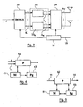
- FIG 7 illustrates in simplified form a receiving device comprising N R receiving antennas, according to this embodiment.
- This reception device comprises means for analyzing (71) the signal received, from an estimate of the transmission channel for example, means for determining (72) a distribution of the transmit antennas and specific efficiencies assigned to each group, and decoding means (73) of the packet transmitted.
- these determination means (72) jointly perform a selection of transmitting and / or receiving antennas, for deactivating certain transmitting and / or receiving antennas. More specifically, the subset of antennas active in transmission and / or reception is chosen from among all the possible combinations, so as to maximize for example the sum of the discrete capacity of the transmission system or the overall capacity (that is, say without taking into account the quantification of returns) of the system. Optimization is thus performed on all radio links.
- reception selection essentially makes it possible to reduce the complexity of the processing of the receiver.
- the adaptation information (such as the partitioning of the transmit antennas, the allocated powers, the efficiencies used in practice (less than or equal to those calculated) as well as the decoding order) are defined either in conjunction with the number of active antennas of the MIMO channel, ie once the number of active antennas determined.
- the correlated processing of these different information makes it possible in particular to reduce the quantization noise and thus to allow the increase of the performances in terms of spectral efficiency.
- the transmission power can in particular be predetermined and equidistributed between the different active transmit antennas.
- this adaptation information is then sent back to the transmitter in the form of a parameterization signal (CQI message).
- CQI message a parameterization signal
- the transmitter is then able to adapt to the optimal partition chosen, as well as the yields to be used for the transmission of a data packet.
- the decoding of the transmitted packet is implemented according to the decoding order chosen after the channel estimation and before transmission of the packet.
- figure 2 illustrates an exemplary structure of the parameterization signal 15.
- This signal comprises at least a first parameter field 1 , comprising information relating to a group distribution of the transmitting antennas, and a second parameter field 2 , comprising information relating to specific outputs assigned respectively to each of the groups of transmitting antennas.
- this parameterization signal 15 may also comprise a field 3 carrying information relating to specific powers allocated respectively to each of the transmitting antennas, or a field (not shown) carrying information relating to the active antennas of FIG. program.
- the figure 3 illustrates more precisely the operation on the transmission side. As illustrated on this figure 3 , the setting signal transmitted by the receiver is received by the transmitter of the multi-antenna system.
- the different fields of the signal of Parameters 15 are analyzed, so as to adapt the transmitter, by defining at least the distribution of transmit antennas by group and the yields associated with each group.
- the transmitter is in particular able to adapt to the partition for the moment of transmission t , as well as the returns per group.
- the control module 31 makes it possible to reconfigure a demultiplexer 32 into K outputs, and then to apply a space-time code module on each of these outputs.
- the control module 31 determines the transmit antennas applied to each group.
- the control module chooses for example ( N T 3 , N T 6 ) ⁇ 1 , (N T 1 , N T 2 ) ⁇ ⁇ 2 and ( N T 5 ) ⁇ ⁇ 3 , this distribution making it possible to optimize the performance of the multi-antenna system.
- the binary data stream at the input of the transmitter is first demultiplexed during a DEMUX stage 32, and converted into a number of independent streams K corresponding to the number of transmit antenna groups. defined in the parameterization signal 15 and extracted during the control step 31.
- the K streams are each separately encoded and mapped into an MCS modulation and modulation block 33 1 , ...., 33 K.
- the MCS blocks may be ST-MCS (Space-Time Modulation and Coding Scheme) type, for example space-time coding using ST-BICM type modulation. "Space Time Bit Interleaved Coded Modulation").
- the coding and modulation schemes 33 1 , .... 33 K controlled by the controller 31 taking into account the parameterization signal 15, thus make it possible to define specific efficiencies assigned respectively to each of the transmit antenna groups ⁇ 1 , ... ⁇ K. According to an alternative embodiment, these diagrams also make it possible to define specific powers allocated respectively to each of the transmitting antennas.
- coding and modulation blocks 33 1 ,..., 33 K are followed by a switch 34 (also called a demultiplexer) performing a bijection of all the data streams on all of the active antennas.
- a switch 34 also called a demultiplexer
- data decoding is performed per layer for each group ⁇ 1 ,..., ⁇ K of antennas.
- the first layer is detected vectorially (vector detector based for example on an MMSE criterion), and then decoded.
- the decoding order j may provide to decode the group ⁇ 1 during a first layer, and then to decode the group ⁇ K during a next layer.
- the signal After decoding a layer, the signal is re-encoded and then the interferences are regenerated and then subtracted from the received multiplexed signal. A vector successive interference suppression is thus performed.
- the maximum number of transmit antennas in a group must not exceed the number antennas active in reception. This constraint comes in particular from the whitening of the output of the MMSE vector detector.
- a first embodiment is considered below in which the determination of the adaptation information is performed after the selection of the active transmit antennas.
- ⁇ X 1 , ..., X M ⁇ be the set of partitions considered satisfying the following condition: ⁇ X , ⁇ ⁇ i ⁇ X where i ⁇ l K ⁇ we have ⁇ i ⁇ NOT R .
- C ⁇ i , j thus corresponds to the (continuous) efficiency obtained for the antenna group ⁇ t with respect to the decoding order j .
- R k i , j * ⁇ j is the yield chosen among the cardinality yields
- the metric M j , ⁇ is calculated from a metric F.
- This metric F is a function of the theoretical yields (which can take any value), conditioned by their capacity, itself a function of the power play ⁇ P 1 , ..., P N T allocated to each transmitting antenna and returns selected from those available.
- the choice of the returns is made by a minimization on both the power of emission and on the indices k allowing to choose the discrete yield closest to the theoretical one.
- the search for the minimum metric is thus carried out according to this embodiment on the set of permutations of the successive ordered decodings, on the set of power plays and on all the partitions to consider.
- the transmitter is informed of the chosen partition, and the choice of the yields to be used for each group of antennas belonging to the chosen partition.
- the decoding order does not need to be transmitted to the transmitter, since this information is only used at the receiver.
- the problem of the identification of the active antennas can be solved by widening the partition to the total number of antennas available on transmission, and by choosing a CQI associated with a null efficiency for the group comprising the inactive antennas.
- the metric F may take the form of a constrained Euclidean metric.
- Equation (8) is thus expressed more simply, since the minimization is carried out on each element of the partition with a permutation j fixed, whereas in the preceding situation (5) the minimization was carried out jointly on all the elements of the score.
- a second embodiment is considered hereinafter in which the determination of the adaptation information is performed together with the selection of the active transmission antennas.
- the selection of the active transmit antennas takes into account at least some adaptation information and vice versa.
- an algorithm for selecting active transmit antennas is described below, making it possible to jointly select a subset of n T transmission antennas from among the N T transmit antennas, a partition of transmission antennas. , an optimal decoding order, as well as optimized discrete yields (MCS) ( n T ⁇ N T ).
- the receiver performs, according to this second embodiment, during a step 82, a selection of the transmit antennas together with the choice of the partition, the decoding order, and the modulation and coding schemes.
- the receiver can know a MCS table to use (83), which it can use to build the parameterization signal.
- the setting signal is then transmitted to the transmitter (84).
- This joint processing can in particular be done in reception, in order to limit the number of CQI sent back to the transmitter, and thus to reduce the feedback.
- the selection of transmit antennas does not result in an increase in the amount of information in the return channel ("feedback" of the receiver), especially if the MCS of zero efficiency is included in the MCS table and if it is assumed that zero efficiency is assigned to the deactivated antennas.
- the MMSE-based receiver combined with successive interference subtraction with group efficiency control is optimal, assuming independent Gaussian inputs.
- the matrices A ⁇ i take a different form depending on the choice chosen for the receiver. Depending on the type of receiver considered, these matrices can be calculated thanks to the knowledge of the transmission channel in reception, or obtained by estimation on the pilot symbols.
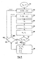
- the figure 9 presents an emission antenna selection algorithm, correlated to the adaptation of the yields.
- the antenna selection algorithm takes into account two inputs: information on the transmission channel (for example of the estimated transmission channel type), and a set of discrete output sets (table of MCS (possibly ST-MCS) to consider).
- variable R max corresponding to the maximum efficiency that can be achieved, is initialized to the value "0".
- the discretization of the flux capacity (that is to say the capacity for one of the groups of transmit antennas considered) on all (ST-) MCS available is realized in the selection algorithm thanks to the operator ⁇ ⁇ ⁇ (integer part), which makes it possible to choose the nearest MCS (or ST-MCS) by lower value.
- the power is considered fixed and, in the absence of transmission channel knowledge, equidistributed between all the active transmit antennas.
- each capacity per stream is conventionally calculated from matrix inversions, as in equation (14).
- B l + 1 B l - ⁇ d ⁇ B l ⁇ H ⁇ i + 1 I ⁇ i + 1 + ⁇ d ⁇ H ⁇ i + 1 ⁇ ⁇ B l ⁇ H ⁇ i + 1 - 1 ⁇ H ⁇ i + 1 ⁇ ⁇ B l
- the first algorithm described in relation to the figure 9 can be particularized and rewritten as a second algorithm.
- the first algorithm and the second algorithm (as well as those derived from it) can be simplified by searching only the optimal decoding order of the fixed partition.
- one of the embodiments relies on an iterative implementation starting from an empty set S.
- Another embodiment relies on an iterative implementation starting from a set S full, that is to say comprising the N T transmitting antennas. Indeed, the performance losses due to these iterative implementations are negligible.
- these two embodiments result in the same selection of the set S.
- the selected transmission antennas that is to say those chosen as activated, are added one by one to the set S.
- the transmission antenna selection algorithm relies on an iterative embodiment called “decremental”, that is to say starting with a set S of full transmit antennas including the N T antennas of emission, can be easily obtained from the previous incremental algorithm.
- the transmit antennas are subtracted one by one if the sum capacity of the set containing x antennas is greater than that containing x +1 antennas.
- the way of calculating the capabilities per antenna is performed in a manner similar to that described in relation to the first example, that is to say using a recursive method for obtaining the inverse matrices.
- a fixed decoding order is imposed by the way of adding the elements in the set S for an incremental type procedure.
- the decoding order is set during an initialization step. It may, for example, be based on a criterion for classifying the SINRs at the output of the MMSE before the suppression of interference; we test the suppression of the weakest at each iteration.
- An emission device comprises a memory 41 consisting of a buffer, a processing unit 42, equipped for example with a microprocessor ⁇ P, and driven by the computer program 43, implementing the transmission method according to the invention.
- the code instructions of the computer program 43 are for example loaded into a RAM memory before being executed by the processor of the processing unit 42.
- the processing unit 42 receives as input a stream binary data d , and a setting signal 15. for example in the form of a CQI message.
- the microprocessor of the processing unit 42 implements the steps of the transmission method described above, according to the instructions of the computer program 43, to adapt the distribution of the transmit antennas by group and assign specific yields to each one. groups, depending on the yields available in transmission, so as to optimize the transmission performance.
- the transmission device comprises means for receiving a parameterization signal transmitted by said receiver, means for selecting one of the distributions defined in the parameterization signal, means for distributing the transmitting antennas according to the groups of the selected distribution, and means for assigning to each of the groups the corresponding specific efficiency defined in the parameterization signal.
- the receiving device also comprises a memory 51, a processing unit 52, equipped for example with a microprocessor ⁇ P, and driven by the computer program 53, implementing the reception method according to the invention.
- the code instructions of the computer program 53 are for example loaded into a RAM before being executed by the processor of the processing unit 52.
- the processing unit 52 receives as input a signal received 11.
- the microprocessor of the processing unit 52 implements the steps of the reception method described above, according to the instructions of the computer program 53, to analyze the received signal and determine a signal parameterization device 15 defining at least one distribution of the antenna transmitting antenna groups (s) and specific efficiencies assigned respectively to each of the groups of antennas for each distribution, according to information representative of the transmission channel.
Claims (15)
- Verfahren zum Empfangen eines Empfangssignals (11), das einem Datensignal entspricht, das von einem an einen Empfänger gerichteten Sender über einen Übertragungskanal gesendet wird, wobei der Sender NT Sendeantennen umfasst und der Empfänger NR Empfangsantennen umfasst, wobei NT und NR größer oder gleich 2 sind,
dadurch gekennzeichnet, dass es die folgenden Schritte umfasst:- Analysieren (12) des empfangenen Signals, was eine den Übertragungskanal repräsentierende Information (14) ergibt;- Bestimmen auf periodische Weise oder als Funktion einer Veränderung des Übertragungskanals:· wenigstens einer Verteilung der Sendeantennen auf wenigstens eine Gruppe aus wenigstens einer Antenne als Funktion der den Übertragungskanal repräsentierenden Information und· der spezifischen Wirkungsgrade, die jeder der Gruppen von Antennen zukommen, für jede Verteilung als Funktion der den Übertragungskanal repräsentierenden Information;
wobei wenigstens eine Gruppe für wenigstens eine der Bestimmungen wenigstens zwei Sendeantennen umfasst;- Übertragen eines Parametrierungssignals (15), das die eine oder die mehreren Verteilungen und die spezifischen Wirkungsgrade definiert, an den Sender. - Empfangsverfahren nach Anspruch 1, dadurch gekennzeichnet, dass die Schritte des Analysierens und Übertragens ebenfalls auf periodische Weise und/oder als Funktion einer Veränderung des Übertragungskanals ausgeführt werden.
- Empfangsverfahren nach einem der Ansprüche 1 und 2, dadurch gekennzeichnet, dass der Bestimmungsschritt die spezifischen Leistungen, die jeder der Sendeantennen zugewiesen sind, bestimmt und dass das Parametrisierungssignal (15) auch diese Leistungen definiert.
- Empfangsverfahren nach einem der Ansprüche 1 bis 3, dadurch gekennzeichnet, dass es einen Schritt des Auswählens von Sendeantennen unter den NT Sendeantennen, den so genannten aktiven Antennen, wenigstens als Funktion der den Übertragungskanal repräsentierenden Information (14) umfasst,
und dass das Parametrisierungssignal (15) die aktiven Antennen definiert. - Empfangsverfahren nach Anspruch 4, dadurch gekennzeichnet, dass der Auswahlschritt gemeinsam mit dem Bestimmungsschritt ausgeführt wird.
- Empfangsverfahren nach einem der Ansprüche 4 und 5, dadurch gekennzeichnet, dass eine optimierte geordnete Verteilung Γ*, die spezifischen Wirkungsgrade pro Gruppe R* für diese Verteilung und eine optimierte Gesamtheit S* der aktiven Antennen anhand der folgenden Gleichungen bestimmt werden:


mit:


wobei:- H den Übertragungskanal repräsentiert;- ρ dem Signal/Rausch-Verhältnis entspricht;- {P1, ..., PNT} einem Satz Sendeleistungen, die zu jeder Sendeantenne gehören, entspricht;- J|Δ| einem Satz diskreter Wirkungsgrade, die beim Senden verfügbar sind, entspricht;- Δ einer Gruppe entspricht, die in der Verteilung Γ enthalten ist;- AΔ eine Matrix ist, die den Empfänger repräsentiert. - Empfangsverfahren nach einem der Ansprüche 1 bis 6, dadurch gekennzeichnet, dass wenigstens eine Verteilung unter Berücksichtigung wenigstens eines der Elemente bestimmt wird, die zu der Gruppe gehört, die umfasst:- diskrete Wirkungsgrade, die beim Senden verfügbar sind;- Leistungen, die jeder Verteilung auf Gruppen der Sendeantennen zugeordnet sind;- eine Reihenfolge der Decodierung, die auf Höhe des Empfängers ausgeführt wird;- die Anzahl NR von Empfangsantennen;- eine Anzahl aktiver Sendeantennen.
- Empfangsverfahren nach einem der Ansprüche 1 bis 7, dadurch gekennzeichnet, dass es einen Schritt des Bestimmens einer Reihung der Gruppen und einen Decodierungsschritt, der für jede Gruppe entsprechend der Reihung sukzessive ausgeführt wird, ausführt.
- Empfangsverfahren nach Anspruch 8, dadurch gekennzeichnet, dass die Reihung eine Metrik minimiert, die die Verteilungen auf Gruppen der Sendeantennen und/oder die von den Sendeantennen gelieferten Leistungen und/oder die spezifischen Wirkungsgrade und/oder eine Decodierungsreihenfolge berücksichtigt.
- Verfahren zum Senden eines Datensignals von einem Sender zu einem Empfänger über einen Übertragungskanal, wobei der Sender NT Sendeantennen umfasst und der Empfänger NR Empfangsantennen umfasst, wobei NT und NR größer oder gleich 2 sind,
dadurch gekennzeichnet, dass es die folgenden Schritte umfasst:- Empfangen eines Parametrisierungssignals (15), das von dem Empfänger übertragen wird, das definiert:die als Funktion einer den Übertragungskanal repräsentierenden Information durch Bestimmung auf periodische Weise oder als Funktion einer Veränderung des Übertragungskanals erhalten werden,• wenigstens eine Verteilung der Sendeantennen auf wenigstens eine Gruppe aus wenigstens einer Antenne und• spezifische Wirkungsgrade, die jeder der Gruppen von Antennen für jede Verteilung zukommen;
wobei wenigstens eine Gruppe für wenigstens eine Bestimmung wenigstens zwei Sendeantennen umfasst;- Auswählen einer der Verteilungen unter der einen oder den mehreren Verteilungen, die in dem Parametrisierungssignal (15) definiert sind;- Verteilen der Sendeantennen entsprechend den Gruppen der gewählten Verteilung;- Hinzufügen zu jeder der Gruppen des entsprechenden spezifischen Wirkungsgrades, der in dem Parametrisierungssignal (15) definiert ist. - Vorrichtung zum Empfangen eines empfangenen Signals (11), das einem Datensignal entspricht, das von einem Sender über einen Übertragungskanal gesendet wird, wobei der Sender NT Sendeantennen umfasst und die Empfangsvorrichtung NR Empfangsantennen umfasst, wobei NT und NR größer oder gleich 2 sind,
dadurch gekennzeichnet, dass sie Folgendes umfasst:- Mittel zum Analysieren des empfangenen Signals (11), was eine den Übertragungskanal repräsentierende Information (14) ergibt;- Mittel zum Bestimmen auf periodische Weise oder als Funktion einer Veränderung des Übertragungskanals:und• wenigstens einer Verteilung der Sendeantennen auf wenigstens eine Gruppe aus wenigstens einer Antennen als Funktion der den Übertragungskanal repräsentierenden Information• der spezifischen Wirkungsgrade, die jeder der Gruppen von Antennen zukommen, für jede Verteilung als Funktion der den Übertragungskanal repräsentierenden Information;wobei wenigstens eine Gruppe wenigstens zwei Sendeantennen für wenigstens eine der Bestimmungen umfasst;- Mittel zum Übertragen eines Parametrisierungssignals (15), das die eine oder die mehreren Verteilungen und die spezifischen Wirkungsgrade definiert, an den Sender. - Vorrichtung zum Senden eines Datensignals zu einem Empfänger über einen Übertragungskanal, wobei die Sendevorrichtung NT Sendeantennen umfasst und der Empfänger NR Empfangsantennen umfasst, wobei NT und NR größer oder gleich 2 sind,
dadurch gekennzeichnet, dass sie Folgendes umfasst:- Mittel zum Empfangen eines Parametrisierungssignals (15), das von dem Empfänger übertragen wird und definiert:die als Funktion einer den Übertragungskanal repräsentierenden Information durch Bestimmen auf periodische Weise oder als Funktion einer Veränderung des Übertragungskanals erhalten werden,• wenigstens eine Verteilung der Sendeantennen auf wenigstens eine Gruppe aus wenigstens einer Antenne und• spezifische Wirkungsgrade, die jeder der Gruppen von Antennen zukommen, für jede Verteilung;
wobei wenigstens eine Gruppe für wenigstens eine Bestimmung wenigstens zwei Sendeantennen umfasst;- Mittel zum Auswählen der Verteilungen unter der einen oder den mehreren Verteilungen, die in dem Parametrisierungssignal definiert sind;- Mittel zum Verteilen der Sendeantennen entsprechend den Gruppen der gewählten Verteilung;- Mittel zum Hinzufügen zu jeder der Gruppen des entsprechenden spezifischen Wirkungsgrades, der in dem Parametrisierungssignal definiert ist. - Computerprogrammprodukt, das von einem Kommunikationsnetz heruntergeladen werden kann und/oder auf einem computerlesbaren Träger aufgezeichnet ist und/oder von einem Prozessor ausführbar ist, dadurch gekennzeichnet, dass es Programmcodebefehle für die Ausführung des Empfangsverfahrens nach wenigstens einem der Ansprüche 1 bis 9 umfasst.
- Computerprogrammprodukt, das von einem Kommunikationsnetz heruntergeladen werden kann und/oder auf einem computerlesbaren Träger aufgezeichnet ist und/oder von einem Prozessor ausführbar ist, dadurch gekennzeichnet, dass es Programmcodebefehle für die Ausführung des Sendeverfahrens nach Anspruch 10 umfasst.
- Parametrisierungssignal von einem Sender, das von einem an den Sender gerichteten Empfänger über einen Übertragungskanal übertragen wird, wobei der Sender NT Sendeantennen umfasst und der Empfänger NR Empfangsantennen umfasst, wobei NT und NR größer oder gleich 2 sind,
dadurch gekennzeichnet, dass es wenigstens ein Parametrisierungsfeld enthält, das Folgendes umfasst:- eine Information bezüglich wenigstens einer Verteilung der Sendeantennen auf wenigstens eine Gruppe aus wenigstens einer Antenne; und- eine Information bezüglich der spezifischen Wirkungsgrade, die jeder der Gruppen von Antennen zukommen, für jede Verteilung,die als Funktion einer den Übertragungskanal repräsentierenden Information durch Bestimmung auf periodische Weise oder als Funktion einer Veränderung des Übertragungskanals erhalten werden,
wobei wenigstens eine Gruppe für wenigstens eine Bestimmung wenigstens zwei Sendeantennen umfasst.
Applications Claiming Priority (3)
| Application Number | Priority Date | Filing Date | Title |
|---|---|---|---|
| FR0608021 | 2006-09-13 | ||
| FR0611136 | 2006-12-20 | ||
| PCT/FR2007/001487 WO2008031951A2 (fr) | 2006-09-13 | 2007-09-13 | Procédé adaptatif d'émission et de réception d'un signal dans un système multi-antennes, dispositifs d'émission et de réception, produits programme d'ordinateur et signal correspondants. |
Publications (2)
| Publication Number | Publication Date |
|---|---|
| EP2062377A2 EP2062377A2 (de) | 2009-05-27 |
| EP2062377B1 true EP2062377B1 (de) | 2014-04-09 |
Family
ID=39144299
Family Applications (1)
| Application Number | Title | Priority Date | Filing Date |
|---|---|---|---|
| EP07848227.0A Active EP2062377B1 (de) | 2006-09-13 | 2007-09-13 | Adaptives verfahren zum senden und empfangen eines signals in einem mehrantennensystem, entsprechende sende- und empfangsgeräte, computerprogramm und signal |
Country Status (3)
| Country | Link |
|---|---|
| US (1) | US8412114B2 (de) |
| EP (1) | EP2062377B1 (de) |
| WO (1) | WO2008031951A2 (de) |
Families Citing this family (6)
| Publication number | Priority date | Publication date | Assignee | Title |
|---|---|---|---|---|
| EP2282470A1 (de) | 2009-08-07 | 2011-02-09 | Thomson Licensing | Datenempfang mit Berücksichtigung von LDPC-Kodierung und Konstellationszuordnungen |
| EP2282471A1 (de) * | 2009-08-07 | 2011-02-09 | Thomson Licensing | Datenübertragung mit Berücksichtigung von LDPC-Kodierung und Konstellationszuordnungen |
| WO2011103912A1 (en) * | 2010-02-23 | 2011-09-01 | Nokia Siemens Networks Oy | Transmitting in non-beamforming mode with a beamforming antenna array |
| US20130002402A1 (en) * | 2010-03-16 | 2013-01-03 | Levi Lior Guttman | Signaling device |
| JP5327171B2 (ja) * | 2010-09-15 | 2013-10-30 | オムロン株式会社 | Rfidシステム |
| US11172477B2 (en) * | 2018-11-02 | 2021-11-09 | Qualcomm Incorproated | Multi-transport block scheduling |
Family Cites Families (8)
| Publication number | Priority date | Publication date | Assignee | Title |
|---|---|---|---|---|
| AU2001255253A1 (en) | 2000-06-30 | 2002-01-14 | Iospan Wireless, Inc. | Method and system for mode adaptation in wireless communication |
| US7072413B2 (en) * | 2001-05-17 | 2006-07-04 | Qualcomm, Incorporated | Method and apparatus for processing data for transmission in a multi-channel communication system using selective channel inversion |
| EP1359683B1 (de) | 2002-04-30 | 2006-08-30 | Motorola, Inc. | Drahtlose Kommunikation mittels Vielfachsende- und Vielfachempfangs-Antennenanordnung |
| WO2005055507A1 (en) * | 2003-12-03 | 2005-06-16 | Nokia Corporation | Exploiting selection diversity in communications systems with non-orthonormal matrix and vector modulation |
| US8249518B2 (en) * | 2003-12-29 | 2012-08-21 | Telefonaktiebolaget Lm Ericsson (Publ) | Network controlled feedback for MIMO systems |
| US8045638B2 (en) * | 2004-03-05 | 2011-10-25 | Telefonaktiebolaget Lm Ericsson (Publ) | Method and apparatus for impairment correlation estimation in a wireless communication receiver |
| KR100648472B1 (ko) * | 2004-10-19 | 2006-11-28 | 삼성전자주식회사 | 다중 송신 다중 수신 안테나 통신 시스템에서 적응 변조및 부호 성능을 최적화하기 위한 송·수신 장치 및 방법 |
| US8634432B2 (en) * | 2005-05-06 | 2014-01-21 | Samsung Electronics Co., Ltd. | System and method for subcarrier allocation in a multicarrier wireless network |
-
2007
- 2007-09-13 US US12/441,057 patent/US8412114B2/en active Active
- 2007-09-13 EP EP07848227.0A patent/EP2062377B1/de active Active
- 2007-09-13 WO PCT/FR2007/001487 patent/WO2008031951A2/fr active Application Filing
Also Published As
| Publication number | Publication date |
|---|---|
| US20100003934A1 (en) | 2010-01-07 |
| WO2008031951A3 (fr) | 2008-06-12 |
| EP2062377A2 (de) | 2009-05-27 |
| WO2008031951A2 (fr) | 2008-03-20 |
| US8412114B2 (en) | 2013-04-02 |
Similar Documents
| Publication | Publication Date | Title |
|---|---|---|
| US10056996B2 (en) | Techniques to manage channel prediction | |
| KR100977434B1 (ko) | Mimo 시스템에 대한 프리-코딩 방법 및 장치 | |
| US7773685B2 (en) | Transmitting and receiving methods | |
| US7428269B2 (en) | CQI and rank prediction for list sphere decoding and ML MIMO receivers | |
| US8971461B2 (en) | CQI and rank prediction for list sphere decoding and ML MIMO receivers | |
| EP2062377B1 (de) | Adaptives verfahren zum senden und empfangen eines signals in einem mehrantennensystem, entsprechende sende- und empfangsgeräte, computerprogramm und signal | |
| US8175181B1 (en) | Method and apparatus for selecting a modulation coding scheme | |
| US8451931B1 (en) | Method and apparatus for implementing transmit diversity in OFDM systems | |
| WO2005057838A1 (fr) | Procede d'emission multi-antennes d'un signal precode lineairement, procede de reception, signal et dispositifs correspondants | |
| EP2517365B1 (de) | Verfahren zur auswahl eines übertragungsmodus | |
| FR2894416A1 (fr) | Procede et dispositif de selection des parametres d'etalement d'un systeme ofdm cdma | |
| KR101124338B1 (ko) | 다중입출력 통신 시스템을 위한 데이터 전송 방법 | |
| EP1367760B1 (de) | Drahtlose Kommunikation mit Sende- und Empfangsdiversität | |
| EP3075088B1 (de) | Verfahren zum koordinieren von funksendern auf basis einer codierung des niveaus der übertragenen energie und zugehöriger sender | |
| KR100896443B1 (ko) | 다중 사용자 다중 안테나 통신시스템에서 송수신 장치 및방법 | |
| EP3800813B1 (de) | Verfahren und vorrichtung zur vorhersage der leistungen eines empfängers in einem kommunikationssystem | |
| WO2021123579A1 (fr) | Procedes et dispositifs d'emission et de reception mettant en oeuvre une pluralite d'antennes d'emission et de reception, et programme d'ordinateur correspondant | |
| EP2193611B1 (de) | Verfahren zum senden und empfangen eines signals in einem mehrantennensystem mithilfe räumlicher vorkodierung, sendegerät und empfangsgerät dafür sowie entsprechende computerprogammprodukte | |
| EP3329609B1 (de) | Verfahren zur verarbeitung von informationen zur darstellung eines kanals zur übertragung durch ein funksystem, zugehörige vorrichtung, empfängersystem und computerprogramm | |
| WO2023118055A1 (fr) | Procede de selection d'une pluralite de recepteurs, emetteur et programme d'ordinateur correspondants | |
| WO2023118056A1 (fr) | Procede de communication entre un emetteur et un recepteur pour optimiser la formation de faisceaux, emetteur, recepteur et programme d'ordinateur correspondants | |
| US20240039589A1 (en) | Improvements to mimo systems | |
| FR2952239A1 (fr) | Procede et dispositif de reception mono et multi-antennes pour liaisons de type alamouti | |
| CA2650461A1 (en) | Frequency hopping of pilot tones | |
| FR3111495A1 (fr) | Procédé et système OMAMRC avec transmission FDM |
Legal Events
| Date | Code | Title | Description |
|---|---|---|---|
| PUAI | Public reference made under article 153(3) epc to a published international application that has entered the european phase |
Free format text: ORIGINAL CODE: 0009012 |
|
| 17P | Request for examination filed |
Effective date: 20081223 |
|
| AK | Designated contracting states |
Kind code of ref document: A2 Designated state(s): AT BE BG CH CY CZ DE DK EE ES FI FR GB GR HU IE IS IT LI LT LU LV MC MT NL PL PT RO SE SI SK TR |
|
| AX | Request for extension of the european patent |
Extension state: AL BA HR MK RS |
|
| 17Q | First examination report despatched |
Effective date: 20091109 |
|
| DAX | Request for extension of the european patent (deleted) | ||
| REG | Reference to a national code |
Ref country code: DE Ref legal event code: R079 Ref document number: 602007036061 Country of ref document: DE Free format text: PREVIOUS MAIN CLASS: H04B0007060000 Ipc: H04B0007040000 |
|
| RIC1 | Information provided on ipc code assigned before grant |
Ipc: H04L 1/00 20060101ALI20130708BHEP Ipc: H04L 1/06 20060101ALI20130708BHEP Ipc: H04B 7/06 20060101ALI20130708BHEP Ipc: H04B 7/04 20060101AFI20130708BHEP |
|
| GRAP | Despatch of communication of intention to grant a patent |
Free format text: ORIGINAL CODE: EPIDOSNIGR1 |
|
| RAP1 | Party data changed (applicant data changed or rights of an application transferred) |
Owner name: ORANGE |
|
| INTG | Intention to grant announced |
Effective date: 20130919 |
|
| GRAP | Despatch of communication of intention to grant a patent |
Free format text: ORIGINAL CODE: EPIDOSNIGR1 |
|
| INTG | Intention to grant announced |
Effective date: 20131107 |
|
| GRAS | Grant fee paid |
Free format text: ORIGINAL CODE: EPIDOSNIGR3 |
|
| GRAA | (expected) grant |
Free format text: ORIGINAL CODE: 0009210 |
|
| AK | Designated contracting states |
Kind code of ref document: B1 Designated state(s): AT BE BG CH CY CZ DE DK EE ES FI FR GB GR HU IE IS IT LI LT LU LV MC MT NL PL PT RO SE SI SK TR |
|
| REG | Reference to a national code |
Ref country code: GB Ref legal event code: FG4D Free format text: NOT ENGLISH |
|
| REG | Reference to a national code |
Ref country code: AT Ref legal event code: REF Ref document number: 661822 Country of ref document: AT Kind code of ref document: T Effective date: 20140415 Ref country code: CH Ref legal event code: EP |
|
| REG | Reference to a national code |
Ref country code: IE Ref legal event code: FG4D Free format text: LANGUAGE OF EP DOCUMENT: FRENCH |
|
| REG | Reference to a national code |
Ref country code: DE Ref legal event code: R096 Ref document number: 602007036061 Country of ref document: DE Effective date: 20140522 |
|
| REG | Reference to a national code |
Ref country code: AT Ref legal event code: MK05 Ref document number: 661822 Country of ref document: AT Kind code of ref document: T Effective date: 20140409 |
|
| REG | Reference to a national code |
Ref country code: NL Ref legal event code: VDEP Effective date: 20140409 |
|
| REG | Reference to a national code |
Ref country code: LT Ref legal event code: MG4D |
|
| PG25 | Lapsed in a contracting state [announced via postgrant information from national office to epo] |
Ref country code: FI Free format text: LAPSE BECAUSE OF FAILURE TO SUBMIT A TRANSLATION OF THE DESCRIPTION OR TO PAY THE FEE WITHIN THE PRESCRIBED TIME-LIMIT Effective date: 20140409 Ref country code: LT Free format text: LAPSE BECAUSE OF FAILURE TO SUBMIT A TRANSLATION OF THE DESCRIPTION OR TO PAY THE FEE WITHIN THE PRESCRIBED TIME-LIMIT Effective date: 20140409 Ref country code: NL Free format text: LAPSE BECAUSE OF FAILURE TO SUBMIT A TRANSLATION OF THE DESCRIPTION OR TO PAY THE FEE WITHIN THE PRESCRIBED TIME-LIMIT Effective date: 20140409 Ref country code: IS Free format text: LAPSE BECAUSE OF FAILURE TO SUBMIT A TRANSLATION OF THE DESCRIPTION OR TO PAY THE FEE WITHIN THE PRESCRIBED TIME-LIMIT Effective date: 20140809 Ref country code: BG Free format text: LAPSE BECAUSE OF FAILURE TO SUBMIT A TRANSLATION OF THE DESCRIPTION OR TO PAY THE FEE WITHIN THE PRESCRIBED TIME-LIMIT Effective date: 20140709 Ref country code: GR Free format text: LAPSE BECAUSE OF FAILURE TO SUBMIT A TRANSLATION OF THE DESCRIPTION OR TO PAY THE FEE WITHIN THE PRESCRIBED TIME-LIMIT Effective date: 20140710 |
|
| PG25 | Lapsed in a contracting state [announced via postgrant information from national office to epo] |
Ref country code: AT Free format text: LAPSE BECAUSE OF FAILURE TO SUBMIT A TRANSLATION OF THE DESCRIPTION OR TO PAY THE FEE WITHIN THE PRESCRIBED TIME-LIMIT Effective date: 20140409 Ref country code: LV Free format text: LAPSE BECAUSE OF FAILURE TO SUBMIT A TRANSLATION OF THE DESCRIPTION OR TO PAY THE FEE WITHIN THE PRESCRIBED TIME-LIMIT Effective date: 20140409 Ref country code: SE Free format text: LAPSE BECAUSE OF FAILURE TO SUBMIT A TRANSLATION OF THE DESCRIPTION OR TO PAY THE FEE WITHIN THE PRESCRIBED TIME-LIMIT Effective date: 20140409 Ref country code: PL Free format text: LAPSE BECAUSE OF FAILURE TO SUBMIT A TRANSLATION OF THE DESCRIPTION OR TO PAY THE FEE WITHIN THE PRESCRIBED TIME-LIMIT Effective date: 20140409 Ref country code: ES Free format text: LAPSE BECAUSE OF FAILURE TO SUBMIT A TRANSLATION OF THE DESCRIPTION OR TO PAY THE FEE WITHIN THE PRESCRIBED TIME-LIMIT Effective date: 20140409 |
|
| PG25 | Lapsed in a contracting state [announced via postgrant information from national office to epo] |
Ref country code: PT Free format text: LAPSE BECAUSE OF FAILURE TO SUBMIT A TRANSLATION OF THE DESCRIPTION OR TO PAY THE FEE WITHIN THE PRESCRIBED TIME-LIMIT Effective date: 20140811 |
|
| REG | Reference to a national code |
Ref country code: DE Ref legal event code: R097 Ref document number: 602007036061 Country of ref document: DE |
|
| PG25 | Lapsed in a contracting state [announced via postgrant information from national office to epo] |
Ref country code: EE Free format text: LAPSE BECAUSE OF FAILURE TO SUBMIT A TRANSLATION OF THE DESCRIPTION OR TO PAY THE FEE WITHIN THE PRESCRIBED TIME-LIMIT Effective date: 20140409 Ref country code: RO Free format text: LAPSE BECAUSE OF FAILURE TO SUBMIT A TRANSLATION OF THE DESCRIPTION OR TO PAY THE FEE WITHIN THE PRESCRIBED TIME-LIMIT Effective date: 20140409 Ref country code: SK Free format text: LAPSE BECAUSE OF FAILURE TO SUBMIT A TRANSLATION OF THE DESCRIPTION OR TO PAY THE FEE WITHIN THE PRESCRIBED TIME-LIMIT Effective date: 20140409 Ref country code: DK Free format text: LAPSE BECAUSE OF FAILURE TO SUBMIT A TRANSLATION OF THE DESCRIPTION OR TO PAY THE FEE WITHIN THE PRESCRIBED TIME-LIMIT Effective date: 20140409 Ref country code: CZ Free format text: LAPSE BECAUSE OF FAILURE TO SUBMIT A TRANSLATION OF THE DESCRIPTION OR TO PAY THE FEE WITHIN THE PRESCRIBED TIME-LIMIT Effective date: 20140409 |
|
| PLBE | No opposition filed within time limit |
Free format text: ORIGINAL CODE: 0009261 |
|
| STAA | Information on the status of an ep patent application or granted ep patent |
Free format text: STATUS: NO OPPOSITION FILED WITHIN TIME LIMIT |
|
| 26N | No opposition filed |
Effective date: 20150112 |
|
| PG25 | Lapsed in a contracting state [announced via postgrant information from national office to epo] |
Ref country code: IT Free format text: LAPSE BECAUSE OF FAILURE TO SUBMIT A TRANSLATION OF THE DESCRIPTION OR TO PAY THE FEE WITHIN THE PRESCRIBED TIME-LIMIT Effective date: 20140409 |
|
| REG | Reference to a national code |
Ref country code: DE Ref legal event code: R097 Ref document number: 602007036061 Country of ref document: DE Effective date: 20150112 |
|
| PG25 | Lapsed in a contracting state [announced via postgrant information from national office to epo] |
Ref country code: MC Free format text: LAPSE BECAUSE OF FAILURE TO SUBMIT A TRANSLATION OF THE DESCRIPTION OR TO PAY THE FEE WITHIN THE PRESCRIBED TIME-LIMIT Effective date: 20140409 Ref country code: LU Free format text: LAPSE BECAUSE OF FAILURE TO SUBMIT A TRANSLATION OF THE DESCRIPTION OR TO PAY THE FEE WITHIN THE PRESCRIBED TIME-LIMIT Effective date: 20140913 |
|
| REG | Reference to a national code |
Ref country code: CH Ref legal event code: PL |
|
| REG | Reference to a national code |
Ref country code: IE Ref legal event code: MM4A |
|
| PG25 | Lapsed in a contracting state [announced via postgrant information from national office to epo] |
Ref country code: BE Free format text: LAPSE BECAUSE OF NON-PAYMENT OF DUE FEES Effective date: 20140930 |
|
| PG25 | Lapsed in a contracting state [announced via postgrant information from national office to epo] |
Ref country code: LI Free format text: LAPSE BECAUSE OF NON-PAYMENT OF DUE FEES Effective date: 20140930 Ref country code: CH Free format text: LAPSE BECAUSE OF NON-PAYMENT OF DUE FEES Effective date: 20140930 Ref country code: SI Free format text: LAPSE BECAUSE OF FAILURE TO SUBMIT A TRANSLATION OF THE DESCRIPTION OR TO PAY THE FEE WITHIN THE PRESCRIBED TIME-LIMIT Effective date: 20140409 |
|
| PG25 | Lapsed in a contracting state [announced via postgrant information from national office to epo] |
Ref country code: IE Free format text: LAPSE BECAUSE OF NON-PAYMENT OF DUE FEES Effective date: 20140913 |
|
| PG25 | Lapsed in a contracting state [announced via postgrant information from national office to epo] |
Ref country code: MT Free format text: LAPSE BECAUSE OF FAILURE TO SUBMIT A TRANSLATION OF THE DESCRIPTION OR TO PAY THE FEE WITHIN THE PRESCRIBED TIME-LIMIT Effective date: 20140409 Ref country code: CY Free format text: LAPSE BECAUSE OF FAILURE TO SUBMIT A TRANSLATION OF THE DESCRIPTION OR TO PAY THE FEE WITHIN THE PRESCRIBED TIME-LIMIT Effective date: 20140409 |
|
| REG | Reference to a national code |
Ref country code: DE Ref legal event code: R081 Ref document number: 602007036061 Country of ref document: DE Owner name: 3G LICENSING S.A., LU Free format text: FORMER OWNER: ORANGE, PARIS, FR |
|
| PG25 | Lapsed in a contracting state [announced via postgrant information from national office to epo] |
Ref country code: HU Free format text: LAPSE BECAUSE OF FAILURE TO SUBMIT A TRANSLATION OF THE DESCRIPTION OR TO PAY THE FEE WITHIN THE PRESCRIBED TIME-LIMIT; INVALID AB INITIO Effective date: 20070913 Ref country code: TR Free format text: LAPSE BECAUSE OF FAILURE TO SUBMIT A TRANSLATION OF THE DESCRIPTION OR TO PAY THE FEE WITHIN THE PRESCRIBED TIME-LIMIT Effective date: 20140409 |
|
| REG | Reference to a national code |
Ref country code: FR Ref legal event code: PLFP Year of fee payment: 10 |
|
| REG | Reference to a national code |
Ref country code: FR Ref legal event code: PLFP Year of fee payment: 11 |
|
| REG | Reference to a national code |
Ref country code: FR Ref legal event code: PLFP Year of fee payment: 12 |
|
| REG | Reference to a national code |
Ref country code: GB Ref legal event code: 732E Free format text: REGISTERED BETWEEN 20190905 AND 20190911 |
|
| PGFP | Annual fee paid to national office [announced via postgrant information from national office to epo] |
Ref country code: GB Payment date: 20230823 Year of fee payment: 17 |
|
| PGFP | Annual fee paid to national office [announced via postgrant information from national office to epo] |
Ref country code: FR Payment date: 20230822 Year of fee payment: 17 Ref country code: DE Payment date: 20230822 Year of fee payment: 17 |