EP2062377B1 - Adaptive method of transmitting and receiving a signal in a multi-antenna system, corresponding transmission and reception devices, computer program products and signal - Google Patents
Adaptive method of transmitting and receiving a signal in a multi-antenna system, corresponding transmission and reception devices, computer program products and signal Download PDFInfo
- Publication number
- EP2062377B1 EP2062377B1 EP07848227.0A EP07848227A EP2062377B1 EP 2062377 B1 EP2062377 B1 EP 2062377B1 EP 07848227 A EP07848227 A EP 07848227A EP 2062377 B1 EP2062377 B1 EP 2062377B1
- Authority
- EP
- European Patent Office
- Prior art keywords
- transmission
- antennas
- distribution
- signal
- transmission channel
- Prior art date
- Legal status (The legal status is an assumption and is not a legal conclusion. Google has not performed a legal analysis and makes no representation as to the accuracy of the status listed.)
- Active
Links
- 230000005540 biological transmission Effects 0.000 title claims description 197
- 238000000034 method Methods 0.000 title claims description 61
- 238000004590 computer program Methods 0.000 title claims description 11
- 230000003044 adaptive effect Effects 0.000 title description 3
- 238000009826 distribution Methods 0.000 claims description 91
- 239000011159 matrix material Substances 0.000 claims description 11
- 238000004458 analytical method Methods 0.000 claims description 7
- 238000004891 communication Methods 0.000 claims description 7
- 238000005192 partition Methods 0.000 description 45
- 230000006978 adaptation Effects 0.000 description 21
- 230000000875 corresponding effect Effects 0.000 description 18
- 230000006870 function Effects 0.000 description 14
- 238000012545 processing Methods 0.000 description 13
- 238000013139 quantization Methods 0.000 description 6
- 230000000737 periodic effect Effects 0.000 description 5
- 230000008901 benefit Effects 0.000 description 4
- 230000002596 correlated effect Effects 0.000 description 4
- 230000004048 modification Effects 0.000 description 4
- 238000012986 modification Methods 0.000 description 4
- 238000000638 solvent extraction Methods 0.000 description 4
- 241001080024 Telles Species 0.000 description 3
- 230000015556 catabolic process Effects 0.000 description 3
- 238000006731 degradation reaction Methods 0.000 description 3
- 238000005562 fading Methods 0.000 description 3
- 238000005457 optimization Methods 0.000 description 3
- 230000001629 suppression Effects 0.000 description 3
- 238000012360 testing method Methods 0.000 description 3
- 238000013459 approach Methods 0.000 description 2
- 238000012550 audit Methods 0.000 description 2
- 230000008859 change Effects 0.000 description 2
- 230000009849 deactivation Effects 0.000 description 2
- 238000001514 detection method Methods 0.000 description 2
- 230000010363 phase shift Effects 0.000 description 2
- 238000011002 quantification Methods 0.000 description 2
- 230000003595 spectral effect Effects 0.000 description 2
- 230000002087 whitening effect Effects 0.000 description 2
- AYCPARAPKDAOEN-LJQANCHMSA-N N-[(1S)-2-(dimethylamino)-1-phenylethyl]-6,6-dimethyl-3-[(2-methyl-4-thieno[3,2-d]pyrimidinyl)amino]-1,4-dihydropyrrolo[3,4-c]pyrazole-5-carboxamide Chemical compound C1([C@H](NC(=O)N2C(C=3NN=C(NC=4C=5SC=CC=5N=C(C)N=4)C=3C2)(C)C)CN(C)C)=CC=CC=C1 AYCPARAPKDAOEN-LJQANCHMSA-N 0.000 description 1
- 230000004913 activation Effects 0.000 description 1
- 230000001174 ascending effect Effects 0.000 description 1
- 230000001143 conditioned effect Effects 0.000 description 1
- 238000012217 deletion Methods 0.000 description 1
- 230000037430 deletion Effects 0.000 description 1
- 238000010586 diagram Methods 0.000 description 1
- 230000004907 flux Effects 0.000 description 1
- 230000006872 improvement Effects 0.000 description 1
- 230000009467 reduction Effects 0.000 description 1
- 238000011160 research Methods 0.000 description 1
- 230000000717 retained effect Effects 0.000 description 1
- 238000009827 uniform distribution Methods 0.000 description 1
Images


Classifications
-
- H—ELECTRICITY
- H04—ELECTRIC COMMUNICATION TECHNIQUE
- H04B—TRANSMISSION
- H04B7/00—Radio transmission systems, i.e. using radiation field
- H04B7/02—Diversity systems; Multi-antenna system, i.e. transmission or reception using multiple antennas
- H04B7/04—Diversity systems; Multi-antenna system, i.e. transmission or reception using multiple antennas using two or more spaced independent antennas
- H04B7/0413—MIMO systems
- H04B7/0426—Power distribution
- H04B7/0434—Power distribution using multiple eigenmodes
- H04B7/0447—Power distribution using multiple eigenmodes utilizing uniform distribution
-
- H—ELECTRICITY
- H04—ELECTRIC COMMUNICATION TECHNIQUE
- H04B—TRANSMISSION
- H04B7/00—Radio transmission systems, i.e. using radiation field
- H04B7/02—Diversity systems; Multi-antenna system, i.e. transmission or reception using multiple antennas
- H04B7/04—Diversity systems; Multi-antenna system, i.e. transmission or reception using multiple antennas using two or more spaced independent antennas
- H04B7/06—Diversity systems; Multi-antenna system, i.e. transmission or reception using multiple antennas using two or more spaced independent antennas at the transmitting station
- H04B7/0602—Diversity systems; Multi-antenna system, i.e. transmission or reception using multiple antennas using two or more spaced independent antennas at the transmitting station using antenna switching
- H04B7/0608—Antenna selection according to transmission parameters
- H04B7/061—Antenna selection according to transmission parameters using feedback from receiving side
-
- H—ELECTRICITY
- H04—ELECTRIC COMMUNICATION TECHNIQUE
- H04L—TRANSMISSION OF DIGITAL INFORMATION, e.g. TELEGRAPHIC COMMUNICATION
- H04L1/00—Arrangements for detecting or preventing errors in the information received
- H04L1/0001—Systems modifying transmission characteristics according to link quality, e.g. power backoff
- H04L1/0023—Systems modifying transmission characteristics according to link quality, e.g. power backoff characterised by the signalling
- H04L1/0025—Transmission of mode-switching indication
-
- H—ELECTRICITY
- H04—ELECTRIC COMMUNICATION TECHNIQUE
- H04L—TRANSMISSION OF DIGITAL INFORMATION, e.g. TELEGRAPHIC COMMUNICATION
- H04L1/00—Arrangements for detecting or preventing errors in the information received
- H04L1/0001—Systems modifying transmission characteristics according to link quality, e.g. power backoff
- H04L1/0002—Systems modifying transmission characteristics according to link quality, e.g. power backoff by adapting the transmission rate
- H04L1/0003—Systems modifying transmission characteristics according to link quality, e.g. power backoff by adapting the transmission rate by switching between different modulation schemes
-
- H—ELECTRICITY
- H04—ELECTRIC COMMUNICATION TECHNIQUE
- H04L—TRANSMISSION OF DIGITAL INFORMATION, e.g. TELEGRAPHIC COMMUNICATION
- H04L1/00—Arrangements for detecting or preventing errors in the information received
- H04L1/0001—Systems modifying transmission characteristics according to link quality, e.g. power backoff
- H04L1/0009—Systems modifying transmission characteristics according to link quality, e.g. power backoff by adapting the channel coding
-
- H—ELECTRICITY
- H04—ELECTRIC COMMUNICATION TECHNIQUE
- H04L—TRANSMISSION OF DIGITAL INFORMATION, e.g. TELEGRAPHIC COMMUNICATION
- H04L1/00—Arrangements for detecting or preventing errors in the information received
- H04L1/0001—Systems modifying transmission characteristics according to link quality, e.g. power backoff
- H04L1/0023—Systems modifying transmission characteristics according to link quality, e.g. power backoff characterised by the signalling
- H04L1/0026—Transmission of channel quality indication
-
- H—ELECTRICITY
- H04—ELECTRIC COMMUNICATION TECHNIQUE
- H04L—TRANSMISSION OF DIGITAL INFORMATION, e.g. TELEGRAPHIC COMMUNICATION
- H04L1/00—Arrangements for detecting or preventing errors in the information received
- H04L1/02—Arrangements for detecting or preventing errors in the information received by diversity reception
- H04L1/06—Arrangements for detecting or preventing errors in the information received by diversity reception using space diversity
- H04L1/0618—Space-time coding
- H04L1/0631—Receiver arrangements
Definitions
- the field of the invention is that of digital communications. More specifically, the invention relates to the transmission and reception of signals in the context of multiple-input multiple-output (MIMO) type multi-antenna systems ("Multiple Multiple Input Multiple Output").
- MIMO multiple-input multiple-output
- the invention finds particular applications in the field of radiocommunications, in systems has frequency selective transmission channels (single-carrier systems) or non-selective frequency (multi-carrier type systems).
- the invention is at the level of the physical layer of multi-antenna mobile access networks, and can be applied to uplink communications (from a terminal to a base station), as well as to downlink communications (from a base station to a terminal).
- the techniques for transmitting / receiving digital signals in systems comprising multiple antennas have many advantages, especially for mobile access networks. Indeed, such techniques allow an increase in a transmission rate, a capacity, or even a robustness of these multi-antenna systems, without requiring an increase in transmission power or frequency bands. allocated.
- the technique noted SIC-PARC for “Successive Interference Cancellation - PARC" makes it possible to transmit independent data streams, which may have different yields, on each of the transmit antennas of a multi-antenna system.
- the power supplied to the transmission can be uniformly distributed between all the transmitting antennas.
- the SINR signal-to-interference-plus-noise ratio associated with each of the transmit antennas is determined from an estimate of the transmission channel. transmission.
- a receiver knowing a family of modulation and coding schemes available for transmission can determine the modulation and coding techniques to be used in transmission in order to minimize the difference with the theoretical performances, and transmit these elements to the transmitter thanks to a piece of information. from the receiver, also called “instantaneous partial feedback", for example by spawning a CQI message ("Channel Quality Indicator” for "indicator quality of the channel ").
- the emission standard considered makes it possible to define a family of MCS modulation and coding schemes, and thus of discrete yields, enabling a receiver to determine the MCSs, and thus the discrete yields per antenna, to be used.
- S-PARC Selective Per Antenna Rate Control
- the number of independent streams transmitted is less than or equal to the total number of transmitting antennas
- the selection of the transmit antennas can be done according to the quality of the transmission channel and / or the correlation of the transmit antennas, so as to maximize in particular the sum of the returns on all the streams, and therefore the overall capacity. of the system.
- the allocation of the discrete returns to each transmitting antenna is based on the reception of an CQI per antenna, indicating the discrete output per antenna (MCS) to be used.
- a receiver begins by estimating the transmission channel during a first step 61.
- the receiver determines the SINR ratio associated with each of the transmit antennas, and sends this information back to the receiver. transmitter ("feedback").
- the associated transmitter can then select (63) the active transmit antennas, and deduce from it the theoretical output to be used by antenna and the MCS modulation and coding to be used (64) to minimize the difference with the theoretical output.
- the transmitter transmits data packets from the active transmit antennas during a step 65.
- a disadvantage of this technique is that it does not take into account the set of discrete yields available on transmission when selecting active antennas. In practice, this technique therefore suffers from a quantization noise due to the family of discrete yields available. Therefore, the discretization of the theoretical yields subsequently applied (ie the choice of modulation scheme and MCS coding to be used to minimize the difference with the theoretical yield, among the MCS available) causes a loss of spectral efficiency.
- ST Chung et al. propose in the document "Approaching the MIMO Capacity with low-rate feed-back channel in V-BLAST” (Eurasip Journal on Applied Signal Processing, pages 762-771. ).
- MCS discrete yields
- This technique also uses an antenna-independent scalar type coding chosen to approach a maximum capacity defined by the Shannon limit, in particular in order to obtain a low bit error rate and thus maximize the overall capacity of the system. .
- the invention proposes a new solution that does not have all of these disadvantages of the prior art, in the form of a method of receiving a received signal, corresponding to a data signal transmitted by a transmitter to a destination.
- a receiver via a transmission channel, said transmitter comprising N T transmitting antennas and said receiver comprising N R receiving antennas, with N T and N R greater than or equal to 2.
- the invention proposes a technique making it possible to adapt a group distribution of the transmission antennas, as a function of information representative of the transmission channel, so as to optimize the transmission performance as a function, in particular, of the available code efficiencies. in program. It is thus considered a partitioning antennas in transmission, that is to say disjoint groups of transmit antennas, a group comprising at least one transmitting antenna.
- the reception method according to the invention therefore makes it possible to transmit to the transmitter a parameterization signal defining adaptation information, comprising at least a distribution in groups and the yields allocated to each group according to the different distributions, for choosing the values. these parameters in order to optimize the throughput (capacity), and / or robustness, etc., of the multi-antenna system.
- This setting signal is for example transmitted from the receiver to the transmitter ("feedback" of the receiver) by means of a CQI message.
- the transmitter which will select the most suitable distribution, reception of this parameterization signal.
- a change in the distribution of the transmit antennas can modify the transmission channel capacity values obtained for each group, and thus require the modification of certain transmit performance values in order to optimize the performance of the transmission antennas. transmission, while respecting the discreet returns available on the program.
- the antenna groups can be of distinct cardinality, that is, the different antenna groups do not necessarily include the same number of transmitting antennas.
- the maximum number of transmit antennas in a group should not exceed the number of receiving antennas.
- the number of transmitting antennas in a group is between 1 and N R.
- the invention proposes a system that takes into account the existence of a limitation on the number of code efficiencies available to the transmitter (set by the transmission standard under consideration) which aims to reduce the quantization noise.
- the analysis and transmission steps are also implemented periodically and / or as a function of a significant variation of said transmission channel, that is to say a variation greater than a predetermined threshold.
- the grouping of the transmitting antennas and the yields attributed to each group of antennas are thus adapted to optimally exploit the multi-antenna system.
- said determining step determines specific powers allocated respectively to each of said transmitting antennas, and said setting signal also defines these powers.
- Different adaptation information also called parameters, is thus adapted according to information representative of the transmission channel, and in particular the quality of this channel, so as to optimize the performance of the multi-antenna system.
- the reception method comprises a step of selecting transmission antennas among said N T transmit antennas, said active antennas, at least as a function of said representative information of the transmission channel. Said parametric signal then also defines the active antennas, that is to say includes information to identify the selected antennas.
- this antenna selection step can lead to the deactivation of the unselected transmission antennas.
- each transmission antenna of the multi-antenna system is scanned, and the antennas are deactivated, for example having too much correlation, or being associated with a highly noisy transmission channel, etc.
- This activation / deactivation of the transmit antennas is in particular implemented by to optimize the capacity of the multi-antenna system.
- the parameterization signal may define a group comprising all the deactivated transmit antennas, and define a null efficiency assigned to this group of transmit antennas.
- the antenna selection algorithm may suggest using all available transmit antennas, i.e. N T transmit antennas.
- the selection step is carried out jointly with said determination step.
- the step of selecting the active transmit antennas takes into account at least some adaptation information and vice versa.
- the joint optimization of the selection of antennas and the adaptation of the yields makes it possible in particular to avoid a significant degradation of the overall capacity of the multi-antenna system, due to the discretization of the emission efficiencies.
- the grouping of transmit antennas is adapted during transmission, for example to better monitor the variations of the transmission channel.
- the optimal partition is then chosen so as to respect essential hardware constraints, such as a low decoding complexity, a minimum “feedback" between the receiver and the transmitter, and so on.
- the reception method implements a step of determining an order of said groups, and a decoding step implemented successively for each group following said scheduling.
- a change in the grouping of transmit antennas requires a modification of the scheduling.
- said scheduling minimizes a metric taking into account the group distributions of said transmit antennas and / or the powers provided by said transmit antennas and / or specific yields and / or a decoding order.
- Another aspect of the invention relates to a method of transmitting a data signal from a transmitter to a receiver via a transmission channel, said transmitter comprising N T transmit antennas and said receiver comprising N R receiving antennas with N T and N R greater than or equal to 2.
- Such a transmission method is in particular adapted to receive a parameterization signal transmitted for example according to the reception method described above.
- this transmission method is adaptive and controlled by a "feedback" of the receiver, for example when updating the parameters defined in the parameterization signal.
- the invention in another embodiment, relates to a device for receiving a received signal, corresponding to a data signal transmitted by a transmitter via a transmission channel, said transmitter comprising N T transmit antennas and said transmission device.
- receiving comprising N R receiving antennas, with N T and N R greater than or equal to 2.
- Another aspect of the invention relates to a device for transmitting a data signal to a receiver via a transmission channel, said transmission device comprising N T transmitting antennas and said receiver comprising N R receiving antennas, with N T and N R greater than or equal to 2.
- Such an emission device is particularly suitable for implementing the transmission method described above.
- This is for example a base station, or a terminal type radiotelephone, laptop, personal assistant type PDA (in English "Personal Digital Assistant"), depending on whether one is link up or descending.
- Yet another embodiment of the invention relates to a computer program product downloadable from a communication network and / or recorded on a computer readable medium and / or executable by a processor, including program code instructions for the implementation of the reception method described above, and / or a computer program product downloadable from a communication network and / or recorded on a computer-readable and / or executable medium by a processor, comprising code instructions program for carrying out the transmission method described above.
- another aspect of the invention relates to a parameterizing signal of a transmitter, transmitted from a receiver to said transmitter via a transmission channel, said transmitter comprising N T transmitting antennas and said receiver comprising N R antennas with N T and N R greater than or equal to 2.
- Such a parameterization signal can in particular define, according to the reception method described above, various parameters or adaptation information implemented in transmission, such as the distribution of the transmit antennas in groups, the yields attributed to each of the groups, the selected antennas (active antennas), the powers allocated to each transmitting antenna, ...
- This parameterization signal may of course include the various characteristics relating to the reception method according to the invention.
- An adaptive distribution of the transmitting antennas is thus considered, that is to say that a feedback from the receiver to the transmitter to another ("feedback" receiver), the choice of partition can differ, thus making it possible to adapt to variations in the transmission channel.
- the "feedback" of the receiver can either comprise a single distribution in groups, and thus impose its choice on the transmitter, or include several possible distributions, and then leave the issuer the choice of optimized distribution among these distributions conceivable.
- the advantage of grouping the transmit antennas according to this particular embodiment of the invention lies in a better adaptation of the available yields given an optimized choice of distribution.
- the parameterization signal can also define the powers allocated per antenna, which allows a better adaptation to the available yields.
- the modification of the transmission powers then implies obtaining new capacity values for each group of antennas, which may require a modification of the scheduling (also called decoding order) chosen so as to maintain a system multi-antenna optimized.
- the parameterization signal can also define active and non-active antennas.
- one places oneself in a context of reduced feedback, while not considering the adaptation of the transmission powers.
- a predetermined power is considered, and equidistributed between the different transmit antennas (active), in the absence of knowledge of the transmission channel.
- a data signal is transmitted from a transmitter comprising N T transmit antennas to a receiver comprising N R receiving antennas via a transmission channel, with N T greater than or equal to 2 and N R greater than or equal to 2.
- the receiver determines a single distribution by groups of transmit antennas, and specific yields assigned to each group, according to information representative of the transmission channel (for example an estimate of the transmission channel). propagation channel or SNR (signal to noise) reports), and transmits this adaptation information to the transmitter by means of the parameterization signal.
- the maximum number of transmitting antennas in a group must not exceed the number of antennas active in reception. This constraint comes in particular from the whitening of the output of the MMSE vector detector.
- the efficiency of the space-time code includes the performance of the channel code and the order of the modulation chosen (for example, an ST-BICM using four transmit antennas and a 1/3 convolutional code with a QPSK modulation has an overall performance of 4 ⁇ 1 3 ⁇ 2 ).
- a detection (spatio-temporal) is proposed. flows associated with each group of transmit antennas based on a successive cancellation of interference.
- the invention is not limited to a detection of the MMSE type per group of antennas using a successive cancellation of interference, but assumes that the calculated group capacities come from a detector group any one, based on a successive interference cancellation, for which a capacity formula for each group can be obtained depending on the channel estimate.
- the invention finds applications in systems having frequency selective transmission channels (single-carrier type systems) as well as systems having non-frequency selective channels (multi-carrier type systems).
- a received signal 11 corresponding to the data signal transmitted after passing through the transmission channel, is considered.
- the received signal 11 is analyzed, so as to obtain at least one information 14 representative of the transmission channel.
- This information 14 corresponds for example to an estimation of the transmission channel between the transmitter and the receiver.
- This information 14 is notably used, during a second step 13, to construct a parameterization signal 15, making it possible to define a distribution of the N T transmit antennas in groups of antenna (s), and the specific efficiencies affected. respectively to each of the groups of antennas.
- the parameterization signal 15 is then transmitted to the transmitter of the MIMO system, for example in the form of a CQI message.
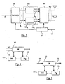
- FIG 7 illustrates in simplified form a receiving device comprising N R receiving antennas, according to this embodiment.
- This reception device comprises means for analyzing (71) the signal received, from an estimate of the transmission channel for example, means for determining (72) a distribution of the transmit antennas and specific efficiencies assigned to each group, and decoding means (73) of the packet transmitted.
- these determination means (72) jointly perform a selection of transmitting and / or receiving antennas, for deactivating certain transmitting and / or receiving antennas. More specifically, the subset of antennas active in transmission and / or reception is chosen from among all the possible combinations, so as to maximize for example the sum of the discrete capacity of the transmission system or the overall capacity (that is, say without taking into account the quantification of returns) of the system. Optimization is thus performed on all radio links.
- reception selection essentially makes it possible to reduce the complexity of the processing of the receiver.
- the adaptation information (such as the partitioning of the transmit antennas, the allocated powers, the efficiencies used in practice (less than or equal to those calculated) as well as the decoding order) are defined either in conjunction with the number of active antennas of the MIMO channel, ie once the number of active antennas determined.
- the correlated processing of these different information makes it possible in particular to reduce the quantization noise and thus to allow the increase of the performances in terms of spectral efficiency.
- the transmission power can in particular be predetermined and equidistributed between the different active transmit antennas.
- this adaptation information is then sent back to the transmitter in the form of a parameterization signal (CQI message).
- CQI message a parameterization signal
- the transmitter is then able to adapt to the optimal partition chosen, as well as the yields to be used for the transmission of a data packet.
- the decoding of the transmitted packet is implemented according to the decoding order chosen after the channel estimation and before transmission of the packet.
- figure 2 illustrates an exemplary structure of the parameterization signal 15.
- This signal comprises at least a first parameter field 1 , comprising information relating to a group distribution of the transmitting antennas, and a second parameter field 2 , comprising information relating to specific outputs assigned respectively to each of the groups of transmitting antennas.
- this parameterization signal 15 may also comprise a field 3 carrying information relating to specific powers allocated respectively to each of the transmitting antennas, or a field (not shown) carrying information relating to the active antennas of FIG. program.
- the figure 3 illustrates more precisely the operation on the transmission side. As illustrated on this figure 3 , the setting signal transmitted by the receiver is received by the transmitter of the multi-antenna system.
- the different fields of the signal of Parameters 15 are analyzed, so as to adapt the transmitter, by defining at least the distribution of transmit antennas by group and the yields associated with each group.
- the transmitter is in particular able to adapt to the partition for the moment of transmission t , as well as the returns per group.
- the control module 31 makes it possible to reconfigure a demultiplexer 32 into K outputs, and then to apply a space-time code module on each of these outputs.
- the control module 31 determines the transmit antennas applied to each group.
- the control module chooses for example ( N T 3 , N T 6 ) ⁇ 1 , (N T 1 , N T 2 ) ⁇ ⁇ 2 and ( N T 5 ) ⁇ ⁇ 3 , this distribution making it possible to optimize the performance of the multi-antenna system.
- the binary data stream at the input of the transmitter is first demultiplexed during a DEMUX stage 32, and converted into a number of independent streams K corresponding to the number of transmit antenna groups. defined in the parameterization signal 15 and extracted during the control step 31.
- the K streams are each separately encoded and mapped into an MCS modulation and modulation block 33 1 , ...., 33 K.
- the MCS blocks may be ST-MCS (Space-Time Modulation and Coding Scheme) type, for example space-time coding using ST-BICM type modulation. "Space Time Bit Interleaved Coded Modulation").
- the coding and modulation schemes 33 1 , .... 33 K controlled by the controller 31 taking into account the parameterization signal 15, thus make it possible to define specific efficiencies assigned respectively to each of the transmit antenna groups ⁇ 1 , ... ⁇ K. According to an alternative embodiment, these diagrams also make it possible to define specific powers allocated respectively to each of the transmitting antennas.
- coding and modulation blocks 33 1 ,..., 33 K are followed by a switch 34 (also called a demultiplexer) performing a bijection of all the data streams on all of the active antennas.
- a switch 34 also called a demultiplexer
- data decoding is performed per layer for each group ⁇ 1 ,..., ⁇ K of antennas.
- the first layer is detected vectorially (vector detector based for example on an MMSE criterion), and then decoded.
- the decoding order j may provide to decode the group ⁇ 1 during a first layer, and then to decode the group ⁇ K during a next layer.
- the signal After decoding a layer, the signal is re-encoded and then the interferences are regenerated and then subtracted from the received multiplexed signal. A vector successive interference suppression is thus performed.
- the maximum number of transmit antennas in a group must not exceed the number antennas active in reception. This constraint comes in particular from the whitening of the output of the MMSE vector detector.
- a first embodiment is considered below in which the determination of the adaptation information is performed after the selection of the active transmit antennas.
- ⁇ X 1 , ..., X M ⁇ be the set of partitions considered satisfying the following condition: ⁇ X , ⁇ ⁇ i ⁇ X where i ⁇ l K ⁇ we have ⁇ i ⁇ NOT R .
- C ⁇ i , j thus corresponds to the (continuous) efficiency obtained for the antenna group ⁇ t with respect to the decoding order j .
- R k i , j * ⁇ j is the yield chosen among the cardinality yields
- the metric M j , ⁇ is calculated from a metric F.
- This metric F is a function of the theoretical yields (which can take any value), conditioned by their capacity, itself a function of the power play ⁇ P 1 , ..., P N T allocated to each transmitting antenna and returns selected from those available.
- the choice of the returns is made by a minimization on both the power of emission and on the indices k allowing to choose the discrete yield closest to the theoretical one.
- the search for the minimum metric is thus carried out according to this embodiment on the set of permutations of the successive ordered decodings, on the set of power plays and on all the partitions to consider.
- the transmitter is informed of the chosen partition, and the choice of the yields to be used for each group of antennas belonging to the chosen partition.
- the decoding order does not need to be transmitted to the transmitter, since this information is only used at the receiver.
- the problem of the identification of the active antennas can be solved by widening the partition to the total number of antennas available on transmission, and by choosing a CQI associated with a null efficiency for the group comprising the inactive antennas.
- the metric F may take the form of a constrained Euclidean metric.
- Equation (8) is thus expressed more simply, since the minimization is carried out on each element of the partition with a permutation j fixed, whereas in the preceding situation (5) the minimization was carried out jointly on all the elements of the score.
- a second embodiment is considered hereinafter in which the determination of the adaptation information is performed together with the selection of the active transmission antennas.
- the selection of the active transmit antennas takes into account at least some adaptation information and vice versa.
- an algorithm for selecting active transmit antennas is described below, making it possible to jointly select a subset of n T transmission antennas from among the N T transmit antennas, a partition of transmission antennas. , an optimal decoding order, as well as optimized discrete yields (MCS) ( n T ⁇ N T ).
- the receiver performs, according to this second embodiment, during a step 82, a selection of the transmit antennas together with the choice of the partition, the decoding order, and the modulation and coding schemes.
- the receiver can know a MCS table to use (83), which it can use to build the parameterization signal.
- the setting signal is then transmitted to the transmitter (84).
- This joint processing can in particular be done in reception, in order to limit the number of CQI sent back to the transmitter, and thus to reduce the feedback.
- the selection of transmit antennas does not result in an increase in the amount of information in the return channel ("feedback" of the receiver), especially if the MCS of zero efficiency is included in the MCS table and if it is assumed that zero efficiency is assigned to the deactivated antennas.
- the MMSE-based receiver combined with successive interference subtraction with group efficiency control is optimal, assuming independent Gaussian inputs.
- the matrices A ⁇ i take a different form depending on the choice chosen for the receiver. Depending on the type of receiver considered, these matrices can be calculated thanks to the knowledge of the transmission channel in reception, or obtained by estimation on the pilot symbols.
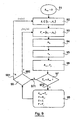
- the figure 9 presents an emission antenna selection algorithm, correlated to the adaptation of the yields.
- the antenna selection algorithm takes into account two inputs: information on the transmission channel (for example of the estimated transmission channel type), and a set of discrete output sets (table of MCS (possibly ST-MCS) to consider).
- variable R max corresponding to the maximum efficiency that can be achieved, is initialized to the value "0".
- the discretization of the flux capacity (that is to say the capacity for one of the groups of transmit antennas considered) on all (ST-) MCS available is realized in the selection algorithm thanks to the operator ⁇ ⁇ ⁇ (integer part), which makes it possible to choose the nearest MCS (or ST-MCS) by lower value.
- the power is considered fixed and, in the absence of transmission channel knowledge, equidistributed between all the active transmit antennas.
- each capacity per stream is conventionally calculated from matrix inversions, as in equation (14).
- B l + 1 B l - ⁇ d ⁇ B l ⁇ H ⁇ i + 1 I ⁇ i + 1 + ⁇ d ⁇ H ⁇ i + 1 ⁇ ⁇ B l ⁇ H ⁇ i + 1 - 1 ⁇ H ⁇ i + 1 ⁇ ⁇ B l
- the first algorithm described in relation to the figure 9 can be particularized and rewritten as a second algorithm.
- the first algorithm and the second algorithm (as well as those derived from it) can be simplified by searching only the optimal decoding order of the fixed partition.
- one of the embodiments relies on an iterative implementation starting from an empty set S.
- Another embodiment relies on an iterative implementation starting from a set S full, that is to say comprising the N T transmitting antennas. Indeed, the performance losses due to these iterative implementations are negligible.
- these two embodiments result in the same selection of the set S.
- the selected transmission antennas that is to say those chosen as activated, are added one by one to the set S.
- the transmission antenna selection algorithm relies on an iterative embodiment called “decremental”, that is to say starting with a set S of full transmit antennas including the N T antennas of emission, can be easily obtained from the previous incremental algorithm.
- the transmit antennas are subtracted one by one if the sum capacity of the set containing x antennas is greater than that containing x +1 antennas.
- the way of calculating the capabilities per antenna is performed in a manner similar to that described in relation to the first example, that is to say using a recursive method for obtaining the inverse matrices.
- a fixed decoding order is imposed by the way of adding the elements in the set S for an incremental type procedure.
- the decoding order is set during an initialization step. It may, for example, be based on a criterion for classifying the SINRs at the output of the MMSE before the suppression of interference; we test the suppression of the weakest at each iteration.
- An emission device comprises a memory 41 consisting of a buffer, a processing unit 42, equipped for example with a microprocessor ⁇ P, and driven by the computer program 43, implementing the transmission method according to the invention.
- the code instructions of the computer program 43 are for example loaded into a RAM memory before being executed by the processor of the processing unit 42.
- the processing unit 42 receives as input a stream binary data d , and a setting signal 15. for example in the form of a CQI message.
- the microprocessor of the processing unit 42 implements the steps of the transmission method described above, according to the instructions of the computer program 43, to adapt the distribution of the transmit antennas by group and assign specific yields to each one. groups, depending on the yields available in transmission, so as to optimize the transmission performance.
- the transmission device comprises means for receiving a parameterization signal transmitted by said receiver, means for selecting one of the distributions defined in the parameterization signal, means for distributing the transmitting antennas according to the groups of the selected distribution, and means for assigning to each of the groups the corresponding specific efficiency defined in the parameterization signal.
- the receiving device also comprises a memory 51, a processing unit 52, equipped for example with a microprocessor ⁇ P, and driven by the computer program 53, implementing the reception method according to the invention.
- the code instructions of the computer program 53 are for example loaded into a RAM before being executed by the processor of the processing unit 52.
- the processing unit 52 receives as input a signal received 11.
- the microprocessor of the processing unit 52 implements the steps of the reception method described above, according to the instructions of the computer program 53, to analyze the received signal and determine a signal parameterization device 15 defining at least one distribution of the antenna transmitting antenna groups (s) and specific efficiencies assigned respectively to each of the groups of antennas for each distribution, according to information representative of the transmission channel.
Description
Le domaine de l'invention est celui des communications numériques. Plus précisément, l'invention concerne l'émission et la réception de signaux dans le cadre de systèmes multi-antennes de type MIMO (de l'anglais « Multiple-Input Multiple-Output » pour « Entrées Multiples Sorties Multiples »).The field of the invention is that of digital communications. More specifically, the invention relates to the transmission and reception of signals in the context of multiple-input multiple-output (MIMO) type multi-antenna systems ("Multiple Multiple Input Multiple Output").
L'invention trouve notamment des applications dans le domaine des radiocommunications, dans des systèmes présentait des canaux de transmission sélectifs en fréquence (systèmes de type monoporteuse) ou non sélectifs en fréquence (systèmes de type multiporteuses).The invention finds particular applications in the field of radiocommunications, in systems has frequency selective transmission channels (single-carrier systems) or non-selective frequency (multi-carrier type systems).
En particulier, l'invention se situe au niveau de la couche physique de réseaux d'accès mobiles multi-antennes, et peut s'appliquer aux communications sur voie montante (d'un terminal vers une station de base), ainsi qu'aux communications sur voie descendante (d'une station de base vers un terminal).In particular, the invention is at the level of the physical layer of multi-antenna mobile access networks, and can be applied to uplink communications (from a terminal to a base station), as well as to downlink communications (from a base station to a terminal).
Les techniques d'émission/réception de signaux numériques dans des systèmes comprenant de multiples antennes présentent de nombreux avantages, notamment pour les réseaux d'accès mobiles. En effet, de telles techniques permettent une augmentation d'un débit de transmission, d'une capacité, ou encore d'une robustesse de ces systèmes multi-antennes, sans pour autant nécessiter une augmentation des puissances d'émission ou des bandes de fréquence allouées.The techniques for transmitting / receiving digital signals in systems comprising multiple antennas have many advantages, especially for mobile access networks. Indeed, such techniques allow an increase in a transmission rate, a capacity, or even a robustness of these multi-antenna systems, without requiring an increase in transmission power or frequency bands. allocated.
On connaît ainsi, selon l'art antérieur, une technique permettant d'atteindre la capacité en boucle ouverte pour des canaux à évanouissements non sélectifs en fréquence, sous l'hypothèse d'entrées gaussiennes indépendantes. Cette technique repose sur la mise en oeuvre d'un récepteur de type MMSE (de l'anglais « Minimum Mean-Square Error ») combiné à une annulation d'interférence successive, et sur la mise en oeuvre d'un contrôle de rendements par antenne, noté PARC (de l'anglais « Per Antenna Rate Control »), permettant d'adapter régulièrement le rendement de chaque antenne d'émission à la capacité du canal de transmission équivalent correspondant, et ainsi d'éviter une propagation d'erreurs au niveau de l'annulation d'interférences.Thus, according to the prior art, there is known a technique for achieving open-loop capacity for non-frequency selective fading channels, under the assumption of independent Gaussian inputs. This technique is based on the implementation of a receiver of the MMSE type (of the "Minimum Mean-Square Error") combined with a successive cancellation of interference, and on the implementation of a control of yields by antenna, noted PARC ("Per Antenna Rate Control"), allowing to regularly adjust the performance of each transmitting antenna to the capacity of the corresponding equivalent transmission channel, and thus to avoid a propagation of errors at the level of cancellation of interference.
On rappelle qu'on entend classiquement par « rendement » un choix de schéma de modulation et codage MCS (de l'anglais « Modulation and Coding Scheme »), c'est-à-dire qu'il comprend :
- le rendement du code de canal : par exemple 114, 113, 112, etc ;
- l'ordre de la modulation choisie : par exemple de type BPSK (en anglais « Binary Phase Shift Keying », en français « modulation de phase à 2 états »), QPSK (en anglais « Quadrature PSK », en français « modulation de phase en quadrature »), 16QAM (en anglais « 16-Quadrature Amplitude Modulations, en français « modulation d'amplitude en quadrature à 16 états »), etc.
- the performance of the channel code: for example 114, 113, 112, etc .;
- the order of the modulation chosen: for example BPSK type (in English "Binary Phase Shift Keying", in French "2-phase phase modulation"), QPSK (in English "Quadrature PSK", in French "phase modulation in quadrature "), 16QAM (in English" 16-Quadrature Amplitude Modulations, in English "quadrature amplitude modulation with 16 states"), etc.
En particulier, la technique notée SIC-PARC (pour «Successive Interference Cancellation - PARC ») permet de transmettre des flux de données indépendants, qui peuvent présenter des rendements différente, sur chacune des antennes d'émission d'un système multi-antennes. Selon cette technique, la puissance fournie à l'émission peut être uniformément distribuée entre toutes les antennes d'émission.In particular, the technique noted SIC-PARC (for "Successive Interference Cancellation - PARC") makes it possible to transmit independent data streams, which may have different yields, on each of the transmit antennas of a multi-antenna system. According to this technique, the power supplied to the transmission can be uniformly distributed between all the transmitting antennas.
En réception le rapport signal à bruit-plus-interférences SINR (de l'anglais « Signal-to-Interference-plus-Noise Ratio ») associé à chacune des antennes d'émission est déterminé, à partir d'une estimation du canal de transmission.In reception, the SINR signal-to-interference-plus-noise ratio associated with each of the transmit antennas is determined from an estimate of the transmission channel. transmission.
Ainsi, un récepteur connaissant une famille de schémas de modulation et codage disponible en émission peut déterminer les techniques de modulation et codage à utiliser en émission pour minimiser l'écart avec les performances théoriques, et transmettre ces éléments à l'émetteur grâce à une information issue du récepteur, encore appelée « feedback partiel instantané », ponte par exemple par un message CQI (de l'anglais « Channel Quality Indicator » pour « indicateur de qualité du canal »).Thus, a receiver knowing a family of modulation and coding schemes available for transmission can determine the modulation and coding techniques to be used in transmission in order to minimize the difference with the theoretical performances, and transmit these elements to the transmitter thanks to a piece of information. from the receiver, also called "instantaneous partial feedback", for example by spawning a CQI message ("Channel Quality Indicator" for "indicator quality of the channel ").
Plus précisément, encore, la norme d'émission considérée permet de définir une famille de schémas de modulation et codage MCS, et donc de rendements discrets, permettant à un récepteur de déterminer les MCS, et donc les rendements discrets par antenne, à utiliser.More precisely, again, the emission standard considered makes it possible to define a family of MCS modulation and coding schemes, and thus of discrete yields, enabling a receiver to determine the MCSs, and thus the discrete yields per antenna, to be used.
Une amélioration de cette technique de l'art antérieur, notée S-PARC, est notamment décrite dans le document
De cette manière, plutôt que considérer tous les flux associés à chaque antenne d'émission de manière indépendante, on considère uniquement les flux associés aux antennes d'émission actives. Ainsi, le nombre de flux indépendant transmis, égal au nombre d'antennes actives, est inférieur ou égal au nombre total d'antennes d'émissionIn this way, rather than considering all the streams associated with each transmitting antenna independently, only the streams associated with the active transmit antennas are considered. Thus, the number of independent streams transmitted, equal to the number of active antennas, is less than or equal to the total number of transmitting antennas
La sélection des antennes d'émission peut être effectuée en fonction de la qualité du canal de transmission et/ou de la corrélation des antennes d'émission, de façon à maximiser notamment la somme des rendements sur tous les flux, et donc la capacité globale du système.The selection of the transmit antennas can be done according to the quality of the transmission channel and / or the correlation of the transmit antennas, so as to maximize in particular the sum of the returns on all the streams, and therefore the overall capacity. of the system.
Autrement dit, l'attribution des rendements discrets à chaque antenne d'émission est basée sur la réception d'un CQI par antenne, indiquant le rendement discret par antenne (MCS) à utiliser.In other words, the allocation of the discrete returns to each transmitting antenna is based on the reception of an CQI per antenna, indicating the discrete output per antenna (MCS) to be used.
Ainsi, comme illustré en
Cependant, un inconvénient de cette technique est qu'elle ne prend pas en compte le jeu de rendements discrets disponible à l'émission lors de la sélection des antennes actives. En pratique, cette technique souffre donc d'un bruit de quantification dû à la famille de rendements discrets disponibles. Par conséquent, la discrétisation des rendements théoriques appliquée par la suite (c'est-à-dire le choix du schéma de modulation et codage MCS à utiliser pour minimiser l'écart avec le rendement théorique, parmi les MCS disponibles) provoque une perte d'efficacité spectrale.However, a disadvantage of this technique is that it does not take into account the set of discrete yields available on transmission when selecting active antennas. In practice, this technique therefore suffers from a quantization noise due to the family of discrete yields available. Therefore, the discretization of the theoretical yields subsequently applied (ie the choice of modulation scheme and MCS coding to be used to minimize the difference with the theoretical yield, among the MCS available) causes a loss of spectral efficiency.
Selon une autre technique, on cherche à optimiser les puissances et les rendements alloués. Par exemple,
Cette technique utilise également un codage de type scalaire, indépendant par antenne, choisi de façon à approcher une capacité maximale définie par la limite de Shannon, notamment en vue d'obtenir un taux d'erreur binaire faible et ainsi maximiser la capacité globale du système.This technique also uses an antenna-independent scalar type coding chosen to approach a maximum capacity defined by the Shannon limit, in particular in order to obtain a low bit error rate and thus maximize the overall capacity of the system. .
Cependant, un inconvénient de cette technique d'optitnisation conjointe des rendements et des puissances, associée à la recherche d'un ordre de décodage optimal pour s'adapter à la distribution discrète des rendements disponibles, est qu'elle ne fonctionne que dans le cadre d'un codage scalaire.However, a disadvantage of this technique of joint optitnisation yields and powers, associated with the search for an optimal decoding order to adapt to the discrete distribution of available yields, is that it only works in the context a scalar encoding.
On constate en effet que les techniques de l'art antérieur traitent toujours chaque antenne d'émission séparément (codage scalaire), un exemple est le document
L'invention propose une solution nouvelle qui ne présente pas l'ensemble de ces inconvénients de l'art antérieur, sous la forme d'un procédé de réception d'un signal reçu, correspondant à un signal de données émis par un émetteur à destination d'un récepteur via un canal de transmission, ledit émetteur comprenant NT antennes d'émission et ledit récepteur comprenant NR antennes de réception, avec NT et NR supérieurs ou égaux à 2.The invention proposes a new solution that does not have all of these disadvantages of the prior art, in the form of a method of receiving a received signal, corresponding to a data signal transmitted by a transmitter to a destination. a receiver via a transmission channel, said transmitter comprising N T transmitting antennas and said receiver comprising N R receiving antennas, with N T and N R greater than or equal to 2.
Selon l'invention, un tel procédé de réception comprend les étapes suivantes :
- analyse dudit signal reçu, délivrant une information représentative dudit canal de transmission;
- détermination périodique et/ou en fonction d'une variation dudit canal de transmission :
- ■ d'au moins une répartition desdites antennes d'émission en au moins un groupe d'au moins une antenne, en fonction de ladite information représentative du canal de transmission, au moins un groupe comprenant au moins deux antennes d'émission pour au moins une desdites déterminations ;
- ■ des rendements spécifiques affectés respectivement à chacun desdits groupes d'antennes, pour chaque répartition en fonction de ladite information représentative du canal de transmission ;
- transmission audit émetteur d'un signal de paramétrage définissant la ou lesdites répartitions et lesdits rendements spécifiques.
- analyzing said received signal, delivering information representative of said transmission channel;
- periodic determination and / or as a function of a variation of said transmission channel:
- At least one distribution of said transmission antennas in at least one group of at least one antenna, as a function of said information representative of the transmission channel, at least one group comprising at least two transmitting antennas for at least one of said determinations;
- Specific yields respectively assigned to each of said groups of antennas, for each distribution according to said information representative of the transmission channel;
- transmitting to said transmitter a parameterizing signal defining said distribution (s) and said specific yields.
Ainsi, l'invention propose une technique permettant d'adapter une répartition par groupe des antennes d'émission, en fonction d'une information représentative du canal de transmission, de façon à optimiser les performances de transmission en fonction notamment des rendements de code disponibles en émission. On considère ainsi un partitionnement des antennes en émission, c'est-à-dire des groupes disjoints d'antennes d'émission, un groupe comprenant au moins une antenne d'émission.Thus, the invention proposes a technique making it possible to adapt a group distribution of the transmission antennas, as a function of information representative of the transmission channel, so as to optimize the transmission performance as a function, in particular, of the available code efficiencies. in program. It is thus considered a partitioning antennas in transmission, that is to say disjoint groups of transmit antennas, a group comprising at least one transmitting antenna.
Le procédé de réception selon l'invention permet donc de transmettre à l'émetteur un signal de paramétrage définissant des informations d'adaptation, comprenant au moins une répartition en groupes et les rendements alloués à chaque groupe selon les différentes répartitions, pour choisir les valeurs adéquates de ces paramètres de façon à optimiser le débit (la capacité), et/ou la robustesse, etc, du système multi-antennes. Ce signal de paramétrage est par exemple transmis du récepteur vers l'émetteur (« feedback » du récepteur) au moyen d'un message CQI.The reception method according to the invention therefore makes it possible to transmit to the transmitter a parameterization signal defining adaptation information, comprising at least a distribution in groups and the yields allocated to each group according to the different distributions, for choosing the values. these parameters in order to optimize the throughput (capacity), and / or robustness, etc., of the multi-antenna system. This setting signal is for example transmitted from the receiver to the transmitter ("feedback" of the receiver) by means of a CQI message.
Par exemple, si plusieurs répartitions envisageables sont définies dans le signal de paramétrage, c'est l'émetteur qui sélectionnera la répartition la mieux adaptée, réception de ce signal de paramétrage.For example, if several possible distributions are defined in the parameterization signal, it is the transmitter which will select the most suitable distribution, reception of this parameterization signal.
En revanche, si une unique répartition est définie dans le signal de paramétrage, cette répartition des antennes d'émission sera imposée à l'émetteur.On the other hand, if a single distribution is defined in the parameterization signal, this distribution of the transmit antennas will be imposed on the transmitter.
On remarque qu'un changement dans la répartition des antennes d'émission peut modifier les valeurs de capacité du canal de transmission, obtenues pour chaque groupe, et ainsi, nécessiter de modifier certaines valeurs de rendements attribuées en émission de manière à optimiser les performances de transmission, tout en respectant les rendements discrets disponibles à l'émission.It should be noted that a change in the distribution of the transmit antennas can modify the transmission channel capacity values obtained for each group, and thus require the modification of certain transmit performance values in order to optimize the performance of the transmission antennas. transmission, while respecting the discreet returns available on the program.
On considère bien entendu que les groupes d'antennes peuvent être de cardinalité distincte, c'est-à-dire que les différents groupes d'antennes ne comprennent pas nécessairement le même nombre d'antennes d'émission.Of course, the antenna groups can be of distinct cardinality, that is, the different antenna groups do not necessarily include the same number of transmitting antennas.
On considère également que le nombre maximal d'antennes d'émission dans un groupe ne doit pas dépasser le nombre d'antennes en réception. Ainsi, le nombre d'antennes d'émission dans un groupe est compris entre 1 et NR.It is also considered that the maximum number of transmit antennas in a group should not exceed the number of receiving antennas. Thus, the number of transmitting antennas in a group is between 1 and N R.
Ainsi, l'invention propose un système prenant en compte l'existence d'une limitation du nombre de rendements de code disponibles à l'émetteur (fixé par la norme d'émission considérée) qui vise à réduire le bruit de quantification.Thus, the invention proposes a system that takes into account the existence of a limitation on the number of code efficiencies available to the transmitter (set by the transmission standard under consideration) which aims to reduce the quantization noise.
En particulier, les étapes d'analyse et de transmission sont également mises en oeuvre de façon périodique et/ou en fonction d'une variation significative dudit canal de transmission, c'est-à-dire une variation supérieure à un seuil prédéterminé.In particular, the analysis and transmission steps are also implemented periodically and / or as a function of a significant variation of said transmission channel, that is to say a variation greater than a predetermined threshold.
Ces étapes d'analyse et de transmission peuvent également être mises en oeuvre en fonction d'une requête d'un utilisateur, ou encore d'une requête de l'émetteur.These analysis and transmission steps can also be implemented according to a request from a user, or a request from the issuer.
On adapte ainsi la répartition par groupes des antennes d'émission et les rendements attribués à chaque groupe d'antennes de façon à exploiter de manière optimale le système multi-antennes.The grouping of the transmitting antennas and the yields attributed to each group of antennas are thus adapted to optimally exploit the multi-antenna system.
Selon une caractéristique particulière de l'invention, ladite étape de détermination détermine des puissances spécifiques allouées respectivement à chacune desdites antennes d'émission, et ledit signal de paramétrage définit également ces puissances.According to a particular characteristic of the invention, said determining step determines specific powers allocated respectively to each of said transmitting antennas, and said setting signal also defines these powers.
On adapte ainsi différentes informations d'adaptation, encore appelées paramètres, en fonction d'une information représentative du canal de transmission, et notamment de la qualité de ce canal, de façon à optimiser les performances du système multi-antennes.Different adaptation information, also called parameters, is thus adapted according to information representative of the transmission channel, and in particular the quality of this channel, so as to optimize the performance of the multi-antenna system.
Selon un mode de réalisation particulier, le procédé de réception comprend une étape de sélection d'antennes d'émission parmi lesdites NT antennes d'émission, dites antennes actives, au moins en fonction de ladite information représentative du canal de transmission. Ledit signal de paramétrage définit alors également les antennes actives, c'est-à-dire comprend une information permettant d'identifier les antennes sélectionnées.According to a particular embodiment, the reception method comprises a step of selecting transmission antennas among said N T transmit antennas, said active antennas, at least as a function of said representative information of the transmission channel. Said parametric signal then also defines the active antennas, that is to say includes information to identify the selected antennas.
Plus précisément, cette étape de sélection d'antennes peut conduire à la désactivation des antennes d'émission non sélectionnées. On balaye ainsi, selon ce mode de réalisation, chaque antenne d'émission du système multi-antennes, et on désactive les antennes présentant par exemple une corrélation trop importante, ou étant associées à un canal de transmission fortement bruité, etc. Cette activation/désactivation des antennes d'émission est notamment mise en oeuvre de manière à optimiser la capacité du système multi-antennes.More precisely, this antenna selection step can lead to the deactivation of the unselected transmission antennas. Thus, according to this embodiment, each transmission antenna of the multi-antenna system is scanned, and the antennas are deactivated, for example having too much correlation, or being associated with a highly noisy transmission channel, etc. This activation / deactivation of the transmit antennas is in particular implemented by to optimize the capacity of the multi-antenna system.
Par exemple, le signal de paramétrage peut définir un groupe comprenant l'ensemble des antennes d'émission désactivées, et définir un rendement nul affecté à ce groupe d'antennes d'émission.For example, the parameterization signal may define a group comprising all the deactivated transmit antennas, and define a null efficiency assigned to this group of transmit antennas.
En particulier, suivant un tirage de canal particulier, l'algorithme de sélection d'antennes peut suggérer d'utiliser toutes les antennes d'émission à disposition, c'est-à-dire les NT antennes d'émission.In particular, according to a particular channel draw, the antenna selection algorithm may suggest using all available transmit antennas, i.e. N T transmit antennas.
Selon un aspect particulier de l'invention, l'étape de sélection est mise en oeuvre conjointement avec ladite étape de détermination.According to one particular aspect of the invention, the selection step is carried out jointly with said determination step.
En d'autres termes, l'étape de sélection des antennes actives d'émission tient compte d'au moins certaines informations d'adaptation et vice-versa.In other words, the step of selecting the active transmit antennas takes into account at least some adaptation information and vice versa.
En effet, l'optimisation conjointe de la sélection d'antennes et de l'adaptation des rendements permet notamment d'éviter une dégradation importante de la capacité globale du système multi-antennes, due à la discrétisation des rendements à l'émission.Indeed, the joint optimization of the selection of antennas and the adaptation of the yields makes it possible in particular to avoid a significant degradation of the overall capacity of the multi-antenna system, due to the discretization of the emission efficiencies.
Par exemple, une répartition ordonnée optimisée Γ*, les rendements spécifiques par groupe R* pour cette répartition, et un ensemble optimisé S* des antennes actives, peuvent être déterminés à partir des équations suivantes : ![]()
![]()
avec : 
![]()
![]()
où:
- H est représentatif dudit canal de transmission :
- ρ corresponds au rapport signal à bruit ;
- {P 1,···, PNT } correspond à un jeu de puissances d'émission attribuées à chaque antenne d'émission :
- J |Δ| correspond à un jeu de rendements discrets disponibles à l'émission ;
- Δ correspond à un groupe inclus dans la répartitions Γ ;
- A Δ est une matrice représentative dudit récepteur.
with:
or:
- H is representative of said transmission channel:
- ρ corresponds to the signal-to-noise ratio;
- { P 1 , ···, P NT } corresponds to a set of transmission powers allocated to each transmitting antenna:
- J | Δ | is a game of discrete returns available on the show;
- Δ corresponds to a group included in the distributions Γ;
- A Δ is a representative matrix of said receiver.
Selon un aspect particulier de l'invention, ladite répartition est déterminée en tenant compte d'au moins un des éléments appartenant au groupe comprenant :
- des rendements discrets disponibles à l'émission;
- des puissances associées à chaque répartition en groupes desdites antennes d'émission ;
- un ordre de décodage mis en oeuvre au niveau dudit récepteur ;
- le nombre NR d'antennes de réception ;
- un nombre d'antennes d'émission actives.
- discrete returns available on issue;
- powers associated with each division into groups of said transmitting antennas;
- a decoding command implemented at said receiver;
- the number N R of receiving antennas;
- a number of active transmit antennas.
Ainsi, la répartition par groupes des antennes d'émission est adaptée en cours de transmission, par exemple pour mieux suivre les variations du canal de transmission.Thus, the grouping of transmit antennas is adapted during transmission, for example to better monitor the variations of the transmission channel.
En particulier, lors du choix du partitionnement des antennes en émission, il est possible que plusieurs partitions atteignent la capacité maximale du système. La partition optimale est alors choisie de façon à respecter des contraintes matérielles primordiales, telles qu'une complexité de décodage faible, un « feedback » minimal entre le récepteur et l'émetteur, etc.In particular, when choosing the partitioning of transmitting antennas, it is possible for several partitions to reach the maximum capacity of the system. The optimal partition is then chosen so as to respect essential hardware constraints, such as a low decoding complexity, a minimum "feedback" between the receiver and the transmitter, and so on.
En particulier, le procédé de réception selon un des modes de réalisation de l'invention met en oeuvre une étape de détermination d'un ordonnancement desdits groupes, et une étape de décodage mise en oeuvre successivement pour chaque groupe suivant ledit ordonnancement.In particular, the reception method according to one of the embodiments of the invention implements a step of determining an order of said groups, and a decoding step implemented successively for each group following said scheduling.
On joue ainsi sur les degrés de liberté disponibles, par exemple l'ordre de décodage des différents groupes, la façon de partitionner les antennes d'émission par groupes et la distribution des rendements en émission, en tenant compte des schémas de modulation et codage disponibles à l'émission définis par la norme considérée, de façon à réduire l'écart entre les rendements théoriques et les rendements disponibles.Thus, we play on the degrees of freedom available, for example the order of decoding of the different groups, the way of partitioning the transmit antennas in groups and the distribution of the transmission yields, taking into account the modulation and coding schemes available. at issuance defined by the standard considered, in order to reduce the gap between the theoretical yields and the available returns.
En particulier, un changement dans la répartition par groupes des antennes d'émission nécessite une modification de l'ordonnancement.In particular, a change in the grouping of transmit antennas requires a modification of the scheduling.
Notamment, ledit ordonnancement minimise une métrique tenant compte des répartitions en groupes desdites antennes d'émission et/ou des puissances fournies par lesdites antennes d'émission et/ou des rendements spécifiques et/ou d'un ordre de décodage.In particular, said scheduling minimizes a metric taking into account the group distributions of said transmit antennas and / or the powers provided by said transmit antennas and / or specific yields and / or a decoding order.
Un autre aspect de l'invention concerne un procédé d'émission d'un signal de données d'un émetteur vers un récepteur via un canal de transmission, ledit émetteur comprenant NT antennes d'émission et ledit récepteur comprenant NR antennes de réception, avec NT et NR supérieurs ou égaux à 2.Another aspect of the invention relates to a method of transmitting a data signal from a transmitter to a receiver via a transmission channel, said transmitter comprising N T transmit antennas and said receiver comprising N R receiving antennas with N T and N R greater than or equal to 2.
Selon l'invention, un tel procédé d'émission comprend les étapes suivantes :
- réception d'un signal de paramétrage transmis par ledit récepteur définissant :
- ■ au moins une répartitions desdites antennes d'émission en au moins un groupe d'au moins une antenne ;
- ■ des rendements spécifiques affectés respectivement à chacun desdits groupes d'antennes, pour chaque répartition,
obtenus, en fonction d'une information représentative du canal de transmission, par détermination périodique et/ou fonction d'une variation du canal de transmission,
au moins un groupe comprenant au moins deux antennes d'émission pour au moins une détermination ;
- sélection d'une desdites répartitions parmi la ou lesdites répartitions définies dans ledit signal de paramétrage ;
- répartition desdites antennes d'émission selon les groupes de ladite répartition sélectionnée ;
- attribution à chacun desdits groupes du rendement spécifique correspondant, défini dans ledit signal de paramétrage.
- receiving a parameterization signal transmitted by said receiver defining:
- At least one distribution of said transmitting antennas in at least one group of at least one antenna;
- Specific yields assigned respectively to each of said groups of antennas, for each distribution,
obtained, according to information representative of the transmission channel, by periodic determination and / or function of a variation of the transmission channel,
at least one group comprising at least two transmitting antennas for at least one determination;
- selecting one of said distributions from said one or more distributions defined in said parameterization signal;
- distribution of said transmitting antennas according to the groups of said selected distribution;
- allocation to each of those groups of the specific yield corresponding, defined in said parameterization signal.
Un tel procédé d'émission est notamment adapté à recevoir un signal de paramétrage émis par exemple selon le procédé de réception décrit ci-dessus.Such a transmission method is in particular adapted to receive a parameterization signal transmitted for example according to the reception method described above.
Ainsi, ce procédé d'émission est adaptatif et contrôlé par un « feedback » (retour) du récepteur, par exemple lors de la mise à jour des paramètres définis dans le signal de paramétrage.Thus, this transmission method is adaptive and controlled by a "feedback" of the receiver, for example when updating the parameters defined in the parameterization signal.
Dans un autre mode de réalisation, l' invention concerne un dispositif de réception d'un signal reçu, correspondant à un signal de données émis par un émetteur via un canal de transmission, ledit émetteur comprenant NT antennes d'émission et ledit dispositif de réception comprenant NR antennes de réception, avec NT et NR supérieurs ou égaux à 2.In another embodiment, the invention relates to a device for receiving a received signal, corresponding to a data signal transmitted by a transmitter via a transmission channel, said transmitter comprising N T transmit antennas and said transmission device. receiving comprising N R receiving antennas, with N T and N R greater than or equal to 2.
Selon l'invention, un tel dispositif de réception comprend:
- des moyens d'analyse dudit signal reçu, délivrant une information représentative dudit canal de transmission ;
- des moyens de détermination périodique et/ou en fonction d'une variation dudit canal de transmission :
- ■ d'au moins une répartition desdites antennes d'émission en au moins un groupe d'au moins une antenne, en fonction de ladite information représentative du canal de transmission, au moins un groupe comprenant au moins deux antennes d'émission pour au moins une desdites déterminations;
- ■ des rendements spécifiques affectés respectivement à chacun desdits groupes d'antennes, pour chaque répartition en fonction de ladite information représentative du canal de transmission ;
- des moyens de transmission audit émetteur d'un signal de paramétrage définissant la ou lesdites répartitions et lesdits rendements spécifiques. Un tel dispositif de réception est notamment adapté à mettre en oeuvre le procédé de réception décrit précédemment. Il s'agit par exemple d'une station de base, ou d'un terminal de type radiotéléphone, ordinateur portable, assistant personnel de type PDA (en anglais « Personal Digital Assistant »), selon que l'on soit en lien montant ou descendant.
- means for analyzing said received signal, delivering information representative of said transmission channel;
- means for periodic determination and / or as a function of a variation of said transmission channel:
- At least one distribution of said transmission antennas in at least one group of at least one antenna, as a function of said information representative of the transmission channel, at least one group comprising at least two transmitting antennas for at least one of said determinations;
- Specific yields respectively assigned to each of said groups of antennas, for each distribution according to said information representative of the transmission channel;
- means for transmitting to said transmitter a parameterizing signal defining said distribution (s) and said specific efficiencies. Such a reception device is particularly suitable for implementing the reception method described above. This is for example a base station, or a terminal type radiotelephone, laptop, assistant Personal PDA type (in English "Personal Digital Assistant"), depending on whether one is in ascending or descending link.
Un autre aspect de l'invention concerne un dispositif d'émission d'un signal de données vers un récepteur via un canal de transmission, ledit dispositif d'émission comprenant NT antennes d'émission et ledit récepteur comprenant NR antennes de réception, avec NT et NR supérieurs ou égaux à 2.Another aspect of the invention relates to a device for transmitting a data signal to a receiver via a transmission channel, said transmission device comprising N T transmitting antennas and said receiver comprising N R receiving antennas, with N T and N R greater than or equal to 2.
Selon l'invention, un tel dispositif d'émission comprend :
- des moyens de réception d'un signal de paramétrage (15) transmis par ledit récepteur définissant :
- ■ au moins une répartition desdites antennes d'émission en au moins un groupe d'au moins une antenne ;
- ■ des rendements spécifiques affectés respectivement à chacun desdits groupes d'antennes, pour chaque répartition ;
obtenus, en fonction d'une information représentative du canal de transmission, par détermination périodique et/ou fonction d'une variation du canal de transmission,
au moins un groupe comprenant au moins deux antennes d'émission pour au moins une détermination ;
- des moyens de sélection d'une desdites répartitions parmi la ou lesdites répartitions définies dans ledit signal de paramétrage ;
- des moyens de répartition desdites antennes d'émission selon les groupes de ladite répartition sélectionnée ;
- des moyens d'attribution à chacun desdits groupes du rendement spécifique correspondant, défini dans ledit signal de paramétrage.
- means for receiving a parameterization signal (15) transmitted by said receiver defining:
- At least one distribution of said transmitting antennas in at least one group of at least one antenna;
- Specific yields assigned respectively to each of said groups of antennas, for each distribution;
obtained, according to information representative of the transmission channel, by periodic determination and / or function of a variation of the transmission channel,
at least one group comprising at least two transmitting antennas for at least one determination;
- means for selecting one of said distributions from said one or more distributions defined in said parameterization signal;
- means for distributing said transmitting antennas according to the groups of said selected distribution;
- means for assigning to each of said groups the corresponding specific efficiency defined in said parameterization signal.
Un tel dispositif d'émission est notamment adapté à mettre en oeuvre le procédé d'émission décrit précédemment. Il s'agit par exemple d'une station de base, ou d'un terminal de type radiotéléphone, ordinateur portable, assistant personnel de type PDA (en anglais « Personal Digital Assistant »), selon que l'on soit en lien montant ou descendant.Such an emission device is particularly suitable for implementing the transmission method described above. This is for example a base station, or a terminal type radiotelephone, laptop, personal assistant type PDA (in English "Personal Digital Assistant"), depending on whether one is link up or descending.
Encore un autre mode de réalisation de l'invention concerne un produit programme d'ordinateur téléchargeable depuis un réseau de communication et/ou enregistré sur un support lisible par ordinateur et/ou exécutable par un processeur, comprenant des instructions de code de programme pour la mise en oeuvre du procédé de réception décrit ci/dessus, et/ou un produit programme d'ordinateur téléchargeable depuis un réseau de communication et/ou enregistré sur un support lisible par ordinateur et/ou exécutable par un processeur, comprenant des instructions de code de programme pour la mise en oeuvre du procédé d'émission décrit ci-dessus.Yet another embodiment of the invention relates to a computer program product downloadable from a communication network and / or recorded on a computer readable medium and / or executable by a processor, including program code instructions for the implementation of the reception method described above, and / or a computer program product downloadable from a communication network and / or recorded on a computer-readable and / or executable medium by a processor, comprising code instructions program for carrying out the transmission method described above.
Finalement, un autre aspect de l'invention concerne un signal de paramétrage d'un émetteur, transmis d'un récepteur à destination dudit émetteur via un canal de transmission, ledit émetteur comprenant NT antennes d'émission et ledit récepteur comprenant NR antennes de réception, avec NT et NR supérieurs ou égaux à 2.Finally, another aspect of the invention relates to a parameterizing signal of a transmitter, transmitted from a receiver to said transmitter via a transmission channel, said transmitter comprising N T transmitting antennas and said receiver comprising N R antennas with N T and N R greater than or equal to 2.
Selon l'invention, un tel signal de paramétrage comprend au moins un champ de paramétrage comprenant :
- une information relative à au moins une répartition desdites antennes d'émission en au moins un groupe d'au moins une antenne ; et
- une information relative à des rendements spécifiques affectés respectivement à chacun desdits groupes d'antennes, pour chaque répartition,
au moins un groupe comprenant au moins deux antennes d'émission pour au moins une détermination.According to the invention, such a parameterization signal comprises at least one parameter field comprising:
- information relating to at least one distribution of said transmitting antennas in at least one group of at least one antenna; and
- information relating to specific yields assigned respectively to each of said groups of antennas, for each distribution,
at least one group comprising at least two transmitting antennas for at least one determination.
Un tel signal de paramétrage peut notamment définir, selon le procédé de réception décrit précédemment, différents paramètres ou informations d'adaptation mis en oeuvre en émission, comme la répartition des antennes d'émission par groupes, les rendements attribués à chacun des groupes, les antennes sélectionnées (antennes actives), les puissances attribuées à chaque antenne d'émission, ...Such a parameterization signal can in particular define, according to the reception method described above, various parameters or adaptation information implemented in transmission, such as the distribution of the transmit antennas in groups, the yields attributed to each of the groups, the selected antennas (active antennas), the powers allocated to each transmitting antenna, ...
Ce signal de paramétrage pourra bien sûr comporter les différentes caractéristiques relatives au procédé de réception selon l'invention.This parameterization signal may of course include the various characteristics relating to the reception method according to the invention.
D'autres caractéristiques et avantages de l'invention apparaîtront plus clairement à la lecture de la description suivante d'un mode de réalisation particulier, donné à titre de simple exemple illustratif et non limitatif, et des dessins annexés, parmi lesquels :
- la
figure 1 illustre les principales étapes du procédé de réception selon l'invention; - la
figure 2 présente un exemple de structure de signal de paramétrage : - la
figure 3 illustre un exemple de dispositif d'émission dans un système de transmission multi-antennes selon l'invention ; - les
figures 4 et 5 présentent respectivement la structure d'un dispositif d'émission et d'un dispositif de réception selon un mode de réalisation particulier de l'invention ; - la
figure 6 illustre les principales étapes de la technique S-PARC, décrite en relation avec l'art antérieur ; - la
figure 7 propose un exemple de dispositif de réception dans un système de transmission multi-antennes selon l'invention ; - la
figure 8 illustre les principales étapes de la sélection d'antennes actives d'émission conjointement à la détermination des informations d'adaptation ; et - la
figure 9 propose un algorithme pour la sélection des antennes actives.
- the
figure 1 illustrates the main steps of the reception method according to the invention; - the
figure 2 shows an example of a parameterization signal structure: - the
figure 3 illustrates an exemplary transmission device in a multi-antenna transmission system according to the invention; - the
Figures 4 and 5 respectively show the structure of a transmitting device and a receiving device according to a particular embodiment of the invention; - the
figure 6 illustrates the main steps of the S-PARC technique, described in connection with the prior art; - the
figure 7 proposes an example of reception device in a multi-antenna transmission system according to the invention; - the
figure 8 illustrates the main steps of the selection of active transmit antennas together with the determination of the adaptation information; and - the
figure 9 proposes an algorithm for the selection of active antennas.
Le principe général de l'invention repose sur la transmission, d'un récepteur à un émetteur dans un système MIMO comprenant au moins deux antennes d'émission et au moins deux antennes de réception, d'un signal de paramétrage permettant de définir des informations d'adaptation, côté émission, comprenant au moins :
- au moins une répartition en un ou plusieurs groupes des antennes d'émission, et
- des rendements spécifiques attribués à chacun des groupes d'antennes d'émission, pour chaque répartition.
- at least one distribution in one or more groups of the transmitting antennas, and
- specific yields attributed to each of the transmit antenna groups, for each distribution.
On considère ainsi une répartition adaptative des antennes d'émission, c'est-à-dire que d'une remontée d'information du récepteur vers l'émetteur à une autre (« feedback » du récepteur), le choix de la partition peut différer, permettant ainsi de s'adapter aux variations du canal de transmission.An adaptive distribution of the transmitting antennas is thus considered, that is to say that a feedback from the receiver to the transmitter to another ("feedback" receiver), the choice of partition can differ, thus making it possible to adapt to variations in the transmission channel.
En particulier, le « feedback » du récepteur peut soit comprendre une unique répartition en groupes, et imposer ainsi son choix à l'émetteur, soit comprendre plusieurs répartitions envisageables, et laisser alors à l'émetteur le choix de la répartition optimisée parmi ces répartitions envisageables.In particular, the "feedback" of the receiver can either comprise a single distribution in groups, and thus impose its choice on the transmitter, or include several possible distributions, and then leave the issuer the choice of optimized distribution among these distributions conceivable.
Ainsi, l'intérêt de grouper les antennes d'émission selon ce mode de réalisation particulier de l'invention réside dans une meilleure adaptation des rendements disponibles compte tenu d'un choix optimisé de répartition.Thus, the advantage of grouping the transmit antennas according to this particular embodiment of the invention lies in a better adaptation of the available yields given an optimized choice of distribution.
De plus, selon une variante de réalisation décrite par la suite, le signal de paramétrage peut également définir les puissances allouées par antenne, ce qui permet une meilleure adaptation aux rendements disponibles.In addition, according to an alternative embodiment described below, the parameterization signal can also define the powers allocated per antenna, which allows a better adaptation to the available yields.
La modification des puissances d'émission implique par la suite l'obtention de nouvelles valeurs de capacités pour chaque groupe d'antennes, ce qui peut nécessiter une modification de l'ordonnancement (encore appelé ordre de décodage) choisi de façon à conserver un système multi-antennes optimisé.The modification of the transmission powers then implies obtaining new capacity values for each group of antennas, which may require a modification of the scheduling (also called decoding order) chosen so as to maintain a system multi-antenna optimized.
Par principe, il faut veiller à ce que la distribution de puissance par antenne d'émission ne dégrade pas trop la capacité du système multi-antennes. Par conséquent, il est souhaitable de définir une plage maximale de variations autour d'une valeur moyenne de puissance associée à chaque antenne d'émission et un pas de quantification.In principle, care must be taken that the transmit antenna power distribution does not degrade the capacity of the multi-antenna system too much. Therefore, it is desirable to define a maximum range of variation around an average power value associated with each transmit antenna and a quantization step.
Selon une autre variante, le signal de paramétrage peut également définir les antennes actives et celles non actives.According to another variant, the parameterization signal can also define active and non-active antennas.
Selon encore une autre variante, on se place dans un contexte de feedback réduit, en ne considérant pas l'adaptation des puissances d'émission. On considère ainsi une puissance prédéterminée, et équidistribuée entre les différentes antennes d'émission (actives), en l'absence de connaissance du canal en émission.According to yet another variant, one places oneself in a context of reduced feedback, while not considering the adaptation of the transmission powers. Thus, a predetermined power is considered, and equidistributed between the different transmit antennas (active), in the absence of knowledge of the transmission channel.
On s'attache ci-après à décrire plus précisément un mode de réalisation particulier de l'invention, selon lequel un signal de données est transmis d'un émetteur comprenant NT antennes d'émission vers un récepteur comprenant NR antennes de réception via un canal de transmission, avec NT supérieur ou égal à 2 et NR supérieur ou égal à 2.A particular embodiment of the invention will be described below, according to which a data signal is transmitted from a transmitter comprising N T transmit antennas to a receiver comprising N R receiving antennas via a transmission channel, with N T greater than or equal to 2 and N R greater than or equal to 2.
Plus précisément, selon ce mode de réalisation particulier, le récepteur détermine une unique répartition par groupes des antennes d'émission, et des rendements spécifiques affectés à chaque groupe, en fonction d'une information représentative du canal de transmission (par exemple une estimation du canal de propagation ou des rapports SNR (signal à bruit)), et transmet ces informations d'adaptation à l'émetteur au moyen du signal de paramétrage.More specifically, according to this particular embodiment, the receiver determines a single distribution by groups of transmit antennas, and specific yields assigned to each group, according to information representative of the transmission channel (for example an estimate of the transmission channel). propagation channel or SNR (signal to noise) reports), and transmits this adaptation information to the transmitter by means of the parameterization signal.
On considère notamment que selon ce mode de réalisation de l'invention, le nombre maximal d'antennes d'émission dans un groupe ne doit pas dépasser le nombre d'antennes actives en réception. Cette contrainte provient notamment du blanchiment spatial de la sortie du détecteur vectoriel MMSE.In particular, it is considered that according to this embodiment of the invention, the maximum number of transmitting antennas in a group must not exceed the number of antennas active in reception. This constraint comes in particular from the whitening of the output of the MMSE vector detector.
Plus précisément, on considère un « rendement» correspondant à un choix de modulation et codage espace-temps (ST-MCS), c'est-à-dire qu'il définit le rendement global du code espace-temps. Autrement dit, le rendement du code espace-temps comprend le rendement du code de canal et l'ordre de la modulation choisie (par exemple, une ST-BICM utilisant quatre antennes d'émission et un code convolutif de rendement 1/3 avec une modulation QPSK possède un rendement global de ![]()
![]()
On rappelle qu'il est souhaitable de choisir des codes espace-temps capables d'approcher la capacité de Shannon.We recall that it is desirable to choose space-time codes capable of approaching Shannon's capacity.
Ainsi, on propose selon ce mode de réalisation une détection (spatio-temporelle) des flux associés à chaque groupe d'antennes d'émission basée sur une annulation successive d'interférence.Thus, according to this embodiment, a detection (spatio-temporal) is proposed. flows associated with each group of transmit antennas based on a successive cancellation of interference.
Plus précisément, on rappelle que l'invention ne se limite pas à une détection du type MMSE par groupe d'antennes utilisant une annulation successive d'interférences, mais prend l'hypothèse que les capacités par groupe calculées proviennent d'un détecteur par groupe quelconque, basé sur une annulation successive d'interférence, pour lequel une formule de capacité pour chaque groupe peut être obtenue en fonction de l'estimation de canal.More specifically, it is recalled that the invention is not limited to a detection of the MMSE type per group of antennas using a successive cancellation of interference, but assumes that the calculated group capacities come from a detector group any one, based on a successive interference cancellation, for which a capacity formula for each group can be obtained depending on the channel estimate.
Ainsi, l'invention trouve aussi bien des applications dans des systèmes présentant des canaux de transmission sélectifs en fréquence (systèmes de type monoporteuse) que dans des systèmes présentant des canaux non sélectifs en fréquence (systèmes de type multiporteuses).Thus, the invention finds applications in systems having frequency selective transmission channels (single-carrier type systems) as well as systems having non-frequency selective channels (multi-carrier type systems).
On présente ainsi, en relation avec la
On considère par exemple un signal reçu 11, correspondant au signal de données émis après passage dans le canal de transmission.For example, a received
Plus précisément, au cours d'une première étape 12, le signal reçu 11 est analysé, de façon à obtenir au moins une information 14 représentative du canal de transmission. Cette information 14 correspond par exemple à une estimation du canal de transmission entre l'émetteur et le récepteur.More specifically, during a first step 12, the received
Cette information 14 est notamment utilisée, au cours d'une deuxième étape 13, pour construire un signal de paramétrage 15, permettant de définir une répartition des NT antennes d'émission en groupes d'antenne(s), et des rendements spécifiques affectés respectivement à chacun des groupes d'antennes.This information 14 is notably used, during a
Le signal de paramétrage 15 est ensuite transmis à l'émetteur du système MIMO, par exemple sous la forme d'un message CQI.The
Plus précisément, la
Ce dispositif de réception comprend des moyens d'analyse (71) du signal reçu, à partir d'une estimation du canal de transmission par exemple, des moyens de détermination (72) d'une répartition des antennes d'émission et des rendements spécifiques affectés à chaque groupe, et des moyens de décodage (73) du paquet transmis.This reception device comprises means for analyzing (71) the signal received, from an estimate of the transmission channel for example, means for determining (72) a distribution of the transmit antennas and specific efficiencies assigned to each group, and decoding means (73) of the packet transmitted.
En particulier, selon une variante de réalisation de l'invention, ces moyens de détermination (72) effectuent conjointement une sélection des antennes en émission et/ou en réception, permettant de désactiver certaines antennes d'émission et/ou de réception. Plus précisément, le sous-ensemble d'antennes actives en émission et/ou en réception est choisi, parmi toutes les combinaisons possibles, de manière à maximiser par exemple la somme capacité discrète du système de transmission ou la capacité globale (c'est à dire sans prise en compte de la quantification des rendements) du système. L'optimisation s'effectue ainsi sur tous les liens radio.In particular, according to an alternative embodiment of the invention, these determination means (72) jointly perform a selection of transmitting and / or receiving antennas, for deactivating certain transmitting and / or receiving antennas. More specifically, the subset of antennas active in transmission and / or reception is chosen from among all the possible combinations, so as to maximize for example the sum of the discrete capacity of the transmission system or the overall capacity (that is, say without taking into account the quantification of returns) of the system. Optimization is thus performed on all radio links.
L'utilisation d'un algorithme de sélection des antennes d'émission permet notamment d'offrir de meilleures performances au système de transmission, puisque la puissance n'est pas gaspillée en émettant sur des liens fortement perturbés, par exemple des liens radio faibles.The use of an emission antenna selection algorithm notably makes it possible to offer better performance to the transmission system, since the power is not wasted by transmitting over highly disturbed links, for example weak radio links.
De plus, l'utilisation d'un tel algorithme est avantageuse pour des canaux MIMO à évanouissements corrélés, ou des canaux MIMO à évanouissements non corrélés présentant plus d'antennes en émission qu'en réception (NT > NR ).In addition, the use of such an algorithm is advantageous for correlated fading MIMO channels, or uncorrelated fading MIMO channels having more antennas in transmission than in reception ( N T > N R ).
On rappelle également que la sélection en réception permet essentiellement de diminuer la complexité du traitement du récepteur.It is also recalled that the reception selection essentially makes it possible to reduce the complexity of the processing of the receiver.
Ainsi, les informations d'adaptation (telles que le partitionnement des antennes en émission, les puissances allouées, les rendements utilisés en pratique (inférieurs ou égaux à ceux calculés) ainsi que l'ordre de décodage) sont définies soit conjointement au nombre d'antennes actives du canal MIMO, soit une fois le nombre d'antennes actives déterminé. Le traitement corrélé de ces différentes informations permet notamment de diminuer le bruit de quantification et donc de permettre l'augmentation des performances en termes d'efficacité spectrale.Thus, the adaptation information (such as the partitioning of the transmit antennas, the allocated powers, the efficiencies used in practice (less than or equal to those calculated) as well as the decoding order) are defined either in conjunction with the number of active antennas of the MIMO channel, ie once the number of active antennas determined. The correlated processing of these different information makes it possible in particular to reduce the quantization noise and thus to allow the increase of the performances in terms of spectral efficiency.
La puissance d'émission peut notamment être prédéterminée et équidistribuée entre les différentes antennes d'émission actives.The transmission power can in particular be predetermined and equidistributed between the different active transmit antennas.
Cette variante de réalisation selon laquelle on détermine de manière corrélée la sélection d'antennes d'émission, la détermination de la répartition, la détermination des rendements affectés à chacun des groupes d'antennes, et éventuellement l'optimisation de l'ordre de décodage (c'est-à-dire en tenant compte conjointement de l'ensemble de ces informations), est décrite plus en détail par la suite.This embodiment variant according to which the selection of transmitting antennas is determined in a correlated manner, the determination of the distribution, the determination of the yields assigned to each of the groups of antennas, and possibly the optimization of the decoding order. (that is, taking into account all of this information together) is described in more detail below.
Au moins certaines de ces informations d'adaptation sont ensuite remontées à l'émetteur sous la forme d'un signal de paramétrage (message CQI). L'émetteur est alors capable de s'adapter à la partition optimale choisie, ainsi qu'aux rendements à utiliser pour la transmission d'un paquet de données.At least some of this adaptation information is then sent back to the transmitter in the form of a parameterization signal (CQI message). The transmitter is then able to adapt to the optimal partition chosen, as well as the yields to be used for the transmission of a data packet.
Côté récepteur, le décodage du paquet transmis est mis en oeuvre suivant l'ordre de décodage choisi après l'estimation de canal et avant la transmission du paquet.On the receiver side, the decoding of the transmitted packet is implemented according to the decoding order chosen after the channel estimation and before transmission of the packet.
Plus précisément, la
Ce signal comprend au moins un premier champ de paramétrage 151, comprenant une information relative à une répartition en groupe des antennes d'émission, et un deuxième champ de paramétrage 152, comprenant une information relative à des rendements spécifiques affectés respectivement à chacun des groupes d'antennes d'émission.This signal comprises at least a first parameter field 1 , comprising information relating to a group distribution of the transmitting antennas, and a second parameter field 2 , comprising information relating to specific outputs assigned respectively to each of the groups of transmitting antennas.
Par ailleurs, ce signal de paramétrage 15 peut également comprendre un champ 153 portant une information relative à des puissances spécifiques allouées respectivement à chacune des antennes d'émission, ou encore un champ (non représenté) portant une information relative aux antennes actives d'émission.Moreover, this
La
Au cours d'une étape de contrôle 31, les différents champs du signal de paramétrage 15 sont analysés, de façon à adapter l'émetteur, en définissant au moins la répartition des antennes d'émission par groupe et les rendements associés à chaque groupe.During a
Ainsi, après réception des informations d'adaptation provenant du récepteur, l'émetteur est notamment capable de s'adapter à la partition pour l'instant de transmission t, ainsi qu'aux rendements par groupe. Une fois le choix de la partition effectué, le module de contrôle 31 permet de reconfigurer un démultiplexeur 32 en K sorties, puis d'appliquer un module de code espace-temps sur chacune de ces sorties. En particulier, une fois que la partition est choisie, le module de contrôle 31 détermine les antennes d'émission appliquées à chaque groupe. Par exemple, en considérant un système multi-antennes comprenant NT = 6 antennes d'émission, notées NT
Plus précisément, le flux de données binaires d en entrée de l'émetteur est tout d'abord démultiplexé au cours d'une étape DEMUX 32, et converti en un nombre de flux indépendants K correspondant au nombre de groupes d'antennes d'émission défini dans le signal de paramétrage 15 et extrait au cours de l'étape de contrôle 31.More precisely, the binary data stream at the input of the transmitter is first demultiplexed during a
Selon cet exemple, les K flux sont chacun séparément encodés et mappés dans un bloc codage et modulation MCS 331,...., 33K. Plus précisément, les blocs MCS peuvent être de type ST-MCS (de l'anglais « Space-Time Modulation and Coding Scheme »), comme par exemple le codage espace-temps utilisant une modulation de type ST-BICM (de l'anglais « Space Time Bit Interleaved Coded Modulation »).According to this example, the K streams are each separately encoded and mapped into an MCS modulation and modulation block 33 1 , ...., 33 K. More specifically, the MCS blocks may be ST-MCS (Space-Time Modulation and Coding Scheme) type, for example space-time coding using ST-BICM type modulation. "Space Time Bit Interleaved Coded Modulation").
En particulier, ce schéma de codage et modulation repose sur un code scalaire, et se décompose en trois modules successifs comprenant:
- un codeur (mettant par exemple en oeuvre un code LDPC) ;
- un entrelaceur binaire : et
- un modulateur (mettant par exemple en oeuvre une modulation d'amplitude en quadrature QAM16).
- an encoder (for example implementing an LDPC code);
- a binary interleaver: and
- a modulator (for example implementing QAM16 quadrature amplitude modulation).
Les schémas de codage et modulation 331, .... 33K, contrôles par le contrôleur 31 tenant compte du signal de paramétrage 15, permettent ainsi de définir des rendements spécifiques affectés respectivement à chacun des groupes d'antennes d'émission Δ1,...Δ K . Selon une variante de réalisation, ces schémas permettent également de définir des puissances spécifiques allouées respectivement à chacune des antennes d'émission.The coding and modulation schemes 33 1 , .... 33 K , controlled by the
Finalement, les blocs codage et modulation 331, ..., 33K sont suivis d'un commutateur 34 (encore appelé démultiplexeur) effectuant une bijection de l'ensemble des flux de données sur l'ensemble des antennes actives.Finally, the coding and modulation blocks 33 1 ,..., 33 K are followed by a switch 34 (also called a demultiplexer) performing a bijection of all the data streams on all of the active antennas.
En particulier, l'utilisation d'un tel schéma pour les codes espace-temps permet d'obtenir facilement des familles de codes de cardinalité strictement supérieure à 1. En effet, il suffit de multiplier la cardinalité souhaitée avec les rendements scalaires pour obtenir ces familles de codes espace-temps.In particular, the use of such a scheme for the space-time codes makes it possible to easily obtain families of cardinality codes strictly greater than 1. Indeed, it suffices to multiply the desired cardinality with the scalar efficiencies to obtain these values. families of space-time codes.
Coté récepteur, le décodage des données s'effectue par couche pour chaque groupe Δ1,...,Δ K d'antennes.On the receiver side, data decoding is performed per layer for each group Δ 1 ,..., Δ K of antennas.
Plus précisément, à partir des échantillons reçus, la première couche est détectée vectoriellement (détecteur vectoriel basé par exemple sur un critère MMSE), puis décodée. Ainsi, l'ordre de décodage j peut prévoir de décoder le groupe Δ1 lors d'une première couche, puis de décoder le groupe Δ K lors d'une couche suivante.More precisely, from the received samples, the first layer is detected vectorially (vector detector based for example on an MMSE criterion), and then decoded. Thus, the decoding order j may provide to decode the group Δ 1 during a first layer, and then to decode the group Δ K during a next layer.
Après le décodage d'une couche, le signal est ré-encodé puis les interférences sont régénérées pour ensuite être soustraites au signal multiplexé reçu. On réalise donc une suppression d'interférences successive vectorielle.After decoding a layer, the signal is re-encoded and then the interferences are regenerated and then subtracted from the received multiplexed signal. A vector successive interference suppression is thus performed.
On rappelle que selon ce mode de réalisation de l'invention, le nombre maximal d'antennes d'émission dans un groupe ne doit pas dépasser le nombre d'antennes actives en réception. Cette contrainte provient notamment du blanchiment spatial de la sortie du détecteur vectoriel MMSE.Recall that according to this embodiment of the invention, the maximum number of transmit antennas in a group must not exceed the number antennas active in reception. This constraint comes in particular from the whitening of the output of the MMSE vector detector.
On considère ci-après un premier mode de réalisation dans lequel la détermination des informations d'adaptation est effectuée après la sélection des antennes actives d'émission.A first embodiment is considered below in which the determination of the adaptation information is performed after the selection of the active transmit antennas.
Plus précisément, la détermination d'un ordre de décodage optimal s'appuie sur une minimisation d'une métrique M j,χ associée aux partitions choisies {X1,..,X M }, aux puissances fournies par antenne {P 1,..,PN
On rappelle que les familles de codes espace-temps (STC) disponibles à l'émission imposent les cardinalités potentielles des groupes d'antennes d'émission, et qu'aucun groupe ne peut comporter plus d'antennes d'émission que d'antennes actives en réception.It is recalled that the families of space-time codes (STC) available on transmission impose the potential cardinalities of the groups of transmit antennas, and that no group can comprise more transmit antennas than antennas. active in reception.
Les informations à transmettre à destination de l'émetteur peuvent alors s'exprimer sous la forme : ![]()
et l'ensemble des puissances![]()

avec 
avec les notations suivantes :
- Nr le nombre d'antennes d'émission;
- nr le nombre d'antennes d'émission actives, nr ≤ Nr ;
- NR le nombre d'antennes de réception actives ;
- χ le numéro de la partition X={Δt,...,Δκ} des antennes d'émission actives ;
- |Δ i | la cardinalité du groupe d'antennes Δi ;
- κ le nombre de groupes d'antennes d'émission associé à la partition numérotée χ.
and all the powers
with
with the following notations:
- N r the number of transmitting antennas;
- n r the number of active transmit antennas, n r ≤ N r ;
- N R the number of active receiving antennas;
- χ the partition number X = {Δ t, ..., Δ κ} of active transmit antennas;
- | Δ i | the cardinality of the antenna group Δ i ;
- κ the number of transmit antenna groups associated with the partition numbered χ.
Les relations citées en (4) permettent notamment de respecter certaines contraintes pratique. En effet, la première 
![]()
![]()
Notons {X1,...,X M } l'ensemble des partitions considérées vérifiant la condition suivante : ![]()
![]()
De plus, soit![]()
![]()
CΔ i ,j correspond ainsi au rendement (continu) obtenu pour le groupe d'antennes Δ t par rapport à l'ordre de décodage j.
![]()
![]()
Ainsi, à chaque partition ordonnée Γ (c'est-à-dire à une valeur de χ et j donnée), la métrique M j,χ est calculée à partir d'une métrique F. Cette métrique F est fonction des rendements théoriques (pouvant prendre n'importe quelle valeur), conditionnés par leur capacité, elle-même fonction du jeu de puissances {P 1,...,PN
Le choix des rendements est effectué par une minimisation à la fois sur les puissances d'émission et sur les indices k permettant de choisir le rendement discret le plus proche de celui théorique.The choice of the returns is made by a minimization on both the power of emission and on the indices k allowing to choose the discrete yield closest to the theoretical one.
Finalement, une fois toutes les valeurs M j,χ calculées, celle qui est minimale Mj * ,χ * est retenue, et avec elle l'ordonnancement j* et la partition numérotée χ* associés.Finally, once all the values M j , χ have been calculated, that which is minimal M j * , χ * is retained, and with it the ordering j * and the partition numbered χ * associated.
La recherche de la métrique minimale s'effectue donc selon ce mode de réalisation sur l'ensemble des permutations des décodages ordonnés successifs, sur l'ensemble des jeux de puissances et sur l'ensemble des partitions à considérer.The search for the minimum metric is thus carried out according to this embodiment on the set of permutations of the successive ordered decodings, on the set of power plays and on all the partitions to consider.
Finalement, l'émetteur est informé de la partition choisie, et du choix des rendements à utiliser pour chaque groupe d'antennes appartenant à la partition choisie. En revanche, l'ordre du décodage n'a pas besoin d'être transmis à l'émetteur, puisque cette information n'est utilisée qu'au niveau du récepteur.Finally, the transmitter is informed of the chosen partition, and the choice of the yields to be used for each group of antennas belonging to the chosen partition. On the other hand, the decoding order does not need to be transmitted to the transmitter, since this information is only used at the receiver.
En particulier, on peut résoudre le problème de l'identifcation des antennes actives en élargissant la partition au nombre total d'antennes disponibles à l'émission, et en choisissant un CQI associé à un rendement nul pour le groupe comprenant les antennes inactives.In particular, the problem of the identification of the active antennas can be solved by widening the partition to the total number of antennas available on transmission, and by choosing a CQI associated with a null efficiency for the group comprising the inactive antennas.
On présente ci-après plusieurs cas particuliers de mise en oeuvre de la technique selon ce premier mode de réalisation de l'invention.Hereinafter, several particular cases of implementation of the technique according to this first embodiment of the invention are presented.
Tout d'abord, selon un premier aspect, la métrique F peut prendre la forme d'une métrique euclidienne avec contrainte.First, in a first aspect, the metric F may take the form of a constrained Euclidean metric.
Ainsi, en reprenant les équations précédentes, le membre de droite de l'équation (3) peut être particularisé de la manière suivante : 
avec : ![]()
with: ![]()
Selon un deuxième aspect, on cherche à réduire le feedback en fixant un ou plusieurs degrés de liberté du système général. Le fait de fixer certains degrés de liberté permet de ne pas remonter les informations correspondantes à l'émetteur. On liste ci-après quelques exemples, à titre purement illustratif :
- 1. Selon un premier exemple, on considère que les puissances sont uniformément distribuées entre les différentes antennes d'émission à l'intérieur de chaque groupe. Dans cette configuration, le jeu de puissances par antenne se réduit à un jeu de puissances par groupe, défini par {P Δ t ,...,P Δ
κ }. Les équations (1), (2) et (3) proposées précédemment se réécrivent donc directement avec ce jeu restreint de puissances. - 2. Selon un deuxième exemple, toutes les puissances sont fixées a priori à

- 1. According to a first example, it is considered that the powers are uniformly distributed between the different transmitting antennas within each group. In this configuration, the antenna power play is reduced to a set of powers per group, defined by {P Δ t, ..., P Δ
κ }. The equations (1), (2) and (3) proposed above are thus rewritten directly with this restricted set of powers. - 2. According to a second example, all the powers are fixed a priori to
En particulier, dans le cas où la métrique considérée est euclidienne, l'équation (6) précédente se simplifie, conduisant à : 
L'équation (8) s'exprime ainsi plus simplement, puisque la minimisation s'effectue sur chaque élément de la partition à une permutation j fixée, alors que dans la situation précédente (5) la, minimisation était effectuée conjointement sur tous les éléments de la partition.Equation (8) is thus expressed more simply, since the minimization is carried out on each element of the partition with a permutation j fixed, whereas in the preceding situation (5) the minimization was carried out jointly on all the elements of the score.
On constate ainsi que la diminution du bruit de quantification est d'autant plus grande que le nombre de partitions possibles est important.It can thus be seen that the reduction in quantization noise is all the greater as the number of possible partitions is large.
On considère ci-après un deuxième mode de réalisation dans lequel la détermination des informations d'adaptation est effectuée conjointement à la sélection des antennes actives d'émission. Autrement dit, la sélection des antennes actives d'émission tient compte d'au moins certaines informations d'adaptation et vice-versa.A second embodiment is considered hereinafter in which the determination of the adaptation information is performed together with the selection of the active transmission antennas. In other words, the selection of the active transmit antennas takes into account at least some adaptation information and vice versa.
Plus précisément, on décrit ci-après un algorithme de sélection des antennes actives d'émission, permettant de sélectionner conjointement un sous-ensemble de nT antennes d'émission parmi les NT antennes d'émission, une partition des antennes d'émission, un ordre de décodage optimal, ainsi que les rendements discrets (MCS) optimisés (nT ≤ NT ).More precisely, an algorithm for selecting active transmit antennas is described below, making it possible to jointly select a subset of n T transmission antennas from among the N T transmit antennas, a partition of transmission antennas. , an optimal decoding order, as well as optimized discrete yields (MCS) ( n T ≤ N T ).
Comme illustré en
En particulier, le récepteur peut connaître une table de MCS à utiliser (83), qu'il peut utiliser pour construire le signal de paramétrage.In particular, the receiver can know a MCS table to use (83), which it can use to build the parameterization signal.
Le signal de paramétrage est alors transmis vers l'émetteur (84).The setting signal is then transmitted to the transmitter (84).
Ce traitement conjoint peut notamment être effectué en réception, afin de limiter le nombre de CQI remontés à l'émetteur, et donc de diminuer le feedback.This joint processing can in particular be done in reception, in order to limit the number of CQI sent back to the transmitter, and thus to reduce the feedback.
En particulier, il est noter que la sélection d'antennes d'émission n'entraîne pas d'augmentation de la quantité d'information dans la voie de retour (« feedback » du récepteur), notamment si le MCS de rendement nul est compris dans la table des MCS et si l'on suppose que l'on affecte un rendement nul aux antennes désactivées.In particular, it should be noted that the selection of transmit antennas does not result in an increase in the amount of information in the return channel ("feedback" of the receiver), especially if the MCS of zero efficiency is included in the MCS table and if it is assumed that zero efficiency is assigned to the deactivated antennas.
On suppose dans la suite de ce paragraphe que le canal de transmission est parfaitement estimé.It is assumed in the remainder of this paragraph that the transmission channel is fully estimated.
L'algorithme de sélection d'antennes s'appuie sur la maximisation de la somme capacité discrète reposant sur la connaissance :
- du canal de transmission H en réception :
- du rapport signal à bruit SNR ρ ;
- des puissances d'émission par antenne, fixées à {P 1,···, PN
T } respectant la contrainte de puissance P disponible à l'émetteur
- du jeu de rendements discrets disponibles J = {{J 1}, {J 2},···} où {J 1} est le jeu de MCS disponibles, {J 2} celui des ST-MCS de cardinalité 2, etc...
- of the transmission channel H in reception:
- the signal-to-noise ratio SNR ρ;
- transmit powers per antenna, set at { P 1 , ···, P N
T } respecting the power constraint P available at the transmitter - of the set of discrete yields available J = {{ J 1 }, { J 2 }, ···} where { J 1 } is the set of available MCS, { J 2 } that of the cardinality ST-MCS 2, etc ...
Le critère de sélection conjointe des antennes d'émission (ensemble optimisé des antennes actives noté S*, dont la cardinatité est inférieure ou égale au nombre d'antennes d'émission) avec l'adaptation des rendements par groupe R* et la partition ordonnée optimisée Γ* peut s'exprimer par : ![]()
![]()
On obtient alors : ![]()
avec la somme capacité discrète : 
qui repose sur l'attribution des rendements discrets.We then obtain: ![]()
with the sum discrete capacity:
which is based on the allocation of discrete returns.
Par suite, en utilisant les notations suivantes :
- NT le nombre d'antennes d'émission :
- nT le nombre d'antennes d'émission actives (nT ≤ NT ) ;
- NR le nombre d'antennes de réception actives ;
- S l'ensemble des antennes d'émission activées, tel que S ⊆ {1,···,NT}, avec d la cardinalité de l'ensemble S : d = |S| ;
- Γ la partition ordonnée des d antennes d'émission contenues dans l'ensmble S en K groupes disjoints Δ tels que ∀i,∀j ≠ i, on a Δ i ∩ Δj = Ø, défini par Γ={Δl,···,Δκ} (l'ordre correspond à l'ordre de décodage) :
- Δ un groupe inclus dans la partition Γ de |Δ| entiers {δ1,···,δ|Δ|} ;
- R l'ensemble ordonné des rendements discrets choisis ; et
- T S,Γ la somme capacité discrète maximale atteignable pour une réalisation donnée de H, S et Γ, étant donné la famille de ST-MCS disponible à l'émission ;
on obtient:- ∀Γ partition de S, ∀Δ, ∈ Γ,
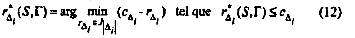
avec c Δ l la capacité théorique par groupe d'antennes d'émission (ou couche):
- ∀Γ partition de S, ∀Δ, ∈ Γ,
- N T the number of transmitting antennas:
- n T the number of active transmit antennas ( n T ≤ N T );
- N R the number of active receiving antennas;
- S the set of transmitting antennas activated, such that S ⊆ {1, ···, N T }, with d the cardinality of the set S: d = | S | ;
- Γ orderly partition of transmit antennas contained in ensmble S K Δ disjoint groups such that ∀ i, ∀ j ≠ i, we have Δ i ∩ Δ j = Ø, defined by Γ = {Δ l, · ··, Δ κ } (the order corresponds to the decoding order):
- Δ a group included in the partition Γ of | Δ | integers {δ 1 , ··· , δ | Δ | };
- R the ordered set of selected discrete returns; and
- T S , Γ the maximum attainable discrete capacitance sum for a given realization of H, S and Γ, given the ST-MCS family available at issue;
we obtain:- ∀Γ partition of S , ∀Δ, ∈ Γ,
with c Δ l the theoretical capacity per emission antenna group (or layer):
- ∀Γ partition of S , ∀Δ, ∈ Γ,
D'un point de vue de la théorie de l'information, le récepteur basé sur un critère MMSE combiné à une soustraction d'interférences successives avec contrôle de rendement par groupe est optimal, sous l'hypothése d'entrées gaussiennes indépendantes.From an information theory point of view, the MMSE-based receiver combined with successive interference subtraction with group efficiency control is optimal, assuming independent Gaussian inputs.
L'extension de cet algorithme de sélection à un autre récepteur, non nécessairement optimal, est évidemment envisageable.The extension of this selection algorithm to another receiver, which is not necessarily optimal, is obviously conceivable.
En particulier, on note que les matrices AΔ i prennent une forme différente en fonction du choix retenu pour le récepteur. Suivant le type de récepteur considéré, ces matrices peuvent être calculées grâce à la connaissance du canal de transmission en réception, ou bien obtenues par estimation sur les symboles pilotes.In particular, we note that the matrices A Δ i take a different form depending on the choice chosen for the receiver. Depending on the type of receiver considered, these matrices can be calculated thanks to the knowledge of the transmission channel in reception, or obtained by estimation on the pilot symbols.
Par exemple, la
On considère pour ce faire que l'algorithme de sélection d'antennes prend en compte deux entrées : une information sur le canal de transmission (par exemple de type estimée du canal de transmission), et un ensemble de jeu de rendements discrets (table des MCS (éventuellement ST-MCS) à considérer).To do this, it is considered that the antenna selection algorithm takes into account two inputs: information on the transmission channel (for example of the estimated transmission channel type), and a set of discrete output sets (table of MCS (possibly ST-MCS) to consider).
Au cours d'une étape d'initialisation 91, on initialise la variable R max, correspondant au rendement maximum que l'on peut atteindre, à la valeur « 0 ».During an
Ensuite, pour chaque i (i entier) tel que l'ensemble des antennes d'émission est Si ⊆ {1,..., N
On détermine ensuite au cours d'une étape 95 les capacités correspondantes : c Δ t = log2 det (I|Δ t | + AΔ t ).Is then determined in a
Au cours d'une étape 96 suivante, les rendements discrets R i,j sont alloués ![]()
![]()
![]()
![]()
Finalement, on compare la somme capacité discrète T i,j et le rendement maximum Rmax , au cours d'une phase de test 97.Finally, we compare the sum discrete capacitance T i , j and the maximum efficiency R max , during a
Si la condition Tt,j ≥ R max est vérifiée (972) alors on pose R max = T i,j , et l'algorithme de sélection stocke les valeurs suivantes (98) :
- S l'ensemble des antennes d'émission sélectionnées, tel que S = St ;
- R l'ensemble ordonné des rendements correspondants, tel que R = Ri,j ;
- Γ la partition ordonnée choisie, telle que Γ = Γ j ;
- S all the selected transmission antennas, such as S = S t ;
- R the ordered set of corresponding yields, such that R = R i, j ;
- Γ the chosen ordered partition, such that Γ = Γ j ;
Si la condition T i,j ≥ R max n'est pas vérifiée (971) alors on passe à l'étape 99. On teste au cours de cette étape 99 si une autre partition est possible. Si oui (992), on incrémente la variable j (j = j + 1), et on retourne à l'étape 93. Sinon (991), on incrémente la variable i (i = i + 1), et on retourne à l'étape 92.If the condition T i , j ≥ R max is not checked (971) then we go to step 99. In this
Cet algorithme, encore appelé premier algorithme, est notamment repris dans l'annexe A, qui fait partie intégrante de la présente description.This algorithm, also called first algorithm, is included in Appendix A, which is an integral part of the present description.
En particulier, il est à noter que la discrétisation de la capacité par flux (c'est-à-dire la capacité pour un des groupes d'antennes d'émission considéré) sur l'ensemble des (ST-)MCS disponibles est réalisée dans l'algorithme de sélection grâce à l'opérateur └·┘ (partie entière), qui permet de choisir le plus proche MCS (ou ST-MCS) par valeur inférieure.In particular, it should be noted that the discretization of the flux capacity (that is to say the capacity for one of the groups of transmit antennas considered) on all (ST-) MCS available is realized in the selection algorithm thanks to the operator └ · ┘ (integer part), which makes it possible to choose the nearest MCS (or ST-MCS) by lower value.
On présente ci-après quelques exemples de réalisation particulière de l'algorithme de sélection :Some examples of particular embodiments of the selection algorithm are presented below:
On considère par exemple que le récepteur est basé sur un critère MMSE suivi d'une succession d'interférences. La matrice AΔ i peut alors s'écrire sous la forme suivante : 
avec :
- H Δ les |Δ| colonnes de la matrice de canal H telles que

- Θx la matrice de covariance du signal d'émission x, Θx =diag{P 1,···,Pd } :
- ΘxΔ les |Δ| éléments diagonaux de la matrice Θx tels que

- † dénote l'opérateur transposé conjugué.
with:
- H Δ the | Δ | columns of the H- channel matrix such as
- Θ x the covariance matrix of the transmission signal x , Θ x = diag { P 1 , ···, P d }:
- Θ xΔ the | Δ | diagonal elements of the matrix Θ x such that
- † denotes the conjugated transposed operator.
On peut alors particulariser l'équation (13) relative à la capacité théorique c Δ t pour un sous-ensemble S et une partition ordonnée Γ. On peut notamment noter que l'ordre de décodage suit l'ordre des groupes de Γ, puisque la partition est considérée ordonnée, c'est-à-dire l'ordre de I à K.We can then particularize the equation (13) relating to the theoretical capacity c Δ t for a subset S and an ordered partition Γ. It can be noted in particular that the decoding order follows the order of the groups of Γ, since the partition is considered ordered, that is to say the order of I to K.
Par ailleurs, dans des conditions de feedback réduit comme indiqué précédemment, la puissance est considérée fixée et, en l'absence de connaissance de canal à l'émission, équidistribuée entre toutes les antennes d'émission actives.Furthermore, under reduced feedback conditions as indicated above, the power is considered fixed and, in the absence of transmission channel knowledge, equidistributed between all the active transmit antennas.
Ainsi, on a : ![]()
![]()
Pour ce type de récepteur, chaque capacité par flux est classiquement calculée à partir d'inversions matricielles, comme dans l'équation (14).For this type of receiver, each capacity per stream is conventionally calculated from matrix inversions, as in equation (14).
Par conséquent, il faut autant d'inversions matricielles de taille NR × NR que de groupes dans l'ensemble S des antennes actives (qui comprend d éléments), chaque inversion présentant une complexité d'ordre 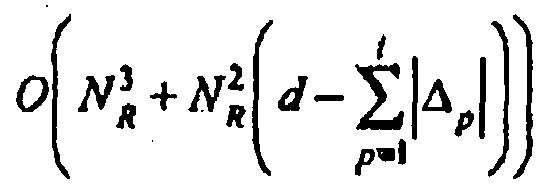
Une autre approche de plus faible complexité permet d'obtenir chaque matrice à inverser par une méthode récursive. De cette manière, une nouvelle valeur B t+1 (équation (18) ci-après) est obtenue en mettant à jour une valeur précédente Bt (équation (15)), où l est le l+1ème groupe d'antennes décodé considéré, avec 0 ≤ l < κ : 
La nouvelle valeur B t+1 est alors obtenue grâce au lemme d'inversion matricielle, aussi appelé identité matricielle de Woodbury, donnée par la relation suivante : ![]()
![]()
On obtient alors : 

![]()
![]()
L'ordre de complexité est ainsi réduit et égal à ![]()
![]()
Le premier algorithme décrit en relation avec la
Ce deuxième algorithme simplifié est notamment repris dans l'annexe B, qui fait partie intégrante de la présente description.This second simplified algorithm is included in Appendix B, which forms an integral part of the present description.
Si le système considéré possède une partition fixée, le premier algorithme et le deuxième algorithme (ainsi que ceux qui en découlent) peuvent se simplifier en cherchant uniquement l'ordre de décodage optimal de la partition fixée.If the considered system has a fixed partition, the first algorithm and the second algorithm (as well as those derived from it) can be simplified by searching only the optimal decoding order of the fixed partition.
Par ailleurs, la recherche exhaustive du meilleur ensemble d'antennes d'émission actives parmi les NT antennes d'émission augmente exponentiellement avec le nombre NT d'antennes d'émission disponibles.Furthermore, the exhaustive search for the best set of active transmit antennas among the N T transmit antennas increases exponentially with the number N T of available transmit antennas.
Par conséquent, afin de diminuer la complexité de cette recherche, différents modes de réalisation sont proposés.Therefore, in order to decrease the complexity of this research, different embodiments are proposed.
Par exemple, un des modes de réalisation repose sur une implémentation itérative partant d'un ensemble S vide. Un autre mode de réalisation repose sur une implémentation itérative partant d'un ensemble S plein, c'est-à-dire comprenant les NT antennes d'émission. En effet, les pertes en performance dues à ces implémentations itératives sont négligeables. De plus, ces deux modes de réalisation aboutissent à la même sélection de l'ensemble S.For example, one of the embodiments relies on an iterative implementation starting from an empty set S. Another embodiment relies on an iterative implementation starting from a set S full, that is to say comprising the N T transmitting antennas. Indeed, the performance losses due to these iterative implementations are negligible. In addition, these two embodiments result in the same selection of the set S.
Par exemple, on présente en relation avec l'annexe C, qui fait partie intégrante de la présente description, l'algorithme de sélection des antennes d'émission, conjointement à la sélection des rendement discrets par antenne, reposant sur un mode de réalisation itératif dit « incrémental », encore noté troisième algorithme. On considère que les matrices AΔ
Plus : précisément, lors de cet algorithme, les antennes d'émission sélectionnées, c'est-à-dire choisies comme activées, sont ajoutées une à une à l'ensemble S.More precisely, during this algorithm, the selected transmission antennas, that is to say those chosen as activated, are added one by one to the set S.
De manière similaire, l'algorithme de sélection des antennes d'émission reposant sur un mode de réalisation itératif dit « décrémental », c'est-à-dire commençant avec un ensemble S d'antennes d'émission plein comprenant les NT antennes d'émission, peut être aisément obtenu à partir de l'algorithme incrémental précédent.Similarly, the transmission antenna selection algorithm relies on an iterative embodiment called "decremental", that is to say starting with a set S of full transmit antennas including the N T antennas of emission, can be easily obtained from the previous incremental algorithm.
Dans ce cas, on soustrait une à une les antennes d'émission si la somme capacité de l'ensemble contenant x antennes est supérieure à celle contenant x+1 antennes.In this case, the transmit antennas are subtracted one by one if the sum capacity of the set containing x antennas is greater than that containing x +1 antennas.
En particulier, dans le cas d'un récepteur MMSE combiné à une succession d'interférences, la façon de calculer les capacités par antenne est effectuée d'une manière semblable à celle décrite en relation avec le premier exemple, c'est-à-dire en utilisant une méthode récursive permettant l'obtention des matrices inverses.In particular, in the case of an MMSE receiver combined with a succession of interferences, the way of calculating the capabilities per antenna is performed in a manner similar to that described in relation to the first example, that is to say using a recursive method for obtaining the inverse matrices.
L'algorithme illusttant la mise en oeuvre de cette technique, noté quatrième algorithme, est notamment présenté en annexe D, qui fait partie intégrante de la présente description.The algorithm illustrating the implementation of this technique, noted fourth algorithm, is in particular presented in Appendix D, which forms an integral part of the present description.
Finalement, afin de réduire davantage la complexité des algorithmes itératifs, il peut être intéressant de n'explorer que l'ordonnancement optimal, ou encore que le choix de partition optimal, à chaque ajout (respectivement à chaque suppression pour la mise en ouvre du mode de réalisation itératif décrémental) d'une antenne d'émission dans l'ensemble S des antennes d'émission actives.Finally, in order to further reduce the complexity of the iterative algorithms, it may be interesting to explore only the optimal scheduling, or the optimal partition choice, at each addition (respectively at each deletion for the implementation of the mode). decremental iterative embodiment) of a transmitting antenna in the set S of active transmission antennas.
Cette simplification conduit dans les troisième et quatrième algorithmes, présentés respectivement en annexe C et en annexe D, à supprimer soit l'étape de recherche de la meilleure partition (étape notée 1.2 dans les annexes), soit l'étape de recherche de la meilleure permutation de l'ensemble S (étape notée 1.2.1 dans les annexes, encore appelée étape de recherche d'un ordonnancement optimal).This simplification leads in the third and fourth algorithms, presented respectively in appendix C and appendix D, to remove either the step of searching for the best score (step noted 1.2 in the appendices), or the step of looking for the best permutation of the set S (step noted 1.2.1 in the appendices, also called step of search of an optimal scheduling).
Ainsi, si par exemple on choisit de supprimer l'étape de recherche de l'ordonnancement optimal, un ordre de décodage fixe est imposé par la façon d'ajouter les éléments dans l'ensemble S pour une procédure de type incrémentale. Lors d'une sélection décrémentale, l'ordre de décodage est fixé lors d'une étape d'initialisation, Il peut par exempte être basé sur un critère de classement des SINRs en sortie du MMSE avant la suppression d'interférences ; on teste la suppression du plus faible à chaque itération.Thus, if for example one chooses to delete the search step of the optimal scheduling, a fixed decoding order is imposed by the way of adding the elements in the set S for an incremental type procedure. During a decremental selection, the decoding order is set during an initialization step. It may, for example, be based on a criterion for classifying the SINRs at the output of the MMSE before the suppression of interference; we test the suppression of the weakest at each iteration.
Cette simplification entraîne cependant une dégradation des performances.This simplification, however, results in a degradation of performance.
On présente finalement, en relation avec les
Un dispositif d'émission comprend une mémoire 41 constituée d'une mémoire tampon, une unité de traitement 42, équipée par exemple d'un microprocesseur µP, et pilotée par le programme d'ordinateur 43, mettant en oeuvre le procédé d'émission selon l'invention.An emission device comprises a
A l'initialisation, les instructions de code du programme d'ordinateur 43 sont par exemple chargées dans une mémoire RAM avant d'être exécutées par le processeur de l'unité de traitement 42. L'unité de traitement 42 reçoit en entrée un flux de données binaires d, et un signal de paramétrage 15. par exemple sous la forme d'un message CQI. Le microprocesseur de l'unité de traitement 42 met en oeuvre les étapes du procédé d'émission décrit précédemment, selon les instructions du programme d'ordinateur 43, pour adapter la répartition des antennes d'émission par groupe et affecter des rendements spécifiques à chacun des groupes, en fonction des rendements disponibles en émission, de façon à optimiser les performances de transmission.At initialization, the code instructions of the
Pour cela, le dispositif d'émission comprend des moyens de réception d'un signal de paramétrage transmis par ledit récepteur, des moyens de sélection d'une des répartitions définies dans le signal de paramétrage, des moyens de répartition des antennes d'émission selon les groupes de la répartition sélectionnée, et des moyens d'attribution à chacun des groupes du rendement spécifique correspondant, défini dans le signal de paramétrage.For this purpose, the transmission device comprises means for receiving a parameterization signal transmitted by said receiver, means for selecting one of the distributions defined in the parameterization signal, means for distributing the transmitting antennas according to the groups of the selected distribution, and means for assigning to each of the groups the corresponding specific efficiency defined in the parameterization signal.
Ces moyens sont pilotés par le microprocesseur de l'unité de traitement 42.These means are controlled by the microprocessor of the
Le dispositif de réception comprend également une mémoire 51, une unité de traitement 52, équipée par exemple d'un microprocesseur µP, et pilotée par le programme d'ordinateur 53, mettant en oeuvre le procédé de réception selon l'invention.The receiving device also comprises a
A l'initialisation, les instructions de code du programme d'ordinateur 53 sont par exemple chargées dans une mémoire RAM avant d'être exécutées par le processeur de l'unité de traitement 52. L'unité de traitement 52 reçoit en entrée un signal reçu 11. Le microprocesseur de l'unité de traitement 52 met en oeuvre les étapes du procédé de réception décrit précédemment, selon les instructions du programme d'ordinateur 53, pour analyser le signal reçu et déterminer un signal de paramétrage 15 définissant au moins une répartition des antennes d'émission en groupes d'antenne(s) et des rendements spécifiques affectés respectivement à chacun des groupes d'antennes pour chaque répartition, en fonction d'une information représentative du canal de transmission.At initialization, the code instructions of the
Pour cela, le dispositif de réception comprend des moyens d'analyse du signal reçu, délivrant une information représentative du canal de transmission, des moyens de détermination, en fonction de l'information représentative du canal de transmission :
- d'au moins une répartition desdites antennes d'émission en groupes d'antenne(s) ;
- des rendements spécifiques affectés respectivement à chacun desdits groupes d'antennes pour chaque répartition,
- at least one distribution of said transmitting antennas into antenna groups;
- specific yields respectively assigned to each of said groups of antennas for each distribution,
-
Entrées: a. information sur la qualité du canal.
- b. jeu de rendements discrets
- b. game of discrete returns
-
Initialisation Rmax = 0 ;
Initialization R max = 0;

-
Sorties: a. S l'ensemble des antennes sélectionnées,
- b. R l'ensemble ordonné des rendements correspondants
- c. Γ la partition ordonnée choisie
- b. R the ordered set of corresponding yields
- vs. Γ the ordered partition chosen
-
Entrées: a. information sur la qualité du canal.
- b. jeu de rendements discrets
- b. game of discrete returns
-
Initialisation Rmax = 0 :
Initialization R max = 0:

-
Sorties: a. S l'ensemble des antennes sélectionées,
- b. R l'ensemble ordonné des rendements correspondants
- c. Γ la partition ordonnée choisie
- b. R the ordered set of corresponding yields
- vs. Γ the ordered partition chosen
-
Entrées: a. information sur la qualité du canal.
- b. jeu de rendements discrets
- b. game of discrete returns
-
Initialisation Rmax = 0 ;
- S = 0 :
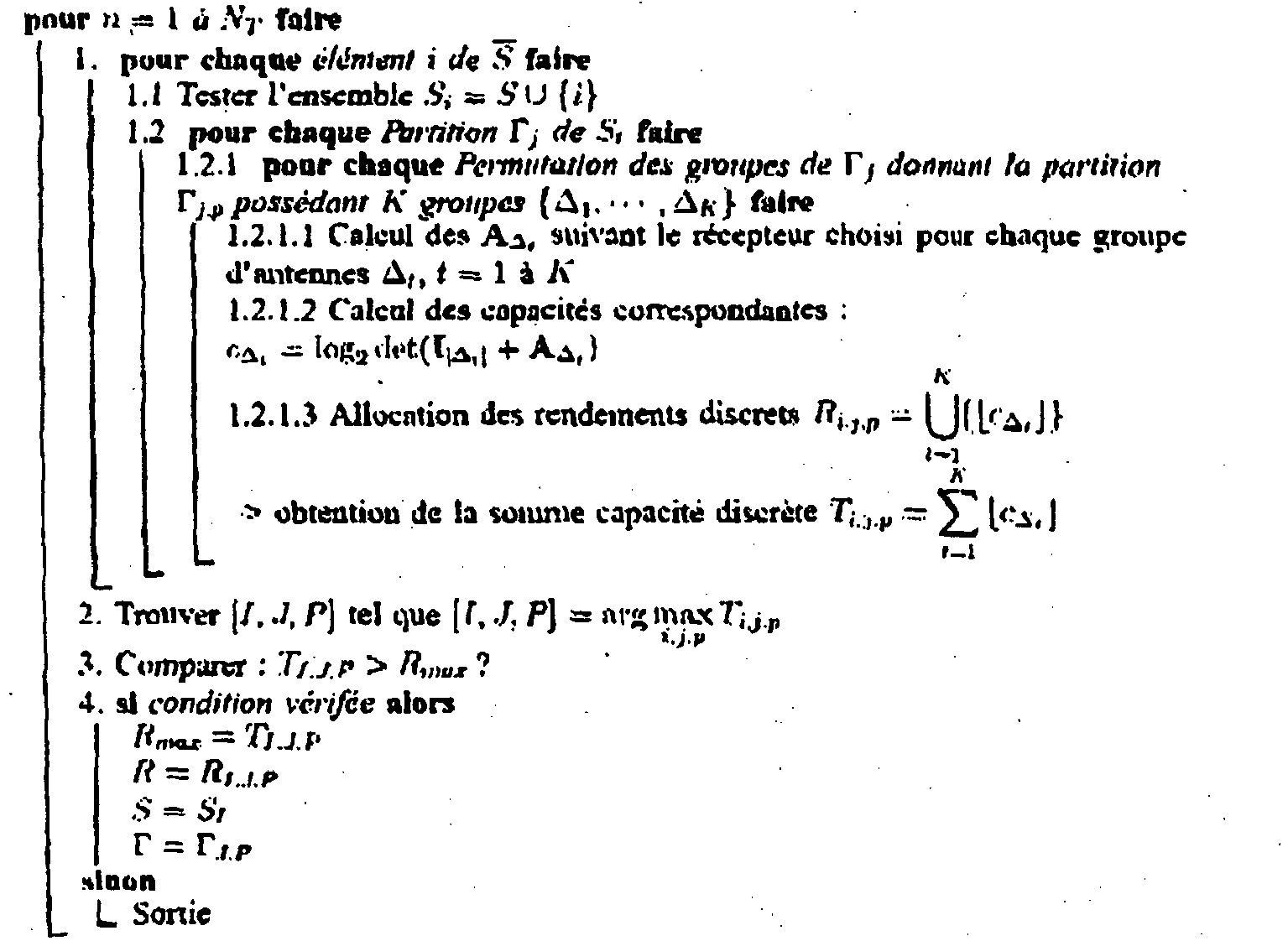
- S = 0:
- S = 0 :
-
Sorties: a. S l'ensemble des antennes sélectionnées,
- b. R l'ensemble ordonné des rendements correspondants
- c. Γ la partition ordonnée choisie
- b. R the ordered set of corresponding yields
- vs. Γ the ordered partition chosen
-
Entrées: a. information sur la qualité du canal,
- b. jeu de rendements discrets
- Initialisation Rmax = 0 ;
- S = 0 ;

- b. game of discrete returns
- Initialization R max = 0;
- S = 0;
-
Sorties: a. S l'ensemble des antennes sélectionnées,
- b. R l'ensemble ordonné des rendements correspondants
- c. Γ la partition ordonnée choisie
- b. R the ordered set of corresponding yields
- vs. Γ the ordered partition chosen
Claims (15)
- Method for reception of a received signal (11), corresponding to a data signal transmitted by a transmitter to a receiver via a transmission channel, said transmitter comprising NT transmission antennas and said receiver comprising NR reception antennas, with NT and NR greater than or equal to 2,
characterized in that it comprises the following steps:- analysis (12) of said received signal, delivering an item of information (14) representative of said transmission channel;- determination, periodically or as a function of a variation in said transmission channel:■ of at least one distribution of said transmission antennas into at least one group of at least one antenna, as a function of said item of information representative of the transmission channel,■ of the specific rates assigned to each of said groups of antennas respectively, for each distribution as a function of said item of information representative of the transmission channel;
at least one group comprising at least two transmission antennas for at least one of said determinations;- transmission to said transmitter of a parameterization signal (15) defining said distribution or distributions and said specific rates. - Reception method according to Claim 1, characterized in that said analysis and transmission steps are also implemented periodically and/or as a function of a variation in said transmission channel.
- Reception method according to any one of Claims 1 and 2, characterized in that said determination step determines specific powers allocated to each of said transmission antennas respectively, and in that said parameterization signal (15) also defines said powers.
- Reception method according to any one of Claims 1 to 3, characterized in that it comprises a step of selection of transmission antennas among said NT transmission antennas, called active antennas, at least as a function of said item of information (14) representative of the transmission channel,
and in that said parameterization signal (15) defines said active antennas. - Reception method according to Claim 4, characterized in that said selection step is implemented jointly with said determination step.
- Reception method according to any one of Claims 4 and 5, characterized in that an optimized ordered distribution Γ*, the specific rates per group R* for this distribution, and an optimized set S* of the active antennas, are determined from the following equations:such thatwhere:


 - H is representative of said transmission channel;- ρ corresponds to the signal-to-noise ratio;- {P1,...,PNT } corresponds to a set of transmission powers attributed to each transmission antenna;- J |Δ| corresponds to a set of discrete rates available for transmission;- Δ corresponds to a group included in the distribution Γ;- AΔ is a matrix representative of said receiver.
 - Reception method according to any one of Claims 1 to 6, characterized in that said at least one distribution is determined by taking into account at least one of the elements belonging to the group comprising:- discrete rates available for transmission;- powers associated with each distribution into groups of said transmission antennas;- an order of decoding implemented at the level of said receiver;- the number NR of reception antennas;- a number of active transmission antennas.
- Reception method according to any one of Claims 1 to 7, characterized in that it implements a step of determination of an ordering of said groups, and a step of decoding implemented successively for each group following said ordering.
- Reception method according to Claim 8, characterized in that said ordering minimizes a metric taking into account the distributions into groups of said transmission antennas and/or the powers provided by said transmission antennas and/or the specific rates and/or an order of decoding.
- Method for transmission of a data signal from a transmitter to a receiver via a transmission channel, said transmitter comprising NT transmission antennas and said receiver comprising NR reception antennas, with NT and NR greater than or equal to 2,
characterized in that it comprises the following steps:- reception of a parameterization signal (15) transmitted by said receiver defining:■ at least one distribution of said transmission antennas into at least one group of at least one antenna;■ specific rates assigned to each of said groups of antennas respectively, for each distribution;■ obtained as a function of an item of information representative of the transmission channel, by determination periodically or as a function of a variation in the transmission channel;■ at least one group comprising at least two transmission antennas for at least one determination;- selection of one of said distributions among said distribution or distributions defined in said parameterization signal (15);- distribution of said transmission antennas into the groups of said selected distribution;- attribution to each of said groups of the corresponding specific rate, defined in said parameterization signal (15). - Device for reception of a received signal (11), corresponding to a data signal transmitted by a transmitter via a transmission channel, said transmitter comprising NT transmission antennas and said reception device comprising NR reception antennas, with NT and NR greater than or equal to 2,
characterized in that it comprises:- means for analysis of said received signal (11), delivering an item of information (14) representative of said transmission channel;- means for determination, periodically or as a function of a variation in said transmission channel:■ of at least one distribution of said transmission antennas into at least one group of at least one antenna, as a function of said item of information representative of the transmission channel,■ of the specific rates assigned to each of said groups of antennas respectively, for each distribution as a function of said item of information representative of the transmission channel;
at least one group comprising at least two transmission antennas for at least one of said determinations;- means for transmission to said transmitter of a parameterization signal (15) defining said distribution or distributions and said specific rates. - Device for transmission of a data signal to a receiver via a transmission channel, said transmission device comprising NT transmission antennas and said receiver comprising NR reception antennas, with NT and NR greater than or equal to 2,
characterized in that it comprises:- means for reception of a parameterization signal (15) transmitted by said receiver defining:■ at least one distribution of said transmission antennas into at least one group of at least one antenna;■ specific rates assigned to each of said groups of antennas respectively, for each distribution;
obtained, as a function of an item of information representative of the transmission channel, by determination, periodically or as a function of a variation in the transmission channel,
at least one group comprising at least two transmission antennas for at least one determination,- means for selection of one of said distributions among said distribution or distributions defined in said parameterization signal;- means for distribution of said transmission antennas into the groups of said selected distribution;- means for attribution to each of said groups of the corresponding specific rate, defined in said parameterization signal. - Computer program product downloadable from a communication network and/or stored on a medium readable by computer and/or executable by a processor, characterized in that it comprises program code instructions for the implementation of the reception method according to at least one of Claims 1 to 9.
- Computer program product downloadable from a communication network and/or stored on a medium readable by computer and/or executable by a processor, characterized in that it comprises program code instructions for the implementation of the transmission method according to Claim 10.
- Parameterization signal of a transmitter, transmitted from a receiver to said transmitter via a transmission channel, said transmitter comprising NT transmission antennas and said receiver comprising NR reception antennas, with NT and NR greater than or equal to 2,
characterized in that it comprises at least one parameterization field comprising:- an item of information relating to at least one distribution of said transmission antennas into at least one group of at least one antenna; and- an item of information relating to specific rates assigned to each of said groups of antennas respectively, for each distribution,at least one group comprising at least two transmission antennas for at least one determination.
obtained, as a function of an item of information representative of said transmission channel, by determination periodically or as a function of a variation in the transmission channel,
Applications Claiming Priority (3)
| Application Number | Priority Date | Filing Date | Title |
|---|---|---|---|
| FR0608021 | 2006-09-13 | ||
| FR0611136 | 2006-12-20 | ||
| PCT/FR2007/001487 WO2008031951A2 (en) | 2006-09-13 | 2007-09-13 | Adaptive method of transmitting and receiving a signal in a multi-antenna system, corresponding transmission and reception devices, computer program products and signal |
Publications (2)
| Publication Number | Publication Date |
|---|---|
| EP2062377A2 EP2062377A2 (en) | 2009-05-27 |
| EP2062377B1 true EP2062377B1 (en) | 2014-04-09 |
Family
ID=39144299
Family Applications (1)
| Application Number | Title | Priority Date | Filing Date |
|---|---|---|---|
| EP07848227.0A Active EP2062377B1 (en) | 2006-09-13 | 2007-09-13 | Adaptive method of transmitting and receiving a signal in a multi-antenna system, corresponding transmission and reception devices, computer program products and signal |
Country Status (3)
| Country | Link |
|---|---|
| US (1) | US8412114B2 (en) |
| EP (1) | EP2062377B1 (en) |
| WO (1) | WO2008031951A2 (en) |
Families Citing this family (6)
| Publication number | Priority date | Publication date | Assignee | Title |
|---|---|---|---|---|
| EP2282471A1 (en) * | 2009-08-07 | 2011-02-09 | Thomson Licensing | Data transmission using low density parity check coding and constellation mapping |
| EP2282470A1 (en) | 2009-08-07 | 2011-02-09 | Thomson Licensing | Data reception using low density parity check coding and constellation mapping |
| WO2011103912A1 (en) * | 2010-02-23 | 2011-09-01 | Nokia Siemens Networks Oy | Transmitting in non-beamforming mode with a beamforming antenna array |
| WO2011114329A1 (en) * | 2010-03-16 | 2011-09-22 | Levi Lior Guttman | Signaling device |
| JP5327171B2 (en) * | 2010-09-15 | 2013-10-30 | オムロン株式会社 | RFID system |
| US11172477B2 (en) | 2018-11-02 | 2021-11-09 | Qualcomm Incorproated | Multi-transport block scheduling |
Family Cites Families (8)
| Publication number | Priority date | Publication date | Assignee | Title |
|---|---|---|---|---|
| WO2002003557A1 (en) | 2000-06-30 | 2002-01-10 | Iospan Wireless, Inc. | Method and system for mode adaptation in wireless communication |
| US7072413B2 (en) * | 2001-05-17 | 2006-07-04 | Qualcomm, Incorporated | Method and apparatus for processing data for transmission in a multi-channel communication system using selective channel inversion |
| ATE338388T1 (en) | 2002-04-30 | 2006-09-15 | Motorola Inc | WIRELESS COMMUNICATION USING MULTIPLE TRANSMIT AND RECEIVE ANTENNA ARRANGEMENT |
| US7583745B2 (en) * | 2003-12-03 | 2009-09-01 | Nokia Corporation | Exploiting selection diversity in communications systems with non-orthonormal matrix and vector modulation |
| US8249518B2 (en) * | 2003-12-29 | 2012-08-21 | Telefonaktiebolaget Lm Ericsson (Publ) | Network controlled feedback for MIMO systems |
| US8045638B2 (en) * | 2004-03-05 | 2011-10-25 | Telefonaktiebolaget Lm Ericsson (Publ) | Method and apparatus for impairment correlation estimation in a wireless communication receiver |
| KR100648472B1 (en) * | 2004-10-19 | 2006-11-28 | 삼성전자주식회사 | Apparatus and method of transmitting and receiving for optimizing of performance of amc in multi-input multi-output system |
| US8634432B2 (en) * | 2005-05-06 | 2014-01-21 | Samsung Electronics Co., Ltd. | System and method for subcarrier allocation in a multicarrier wireless network |
-
2007
- 2007-09-13 US US12/441,057 patent/US8412114B2/en active Active
- 2007-09-13 EP EP07848227.0A patent/EP2062377B1/en active Active
- 2007-09-13 WO PCT/FR2007/001487 patent/WO2008031951A2/en active Application Filing
Also Published As
| Publication number | Publication date |
|---|---|
| US20100003934A1 (en) | 2010-01-07 |
| WO2008031951A3 (en) | 2008-06-12 |
| US8412114B2 (en) | 2013-04-02 |
| WO2008031951A2 (en) | 2008-03-20 |
| EP2062377A2 (en) | 2009-05-27 |
Similar Documents
| Publication | Publication Date | Title |
|---|---|---|
| US10056996B2 (en) | Techniques to manage channel prediction | |
| KR100977434B1 (en) | A method and apparatus for pre-coding for a mimo system | |
| US7773685B2 (en) | Transmitting and receiving methods | |
| US7428269B2 (en) | CQI and rank prediction for list sphere decoding and ML MIMO receivers | |
| US8971461B2 (en) | CQI and rank prediction for list sphere decoding and ML MIMO receivers | |
| EP2062377B1 (en) | Adaptive method of transmitting and receiving a signal in a multi-antenna system, corresponding transmission and reception devices, computer program products and signal | |
| US8175181B1 (en) | Method and apparatus for selecting a modulation coding scheme | |
| US9215121B1 (en) | Method and apparatus for implementing transmit diversity in OFDM systems | |
| WO2005057838A1 (en) | Method for the multi-antenna transmission of a linearly-precoded signal, corresponding devices, signal and reception method | |
| EP2517365B1 (en) | Method for selecting a transmission mode | |
| FR2894416A1 (en) | METHOD AND DEVICE FOR SELECTING THE SPREAD PARAMETERS OF A CDMA OFDM SYSTEM | |
| KR101124338B1 (en) | Mimo-based data transmission method | |
| EP1367760B1 (en) | Transmit/receive diversity wireless communication | |
| EP3075088B1 (en) | Method of coordinating radio transmitters based on a coding of level of power transmitted and corresponding transmitter | |
| KR100896443B1 (en) | Apparatus and method for transmitting and receiving in multi-user multi-antenna communication systems | |
| EP3800813B1 (en) | Method and device for predicting the performance of a receiver in a communication system | |
| EP4078839A1 (en) | Transmission and reception methods and devices implementing a plurality of transmit and receive antennas, and corresponding computer program | |
| EP2193611B1 (en) | Method for emitting and receiving a signal in a multi-antenna system, using spatial precoding, and corresponding emitter, receiver, and computer program products | |
| EP3329609B1 (en) | Method for processing information representing a channel for transmission by a radio system, associated device, receiver system and computer program | |
| WO2023118055A1 (en) | Method for selecting a plurality of receivers, and corresponding transmitter and computer program | |
| WO2023118056A1 (en) | Method for communicating between a transmitter and a receiver for optimizing beamforming, corresponding transmitter, receiver and computer program | |
| US20240039589A1 (en) | Improvements to mimo systems | |
| FR2952239A1 (en) | METHOD AND DEVICE FOR RECEIVING MONO AND MULTI-ANTENNA FOR ALAMOUTI-LIKE CONNECTIONS | |
| CA2650461A1 (en) | Frequency hopping of pilot tones | |
| FR3118551A1 (en) | Method of receiving at least one data frame in an OMAMRC system, corresponding destination, computer program and system. |
Legal Events
| Date | Code | Title | Description |
|---|---|---|---|
| PUAI | Public reference made under article 153(3) epc to a published international application that has entered the european phase |
Free format text: ORIGINAL CODE: 0009012 |
|
| 17P | Request for examination filed |
Effective date: 20081223 |
|
| AK | Designated contracting states |
Kind code of ref document: A2 Designated state(s): AT BE BG CH CY CZ DE DK EE ES FI FR GB GR HU IE IS IT LI LT LU LV MC MT NL PL PT RO SE SI SK TR |
|
| AX | Request for extension of the european patent |
Extension state: AL BA HR MK RS |
|
| 17Q | First examination report despatched |
Effective date: 20091109 |
|
| DAX | Request for extension of the european patent (deleted) | ||
| REG | Reference to a national code |
Ref country code: DE Ref legal event code: R079 Ref document number: 602007036061 Country of ref document: DE Free format text: PREVIOUS MAIN CLASS: H04B0007060000 Ipc: H04B0007040000 |
|
| RIC1 | Information provided on ipc code assigned before grant |
Ipc: H04L 1/00 20060101ALI20130708BHEP Ipc: H04L 1/06 20060101ALI20130708BHEP Ipc: H04B 7/06 20060101ALI20130708BHEP Ipc: H04B 7/04 20060101AFI20130708BHEP |
|
| GRAP | Despatch of communication of intention to grant a patent |
Free format text: ORIGINAL CODE: EPIDOSNIGR1 |
|
| RAP1 | Party data changed (applicant data changed or rights of an application transferred) |
Owner name: ORANGE |
|
| INTG | Intention to grant announced |
Effective date: 20130919 |
|
| GRAP | Despatch of communication of intention to grant a patent |
Free format text: ORIGINAL CODE: EPIDOSNIGR1 |
|
| INTG | Intention to grant announced |
Effective date: 20131107 |
|
| GRAS | Grant fee paid |
Free format text: ORIGINAL CODE: EPIDOSNIGR3 |
|
| GRAA | (expected) grant |
Free format text: ORIGINAL CODE: 0009210 |
|
| AK | Designated contracting states |
Kind code of ref document: B1 Designated state(s): AT BE BG CH CY CZ DE DK EE ES FI FR GB GR HU IE IS IT LI LT LU LV MC MT NL PL PT RO SE SI SK TR |
|
| REG | Reference to a national code |
Ref country code: GB Ref legal event code: FG4D Free format text: NOT ENGLISH |
|
| REG | Reference to a national code |
Ref country code: AT Ref legal event code: REF Ref document number: 661822 Country of ref document: AT Kind code of ref document: T Effective date: 20140415 Ref country code: CH Ref legal event code: EP |
|
| REG | Reference to a national code |
Ref country code: IE Ref legal event code: FG4D Free format text: LANGUAGE OF EP DOCUMENT: FRENCH |
|
| REG | Reference to a national code |
Ref country code: DE Ref legal event code: R096 Ref document number: 602007036061 Country of ref document: DE Effective date: 20140522 |
|
| REG | Reference to a national code |
Ref country code: AT Ref legal event code: MK05 Ref document number: 661822 Country of ref document: AT Kind code of ref document: T Effective date: 20140409 |
|
| REG | Reference to a national code |
Ref country code: NL Ref legal event code: VDEP Effective date: 20140409 |
|
| REG | Reference to a national code |
Ref country code: LT Ref legal event code: MG4D |
|
| PG25 | Lapsed in a contracting state [announced via postgrant information from national office to epo] |
Ref country code: FI Free format text: LAPSE BECAUSE OF FAILURE TO SUBMIT A TRANSLATION OF THE DESCRIPTION OR TO PAY THE FEE WITHIN THE PRESCRIBED TIME-LIMIT Effective date: 20140409 Ref country code: LT Free format text: LAPSE BECAUSE OF FAILURE TO SUBMIT A TRANSLATION OF THE DESCRIPTION OR TO PAY THE FEE WITHIN THE PRESCRIBED TIME-LIMIT Effective date: 20140409 Ref country code: NL Free format text: LAPSE BECAUSE OF FAILURE TO SUBMIT A TRANSLATION OF THE DESCRIPTION OR TO PAY THE FEE WITHIN THE PRESCRIBED TIME-LIMIT Effective date: 20140409 Ref country code: IS Free format text: LAPSE BECAUSE OF FAILURE TO SUBMIT A TRANSLATION OF THE DESCRIPTION OR TO PAY THE FEE WITHIN THE PRESCRIBED TIME-LIMIT Effective date: 20140809 Ref country code: BG Free format text: LAPSE BECAUSE OF FAILURE TO SUBMIT A TRANSLATION OF THE DESCRIPTION OR TO PAY THE FEE WITHIN THE PRESCRIBED TIME-LIMIT Effective date: 20140709 Ref country code: GR Free format text: LAPSE BECAUSE OF FAILURE TO SUBMIT A TRANSLATION OF THE DESCRIPTION OR TO PAY THE FEE WITHIN THE PRESCRIBED TIME-LIMIT Effective date: 20140710 |
|
| PG25 | Lapsed in a contracting state [announced via postgrant information from national office to epo] |
Ref country code: AT Free format text: LAPSE BECAUSE OF FAILURE TO SUBMIT A TRANSLATION OF THE DESCRIPTION OR TO PAY THE FEE WITHIN THE PRESCRIBED TIME-LIMIT Effective date: 20140409 Ref country code: LV Free format text: LAPSE BECAUSE OF FAILURE TO SUBMIT A TRANSLATION OF THE DESCRIPTION OR TO PAY THE FEE WITHIN THE PRESCRIBED TIME-LIMIT Effective date: 20140409 Ref country code: SE Free format text: LAPSE BECAUSE OF FAILURE TO SUBMIT A TRANSLATION OF THE DESCRIPTION OR TO PAY THE FEE WITHIN THE PRESCRIBED TIME-LIMIT Effective date: 20140409 Ref country code: PL Free format text: LAPSE BECAUSE OF FAILURE TO SUBMIT A TRANSLATION OF THE DESCRIPTION OR TO PAY THE FEE WITHIN THE PRESCRIBED TIME-LIMIT Effective date: 20140409 Ref country code: ES Free format text: LAPSE BECAUSE OF FAILURE TO SUBMIT A TRANSLATION OF THE DESCRIPTION OR TO PAY THE FEE WITHIN THE PRESCRIBED TIME-LIMIT Effective date: 20140409 |
|
| PG25 | Lapsed in a contracting state [announced via postgrant information from national office to epo] |
Ref country code: PT Free format text: LAPSE BECAUSE OF FAILURE TO SUBMIT A TRANSLATION OF THE DESCRIPTION OR TO PAY THE FEE WITHIN THE PRESCRIBED TIME-LIMIT Effective date: 20140811 |
|
| REG | Reference to a national code |
Ref country code: DE Ref legal event code: R097 Ref document number: 602007036061 Country of ref document: DE |
|
| PG25 | Lapsed in a contracting state [announced via postgrant information from national office to epo] |
Ref country code: EE Free format text: LAPSE BECAUSE OF FAILURE TO SUBMIT A TRANSLATION OF THE DESCRIPTION OR TO PAY THE FEE WITHIN THE PRESCRIBED TIME-LIMIT Effective date: 20140409 Ref country code: RO Free format text: LAPSE BECAUSE OF FAILURE TO SUBMIT A TRANSLATION OF THE DESCRIPTION OR TO PAY THE FEE WITHIN THE PRESCRIBED TIME-LIMIT Effective date: 20140409 Ref country code: SK Free format text: LAPSE BECAUSE OF FAILURE TO SUBMIT A TRANSLATION OF THE DESCRIPTION OR TO PAY THE FEE WITHIN THE PRESCRIBED TIME-LIMIT Effective date: 20140409 Ref country code: DK Free format text: LAPSE BECAUSE OF FAILURE TO SUBMIT A TRANSLATION OF THE DESCRIPTION OR TO PAY THE FEE WITHIN THE PRESCRIBED TIME-LIMIT Effective date: 20140409 Ref country code: CZ Free format text: LAPSE BECAUSE OF FAILURE TO SUBMIT A TRANSLATION OF THE DESCRIPTION OR TO PAY THE FEE WITHIN THE PRESCRIBED TIME-LIMIT Effective date: 20140409 |
|
| PLBE | No opposition filed within time limit |
Free format text: ORIGINAL CODE: 0009261 |
|
| STAA | Information on the status of an ep patent application or granted ep patent |
Free format text: STATUS: NO OPPOSITION FILED WITHIN TIME LIMIT |
|
| 26N | No opposition filed |
Effective date: 20150112 |
|
| PG25 | Lapsed in a contracting state [announced via postgrant information from national office to epo] |
Ref country code: IT Free format text: LAPSE BECAUSE OF FAILURE TO SUBMIT A TRANSLATION OF THE DESCRIPTION OR TO PAY THE FEE WITHIN THE PRESCRIBED TIME-LIMIT Effective date: 20140409 |
|
| REG | Reference to a national code |
Ref country code: DE Ref legal event code: R097 Ref document number: 602007036061 Country of ref document: DE Effective date: 20150112 |
|
| PG25 | Lapsed in a contracting state [announced via postgrant information from national office to epo] |
Ref country code: MC Free format text: LAPSE BECAUSE OF FAILURE TO SUBMIT A TRANSLATION OF THE DESCRIPTION OR TO PAY THE FEE WITHIN THE PRESCRIBED TIME-LIMIT Effective date: 20140409 Ref country code: LU Free format text: LAPSE BECAUSE OF FAILURE TO SUBMIT A TRANSLATION OF THE DESCRIPTION OR TO PAY THE FEE WITHIN THE PRESCRIBED TIME-LIMIT Effective date: 20140913 |
|
| REG | Reference to a national code |
Ref country code: CH Ref legal event code: PL |
|
| REG | Reference to a national code |
Ref country code: IE Ref legal event code: MM4A |
|
| PG25 | Lapsed in a contracting state [announced via postgrant information from national office to epo] |
Ref country code: BE Free format text: LAPSE BECAUSE OF NON-PAYMENT OF DUE FEES Effective date: 20140930 |
|
| PG25 | Lapsed in a contracting state [announced via postgrant information from national office to epo] |
Ref country code: LI Free format text: LAPSE BECAUSE OF NON-PAYMENT OF DUE FEES Effective date: 20140930 Ref country code: CH Free format text: LAPSE BECAUSE OF NON-PAYMENT OF DUE FEES Effective date: 20140930 Ref country code: SI Free format text: LAPSE BECAUSE OF FAILURE TO SUBMIT A TRANSLATION OF THE DESCRIPTION OR TO PAY THE FEE WITHIN THE PRESCRIBED TIME-LIMIT Effective date: 20140409 |
|
| PG25 | Lapsed in a contracting state [announced via postgrant information from national office to epo] |
Ref country code: IE Free format text: LAPSE BECAUSE OF NON-PAYMENT OF DUE FEES Effective date: 20140913 |
|
| PG25 | Lapsed in a contracting state [announced via postgrant information from national office to epo] |
Ref country code: MT Free format text: LAPSE BECAUSE OF FAILURE TO SUBMIT A TRANSLATION OF THE DESCRIPTION OR TO PAY THE FEE WITHIN THE PRESCRIBED TIME-LIMIT Effective date: 20140409 Ref country code: CY Free format text: LAPSE BECAUSE OF FAILURE TO SUBMIT A TRANSLATION OF THE DESCRIPTION OR TO PAY THE FEE WITHIN THE PRESCRIBED TIME-LIMIT Effective date: 20140409 |
|
| REG | Reference to a national code |
Ref country code: DE Ref legal event code: R081 Ref document number: 602007036061 Country of ref document: DE Owner name: 3G LICENSING S.A., LU Free format text: FORMER OWNER: ORANGE, PARIS, FR |
|
| PG25 | Lapsed in a contracting state [announced via postgrant information from national office to epo] |
Ref country code: HU Free format text: LAPSE BECAUSE OF FAILURE TO SUBMIT A TRANSLATION OF THE DESCRIPTION OR TO PAY THE FEE WITHIN THE PRESCRIBED TIME-LIMIT; INVALID AB INITIO Effective date: 20070913 Ref country code: TR Free format text: LAPSE BECAUSE OF FAILURE TO SUBMIT A TRANSLATION OF THE DESCRIPTION OR TO PAY THE FEE WITHIN THE PRESCRIBED TIME-LIMIT Effective date: 20140409 |
|
| REG | Reference to a national code |
Ref country code: FR Ref legal event code: PLFP Year of fee payment: 10 |
|
| REG | Reference to a national code |
Ref country code: FR Ref legal event code: PLFP Year of fee payment: 11 |
|
| REG | Reference to a national code |
Ref country code: FR Ref legal event code: PLFP Year of fee payment: 12 |
|
| REG | Reference to a national code |
Ref country code: GB Ref legal event code: 732E Free format text: REGISTERED BETWEEN 20190905 AND 20190911 |
|
| PGFP | Annual fee paid to national office [announced via postgrant information from national office to epo] |
Ref country code: GB Payment date: 20230823 Year of fee payment: 17 |
|
| PGFP | Annual fee paid to national office [announced via postgrant information from national office to epo] |
Ref country code: FR Payment date: 20230822 Year of fee payment: 17 Ref country code: DE Payment date: 20230822 Year of fee payment: 17 |