EP2061693B1 - Fahrradaufhängung - Google Patents
Fahrradaufhängung Download PDFInfo
- Publication number
- EP2061693B1 EP2061693B1 EP07789280A EP07789280A EP2061693B1 EP 2061693 B1 EP2061693 B1 EP 2061693B1 EP 07789280 A EP07789280 A EP 07789280A EP 07789280 A EP07789280 A EP 07789280A EP 2061693 B1 EP2061693 B1 EP 2061693B1
- Authority
- EP
- European Patent Office
- Prior art keywords
- suspension
- suspension system
- rear wheel
- linkage
- mounting member
- Prior art date
- Legal status (The legal status is an assumption and is not a legal conclusion. Google has not performed a legal analysis and makes no representation as to the accuracy of the status listed.)
- Not-in-force
Links
Images


Classifications
-
- B—PERFORMING OPERATIONS; TRANSPORTING
- B62—LAND VEHICLES FOR TRAVELLING OTHERWISE THAN ON RAILS
- B62K—CYCLES; CYCLE FRAMES; CYCLE STEERING DEVICES; RIDER-OPERATED TERMINAL CONTROLS SPECIALLY ADAPTED FOR CYCLES; CYCLE AXLE SUSPENSIONS; CYCLE SIDE-CARS, FORECARS, OR THE LIKE
- B62K25/00—Axle suspensions
- B62K25/04—Axle suspensions for mounting axles resiliently on cycle frame or fork
- B62K25/28—Axle suspensions for mounting axles resiliently on cycle frame or fork with pivoted chain-stay
- B62K25/286—Axle suspensions for mounting axles resiliently on cycle frame or fork with pivoted chain-stay the shock absorber being connected to the chain-stay via a linkage mechanism
Definitions
- This invention relates to a suspension system for a two wheeled vehicle, particularly but not exclusively an all-terrain bicycle.
- a rear suspension for a two wheel vehicle is utilised to isolate the operator, the rider, from the impacts and undulations of the terrain whilst maintaining rider control.
- instant centre also known as the virtual pivot point
- instant centre refers to the location of the centre point of the curvature of the wheel path at any point throughout the suspension movement. This point is found on a four bar linkage by extrapolating the straight line between the pivots on the upper and lower links. Where these two extrapolated lines cross is the instant centre. It can be seen that as the rear suspension moves and the position of the upper and lower links changes the position of the instant centre moves.
- the instant centre can migrate throughout the wheel travel and can cause unwanted handling phenomena such as an increase in chain length of the tensioned section of the chain, this leads to an effect known as pedal kickback where the alteration in distance between the front and rear sprockets forces one of the sprockets to rotate.
- pedal kickback where the alteration in distance between the front and rear sprockets forces one of the sprockets to rotate.
- the front sprocket tends to rotate causing the pedals to turn either backwards against the direction of power input, or to rapidly turn forwards due to a shortening of the chain length. This unbalances the rider.
- pedal induced forces and braking forces can cause squat and jacking respectively.
- the rear wheel contact patch tends to move forwards as it rises throughout its suspension travel.
- the forward movement is usually in an almost opposing direction to the force being transmitted from a bump.
- a force is transmitted through the wheel that will try to move the wheel upwards and slightly rearwards. If the wheel is restricted to travelling forwards causing a reduction in wheelbase as it rises, then it equates to a loss of energy over rough ground which may unsettle a rider by trying to pitch them forward.
- An alteration in wheelbase also changes the handling characteristics. A reduction in wheelbase usually leads to a less stable handling vehicle.
- the design is intended to give an anti-squat curve in the initial part of the suspension travel, which decreases as the suspension moves deeper into its travel.
- the Applicant has determined that this arrangement gives uncontrolled movement of the rear axle path and indeed it is noted that at the far end of this travel the rear axle ends up forward of its initial position. This is undesirable, inter alia as it alters the chain length.
- the Applicant has also determined that the arrangement disclosed therein gives a large degree of instant centre migration, which is exacerbated by being relatively flat and horizontal. This is disadvantageous as set out above and contributes to a strong coupling between pedal forces and suspension movement.
- the present invention aims to improve on existing suspension systems and provides a suspension system for a bicycle that is characterised over US 2006/0071444 in that the upper linkage is longer than the lower linkage.
- the linkages are relatively long and that they attach to the chassis relatively close together (compared to either of their lengths) with the upper linkage being longer than the lower linkage. This has been found to give several significant benefits as described below.
- the primary advantage which the invention gives is that migration of the instant centre is significantly reduced as compared to that present in prior art arrangements, especially that shown in WO 2005/ 030564 . This in turn gives a high degree of anti-squat which is maintained throughout the suspension travel.
- a further advantage is that the rear axle follows a rearward and upward path which maintains a substantially constant wheelbase. This increases control as both the front and rear suspension cycle through their travel.
- a jockey wheel mounted on the chassis to act on the chain.
- the jockey wheel is positioned such that it provides a tensioned portion of chain which passes through the instant centre line, that is the line described by the instant centre throughout the suspension travel.
- the jockey wheel is positioned so that the tensioned section of chain lies on a line that passes through the instant-centre.
- the tensioned section of chain, or the line on which it lies preferably passes through the instant centre somewhere between a quarter and half-way through the suspension travel, preferably approximately a third of the way through the suspension travel.
- the chain or the line on which it lies passes through the instant centre at the mid-travel of the suspension.
- top and bottom linkages differ in length with the upper linkage being longer than the lower linkage. This has been found to maximise the benefits referred to above, particularly with the jockey wheel being employed.
- the separation of the first and third pivot points on the rear wheel mounting member is greater than the lengths of both of the upper and lower linkages.
- the length of a linkage is to be taken as the distance between its pivot points.
- linkages could be single pieces but in general will be composite.
- one or both of the linkages comprises a pair of parallel plates.
- the suspension system is arranged such that the instant centre is located behind the front wheel axle and above the front sprocket throughout the range of suspension movement.
- the rear wheel mounting member could take any form but preferably is generally triangular. This enhances its stiffness.
- the first and third pivot points are preferably approximately located at two forward vertices thereof, with the rear wheel mounted to the third, rearmost vertex.
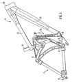
- Fig. 1 shows an embodiment of the invention.
- the suspension system depicted generally comprises a chassis member or frame 2, a rear wheel mounting member 4, an upper linkage 6 and a lower linkage 8.
- the chassis 2 is of relatively conventional construction with a seat support tube 10 (the seat being omitted for clarity) extending at a small rearward angle to the horizontal, a forward strut 12 extending at approximately right angles to the seat tube and a diagonal strut 14 joining the two to form a triangular shape.
- a tube 17 at the front receives the handlebar shaft.
- the pedals and pedal sprocket (not shown) are mounted on an axle extending through the base of the chassis in the conventional manner.
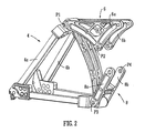
- the rear wheel mounting member and upper and lower linkages can be seen in more detail in Fig. 2 .
- the rear wheel mounting member 4 comprises two almost identical, parallel, approximately triangular, frame-like portions 4a, 4b.
- the frame-like portions 4a, 4b are joined together at two vertex regions which define respective upper and lower pivot supports. These pivot supports support pivot axles P1, P3 of the upper and lower linkages 6, 8 respectively.
- the two frame-like portions provide the mounting for the rear wheel (not shown) which is located between them.
- the upper and lower linkages 6, 8 also comprise respective parallel plates 6a, 6b, 8a, 8b.
- the plates of the upper linkage 6a, 6b are joined by two pivot axles P1, P2.
- the plates of the lower linkage 8a, 8b are joined by two pivot axles P3, P4.
- pivots P1 and P3 couple the upper and lower linkages 6, 8 respectively to the rear wheel mounting member 4.
- the other pivots P2, P4 couple the linkages 6, 8 to the seat tube 10 of the chassis 2.
- a four bar linkage is thereby formed which allows the rear wheel to move relative to the main chassis 2 by compressing and extending the coil spring in the shock absorber 15.
- the upper linkage 6 extends beyond the second pivot axle P2 to pivotally attach to the upper end of a shock absorber 15, the lower end of which is mounted to the lower part of the chassis 2 above the pedal (see Fig. 1 ).
- a further plate 16 is mounted to rotate about the pedal axis and provides a mounting for the jockey wheel which is described below with reference to Fig. 7 .
- both the length of the upper linkage 4 between its pivot points P1, P2; and the length of the lower linkage 6 between its pivot points P3, P4 are greater than the separation between the pivot points P2, P4 at which the linkages are mounted the chassis 2. It will further be observed that the length of the upper linkage (P1 to P2) is greater than that of the lower linkage (P3 to P4). The advantages of these relative dimensions are described below.
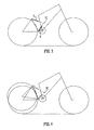
- Fig. 3 shows a simplified schematic diagram of the suspension arrangement described above.
- the axes of the two linkages 6, 8 are shown.
- the axis of a linkage member is defined as the line passing through its two pivot points. If these two axes are extrapolated the point at which they cross is known as the virtual pivot point or instant centre, IC.
- Fig. 3 shows the position of the IC when the cycle is on level ground and
- Fig. 4 shows the position of the IC when uneven ground is encountered and the suspension is mid-way through its travel.
- Fig. 5 shows the full instant centre migration curve throughout the whole of the suspension travel.
- Fig 6 The path of the front and rear wheel axles is shown by Fig 6 . It can be seen that the rear wheel moves along a similarly translated path to the front wheel. A near constant wheelbase is maintained and the wheel moves in a direction that is coherent to the forces transmitted through it by undulations in the terrain.
- the virtual pivot point can be located behind the front axle and above the front sprocket on the vehicle throughout the range of suspension movement as depicted by Fig. 5 .
- the instant centre migration path is very small compared with many other four bar linkage layouts.
- the constant anti-squat curve allows the suspension to remain active when the suspension is subjected to braking forces. It is the relative positions of the pivot points within a certain area that controls the instant centre migration and the rear wheel path.
- certain other four bar linkage designs have attained a rearwards moving wheel path for the rear suspension, the Applicant is not aware of any others that attain both a rear moving wheel path and confine the instant centre migration curve to such a small area and desired location.
- Fig. 7 shows schematically the positioning of a jockey wheel 18 mounted on the bracket 16 ( Fig. 1 ) on the chain drive so that the tensioned section of the chain 20 lies on a line that passes through the instant centre at the mid-travel position.
- the use of the jockey wheel creates minimal chain elongation with suspension movements reducing pedal kickback to just a few degrees of crank movement.
- the main advantage of the embodiment of the invention described above is the ability to control the movement of the instant centre throughout the suspension travel to a minimal migration.
- Use of the jockey wheel means that there is a reduction in growth of the tensioned length of chain. This brings many desirable handling attributes that have been mentioned already.
- the chain device positioned to carry the chain drive on a path directly to the instant centre further increases pedal efficiency.
- Maintaining a constant wheel base allows the front and rear suspension to work in parallel as one cohesive unit rather than two separate entities, giving the vehicle a more stable and predictable handling characteristic.
Landscapes
- Engineering & Computer Science (AREA)
- Mechanical Engineering (AREA)
- Axle Suspensions And Sidecars For Cycles (AREA)
- Automatic Cycles, And Cycles In General (AREA)
Claims (13)
- Aufhängungssystem für ein Fahrrad mit einem Hinterrad-Befestigungselement (4), einem Fahrgestell- bzw. Chassiselement (2), ein an der Chassis (2) befestigtes Spannrad (18), das bei Gebrauch auf die Kette (20) wirkt, eine obere Anlenkung (6), die mit dem Hinterrad-Befestigungselement und dem Chassiselement an einem ersten (P1) bzw. an einem zweiten (P2) Drehpunkt dreh- bzw. schwenkbar befestigt ist, und mit einer unteren Anlenkung (8), die mit dem Hinterrad-Befestigungselement bzw. dem Chassiselement an einem dritten (P3) bzw. an einem vierten (P4) Drehpunkt dreh- bzw. schwenkbar verbunden ist, wodurch ein vierstangiges Anlenksystem gebildet wird, bei dem die Länge der oberen Anlenkung (6) zwischen dem ersten und zweiten Drehpunkt und die Länge der unteren Anlenkung (8) zwischen dem dritten und dem vierten Drehpunkt beide größer sind als die Trennung zwischen dem zweiten und vierten Drehpunkt, gekennzeichnet dadurch, dass die obere Anlenkung (6) länger ist als die untere Anlenkung (8).
- Aufhängungssystem nach Anspruch 1, bei dem die Trennung des ersten (P1) und dritten (P3) Drehpunkts auf dem Hinterrad-Befestigungselement (4) größer ist als die Längen sowohl der oberen (6) als auch der unteren (8) Anlenkung.
- Aufhängungssystem nach Anspruch 1, bei dem die Trennung des ersten und des dritten Drehpunkts auf dem Hinterrad-Befestigungselement größer ist als die Längen sowohl der oberen als auch der unteren Anlenkung, und bei dem das Hinterrad-Befestigungselement im Wesentlichen dreieckig bzw. dreiseitig ist.
- Aufhängungssystem nach einem der vorhergehenden Ansprüche, bei dem das Spannrad (18) derart angeordnet ist, dass es für einen gespannten Abschnitt der Kette (20) sorgt, der durch den momentanen Mittel- bzw. Schwerpunkt bzw. das momentane Zentrum (IC) verläuft.
- Aufhängungssystem nach einem der Ansprüche 1 bis 3, bei dem das Spannrad (18) derart positioniert ist, dass es für einen gespannten Abschnitt der Kette (20) sorgt, der auf einer Linie liegt, die durch das momentane Zentrum (IC) verläuft.
- Aufhängungssystem nach Anspruch 4 oder 5, bei dem der gespannte Abschnitt der Kette (20) oder die Linie durch das momentane Zentrum (IC) verläuft, wenn die Aufhängung zwischen einem Viertel und der Hälfte ihres Arbeitsweges liegt.
- Aufhängungssystem nach Anspruch 4 oder 5, bei dem der gespannte Abschnitt der Kette (20) oder die Linie durch das momentane Zentrum (IC) verläuft, wenn die Aufhängung ungefähr bei einem Drittel des Weges durch ihren Arbeitsweg liegt.
- Aufhängungssystem nach Anspruch 4 oder 5, bei dem der gespannte Abschnitt der Kette (20) oder die Linie durch das momentane Zentrum (IC) verläuft, wenn die Aufhängung in der Hälfte ihres Arbeitsweges liegt.
- Aufhängsungssystem nach einem der vorhergehenden Ansprüche, bei dem die obere (6) und/oder die untere (8) Anlenkung ein Paar paralleler Lamellen bzw. Blechstreifen (6a, 6b, 8a, 8b) aufweist.
- Aufhängungssystem nach einem der vorhergehenden Ansprüche, bei dem das Hinterrad-Befestigungselement im Wesentlichen dreieckig bzw. dreiseitig ist.
- Aufhängungssystem nach Anspruch 10, bei dem der erste (P1) und der dritte (P3) Drehpunkt ungefähr an zwei Scheitelpunkten des Hinterrad-Befestigungselements (4) angeordnet sind und dieses Element eingerichtet ist, um ein Hinterrad an dem dritten Scheitelpunkt aufzunehmen.
- Aufhängungssystem nach einem der vorhergehenden Ansprüche, bei dem das momentane Zentrum (IC) hinter der Vorderradachse und oberhalb des vorderen Zahnkranzes über den gesamten Bereich der Bewegung der Aufhängung hinweg angeordnet ist.
- Fahrrad mit einem Aufhängungssystem gemäß einem der vorhergehenden Ansprüche.
Applications Claiming Priority (2)
| Application Number | Priority Date | Filing Date | Title |
|---|---|---|---|
| GBGB0617086.4A GB0617086D0 (en) | 2006-08-30 | 2006-08-30 | Bicycle suspension |
| PCT/GB2007/003183 WO2008025950A1 (en) | 2006-08-30 | 2007-08-21 | Bicycle suspension |
Publications (2)
| Publication Number | Publication Date |
|---|---|
| EP2061693A1 EP2061693A1 (de) | 2009-05-27 |
| EP2061693B1 true EP2061693B1 (de) | 2010-05-26 |
Family
ID=37137046
Family Applications (1)
| Application Number | Title | Priority Date | Filing Date |
|---|---|---|---|
| EP07789280A Not-in-force EP2061693B1 (de) | 2006-08-30 | 2007-08-21 | Fahrradaufhängung |
Country Status (8)
| Country | Link |
|---|---|
| US (1) | US7938424B2 (de) |
| EP (1) | EP2061693B1 (de) |
| AT (1) | ATE469021T1 (de) |
| CA (1) | CA2662204A1 (de) |
| DE (1) | DE602007006820D1 (de) |
| ES (1) | ES2346811T3 (de) |
| GB (1) | GB0617086D0 (de) |
| WO (1) | WO2008025950A1 (de) |
Families Citing this family (32)
| Publication number | Priority date | Publication date | Assignee | Title |
|---|---|---|---|---|
| EP1799534B1 (de) | 2004-09-15 | 2014-08-27 | Yeti Cycling LLC | Hinterradaufhängungssystem für ein fahrrad |
| US20110187078A1 (en) * | 2010-02-02 | 2011-08-04 | Mark Antony Higgon | Rear suspension unit for after market use in folding bikes |
| GB2482159A (en) * | 2010-07-21 | 2012-01-25 | Atb Sales Ltd | Bicycle rear suspension |
| EP2420435B1 (de) | 2010-08-16 | 2013-10-30 | Andy Wuthrich | Fahrradrahmen mit hinterem Dämpfungssystem |
| US9821879B2 (en) | 2010-08-20 | 2017-11-21 | Yeti Cycling, Llc | Reciprocating rail movement suspension system |
| EP2605953B1 (de) | 2010-08-20 | 2021-06-16 | Yeti Cycling LLC | Bindeglied-aufhängungssystem |
| US9216791B2 (en) * | 2011-03-14 | 2015-12-22 | Christopher Hudec | Bicycle suspension system |
| AU2012228895B2 (en) | 2011-03-14 | 2017-02-23 | Cmh Plus Holdings Ltd. | Bicycle suspension system |
| JP5997592B2 (ja) | 2012-04-27 | 2016-09-28 | 株式会社Nttドコモ | 音声復号装置 |
| US9061729B2 (en) | 2012-08-09 | 2015-06-23 | Christopher Canfield | Suspension system for wheeled vehicles |
| DE102012017647A1 (de) * | 2012-09-06 | 2014-05-15 | Winora-Staiger Gmbh | Fahrrad, insbesondere Mountainbike, mit einem elektrischen Antrieb |
| KR101445667B1 (ko) | 2012-11-29 | 2014-10-01 | 윤종권 | 자전거용 안티 다이브 서스펜션 포크 |
| US10766563B2 (en) | 2013-01-16 | 2020-09-08 | Yeti Cyclying, Llc | Rail suspension with integral shock and dampening mechanism |
| US9242693B2 (en) * | 2013-03-15 | 2016-01-26 | Darrell W. Voss | Bicycle rear suspension |
| US9156521B2 (en) | 2013-12-23 | 2015-10-13 | Wayne Lumpkin | Bicycle frame rear suspension with flexing frame segment |
| FR3021620B1 (fr) * | 2014-05-28 | 2018-10-05 | Caminade | Suspension pour vehicule a 2 roues a transmission par chaine |
| US10737742B2 (en) | 2015-11-24 | 2020-08-11 | Eminent Cycles, LLC | Four bar rear suspension for a bicycle |
| DE102016205540B3 (de) * | 2016-04-04 | 2017-09-28 | QCS Quality Consult Service GmbH | Antriebsvorrichtung für ein elektromotorisch betriebenes fahrrad |
| US10377442B2 (en) * | 2016-11-28 | 2019-08-13 | Brent Neilson | Suspension for a bicycle |
| US11173983B2 (en) | 2017-03-17 | 2021-11-16 | Yeti Cycling, Llc | Vehicle suspension linkage |
| US10457349B2 (en) * | 2017-03-23 | 2019-10-29 | Darrell W. Voss | Vehicle component |
| US11548587B2 (en) | 2017-03-23 | 2023-01-10 | Darrell W Voss | Vehicle |
| US10618595B2 (en) | 2017-03-23 | 2020-04-14 | Darrell W Voss | Vehicle |
| US10723410B2 (en) | 2017-03-23 | 2020-07-28 | Darrell W Voss | Vehicle |
| WO2019010394A1 (en) | 2017-07-07 | 2019-01-10 | Yeti Cycling, Llc | VEHICLE SUSPENSION LINK |
| TWI636911B (zh) * | 2017-08-17 | 2018-10-01 | 巨大機械工業股份有限公司 | 自行車用車架 |
| US10604207B2 (en) * | 2018-02-12 | 2020-03-31 | Carl Winefordner | System and method for adjusting spring rate of a coil spring in a bike suspension |
| US10611428B2 (en) * | 2018-02-12 | 2020-04-07 | Carl Winefordner | System and method for adjusting spring rate of a coil spring in a bike suspension |
| CA3015256A1 (en) * | 2018-08-24 | 2020-02-24 | Clark A. Wallace | Bicycle frame assembly |
| WO2020107055A1 (en) * | 2018-11-29 | 2020-06-04 | Phillip Hoskins | Bicycle linkage |
| US20200247500A1 (en) * | 2019-02-01 | 2020-08-06 | Yeti Cycling, Llc | Multi-body vehicle suspension linkage |
| US20210269117A1 (en) * | 2020-02-28 | 2021-09-02 | Yeti Cycling, Llc | 6-bar vehicle suspension linkage with drive train idler |
Family Cites Families (16)
| Publication number | Priority date | Publication date | Assignee | Title |
|---|---|---|---|---|
| US5413368A (en) * | 1993-09-16 | 1995-05-09 | Cannondale Corporation | Bicycle with trailing arm wheel suspensions |
| US5452910A (en) * | 1994-09-09 | 1995-09-26 | Rockshox, Inc. | Rear wheel suspension for a bicycle and bicycle equipped therewith |
| US20010015540A1 (en) * | 1996-03-15 | 2001-08-23 | Lawwill Merton R. | Rear suspension for a bicycle |
| FR2750668B1 (fr) * | 1996-07-03 | 1998-11-20 | Savard Franck | Dispositif de tension et de guidage d'une chaine pour un changement de vitesses de velo |
| DE19726067B4 (de) * | 1997-06-19 | 2006-04-20 | Hawk Bikes Entwicklung & Marketing Gmbh | Zweirad, insbesondere Fahrrad mit Antriebsmittelumlenkung |
| DE69932323T2 (de) | 1998-03-02 | 2006-11-23 | Anthony S. Ramona Ellsworth | Fahrradaufhängungsvorrichtung und entsprechendes verfahren |
| FR2789360A1 (fr) | 1999-02-05 | 2000-08-11 | Jean Pierre Fournales | VEHICULE A ROUES DONT l'AXE DE LA ROUE MOTRICE EST PORTE PAR UN BRAS OSCILLANT ET DONT LE COUPLE MOTEUR EST TRANSMIS A LA ROUE MOTRICE PAR CHAINE ET PIGNONS |
| US6283487B1 (en) * | 2000-04-25 | 2001-09-04 | Robert Torre | Parallelogram bicycle suspension system |
| US6843494B2 (en) * | 2001-08-22 | 2005-01-18 | Rocky Mountain Bicycles | Rear suspension system for two-wheeled vehicles, particularly bicycles |
| CA2357167A1 (en) * | 2001-09-11 | 2003-03-11 | Jonathan Duval | A rear wheel suspension for a bicycle |
| EP1572524B1 (de) * | 2002-11-21 | 2008-08-20 | Toptrail Limited | Aufhängungssysteme |
| US6880847B2 (en) * | 2003-05-27 | 2005-04-19 | Specialized Bicycle Components, Inc. | Bicycle rear suspension |
| US7467803B2 (en) * | 2003-12-12 | 2008-12-23 | Noel Buckley | Rear suspension system for bicycles |
| US20060033306A1 (en) * | 2004-08-11 | 2006-02-16 | Sanchez Steve E | Multi-bar linkage suspension system |
| US7377535B2 (en) | 2004-10-29 | 2008-05-27 | Specialized Bicycle Components, Inc. | Bicycle frame |
| US20050253357A1 (en) * | 2005-08-18 | 2005-11-17 | Owen Chang | Bicycle with suspension |
-
2006
- 2006-08-30 GB GBGB0617086.4A patent/GB0617086D0/en not_active Ceased
-
2007
- 2007-08-21 DE DE602007006820T patent/DE602007006820D1/de active Active
- 2007-08-21 AT AT07789280T patent/ATE469021T1/de not_active IP Right Cessation
- 2007-08-21 ES ES07789280T patent/ES2346811T3/es active Active
- 2007-08-21 WO PCT/GB2007/003183 patent/WO2008025950A1/en active Application Filing
- 2007-08-21 EP EP07789280A patent/EP2061693B1/de not_active Not-in-force
- 2007-08-21 US US12/439,194 patent/US7938424B2/en not_active Expired - Fee Related
- 2007-08-21 CA CA002662204A patent/CA2662204A1/en not_active Abandoned
Also Published As
| Publication number | Publication date |
|---|---|
| WO2008025950A1 (en) | 2008-03-06 |
| ATE469021T1 (de) | 2010-06-15 |
| DE602007006820D1 (de) | 2010-07-08 |
| GB0617086D0 (en) | 2006-10-11 |
| US20090322055A1 (en) | 2009-12-31 |
| US7938424B2 (en) | 2011-05-10 |
| EP2061693A1 (de) | 2009-05-27 |
| CA2662204A1 (en) | 2008-03-06 |
| ES2346811T3 (es) | 2010-10-20 |
Similar Documents
| Publication | Publication Date | Title |
|---|---|---|
| EP2061693B1 (de) | Fahrradaufhängung | |
| US8857842B2 (en) | Bicycle rear suspension | |
| US7427077B2 (en) | Rear suspension of a two-wheel vehicle or the like | |
| US6843494B2 (en) | Rear suspension system for two-wheeled vehicles, particularly bicycles | |
| EP2420435B1 (de) | Fahrradrahmen mit hinterem Dämpfungssystem | |
| EP1698549B1 (de) | Fahrrad mit Hinteraufhängung | |
| EP0966384B1 (de) | Fahrradaufhängungsvorrichtung | |
| EP2886436B1 (de) | Schneemobil | |
| EP3261908B1 (de) | Hinteres federungssystem für ein fahrrad | |
| AU2010360170B2 (en) | Rear wheel suspension for a vehicle, in particular a bicycle | |
| US8672076B2 (en) | Motorcycle rear-wheels transmission and suspension system | |
| US7556276B1 (en) | Bicycle rear wheel suspension chassis | |
| US20110291382A1 (en) | Rear suspension for a two-wheel vehicle | |
| GB2525870A (en) | Rear suspension system for velocipedes | |
| JP2004352209A (ja) | スイングアーム式懸架装置 |
Legal Events
| Date | Code | Title | Description |
|---|---|---|---|
| PUAI | Public reference made under article 153(3) epc to a published international application that has entered the european phase |
Free format text: ORIGINAL CODE: 0009012 |
|
| 17P | Request for examination filed |
Effective date: 20090327 |
|
| AK | Designated contracting states |
Kind code of ref document: A1 Designated state(s): AT BE BG CH CY CZ DE DK EE ES FI FR GB GR HU IE IS IT LI LT LU LV MC MT NL PL PT RO SE SI SK TR |
|
| AX | Request for extension of the european patent |
Extension state: AL BA HR MK RS |
|
| 17Q | First examination report despatched |
Effective date: 20090625 |
|
| GRAP | Despatch of communication of intention to grant a patent |
Free format text: ORIGINAL CODE: EPIDOSNIGR1 |
|
| DAX | Request for extension of the european patent (deleted) | ||
| GRAS | Grant fee paid |
Free format text: ORIGINAL CODE: EPIDOSNIGR3 |
|
| GRAA | (expected) grant |
Free format text: ORIGINAL CODE: 0009210 |
|
| AK | Designated contracting states |
Kind code of ref document: B1 Designated state(s): AT BE BG CH CY CZ DE DK EE ES FI FR GB GR HU IE IS IT LI LT LU LV MC MT NL PL PT RO SE SI SK TR |
|
| REG | Reference to a national code |
Ref country code: GB Ref legal event code: FG4D |
|
| REG | Reference to a national code |
Ref country code: CH Ref legal event code: EP |
|
| REG | Reference to a national code |
Ref country code: IE Ref legal event code: FG4D |
|
| REF | Corresponds to: |
Ref document number: 602007006820 Country of ref document: DE Date of ref document: 20100708 Kind code of ref document: P |
|
| REG | Reference to a national code |
Ref country code: NL Ref legal event code: T3 Ref country code: NL Ref legal event code: VDEP Effective date: 20100526 |
|
| REG | Reference to a national code |
Ref country code: ES Ref legal event code: FG2A Ref document number: 2346811 Country of ref document: ES Kind code of ref document: T3 |
|
| LTIE | Lt: invalidation of european patent or patent extension |
Effective date: 20100526 |
|
| PG25 | Lapsed in a contracting state [announced via postgrant information from national office to epo] |
Ref country code: SE Free format text: LAPSE BECAUSE OF FAILURE TO SUBMIT A TRANSLATION OF THE DESCRIPTION OR TO PAY THE FEE WITHIN THE PRESCRIBED TIME-LIMIT Effective date: 20100526 Ref country code: LT Free format text: LAPSE BECAUSE OF FAILURE TO SUBMIT A TRANSLATION OF THE DESCRIPTION OR TO PAY THE FEE WITHIN THE PRESCRIBED TIME-LIMIT Effective date: 20100526 |
|
| PG25 | Lapsed in a contracting state [announced via postgrant information from national office to epo] |
Ref country code: AT Free format text: LAPSE BECAUSE OF FAILURE TO SUBMIT A TRANSLATION OF THE DESCRIPTION OR TO PAY THE FEE WITHIN THE PRESCRIBED TIME-LIMIT Effective date: 20100526 Ref country code: FI Free format text: LAPSE BECAUSE OF FAILURE TO SUBMIT A TRANSLATION OF THE DESCRIPTION OR TO PAY THE FEE WITHIN THE PRESCRIBED TIME-LIMIT Effective date: 20100526 Ref country code: SI Free format text: LAPSE BECAUSE OF FAILURE TO SUBMIT A TRANSLATION OF THE DESCRIPTION OR TO PAY THE FEE WITHIN THE PRESCRIBED TIME-LIMIT Effective date: 20100526 Ref country code: LV Free format text: LAPSE BECAUSE OF FAILURE TO SUBMIT A TRANSLATION OF THE DESCRIPTION OR TO PAY THE FEE WITHIN THE PRESCRIBED TIME-LIMIT Effective date: 20100526 Ref country code: IS Free format text: LAPSE BECAUSE OF FAILURE TO SUBMIT A TRANSLATION OF THE DESCRIPTION OR TO PAY THE FEE WITHIN THE PRESCRIBED TIME-LIMIT Effective date: 20100926 |
|
| PG25 | Lapsed in a contracting state [announced via postgrant information from national office to epo] |
Ref country code: PL Free format text: LAPSE BECAUSE OF FAILURE TO SUBMIT A TRANSLATION OF THE DESCRIPTION OR TO PAY THE FEE WITHIN THE PRESCRIBED TIME-LIMIT Effective date: 20100526 Ref country code: CY Free format text: LAPSE BECAUSE OF FAILURE TO SUBMIT A TRANSLATION OF THE DESCRIPTION OR TO PAY THE FEE WITHIN THE PRESCRIBED TIME-LIMIT Effective date: 20100609 |
|
| PG25 | Lapsed in a contracting state [announced via postgrant information from national office to epo] |
Ref country code: PT Free format text: LAPSE BECAUSE OF FAILURE TO SUBMIT A TRANSLATION OF THE DESCRIPTION OR TO PAY THE FEE WITHIN THE PRESCRIBED TIME-LIMIT Effective date: 20100927 Ref country code: NL Free format text: LAPSE BECAUSE OF FAILURE TO SUBMIT A TRANSLATION OF THE DESCRIPTION OR TO PAY THE FEE WITHIN THE PRESCRIBED TIME-LIMIT Effective date: 20100526 Ref country code: EE Free format text: LAPSE BECAUSE OF FAILURE TO SUBMIT A TRANSLATION OF THE DESCRIPTION OR TO PAY THE FEE WITHIN THE PRESCRIBED TIME-LIMIT Effective date: 20100526 Ref country code: DK Free format text: LAPSE BECAUSE OF FAILURE TO SUBMIT A TRANSLATION OF THE DESCRIPTION OR TO PAY THE FEE WITHIN THE PRESCRIBED TIME-LIMIT Effective date: 20100526 |
|
| PG25 | Lapsed in a contracting state [announced via postgrant information from national office to epo] |
Ref country code: SK Free format text: LAPSE BECAUSE OF FAILURE TO SUBMIT A TRANSLATION OF THE DESCRIPTION OR TO PAY THE FEE WITHIN THE PRESCRIBED TIME-LIMIT Effective date: 20100526 Ref country code: BE Free format text: LAPSE BECAUSE OF FAILURE TO SUBMIT A TRANSLATION OF THE DESCRIPTION OR TO PAY THE FEE WITHIN THE PRESCRIBED TIME-LIMIT Effective date: 20100526 Ref country code: CZ Free format text: LAPSE BECAUSE OF FAILURE TO SUBMIT A TRANSLATION OF THE DESCRIPTION OR TO PAY THE FEE WITHIN THE PRESCRIBED TIME-LIMIT Effective date: 20100526 Ref country code: RO Free format text: LAPSE BECAUSE OF FAILURE TO SUBMIT A TRANSLATION OF THE DESCRIPTION OR TO PAY THE FEE WITHIN THE PRESCRIBED TIME-LIMIT Effective date: 20100526 |
|
| PG25 | Lapsed in a contracting state [announced via postgrant information from national office to epo] |
Ref country code: MC Free format text: LAPSE BECAUSE OF NON-PAYMENT OF DUE FEES Effective date: 20100831 |
|
| PLBE | No opposition filed within time limit |
Free format text: ORIGINAL CODE: 0009261 |
|
| STAA | Information on the status of an ep patent application or granted ep patent |
Free format text: STATUS: NO OPPOSITION FILED WITHIN TIME LIMIT |
|
| 26N | No opposition filed |
Effective date: 20110301 |
|
| PG25 | Lapsed in a contracting state [announced via postgrant information from national office to epo] |
Ref country code: GR Free format text: LAPSE BECAUSE OF FAILURE TO SUBMIT A TRANSLATION OF THE DESCRIPTION OR TO PAY THE FEE WITHIN THE PRESCRIBED TIME-LIMIT Effective date: 20100827 |
|
| REG | Reference to a national code |
Ref country code: DE Ref legal event code: R097 Ref document number: 602007006820 Country of ref document: DE Effective date: 20110228 |
|
| PG25 | Lapsed in a contracting state [announced via postgrant information from national office to epo] |
Ref country code: IE Free format text: LAPSE BECAUSE OF NON-PAYMENT OF DUE FEES Effective date: 20100821 |
|
| PGFP | Annual fee paid to national office [announced via postgrant information from national office to epo] |
Ref country code: DE Payment date: 20110825 Year of fee payment: 5 Ref country code: ES Payment date: 20110829 Year of fee payment: 5 Ref country code: FR Payment date: 20110905 Year of fee payment: 5 Ref country code: GB Payment date: 20110822 Year of fee payment: 5 |
|
| PG25 | Lapsed in a contracting state [announced via postgrant information from national office to epo] |
Ref country code: MT Free format text: LAPSE BECAUSE OF FAILURE TO SUBMIT A TRANSLATION OF THE DESCRIPTION OR TO PAY THE FEE WITHIN THE PRESCRIBED TIME-LIMIT Effective date: 20100526 |
|
| PGFP | Annual fee paid to national office [announced via postgrant information from national office to epo] |
Ref country code: NL Payment date: 20110831 Year of fee payment: 5 Ref country code: IT Payment date: 20110825 Year of fee payment: 5 |
|
| REG | Reference to a national code |
Ref country code: CH Ref legal event code: PL |
|
| PG25 | Lapsed in a contracting state [announced via postgrant information from national office to epo] |
Ref country code: LI Free format text: LAPSE BECAUSE OF NON-PAYMENT OF DUE FEES Effective date: 20110831 Ref country code: CH Free format text: LAPSE BECAUSE OF NON-PAYMENT OF DUE FEES Effective date: 20110831 |
|
| PG25 | Lapsed in a contracting state [announced via postgrant information from national office to epo] |
Ref country code: BG Free format text: LAPSE BECAUSE OF FAILURE TO SUBMIT A TRANSLATION OF THE DESCRIPTION OR TO PAY THE FEE WITHIN THE PRESCRIBED TIME-LIMIT Effective date: 20100526 Ref country code: LU Free format text: LAPSE BECAUSE OF NON-PAYMENT OF DUE FEES Effective date: 20100821 Ref country code: HU Free format text: LAPSE BECAUSE OF FAILURE TO SUBMIT A TRANSLATION OF THE DESCRIPTION OR TO PAY THE FEE WITHIN THE PRESCRIBED TIME-LIMIT Effective date: 20101127 |
|
| PG25 | Lapsed in a contracting state [announced via postgrant information from national office to epo] |
Ref country code: TR Free format text: LAPSE BECAUSE OF FAILURE TO SUBMIT A TRANSLATION OF THE DESCRIPTION OR TO PAY THE FEE WITHIN THE PRESCRIBED TIME-LIMIT Effective date: 20100526 |
|
| REG | Reference to a national code |
Ref country code: NL Ref legal event code: V1 Effective date: 20130301 |
|
| GBPC | Gb: european patent ceased through non-payment of renewal fee |
Effective date: 20120821 |
|
| PG25 | Lapsed in a contracting state [announced via postgrant information from national office to epo] |
Ref country code: NL Free format text: LAPSE BECAUSE OF FAILURE TO SUBMIT A TRANSLATION OF THE DESCRIPTION OR TO PAY THE FEE WITHIN THE PRESCRIBED TIME-LIMIT Effective date: 20130301 |
|
| REG | Reference to a national code |
Ref country code: FR Ref legal event code: ST Effective date: 20130430 |
|
| PG25 | Lapsed in a contracting state [announced via postgrant information from national office to epo] |
Ref country code: IT Free format text: LAPSE BECAUSE OF NON-PAYMENT OF DUE FEES Effective date: 20120821 |
|
| PG25 | Lapsed in a contracting state [announced via postgrant information from national office to epo] |
Ref country code: DE Free format text: LAPSE BECAUSE OF NON-PAYMENT OF DUE FEES Effective date: 20130301 Ref country code: GB Free format text: LAPSE BECAUSE OF NON-PAYMENT OF DUE FEES Effective date: 20120821 |
|
| PG25 | Lapsed in a contracting state [announced via postgrant information from national office to epo] |
Ref country code: FR Free format text: LAPSE BECAUSE OF NON-PAYMENT OF DUE FEES Effective date: 20120831 |
|
| REG | Reference to a national code |
Ref country code: DE Ref legal event code: R119 Ref document number: 602007006820 Country of ref document: DE Effective date: 20130301 |
|
| PG25 | Lapsed in a contracting state [announced via postgrant information from national office to epo] |
Ref country code: BG Free format text: LAPSE BECAUSE OF FAILURE TO SUBMIT A TRANSLATION OF THE DESCRIPTION OR TO PAY THE FEE WITHIN THE PRESCRIBED TIME-LIMIT Effective date: 20100826 |
|
| REG | Reference to a national code |
Ref country code: ES Ref legal event code: FD2A Effective date: 20131018 |
|
| PG25 | Lapsed in a contracting state [announced via postgrant information from national office to epo] |
Ref country code: ES Free format text: LAPSE BECAUSE OF NON-PAYMENT OF DUE FEES Effective date: 20120822 |