EP2061369B1 - Vorrichtung zum erfassen der lese-sehschärfe - Google Patents
Vorrichtung zum erfassen der lese-sehschärfe Download PDFInfo
- Publication number
- EP2061369B1 EP2061369B1 EP07815184A EP07815184A EP2061369B1 EP 2061369 B1 EP2061369 B1 EP 2061369B1 EP 07815184 A EP07815184 A EP 07815184A EP 07815184 A EP07815184 A EP 07815184A EP 2061369 B1 EP2061369 B1 EP 2061369B1
- Authority
- EP
- European Patent Office
- Prior art keywords
- reading
- test person
- distance
- graphics
- texts
- Prior art date
- Legal status (The legal status is an assumption and is not a legal conclusion. Google has not performed a legal analysis and makes no representation as to the accuracy of the status listed.)
- Not-in-force
Links
- 238000012360 testing method Methods 0.000 claims abstract description 33
- 238000000034 method Methods 0.000 claims description 28
- 230000008569 process Effects 0.000 claims description 20
- 208000001491 myopia Diseases 0.000 claims description 12
- 238000005286 illumination Methods 0.000 claims description 10
- 238000007639 printing Methods 0.000 claims description 2
- 230000004304 visual acuity Effects 0.000 abstract description 11
- 230000004313 glare Effects 0.000 abstract description 10
- 230000003203 everyday effect Effects 0.000 abstract 1
- 238000005375 photometry Methods 0.000 abstract 1
- 238000005259 measurement Methods 0.000 description 17
- 101100310948 Caenorhabditis elegans srd-1 gene Proteins 0.000 description 16
- 101100310954 Caenorhabditis elegans srd-2 gene Proteins 0.000 description 11
- 238000010586 diagram Methods 0.000 description 9
- 230000004438 eyesight Effects 0.000 description 6
- 230000003287 optical effect Effects 0.000 description 4
- 230000008859 change Effects 0.000 description 3
- 210000003128 head Anatomy 0.000 description 3
- 238000011835 investigation Methods 0.000 description 3
- 230000003213 activating effect Effects 0.000 description 2
- 239000003086 colorant Substances 0.000 description 2
- 238000010276 construction Methods 0.000 description 2
- 230000006870 function Effects 0.000 description 2
- 238000003825 pressing Methods 0.000 description 2
- 238000012800 visualization Methods 0.000 description 2
- 208000032041 Hearing impaired Diseases 0.000 description 1
- 238000002679 ablation Methods 0.000 description 1
- 238000004458 analytical method Methods 0.000 description 1
- 238000013459 approach Methods 0.000 description 1
- 238000004364 calculation method Methods 0.000 description 1
- 238000004891 communication Methods 0.000 description 1
- 230000000052 comparative effect Effects 0.000 description 1
- 238000012790 confirmation Methods 0.000 description 1
- 238000012937 correction Methods 0.000 description 1
- 238000001514 detection method Methods 0.000 description 1
- 238000005516 engineering process Methods 0.000 description 1
- 238000011156 evaluation Methods 0.000 description 1
- 239000003292 glue Substances 0.000 description 1
- 238000003384 imaging method Methods 0.000 description 1
- 239000003550 marker Substances 0.000 description 1
- 239000000463 material Substances 0.000 description 1
- 201000010041 presbyopia Diseases 0.000 description 1
- 238000013102 re-test Methods 0.000 description 1
- 230000011514 reflex Effects 0.000 description 1
- 230000029058 respiratory gaseous exchange Effects 0.000 description 1
- 230000000284 resting effect Effects 0.000 description 1
- 238000007619 statistical method Methods 0.000 description 1
- 239000013589 supplement Substances 0.000 description 1
- 238000001356 surgical procedure Methods 0.000 description 1
- 230000001360 synchronised effect Effects 0.000 description 1
- 238000012549 training Methods 0.000 description 1
- 238000012546 transfer Methods 0.000 description 1
- 238000002604 ultrasonography Methods 0.000 description 1
Images



Classifications
-
- A—HUMAN NECESSITIES
- A61—MEDICAL OR VETERINARY SCIENCE; HYGIENE
- A61B—DIAGNOSIS; SURGERY; IDENTIFICATION
- A61B3/00—Apparatus for testing the eyes; Instruments for examining the eyes
- A61B3/02—Subjective types, i.e. testing apparatus requiring the active assistance of the patient
- A61B3/028—Subjective types, i.e. testing apparatus requiring the active assistance of the patient for testing visual acuity; for determination of refraction, e.g. phoropters
- A61B3/032—Devices for presenting test symbols or characters, e.g. test chart projectors
Definitions
- the invention relates to a device for detecting the visual acuity (visual acuity) according to the preamble of claim 1, especially when reading texts (near or reading visus, English 'near vision acuity' or 'reading acuity'). Near vision, which is determined in terms of reading text, is also called reading.
- Devices of this type are known in principle.
- the person whose visual acuity is to be determined (the test person / the test person) visually presents a graphic or graphically represented symbols, letters or text and checks whether these or specific features are recognized correctly.
- This regularly more or less standardized graphical symbols or characters are used, in particular Radner reading boards, panels with differently oriented Landolt C symbols or the letter board according to Snellen.
- Devices for aiding the visual acuity determination are, for example, in US 6,422,700 and US 6,663,241 described.
- US 2006/0078858 A1 A method is disclosed for determining the vision of a person in which the person reads a group of words shown to her and determines the reading speed and uses it as the basis of vision determination. A distance between the person and the phrase is measured and taken into account in the visualization.
- US 5,568,209 is an eye test device described in which a certain distance to the panel can be adjusted.
- a device which is used to determine the visual acuity when reading text by a subject, with a presentation surface on which a number of graphics with text different font size is displayed, and a microphone for receiving utterances of the subject when reading the texts is equipped, as well as with a computer device which is adapted to derive from the microphone recordings beginning and end of the reading process and from a distanzkorrig believing Nahvisus or Lesevisus of the subject to determine.
- the stated object is achieved by a device according to claim 1.
- the invention provides a means for measuring the subject freely selectable reading distance of the subject from the displayed text (the illustrated graphic) on the presentation surface (eg, high resolution LCD display or reading boards or graphics), the computing device being adapted to use of the thus measured reading distance to correct the near vision or Lesevisus to a distance-corrected value, preferably using a photogrammetric device as means for measuring the reading distance.
- a reading distance is not predetermined, but the test person can choose this freely and also change during the determination of the visus, without thereby affecting the measuring process. Only because the test person can freely choose the reading distance, also different for different font sizes, a realistic, the true life appropriate measurement of Lesevisus is possible.
- Preferred embodiments of the invention have either a lighting system permanently connected to the presentation surface with at least one illumination means and a light meter for measuring the illumination prevailing in the area of the texts / graphics (in the sense of a luminance or illuminance), and a control circuit for adjusting the light emanating from the illumination means Luminous intensity over the light meter to a desired value of the illumination, with the possibility of using different forms of glare which thereby adjusts itself on the texts / graphics), or a display with a maximum of 0.166 mm point distance with computer-controlled adjustment of luminance, luminance contrast and Color, with the possibility of using different forms of glare.
- the light meter may advantageously be a light sensor located in or on the presentation surface.
- the calculation of the distance corrected reading can be done simply, based on a mathematical relationship (see the equation below) using the reading distance and the logarithm of the font size of a text still readable by the subject. If appropriate, the angle of inclination of the reading material can also be taken into account mathematically.
- the reading process can be made more pleasant for the test person if the presentation surface can be tilted towards the test subject by a pitch axis parallel to the right-and-left axis of the test subject.
- the computer device can additionally be set up to derive from the microphone recordings the beginning and end of the reading process and to calculate therefrom a reading speed depending on the length of the respectively read text.
- the means for measuring the reading distance may advantageously be a photogrammetric device adapted to determine the position of a reference point on the face of the subject, preferably in the area of the eyes, in relation to the position of the presentation area for calculating the reading distance can be set.
- This face eg the root of the nose or the middle bridge of a spectacle frame, can be detected directly or be marked by means of a mark or color spots.
- the mark or color spot may then be e.g. be executed in daylight color and illuminated during the measurement process with suitable UV LEDs.
- the following exemplary embodiment relates to an arrangement SRD-1 or SRD-2, which is also referred to as the Salzburg Reading Desk according to its place of origin and which is used to determine the distance-corrected reading cycle including the photogrammetrically measured average reading distance and simultaneous measurement and logging of the reading speed.
- the reading angle and the standardized illumination, or when using a display with different luminance, luminance contrast and color, with the possibility of using different forms of glare (glare) is used.
- the invention is not limited to this embodiment SRD.
- the arrangement consists of a lectern-like test place, which in Fig.1 1a, and a control computer as a control device, for example by means of a personal computer or laptop computer (reference numeral 15 in FIG Fig. 3 or 3a) realized with suitable control and measurement software.
- reading cards can be offered as incident-light or transmitted-light templates on the display of a test subject.
- Each template has a standardized text with standardized font size and preferably standardized content.
- the subject reads (or tries) the text from the template and, as a result, a (tentative) reading experience is determined.
- the device additionally has a device for determining the reading distance, preferably realized by means of cameras. The reading distance is measured, preferably during the reading process, and a distance-corrected reading period is calculated from the reading distance and the font size of the respective text.
- the device may also include controlled lighting and a microphone that can be used to measure the reading time.
- the Radner reading boards mentioned above are used. Each paragraph of these panels contains a (German) sentence consisting of 14 words arranged on 3 lines. The character sizes of the reading boards are graduated according to a geometric series, with a factor of 10 0.1 . The reading tables are assigned LogRAD values that correspond to the (scaled) logarithm of the character size; The LogRAD values therefore run linearly, for example from 0.9 (largest font) to -0.2 (smallest font) for a reading distance of 40 cm. Further information on the Radner panels can be found in the already mentioned articles by W. Radner et al. and E. Stifter et al. refer to.
- templates may contain appropriate symbols or graphics of various kinds, e.g. Numbers Numbers, e-hooks, Landolt rings, characters of other languages, music notes, maps, city maps, timetables, pictures for children, including the version SRD-2 on the display serving display in different contrast levels or colors can be faded in, with the possibility of using different forms of glare.
- the arrangement SRD-1 comprises a housing 1, the basic construction of which is a horizontal frame 2 divided by a web, on which a hinged flat plate 3 is fixed as a presentation surface which covers approximately half of the housing 1.
- the web is in the center attached a commercial spindle motor 4, with the help of which the subject can adjust the angle of the reading surface between 0 ° and 40 ° itself.
- the spindle motor 4 projects in the embodiment shown down through the support surface addition.
- the reading surface 3 At the rear edge of the reading surface 3 are in the arrangement SRD-1 two commercially available lamps 5 (so-called Reprotypn) that provide a flicker-free lighting (eg with DC or high frequency power supply), here each 18 watts of power and a light color of 5400 K attached.
- the brightness of the lamps 5 on the reading surface is kept constant by means of a measuring head 6 of a lux meter 6a, a control device 6b and the control computer 15 mounted in the reading surface.
- the user sets the desired illuminance, for example 500 lux ( ⁇ 10 lux), on the control computer.
- the light measurement can be carried out by measuring the luminance (in cd / m 2) at the location of the reading panels by means of a sensor (not shown) located above the reading surface 3 and directed onto the reading surface.
- the brightness can also be set with the aid of a dimmer (not shown) instead of the control unit 6a to the respective desired luminance or illuminance.
- a number of reading plates 7, for example the individual paragraphs of the standardized Radner reading plates, are fixed in the arrangement SRD-1, for example by means of a horizontally (from right to left) running ring binder-like attachment 8, which is a turning of the individual Panels downwards (ie towards a smaller font size), each font size being displayed on its own page
- the subject will continue to leaf through the pages during the examination.
- the task of the subject is to read aloud the texts presented on the reading boards one after the other.
- the distance-corrected read vector is calculated from the read character height and the measured average reading distance. In addition, the reading duration is measured.
- This bound with ring back "booklet” is designed so that in the arrangement SRD-1 of the recessed into the reading surface measuring head 6 of the Luxmeters is illuminated exactly in the center of the open booklet of the illumination 5 and so a precise lighting (luminance or illuminance) the reading surface is guaranteed.
- the arrangement SRD-2 comprises a housing 1a, the basic construction of which is a lying frame 2a on which a hinged display 3a is mounted as a presentation surface.
- a light meter 6d resting against the display 3a is provided, which is designed as a light sensor facing the display 3a.
- the display 3a can be controlled with the connected PC 15 luminance, luminance contrast, color and the template change, with the possibility of using different types of glare (glare).
- UV LEDs 16 which illuminate the measuring mark or color spot during the measuring process.
- a microphone 9 which is connected to an acoustic threshold value switch (not shown).
- the microphone is used to record the speech of the subject and thus accurately determine the respective reading duration of the subject. From this, the control / measuring software can calculate the reading speed in words per minute. For this purpose, it is determined by means of this acoustic threshold switch when the subject speaks. A pause in speech that lasts for a long period of time, for example, for a few seconds (because short pauses can be due to pauses in speech such as breathing or voiceless sounds) is interpreted as the end of the reading process.
- a signal button may be provided, with which the subject (eg in the case of a silent or speech-impaired subjects) signals the reading time, for example by pressing the signal button at the beginning and end of reading a text.
- the measuring process can be carried out essentially without a control person, with a view to automating the examination procedure.
- an optical signal (signal lamp) may be provided to indicate in particular a hearing impaired subject the beginning of the measurement process. This optical signal can thus serve as a supplement to the acoustic start signal of the reading process.
- a commercially available inclinometer 10 of known type is mounted on the reading surface, preferably on its underside.
- the angle of the reading surface can also be transmitted to an angle sensor 10a with a flexible shaft 10b.
- two video cameras 11, 11a of high resolution are mounted on a stage.
- the cameras are, for example, AXIS 206M from Axis Communications AB (Sweden) or cameras from "The Imaging Source", USA-DE.
- the reading distance i.e., the distance of a reference point in the subject's face, such as the nose root, or spectacle frame, from the reading boards
- a mark e.g. in the form of a colored glue dot in a daylight color with 12 mm diameter, is glued at the beginning of the investigation on the nose root of the test person or on the center bar of a spectacle frame.
- the video cameras are used to determine the position of the mark, and from this the distance of the mark to the read line is calculated by means of photogrammetry as a function of the set reading angle, taking into account the geometric arrangement of the video cameras (mutual distance, height, orientation).
- the video cameras 11, 11a are located behind the reading table 3, 3a in a well-defined arrangement relative to the presentation surface (in the illustrated embodiment SRD-1 72.7 cm from the front edge of the surface 3 and 51 cm above the base plate, in a mutual Distance of 21 cm) and are aligned so that both capture the space occupied by the head of the subject;
- the main optical axes of the cameras lie in a horizontal plane.
- the spatial coordinates of the mark and, as a consequence, the distance of the mark from the text to be read are calculated from the two camera images.
- the object point which is characterized by the particular color of the mark, is searched in each picture.
- the midpoint of the color range found is used as the result coordinate.
- the position of the marker with respect to the camera positions is determined according to a known stereo image method.
- the invention is not bound to the photogrammetric measurement of the respective, freely selectable by the subject reading distance; rather, it can also be determined in another suitable manner, for example acoustically by means of ultrasound.
- the area of the reading panel 7 or the display 3a can additionally be surrounded by a peep-box-like housing (not shown), which can also be realized as a tunnel-shaped cover.
- a peep-box-like housing (not shown), which can also be realized as a tunnel-shaped cover.
- a data interface 12 is provided which communicates via analog inputs and a USB output to the control computer 15 on which runs the measurement and control software; the data interface 12 is implemented, for example, using a DAQ module USBDAQ-9100MS from Adlink Technology Inc. (Taiwan / USA).
- the necessary power supply units for low-voltage supply (not shown) and the power supply and the connection to the electrical network for the spindle motor 4 or chain thrust drive 4a are housed inside the housing.
- the analogue data of inclinometer, Luxmeter 6a or luminance meter 6c and acoustic threshold value switch are fed in and output via a USB output to the PC.
- an Ethernet switch 13 is installed, which realizes a LAN, via which the two video cameras 11 communicate with the PC, or when using Firewire cameras 11a a Firewire HUB 13a.
- the internals under the reading surface are shielded by a metallic grid. From the test site thus lead away three leads, namely a power cord (eg 230 V) for power supply to the usual power grid, a USB cable and an Ethernet or Firewire connection to the control computer 15.
- a power cord eg 230 V
- the power supply of the individual components and the spindle motor or chain thrust drive 4a are in Fig. 3, 3a not shown.
- All devices are switched on or off with a central power switch 14 from the outside, which is attached for example to the rear of the housing or the side of the housing.
- a central power switch 14 is attached for example to the rear of the housing or the side of the housing.
- an angle of 20 ° is specified as the default setting, wherein in the arrangement SRD-1, the angle depending on the respective reading habit of the subject between 0 ° and 40 °, in the arrangement SRD-2 between 0 ° and 90 ° is freely selectable.
- a measurement and control software controls the course of the visus determination. It is advantageously designed so that the investigator can be guided by a simple keystroke or mouse click through the investigation, on the one hand on any of the necessary inputs can be forgotten and on the other hand, an automatic storage or the expression of the result.
- a step-by-step guidance is issued visually and / or acoustically by the computer for the entire process. As a result, the training time of the operating staff is reduced and, in addition, errors in the course of vision determination are avoided.
- the automatic running examination is made possible without the necessary presence of an investigator.
- the measurement and control software runs on a PC with a screen, mouse and keyboard and is preferably started separately from the device SRD-1, or can run automatically in a further implementation without the necessary presence of an investigator-ladder.
- the software performs the following functions in sequence: checking the integrity of the program file, displaying the preparation window on the screen, reading the device and measurement parameters from a parameter file, starting the image transfer from the two cameras to the PC and displaying as two live video images on the screen (eg as inserts). If the two video images are visible, the investigator or user starts the actual examination process by a specific input, eg with the enter key.
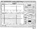
- the program starts immediately with the current measurement of the luminance and the inclination angle; these are displayed in the main window of the ad as in Fig. 4 shown.
- buttons are advantageously designed differently: button with double frame are activated with the Enter key; Buttons with a simple frame can be activated with the mouse or with "hot key”; Buttons with gray text can not be activated.
- This allows standard operation (in the sense of the usual procedure of visualization) with only one key, e.g. the enter key. As a result, the risk of incorrect operation is largely eliminated without restricting flexibility.
- each sentence is reproduced in a certain font height corresponding to the sentence number; By selecting the block number, the font height is thus selected (or vice versa).
- the sound and distance measurement is started with the ⁇ Start> button and subsequently displayed in the main window, as in Fig. 6 shown.
- the program checks the signal at the output of the sound amplifier and displays its status in the time diagram of the SRD window. Subsequently, the respective image coordinates of the center of the color mark are detected in both video images. The color of the color mark must not otherwise occur in the picture. From these image coordinates, the camera distance and the image scale of the cameras, the program calculates in a next step stereophotogrammetrically the spatial coordinates of the position of the color mark. In the following step, the distance of the color mark position from the reading line whose coordinates are known to the program is calculated.
- the result is displayed graphically as a numerical value in its output box and in the distance diagram of the SRD window. This process repeats continuously, for a maximum of 25 seconds, or is terminated by activating the ⁇ Stop> button. During these procedures, the angle and brightness measurement is omitted.
- the measuring process is ended.
- the average of the measured distances is then calculated, displayed as a value in the output box and displayed in the distance diagram as a horizontal line.
- the time range is limited to the actual reading time.
- the mean value of the distance measurement values within this range is recalculated and displayed as a value and as a line in the diagram.
- the values for the reading speed and the reading speed are also recalculated and displayed according to the limited time range.
- First limiting the reading time by dragging the vertical green or red measuring lines enable the saving of the data set or the following calculated data are displayed: Wpm (words / min), LogRAD, Reading Time, Mean Distance.
- All measured values and calculated values of a series of examinations are stored in a specific file, which allows the later evaluation with statistical methods.
- a patient-related report is printed and / or saved as a printable file.
- the invention is not limited to the embodiments SRD-1, SRD-2 shown here.
- the reading boards can also be turned by machine, for example, computer-controlled.
- computer-controlled reading tapes e.g. such as the "Road Book” device for motorcyclists.
- a high resolution display can be used to represent any type of text and graphics.
- the display also has essential options for setting luminance, luminance contrast and color, with the possibility of using different types of glare.
- a printer preferably a color printer, may also be provided.
Landscapes
- Life Sciences & Earth Sciences (AREA)
- Health & Medical Sciences (AREA)
- Medical Informatics (AREA)
- Biophysics (AREA)
- Ophthalmology & Optometry (AREA)
- Engineering & Computer Science (AREA)
- Biomedical Technology (AREA)
- Heart & Thoracic Surgery (AREA)
- Physics & Mathematics (AREA)
- Molecular Biology (AREA)
- Surgery (AREA)
- Animal Behavior & Ethology (AREA)
- General Health & Medical Sciences (AREA)
- Public Health (AREA)
- Veterinary Medicine (AREA)
- Eye Examination Apparatus (AREA)
Abstract
Description
- Die Erfindung betrifft eine Vorrichtung zum Erfassen der Sehschärfe (Visus) gemäß dem Oberbegriff des Anspruchs 1, speziell beim Lesen von Texten (Nah- bzw. Lesevisus, englisch 'near vision acuity' bzw. 'reading acuity'). Der Nahvisus, der in Bezug auf das Lesen von Text bestimmt wird, wird auch als Lesevisus bezeichnet. Die Erfindung betrifft Verbesserungen an einer Vorrichtung zur Bestimmung des Nahvisus beim Lesen von Text (= Lesevisus) bzw. Erkennen von Graphiken durch einen Probanden, mit einer Präsentationsfläche, auf der eine Anzahl von Texten (Graphiken) verschiedener Größe darstellbar sind, und einem Mikrofon zum Aufnehmen von Äußerungen des Probanden beim Ablesen der Texte (Erkennen der Graphiken), und mit einer Rechnereinrichtung, die dazu eingerichtet ist, anhand der Mikrofon-Aufnahmen den Ablesevorgang zu überwachen und in Abhängigkeit von der verwendeten, noch lesbaren Schriftgröße einen Nahvisus bzw. Lesevisus des Probanden zu bestimmen.
- Vorrichtungen dieser Art sind grundsätzlich bekannt. Hierbei wird der Person, deren Visus bestimmt werden soll, (der Testperson/dem Probanden) eine Graphik oder graphisch dargestellte Symbole, Buchstaben oder Text optisch präsentiert und geprüft, ob diese oder bestimmte Merkmale zutreffend erkannt werden. Dies geschieht für eine Folge gleichartiger Graphiken (bzw. Texte) verschiedener Größe; je geringer die Größe ist, die gerade noch erkennbar ist, desto besser ist der Visus des Probanden. Hierbei werden regelmäßig mehr oder weniger genormte graphische Symbole oder Schriftzeichen verwendet, insbesondere Radner-Lesetafeln, Tafeln mit verschieden orientierten Landolt-C-Symbolen oder die Buchstabentafel nach Snellen. Vorrichtungen zur Unterstützung der Visus-Bestimmung sind beispielsweise in
US 6,422,700 undUS 6,663,241 beschrieben. Eine Beschreibung der Radner-Lesetafeln und der Bestimmung des Nahvisus bzw. Lesevisus mithilfe dieser Tafeln finden sich z.B. in den Artikeln von W. Radner et al.: "Eine neue Lesetafel zur gleichzeitigen Bestimmung von Lesevisus und Lesegeschwindigkeit", Klin Monatsbl Augenheilkd (1998) 213:174-181; sowie von E. Stifter et al.: "Reliability of a standardized reading chart system: variance component analysis, test-retest and inter-chart reliability", Graefe's Arch Clin Exp Ophthalmol (2004) 242:31-39. - In
US 2006/ 0078858 A1 ist ein Verfahren zum Bestimmen des Visus einer Person offenbart, bei welchem die Person eine Gruppe von ihr gezeigten Worten liest und die Lesegeschwindigkeit bestimmt und als Grundlage der Visusbestimmung verwendet wird. Ein Abstand zwischen der Person und der Wortgruppe wird gemessen und bei der Visusbestimmung berücksichtigt. InUS 5,568,209 ist ein Sehtestgerät beschrieben, bei dem ein bestimmter Abstand zu der Tafel eingestellt werden kann. - Bekannte Vorrichtungen zur Visusbestimmung stellen auf einzelne Symbole ab, jedoch wird die für den Lesevorgang spezifische Lesedistanz bei der Bestimmung der Sehschärfe (Visus, insbesondere Nahvisus bzw. Lesevisus) nicht berücksichtigt, oder es wird eine bestimmte Lesedistanz vorgegeben, die der Proband einzuhalten hat. Während einerseits die Verwendung verschiedenartiger Lesetafeln und andererseits die Außerachtlassung des subjektiven Leseabstands bei der praktischen Prüfung des Visus meist unproblematisch ist, ergibt sich ein Bedarf nach vergleichbaren Messwerten in wissenschaftlichen Studien und für technische Zwecke, wie z.B. bei vergleichenden Studien von Verfahren, die den Nahvisus bzw. Lesevisus verbessern sollen (z.B. multifokale intraokulare Linsen (MF-IOL), spezielle Nah- bzw. Lesevisus verbessernde Ablationsverfahren der refraktiven Chirurgie ('laser-assisted presbyopia reversal' bzw. "Presby-LASIK) und introcorneale Implantate. Diese Verfahren zielen in erster Linie auf eine Verbesserung des Nahvisus bzw. Lesevisus ab, weshalb hier für eine Vergleichbarkeit der Ergebnisse - und damit für die Beurteilung des jeweiligen Verfahrens - eine Visusbestimmung unter realistischen Bedingungen (z.B. Lesen in frei wählbarem, subjektiv angenehmem Leseabstand) von grundlegendem Wert ist. Eine vergleichbare Visusbestimmung sieht daher die Verwendung standardisierter Texte/Graphiken unter Berücksichtigung des Leseabstands vor; darüber hinaus ist auch eine standardisierte Beleuchtung bei Auflichtvorlagen bzw. Einstellung von Leuchtdichte, Leuchtdichtekontrast und Farbe bei Displays von Bedeutung.
- Es ist eine Aufgabe der Erfindung, eine Vorrichtung zu schaffen, die die Erfassung eines objektiven Nahvisus bzw. Lesevisus (wobei die Wahl des jeweiligen subjektiv angenehmen Leseabstandes dem Probanden überlassen wird) und der Lesegeschwindigkeit unter definierten Bedingungen ermöglicht, insbesondere unter Berücksichtigung der Beleuchtungsstärke, der Farbtemperatur des Lichtes bei Auflichtvorlagen bzw. Leuchtdichte, Leuchtdichtekontrast und Farbe bei Displays und des Winkels der Lesefläche. Diese Aufgabe wird von einer Vorrichtung gelöst, welche zur Bestimmung des Visus beim Lesen von Text durch einen Probanden, mit einer Präsentationsfläche, auf der eine Anzahl von Graphiken mit Text verschiedener Schriftgröße darstellbar ist, und einem Mikrofon zum Aufnehmen von Äußerungen des Probanden beim Ablesen der Texte ausgestattet ist, sowie mit einer Rechnereinrichtung, die dazu eingerichtet ist, aus den Mikrofon-Aufnahmen Beginn und Ende des Ablesevorgangs abzuleiten und daraus einen distanzkorrigierten Nahvisus bzw. Lesevisus des Probanden zu bestimmen.
- Die genannte Aufgabe wird von einer Vorrichtung gemäß dem Anspruch 1 gelöst. Die Erfindung sieht ein Mittel zum Messen des vom Probanden frei wählbaren Leseabstands des Probanden von dem dargestellten Text (der dargestellten Graphik) auf der Präsentationsfläche (z.B. hochauflösendes LCD-Display oder Lesetafeln bzw. Grafiken) vor, wobei die Rechnereinrichtung dazu eingerichtet ist, unter Verwendung des so gemessenen Leseabstandes den Nahvisus bzw. Lesevisus auf einen distanzkorrigierten Wert zu korrigieren, vorzugsweise unter Verwendung einer photogrammetrischen Einrichtung als Mittel zum Messen des Leseabstands.
- Durch diesen Ansatz wird die gestellte Aufgabe auf einfache Weise gelöst. Gemäß der Erfindung wird ein Leseabstand nicht vorgegeben, sondern der Proband kann diesen frei wählen und auch während der Visusbestimmung ändern, ohne dass dadurch der Messvorgang beeinträchtigt wird. Erst dadurch, dass der Proband den Leseabstand frei wählen kann, auch verschieden für verschiedene Schriftgrößen, ist eine realistische, dem wahren Leben entsprechende Messung des Lesevisus ermöglicht.
- Bevorzugte Ausführungsformen der Erfindung haben entweder ein mit der Präsentationsfläche fest verbundenes Beleuchtungssystem mit zumindest einem Beleuchtungsmittel und einem Lichtmesser zum Messen der im Bereich der Texte/Graphiken herrschenden Beleuchtung (im Sinne einer Leuchtdichte oder Beleuchtungsstärke), sowie einem Regelkreis zum Einstellen der von dem Beleuchtungsmittel ausgehenden Lichtstärke über den Lichtmesser auf einen gewünschten Wert der Beleuchtung, mit der Möglichkeit der Verwendung verschiedener Ausprägungen von Blendung (Glare) die sich dadurch auf den Texten/Graphiken einstellt), oder ein Display mit höchstens 0,166 mm Punktabstand mit computergesteuerter Einstellung von Leuchtdichte, Leuchtdichtekontrast und Farbe, mit der Möglichkeit der Verwendung verschiedener Ausprägungen von Blendung (Glare). Der Lichtmesser kann in vorteilhafter Weise ein in oder an der Präsentationsfläche befindlicher Lichtsensor sein.
- Die Berechnung des distanzkorrigierten Lesevisus kann auf einfache Weise erfolgen, nämlich aufgrund einer mathematischen Beziehung (sh. die weiter unten angegebene Gleichung) unter Verwendung des Leseabstands und des Logarithmus der Schriftgröße eines für den Probanden noch lesbaren Textes beruht. Hierbei kann gegebenenfalls auch der Neigungswinkel des Leseguts mathematisch berücksichtigt werden.
- Zusätzlich kann der Lesevorgang für den Probanden angenehmer gestaltet werden, wenn die Präsentationsfläche um eine zur Rechts-Links-Achse des Probanden parallele Nickachse zum Probanden hin neigbar ist.
- Des Weiteren kann die Rechnereinrichtung zusätzlich dazu eingerichtet sein, aus den Mikrofon-Aufnahmen Beginn und Ende des Ablesevorgangs abzuleiten und daraus in Abhängigkeit von der Länge des jeweils abgelesenen Textes eine Lesegeschwindigkeit zu errechnen.
- Das Mittel zum Messen des Leseabstandes kann vorteilhafter Weise eine photogrammetrische Einrichtung sein, die dazu eingerichtet ist, die Position einer Referenzstelle am Gesicht des Probanden, vorzugsweise im Bereich der Augen, zu bestimmen, die in Folge in Beziehung zur Position der Präsentationsfläche zur Berechnung des Leseabstands gesetzt werden kann. Diese Gesichtstelle, z.B. die Nasenwurzel oder der Mittelsteg eines Brillengestells, kann direkt erfasst werden oder mittels einer Marke oder Farbflecks hierfür gekennzeichnet werden.
- Bei Verwendung eines Displays entfällt die Beleuchtungseinrichtung. Die Marke oder Farbfleck kann dann z.B. in Tagesleuchtfarbe ausgeführt und während des Messvorganges mit geeigneten UV-LED's beleuchtet sein.
- Zur Unterstützung des den Messvorgang leitenden Personals ist es vorteilhaft, wenn die Rechnereinrichtung bzw. ein dort ablaufendes Softwareprogramm zur Erfassung, Speicherung, statistischen Ausarbeitung und zum Ausdrucken der ermittelten Ergebnisse geeignet ist. Außerdem kann bei Auflichtvorlagen eine Einrichtung zum automatischen Wechseln der dem Probanden angebotenen Texte/Graphiken vorgesehen sein. Der Vorlagenwechsel am Display erfolgt computergesteuert. Die Erfindung samt weiteren Vorzügen wird im Folgenden anhand zweier bevorzugter Anwendungsbeispiele näher erläutert, die in den beigefügten Figuren illustriert sind.
- Die Figuren zeigen
-
Fig. 1 eine Leseplatz-Anordnung für Auflichtvorlagen (SRD-1) gemäß der Erfindung in einer Seitenansicht von rechts, -
Fig. 1a eine Leseplatz-Anordnung mit Display (SRD-2) gemäß der Erfindung in einer Seitenansicht von rechts, -
Fig. 2 die Anordnung derFig.1 in einer Vorderansicht, -
Fig. 2a die Anordnung derFig.1a in einer Vorderansicht, -
Fig. 3 ein schematisches Blockdiagramm der Anordnung derFig.1 , -
Fig. 3a ein schematisches Blockdiagramm der Anordnung derFig.1a , und -
Fig. 4 bis 6 verschiedene Dialogfenster der zugeordneten Steuer- und Messsoftware. - Das nachfolgende Ausführungsbeispiel betrifft eine Anordnung SRD-1 bzw. SRD-2, die nach ihrem Entstehungsort auch als 'Salzburg Reading Desk' bezeichnet wird und die zur Bestimmung des distanzkorrigierten Lesevisus unter Einbeziehung des photogrammetrisch gemessenen mittleren Leseabstandes und gleichzeitiger Messung und Protokollierung der Lesegeschwindigkeit, des Lesewinkels und der standardisierten Beleuchtung bzw. bei Verwendung eines Displays mit unterschiedlicher Leuchtdichte, Leuchtdichtekontrast und Farbe, mit der Möglichkeit der Verwendung verschiedener Ausprägungen von Blendung (Glare) eingesetzt wird. Die Erfindung ist jedoch nicht auf dieses Ausführungsbeispiel SRD beschränkt. Die Anordnung besteht aus einem Lesepult-artigen Testplatz, der in
Fig.1 bzw.1a gezeigt ist, sowie einem Steuer-Rechner als Steuereinrichtung, beispielsweise mittels eines Personal Computers oder Laptop-Computers (Bezugszeichen 15 inFig. 3 bzw. 3a) mit geeigneter Steuer- und Mess-Software realisiert. - Auf dem Testplatz der Anordnung SRD-1 bzw. SRD-2 können Lesekarten als Auflichtvorlagen oder Durchlichtvorlagen am Display einer Testperson angeboten werden. Jede Vorlage hat einen standardisierten Text mit normierter Schriftgröße und vorzugsweise standardisiertem Inhalt. Die Testperson liest den Text von der Vorlage ab (bzw. versucht es), und aufgrund dessen wird ein (vorläufiger) Lesevisus bestimmt. Die Vorrichtung weist zusätzlich eine Einrichtung zum Bestimmen des Leseabstands auf, vorzugsweise mittels Kameras realisiert. Der Leseabstand wird - vorzugsweise während des Lesevorgangs - gemessen, und aus dem Leseabstand und der Schriftgröße des jeweiligen Textes wird ein distanzkorrigierter Lesevisus berechnet. Die Vorrichtung kann außerdem eine kontrollierte Beleuchtung sowie ein Mikrofon aufweisen, das zum Messen der Lesedauer verwendet werden kann.
- Als Lesetafeln bzw. Durchlichtvorlagen werden die eingangs erwähnten Radner-Lesetafeln verwendet. Jeder Absatz dieser Tafeln enthält einen (deutschen) Satz, der aus 14 Worten besteht, die auf 3 Zeilen angeordnet sind. Die Zeichengrößen der Lesetafeln sind entsprechend einer geometrischen Reihe abgestuft, und zwar mit einem Faktor 100,1. Den Lesetafeln sind LogRAD-Werte zugeordnet, die dem (skalierten) Logarithmus der Zeichengröße entsprechen; die LogRAD-Werte laufen folglich linear, beispielsweise von 0,9 (größte Schrifttype) bis -0,2 (kleinste Schrift) für einen Leseabstand von 40 cm. Weitere Informationen zu den Radner-Tafeln sind den bereits genannten Artikeln von W. Radner et al. und E. Stifter et al. zu entnehmen.
- Es ist allerdings für den Fachmann unmittelbar einleuchtend, dass auch andere Vorlagen verwendet werden können; diese Vorlagen können geeignete Symbole oder Graphiken verschiedenster Art enthalten, wie z.B. Ziffern Zahlen, E-Haken, Landolt-Ringe, Schriftzeichen anderer Sprachen, Musiknoten, Landkarten, Stadtpläne, Fahrpläne, Bilder für Kinder, die unter anderem in der Ausführung SRD-2 auf dem zur Präsentation dienendem Display unter anderem in verschiedenen Kontraststufen bzw. Farben eingeblendet werden können, mit der Möglichkeit der Verwendung verschiedener Ausprägungen von Blendung (Glare).
- Bei Verwendung eines Displays zur Präsentation der Zeichen können zusätzlich Leuchtdichte, Leuchtdichtekontrast und Farben als Untersuchungskriterien herangezogen werden, mit der Möglichkeit der Verwendung verschiedener Ausprägungen von Blendung (Glare). Bezugnehmend auf
Fig.1 und2 weist die Anordnung SRD-1 ein Gehäuse 1 auf, dessen Grundkonstruktion ein liegender, durch einen Steg unterteilter Rahmen 2 ist, auf dem eine aufklappbare flache Platte 3 als Präsentationsfläche befestigt ist, die in etwa die Hälfte des Gehäuses 1 bedeckt An dem Steg ist mittig ein handelsüblicher Spindelmotor 4 befestigt, mit dessen Hilfe der Proband den Winkel der Lesefläche zwischen 0° und 40° selbst einstellen kann. Hierzu befinden sich zwei Wippschalter 41, 42 auf der dem Probanden zugewandten Seite des Gehäuses. Der Spindelmotor 4 ragt in der gezeigten Ausführungsform nach unten durch die Auflagefläche hinaus. - An der hinteren Kante der Lesefläche 3 sind bei der Anordnung SRD-1 zwei handelsübliche Lampen 5 (sogenannte Reproleuchten), die eine flimmerfreie Beleuchtung (z.B. mit Gleichstrom- oder Hochfrequenz-Versorgung) liefern, hier zu je 18 Watt Leistung und einer Licht farbe von 5400 K befestigt. Die Helligkeit der Lampen 5 auf der Lesefläche wird mittels eines in der Lesefläche montierten Messkopfes 6 eines Luxmeters 6a, eines Steuergeräts 6b und des Steuer-Rechners 15 konstant gehalten. Der Benutzer (Untersuchungsleiter) stellt die gewünschte Beleuchtungsstärke, beispielsweise 500 Lux (±10 Lux), am Steuerungs-Rechner ein.
- In einer alternativen Realisierung kann bei der Anordnung SRD-1 die Lichtmessung durch Messung der Leuchtdichte (in cd/m2) am Ort der Lesetafeln mittels eines über der Lesefläche 3 angebrachten, auf die Lesefläche gerichteten Sensors (nicht gezeigt) erfolgen. In einer anderen, vereinfachten Variante kann die Helligkeit auch mit Hilfe eines (nicht gezeigten) Dimmers anstelle des Steuergeräts 6a auf die jeweils gewünschte Leuchtdichte bzw. Beleuchtungsstärke eingestellt werden.
- Auf der Oberseite der Lesefläche sind bei der Anordnung SRD-1 eine Anzahl von Lesetafeln 7, beispielsweise die einzelnen Absätze der standardisierten Radner-Lesetafeln, befestigt, beispielsweise mittels einer horizontal (von rechts nach links) verlaufenden Ringbuchartigen Befestigung 8, die ein Umblättern der einzelnen Tafeln nach unten (d.h. in Richtung kleinerer Schriftgröße) zulässt, wobei jede Schriftgröße auf einem eigenen Blatt dargestellt ist Vom Probanden werden die Blätter im Zuge der Untersuchung weitergeblättert. Aufgabe des Probanden ist es, die auf den Lesetafeln präsentierten Texte nacheinander laut vorzulesen. Der distanzkorrigierte Lesevisus wird aus der gelesenen Schrifthöhe und dem gemessenen mittlerem Leseabstand berechnet. Zusätzlich wird die Lesedauer gemessen.
- Dieses mit Ringrücken gebundene "Heft" ist derart gestaltet, dass bei der Anordnung SRD-1 der in die Lesefläche eingelassene Messkopf 6 des Luxmeters genau im Zentrum des aufgeschlagenen Heftes von der Beleuchtung 5 beschienen wird und so eine exakte Beleuchtung (Leuchtdichte bzw. Beleuchtungsstärke) der Lesefläche-gewährleistet ist.
- Bezugnehmend auf
Fig. 1a und2a weist die Anordnung SRD-2 ein Gehäuse 1a auf, dessen Grundkonstruktion ein liegender Rahmen 2a ist, auf dem ein aufklappbares Display 3a als Präsentationsfläche befestigt ist. Weiters ist ein an dem Display 3a anliegender Lichtmesser 6d vorgesehen, welcher als auf das Display 3a gerichteter Lichtsensor ausgebildet ist. Am Display 3a können mit dem angeschlossenen PC 15 Leuchtdichte, Leuchtdichtekontrast, Farbe und der Vorlagenwechsel gesteuert werden, mit der Möglichkeit der Verwendung verschiedener Ausprägungen von Blendung (Glare). - Zwischen den Kameras 11a befindet sich eine geeignete Anzahl von senkrecht angeordneten UV-LED's 16, die während des Messvorganges die Messmarke oder Farbfleck beleuchten.
- Im Gehäuse ist ein handelsüblicher Kettenschubantrieb 4a befestigt, mit dessen Hilfe der Proband die Neigung der Lesefläche zwischen 0° und 90° selbst einstellen kann. Hierzu befinden sich zwei Wippschalter 41, 42 auf der dem Probanden zugewandten Seite des Gehäuses. Der Kettenschubantrieb 4a liegt in der gezeigten Ausführungsform zur Gänze im Gehäuse. Der Lese- und Messvorgang entspricht der Anordnung SRD-1.
- In die Lesefläche bzw. in den Rahmen des Displays integriert ist weiters ein Mikrofon 9, das an einen (nicht gezeigten) akustischen Schwellwertschalter angeschlossen ist. Das Mikrofon dient dazu, die Sprache des Probanden aufzuzeichnen und damit die jeweilige Lesedauer des Probanden genau festzustellen. Daraus kann die Steuer/Messsoftware die Lesegeschwindigkeit in Worten pro Minute berechnen. Hierzu wird mittels dieses akustischen Schwellwertschalters bestimmt, wann der Proband spricht. Eine Sprechpause, die über einen längeren Zeitraum anhält, beispielsweise über einige Sekunden, (denn kurze Pausen können auf Sprechpausen wie Atemholen oder stimmlose Laute zurückgehen) wird als Ende des Lesevorgangs interpretiert.
- Anstelle des akustischen Schwellwertschalters, oder in Ergänzung dazu, kann eine Signal-Taste vorgesehen sein, mit der der Proband (z.B. im Falle eines stummen oder sprechbehinderten Probanden) die Lesezeit signalisiert, beispielsweise durch Drücken der Signal-Taste jeweils bei Beginn und Ende des Lesens eines Textes. Durch Verwendung einer Signaltaste kann außerdem der Messvorgang im Wesentlichen ohne Kontrollperson ablaufen, in Hinblick auf eine Automatisierung des Untersuchungablaufes. Außerdem kann ein optisches Signal (Signallampe) vorgesehen sein, um insbesondere einem hörbehinderten Probanden den Beginn des Messvorgangs anzuzeigen. Dieses optische Signal kann somit als Ergänzung des akustischen Start-Signals des Lesevorgangs dienen.
- An der Lesefläche, vorzugsweise auf ihrer Unterseite, ist ein handelsüblicher Neigungswinkelmesser 10 bekannter Art montiert. Der Winkel der Lesefläche kann auch mit einer flexiblen Welle 10b auf einen Winkelsensor 10a übertragen werden.
- An der der Lesefläche gegenüberliegenden Seite des Gehäuses sind auf einer Bühne zwei Videokameras 11, 11a hoher Auflösung (z.B. 1,3 MPx) angebracht. Die Kameras sind beispielsweise AXIS 206M der Firma Axis Communications AB (Schweden) oder Kameras der Firma "The Imaging Source", USA-DE. Mithilfe dieser Videokameras 11, 11a kann der Leseabstand (d.i. der Abstand eines Referenzpunktes im Gesicht des Probanden, wie z.B. Nasenwurzel, oder Brillengestell, von den Lesetafeln) bestimmt werden. Eine Marke, z.B. in Form eines farbigen Klebepunktes in einer Tagesleuchtfarbe mit 12 mm Durchmesser, wird am Beginn der Untersuchung auf die Nasenwurzel des Probanden oder auf den Mittelsteg eines Brillengestells geklebt. Mithilfe der Videokameras wird die Position der Marke bestimmt, und daraus wird mittels Photogrammetrie der Abstand der Marke zur gelesenen Zeile in Abhängigkeit vom eingestellten Lesewinkel unter Einbeziehung der geometrischen Anordnung der Videokameras (gegenseitiger Abstand, Höhe, Ausrichtung) berechnet. Die Videokameras 11, 11a befinden sich hinter dem Lesetisch 3, 3a in einer wohlbestimmten Anordnung relativ zu der Präsentationsfläche (in der gezeigten Ausführungsform SRD-1 72,7 cm von der Vorderkante der Fläche 3 entfernt und 51 cm über der Grundplatte, in einem gegenseitigen Abstand von 21 cm) und sind so ausgerichtet, dass beide den Raumbereich erfassen, den der Kopf des Probanden einnimmt; vorzugsweise liegen die optischen Hauptachsen der Kameras in einer horizontalen Ebene. Aus den Bildkoordinaten des Objektpunktes, der die Marke auf der Nasenwurzel bzw. am Brillengestell repräsentiert, werden aus den beiden Kamera-Bildern die räumlichen Koordinaten der Marke und in der Folge der Abstand der Marke von dem zu lesenden Text berechnet. Hierzu wird in jedem Bild der Objektpunkt, der durch die besondere Farbe der Marke gekennzeichnet ist, gesucht. Der Mittelpunkt des gefundenen Farbbereichs wird als Ergebniskoordinate verwendet. Aufgrund der Ergebniskoordinaten beider Kamera-Bilder wird nach bekanntem Stereobild-Verfahren die Position der Marke in Bezug auf die Kamerapositionen bestimmt. Daraus wird aufgrund der bekannten Lagebeziehung zwischen den Kameras 11, 11a und den Lesetafeln 7 bzw. dem Display 3a, deren Position bei Kenntnis des mit dem Neigungsmesser 10 bzw. 10a mit oder ohne flexibler Welle 10b gemessenen Neigungswinkels genau bekannt ist, der jeweilige Leseabstand abgeleitet.
- Die Erfindung ist allerdings nicht an die photogrammetrische Messung des jeweiligen, vom Probanden frei wählbaren Leseabstandes gebunden; vielmehr kann diese auch auf eine andere geeignete Weise bestimmt werden, beispielsweise akustisch mittels Ultraschall.
- Der Bereich der Lesetafel 7 bzw. dem Display 3a, falls gewünscht auch die gesamte Vorrichtung SRD-1 bzw. -2, kann zusätzlich von einem Guckkasten-artigen Gehäuse (nicht gezeigt) umgeben werden, die auch als tunnelförmige Abdeckung realisiert sein kann. Auf diese Weise wird eine Dejustierung der Kameras und der Beleuchtung vermieden, außerdem gestattet dies die Verwendung des Geräts unabhängig von Umgebungslicht, insbesondere hinsichtlich Stärke, Farbe und Frequenz des Störlichts. Auch Störungen der Videokameras 11, 11a, beispielsweise durch Reflexe auf der Kleidung des Probanden, werden so vermieden.
- Wie auch aus den Blockdiagrammen der
Fig. 3, 3a zu ersehen ist, ist eine Datenschnittstelle 12 vorgesehen, die über analoge Eingänge und einen USB-Ausgang mit dem Steuer-Rechner 15 kommuniziert, auf dem die Mess- und Steuersoftware abläuft; die Datenschnittstelle 12 ist beispielsweise mithilfe eines DAQ-Moduls USBDAQ-9100MS der Adlink Technology Inc. (Taiwan/USA) implementiert. Außerdem sind im Inneren des Gehäuses alle erforderlichen Netzgeräte zur Niederspannungsversorgung (nicht gezeigt) sowie die Stromversorgung und der Anschluss ans elektrische Netz für den Spindelmotor 4 bzw. Kettenschubantrieb 4a untergebracht. Über die Datenschnittstelle werden die analogen Daten von Neigungswinkelmesser, Luxmeter 6a bzw. Leuchtdichtemesser 6c und akustischem Schwellwertschalter eingespeist und über einen USB-Ausgang an den PC ausgegeben. Im Rahmen 2, 2a ist ein Ethernet-Switch 13 eingebaut, der ein LAN realisiert, über das die beiden Videokameras 11 mit dem PC kommunizieren, bzw. bei Verwendung von Firewire-Kameras 11a ein Firewire-HUB 13a. - Die Einbauten unter der Lesefläche sind durch ein metallisches Gitter abgeschirmt. Von dem Testplatz führen somit drei Anschlussleitungen weg, nämlich ein Netzkabel (z.B. 230 V) zur Stromversorgung am üblichen Stromnetz, eine USB-Leitung sowie ein Ethernet- oder Firewire-Verbindung zum Steuer-Rechner 15. Die Stromversorgung der einzelnen Komponenten sowie der Spindelmotor 4 bzw. Kettenschubantrieb 4a sind in
Fig. 3, 3a nicht dargestellt. - Alle Geräte werden mit einem zentralen Netzschalter 14 von außen ein- bzw. ausgeschaltet, der beispielsweise an der Gehäuse-Rückseite oder seitlich am Gehäuse angebracht ist. Nach dem Einschalten der Anordnung SRD-1 wird abgewartet, bis die Beleuchtung (Leuchtdichte bzw. Beleuchtungsstärke) durch die Lampen 5 so stabil ist (dies kann je nach Typ der Lampen mehrere Minuten bis eine halbe Stunde dauern), dass mit dem Beleuchtungsregelkreis die jeweils festgelegte Beleuchtungsstärke eingestellt werden kann. Beim Einschalten der Anordnung SRD-2 muss ebenfalls gewartet werden, bis sich die Leuchtdichte des Displays 3a stabilisiert.
- Vor der Untersuchung wird der Proband aufgefordert, einen für ihn angenehmen Lesewinkel über die Tasten 41, 42 einzustellen; hierbei wird als Grundeinstellung ein Winkel von 20° vorgegeben, wobei bei der Anordnung SRD-1 der Winkel je nach der jeweiligen Lesegewohnheit des Probanden zwischen 0° und 40°, bei der Anordnung SRD-2 zwischen 0° und 90° frei wählbar ist.
- Eine Mess- und Steuersoftware kontrolliert den Ablauf der Visusbestimmung. Sie ist vorteilhafter Weise so gestaltet, dass der Untersuchungsleiter per einfachem Tastendruck bzw. Mausklick durch die Untersuchung geführt werden kann, wobei einerseits auf keine der notwendigen Eingaben vergessen werden kann und andererseits eine automatische Abspeicherung bzw. der Ausdruck des Ergebnisses erfolgt. Vorteilhafter Weise wird für den gesamten Ablauf eine Schritt-für-Schritt-Führung vom Computer optisch und/oder akustisch ausgegeben. Dadurch wird die Einschulungszeit des Bedienpersonals reduziert und zusätzlich werden Fehler im Laufe der Visusbestimmung vermieden. In einer weiteren Realisierung wird die automatische ablaufende Untersuchung ohne notwendige Anwesenheit eines Untersuchungsleiters ermöglicht.
- Die Mess- und Steuersoftware läuft auf einem PC mit Bildschirm, Maus und Tastatur ab und wird vorzugsweise getrennt von der Vorrichtung SRD-1 gestartet, bzw. kann in einer weiteren Realisierung automatisiert ohne notwendige Anwesenheit eines Untersuchungs-leiters ablaufen. Bei Verwendung der Anordnung SRD-2 erfolgt der Start gleichzeitig. Zu Beginn führt die Software der Reihe nach folgende Funktionen aus: Prüfung der Integrität der Programmdatei, Darstellung des Vorbereitungsfensters am Bildschirm, Einlesen der Geräte- und Messparameter aus einer Parameterdatei, Starten der Bildübertragung von den beiden Kameras zum PC und Darstellung als zwei Live-Videobilder am Bildschirm (z.B. als Inserts). Sind die beiden Videobilder zu sehen, startet der Untersuchungsleiter bzw. Benutzer den eigentlichen Untersuchungsvorgang durch eine spezifische Eingabe, z.B. mit der Eingabetaste. Das Programm beginnt sofort mit der laufenden Messung der Leuchtdichte bzw. Beleuchtungsstärke und des Neigungswinkels; diese werden im Hauptfenster der Anzeige wie in
Fig. 4 gezeigt ausgegeben. - Die Schaltflächen sind vorteilhafter Weise unterschiedlich gestaltet: Schaltfläche mit doppeltem Rahmen werden mit der Eingabetaste aktiviert; Schaltflächen mit einfachem Rahmen können mit der Maus oder mit "hot key" aktiviert werden; Schaltflächen mit grauem Text sind nicht aktivierbar. Dies ermöglicht die Standardbedienung (im Sinne des üblichen Ablaufs der Visusbestimmung) mit nur einer Taste, z.B. der Eingabetaste. Dadurch wird die Gefahr einer Fehlbedienung weitgehend ausgeschlossen, ohne die Flexibilität einzuschränken.
- Das Programm erwartet nun die Eingabe Probanden-spezifischer Daten. Nach Aktivieren der Schaltfläche <Add Patient> wird eine in
Fig. 5 gezeigte Eingabemaske <Patient's Data> gezeigt; hier werden die Eingabe von <Surname>, <Name>, <Date of Birth>, <Eye>, <Reading Chart> und <Sentence> zwingend verlangt und - wo erforderlich - mit Plausibilitätsüberprüfungen abgesichert. - Vor der Dateneingabe wird mit dem Probanden vereinbart, mit welchem Satz der Radner-Tafeln die Untersuchung beginnt. Jeder Satz ist in einer bestimmten Schrifthöhe wiedergegeben, die der Satznummer entspricht; durch die Wahl der Satznummer wird somit die Schrifthöhe gewählt (bzw. umgekehrt).
- Aus diesen Daten wird automatisch ein Dateiname generiert, der das Wiederfinden der Daten ermöglicht; Beispiel: Wolfbauer03111946_20060915B2.dat - zusammengesetzt aus dem Namen und Geburtsdatum (ddmmyyyy) des Probanden, Untersuchungsdatum sowie zwei Kennbuchstaben zur Kennzeichnung des Untersuchungstyps, wobei im Beispiel B2 für beide Augen und Absatz (Lesetafel) Nr. 2 steht.
- Nach Beendigung der Eingabe der Probanden-Daten und Bestätigung (z.B. mit <OK>) erscheint wieder das Programm-Hauptfenster.
- Mit <Enter> ertönt ein Signal, das den Beginn für den Probanden anzeigt.
- Die Ton- und Entfernungsmessung wird mit der Schaltfläche <Start> gestartet und in der Folge im Hauptfenster angezeigt, wie in
Fig. 6 dargestellt. Das Programm überprüft das Signal am Ausgang des Tonverstärkers und zeigt seinen Zustand im Zeitdiagramm des SRD Fensters an. Anschließend werden in beiden Videobildern die jeweiligen Bildkoordinaten des Mittelpunkts der Farbmarke festgestellt. Die Farbe der Farbmarke darf im Bild sonst nicht vorkommen. Aus diesen Bildkoordinaten, dem Kameraabstand und dem Abbildungsmaßstab der Kameras errechnet das Programm in einem nächsten Schritt stereophotogrammetrisch die Raumkoordinaten der Position der Farbmarke. Im folgenden Schritt wird der Abstand der Farbmarkenposition von der Lesezeile, deren Koordinaten dem Programm bekannt sind, berechnet. Das Ergebnis wird als Zahlenwert in seiner Ausgabebox und im Abstandsdiagramm des SRD Fensters graphisch dargestellt. Dieser Vorgang wiederholt sich ständig, maximal 25 Sekunden lang, oder wird durch Aktivieren der Schaltfläche <Stop> beendet. Während dieser Prozeduren unterbleibt die Winkel- und Helligkeitsmessung. - Nach Leseende wird der Messvorgang beendet. Sodann wird der Mittelwert der gemessenen Entfernungen errechnet, als Wert in der Ausgabebox angezeigt und im Abstandsdiagramm als horizontale Linie dargestellt.
- Durch Ziehen der beiden Messmarken im Akustikdiagramm (die Messmarken laufen in beiden Diagrammen synchron) wird der Zeitbereich auf die tatsächliche Lesezeit eingegrenzt. Gleichzeitig wird der Mittelwert der Entfernungsmesswerte innerhalb dieses Bereiches neu errechnet und als Wert und als Linie im Diagramm dargestellt. Auch die Werte für die Lesegeschwindigkeit und den Lesevisus werden entsprechend dem eingegrenzten Zeitbereich neu berechnet und angezeigt. Erst das Eingrenzen der Lesezeit durch Ziehen der vertikalen grünen bzw. roten Messlinien ermöglicht das Speichern des Datensatzes bzw. es werden folgende errechnete Daten angezeigt: Wpm (Wörter/min), LogRAD, Reading Time, Mean Distance.
- Die Lesegeschwindigkeit v (angegeben in Wpm = Wörter pro Minute) wird gemäß


- Vor dem Speichern ist es weiters möglich, Kommentare zu den einzelnen Messungen (= Comments), soweit als notwendig erachtet, einzugeben und auch die Angabe, ob das Lesen mit/ohne optische(r) Korrektur (sphärisch, zylindrisch) erfolgt ist.
- Alle Messwerte und errechneten Werte einer Untersuchungsreihe werden in einer spezifischen Datei gespeichert, was die spätere Auswertung mit statistischen Methoden ermöglicht. Außerdem wird ein patientenbezogener Report ausgedruckt und/ oder als druckfähige Datei abgespeichert.
- Nach dem Speichern springt der Fokus auf <Print SRD Report>, was durchgeführt werden kann, aber nicht muss, denn üblicherweise erfolgt der Ausdruck erst nach dem letzten erfolgreich gelesenen Satz (= Sentence) bzw. gespeicherten Messergebnissen, wobei dann in diesem alle ermittelten Ergebnisse angeführt werden.
- Der Fokus springt wieder auf <Start>, wobei im Feld <Sentence> (Absatznummer) der Zähler um 1 erhöht wird. Bei der bei der Anordnung SRD-2 erscheint durch Drücken von <Start> die nächste Vorlage automatisch am Display 3a. Da es nur 14 Absätze gibt, endet die Untersuchungsreihe nach der 14. Absatznummer. Der Fokus springt dann auf <Add Patient>, und es kann der nächste Patient untersucht werden.
- Gemessen und angezeigt werden:
- Leseabstand
- Kontrast bzw. Leuchtdichtekontrast
- Helligkeit (z.B. gemessen in Lux oder cd/m2)
- Neigung des Lesepultes (= Lesewinkel)
- Lesedauer der standardisierten Texte (Radner Lesetafeln) pro Textgröße
- Lesedauer der standardisierten Texte (Radner Lesetafeln) über die gesamte Prüfperiode
- Berechnet und angezeigt werden:
- Mittlerer Leseabstand über die Prüfperiode pro Textgröße
- Mittlerer Leseabstand über die gesamte Prüfperiode
- Lesevisus nach Prof. Radner (LogRAD) sowie nach Snellen (nur im Patientenreport)
- Lesedauer standardisierter Texte (Radner Lesetafeln) über die gesamte Prüfperiode Lesedauer der standardisierten Texte (Radner Lesetafeln) pro Textgröße
- Lesegeschwindigkeit in Worten pro Minute pro Textgröße
- "Critical Print Size" (d.i. die kleinste Schriftgröße, die noch mit maximaler Lesegeschwindigkeit gelesen werden kann)
- Die Erfindung ist selbstverständlich nicht auf die hier gezeigten Ausführungsformen SRD-1, SRD-2 eingeschränkt. So können die Lesetafeln (Radner oder andere) auch maschinell umgeblättert werden, beispielsweise Computer-gesteuert. Anstelle der Lesetafeln können auch Computer-gesteuerte Lesebänder, z.B. wie die "Road Book" - Einrichtung für Motorradfahrer, eingesetzt werden. Statt dessen kann auch ein hochauflösendes Display zur Darstellung jeglicher Art von Texten und Graphiken verwendet werden. Das Display verfügt zusätzlich über essentielle Möglichkeiten bezüglich Einstellung von Leuchtdichte, Leuchtdichtekontrast und Farbe, mit der Möglichkeit der Verwendung verschiedener Ausprägungen von Blendung (Glare). Zusätzlich zur Ausgabe über einen Bildschirm kann auch ein Drucker, vorzugsweise ein Farbdrucker, vorgesehen sein.
Claims (12)
- Vorrichtung zur Bestimmung des Nahvisus beim Lesen/Erkennen von Texten/Graphiken durch einen Probanden, mit einer Präsentationsfläche (3, 3a), auf der eine Anzahl von Texten/Graphiken (7) in verschiedener Schriftgröße/Größe darstellbar sind, und einem Mikrofon (9) zum Aufnehmen von Äußerungen des Probanden beim Ablesen/Erkennen der Texte/Graphiken, und mit einer Rechnereinrichtung, die dazu eingerichtet ist, anhand der Mikrofon-Aufnahmen den Lese/Erkennungs-Vorgang zu überwachen und in Abhängigkeit von der verwendeten Schriftgröße/Größe einen Nahvisus des Probanden zu bestimmen, wobei ein Mittel zum Messen des vom Probanden wählbaren Leseabstandes von dem dargestellten Text bzw. der dargestellten Graphik (7) verwendet wird, dadurch gekennzeichnet, dass die Recheneinrichtung dazu eingerichtet ist, aufgrund einer mathematischen Beziehung unter Verwendung des so gemessenen Leseabstandes und des Logarithmus der Schriftgröße eines für den Probanden noch lesbaren Textes den Nahvisus auf einen distanzkorrigierten Wert zu korrigieren, wobei das Mittel zum Messen des Leseabstands eine stereophotogrammetrische Einrichtung mit zwei Videokameras (11, 11a) ist, die dazu eingerichtet ist, die Position einer Referenzstelle am Gesicht des Probanden zu bestimmen, die in Folge in Beziehung zur Position der Präsentationsfläche zur Berechnung des Leseabstands gesetzt werden kann.
- Vorrichtung nach Anspruch 1, gekennzeichnet durch ein mit der Präsentationsfläche (3) fest verbundenes Beleuchtungssystem mit zumindest einem Beleuchtungsmittel (5) und einem Lichtmesser (6) zum Messen der im Bereich der Texte/Graphiken herrschenden Beleuchtung, sowie einem Regelkreis zum Einstellen der von dem zumindest einen Beleuchtungsmittel ausgehenden Lichtstärke über den Lichtmesser (6) auf einen gewünschten Wert der Beleuchtung.
- Vorrichtung nach Anspruch 2, dadurch gekennzeichnet, dass der Lichtmesser (6) ein in der Präsentationsfläche (3) befindlicher Lichtsensor ist.
- Vorrichtung nach einem der Ansprüche 1 bis 3, dadurch gekennzeichnet, dass sie einen Leuchtdichtemesser (6+6c) aufweist.
- Vorrichtung nach einem der Ansprüche 1 bis 4, dadurch gekennzeichnet, dass sie ein hochauflösendes Display (3a) aufweist, dessen Leuchtdichte und/oder Leuchtdichtekontrast und/oder Farbe bzw. Schrift- oder Zeichengrößen computergesteuert mess- bzw. adjustierbar sind.
- Vorrichtung nach Anspruch 5, dadurch gekennzeichnet, dass ein am Display (3a) anliegender Lichtmesser (6d) vorgesehen ist, welcher als auf das Display (3a) gerichteter Lichtsensor ausgebildet ist.
- Vorrichtung nach einem der Ansprüche 1 bis 6, dadurch gekennzeichnet, dass die Präsentationsfläche um eine zur Rechts-Links-Achse des Probanden parallele Nickachse zum Probanden hin neigbar ist.
- Vorrichtung nach einem der Ansprüche 1 bis 7, dadurch gekennzeichnet, dass die Rechnereinrichtung zusätzlich dazu eingerichtet ist, aus den Mikrofon-Aufnahmen Beginn und Ende des Ablesevorgangs abzuleiten und daraus in Abhängigkeit von der Länge des jeweils abgelesenen Textes eine Lesegeschwindigkeit zu errechnen.
- Vorrichtung nach einem der Ansprüche 1 bis 8, dadurch gekennzeichnet, dass die Rechnereinrichtung bzw. ein dort ablaufendes Softwareprogramm zur Erfassung, Speicherung, statistischen Ausarbeitung und zum Ausdrucken der ermittelten Ergebnisse geeignet ist.
- Vorrichtung nach einem der Ansprüche 1 bis 9, gekennzeichnet durch eine Einrichtung zum maschinellen/computergesteuerten Wechseln der dem Probanden angebotenen Texte/Graphiken.
- Vorrichtung nach Anspruch 10, dadurch gekennzeichnet, dass die dem Probanden angebotenen Texte/Graphiken auf einem Bildschirm dargestellt werden.
- Vorrichtung nach einem der Ansprüche 1 bis 11, dadurch gekennzeichnet, dass die dem Probanden angebotenen Texte/Graphiken in Form von Lesetafeln oder auf einem Leseband realisiert sind.
Priority Applications (1)
| Application Number | Priority Date | Filing Date | Title |
|---|---|---|---|
| PL07815184T PL2061369T3 (pl) | 2006-11-27 | 2007-11-15 | Urządzenie do określania ostrości wzroku przy czytaniu |
Applications Claiming Priority (3)
| Application Number | Priority Date | Filing Date | Title |
|---|---|---|---|
| US86117406P | 2006-11-27 | 2006-11-27 | |
| AT0083206U AT9488U1 (de) | 2006-11-27 | 2006-11-27 | Vorrichtung zum erfassen der lese-sehschärfe |
| PCT/AT2007/000518 WO2008064379A1 (de) | 2006-11-27 | 2007-11-15 | Vorrichtung zum erfassen der lese-sehschärfe |
Publications (2)
| Publication Number | Publication Date |
|---|---|
| EP2061369A1 EP2061369A1 (de) | 2009-05-27 |
| EP2061369B1 true EP2061369B1 (de) | 2011-12-07 |
Family
ID=39153960
Family Applications (1)
| Application Number | Title | Priority Date | Filing Date |
|---|---|---|---|
| EP07815184A Not-in-force EP2061369B1 (de) | 2006-11-27 | 2007-11-15 | Vorrichtung zum erfassen der lese-sehschärfe |
Country Status (3)
| Country | Link |
|---|---|
| EP (1) | EP2061369B1 (de) |
| PL (1) | PL2061369T3 (de) |
| WO (1) | WO2008064379A1 (de) |
Cited By (3)
| Publication number | Priority date | Publication date | Assignee | Title |
|---|---|---|---|---|
| CN105615822A (zh) * | 2016-02-20 | 2016-06-01 | 王静 | 一种高档led低视力专用视力表灯箱 |
| US9704411B1 (en) | 2013-07-31 | 2017-07-11 | Edward Newill | Method and apparatus for determining reading acuity with automated calibration |
| CN111083583A (zh) * | 2019-12-18 | 2020-04-28 | 公安部第三研究所 | 一种应用于桌面鹅颈话筒式对讲终端的测试装置 |
Families Citing this family (6)
| Publication number | Priority date | Publication date | Assignee | Title |
|---|---|---|---|---|
| ES2327307B1 (es) * | 2007-07-04 | 2010-07-21 | Universidad De Murcia | Procedimiento automatizado para medir la agudeza visual de lectura. |
| DE102009004866B4 (de) | 2009-01-16 | 2010-11-04 | Carl Zeiss Vision Gmbh | Verfahren und Vorrichtung zur Bestimmung der individuell erforderlichen Addition einer Sehhilfe |
| FR2960412B1 (fr) * | 2010-05-25 | 2013-03-22 | Essilor Int | Dispositif et procede de mesure d'une distance caracteristique de lecture d'un individu en posture naturelle de vision de pres |
| FR2960413B1 (fr) * | 2010-05-25 | 2013-03-22 | Essilor Int | Dispositif de mesure d'une distance caracteristique de lecture d'un individu |
| US9820643B2 (en) | 2013-08-13 | 2017-11-21 | Jasper Ridge Inc. | Illumination evaluation or recommendation using visual function |
| DE102014009459A1 (de) | 2014-06-25 | 2015-12-31 | Rodenstock Gmbh | Verfahren für eine Sehschärfebestimmung |
Citations (1)
| Publication number | Priority date | Publication date | Assignee | Title |
|---|---|---|---|---|
| US6310644B1 (en) * | 1997-03-26 | 2001-10-30 | 3Dm Devices Inc. | Camera theodolite system |
Family Cites Families (6)
| Publication number | Priority date | Publication date | Assignee | Title |
|---|---|---|---|---|
| US5568209A (en) * | 1995-04-17 | 1996-10-22 | Priester; William B. | Automated pocket-sized near vision tester |
| US6592223B1 (en) * | 1999-10-07 | 2003-07-15 | Panaseca, Inc. | System and method for optimal viewing of computer monitors to minimize eyestrain |
| US6238049B1 (en) * | 1999-11-12 | 2001-05-29 | Joanne Sawhill Griffin | Interactive self-diagnostic system |
| JP4562850B2 (ja) | 2000-03-31 | 2010-10-13 | 株式会社トプコン | 視力表装置 |
| US6663241B2 (en) | 2001-09-13 | 2003-12-16 | Neitz Instruments Co., Ltd | Visual acuity examination apparatus |
| US20060078858A1 (en) * | 2004-09-27 | 2006-04-13 | Vroman David T | Device and method for evaluation of reading speed to determine vision problems |
-
2007
- 2007-11-15 PL PL07815184T patent/PL2061369T3/pl unknown
- 2007-11-15 EP EP07815184A patent/EP2061369B1/de not_active Not-in-force
- 2007-11-15 WO PCT/AT2007/000518 patent/WO2008064379A1/de not_active Ceased
Patent Citations (1)
| Publication number | Priority date | Publication date | Assignee | Title |
|---|---|---|---|---|
| US6310644B1 (en) * | 1997-03-26 | 2001-10-30 | 3Dm Devices Inc. | Camera theodolite system |
Non-Patent Citations (1)
| Title |
|---|
| HITZENBERGER C K: "OPTICAL MEASUREMENT OF THE AXIAL EYE LENGTH BY LASER DOPPLER INTERFEROMETRY", INVESTIGATIVE OPHTHALMOLOGY & VISUAL SCIENCE, ASSOCIATION FOR RESEARCH IN VISION AND OPHTHALMOLOGY, US, vol. 32, no. 3, 1 March 1991 (1991-03-01), pages 616 - 624, XP000923153, ISSN: 0146-0404 * |
Cited By (4)
| Publication number | Priority date | Publication date | Assignee | Title |
|---|---|---|---|---|
| US9704411B1 (en) | 2013-07-31 | 2017-07-11 | Edward Newill | Method and apparatus for determining reading acuity with automated calibration |
| CN105615822A (zh) * | 2016-02-20 | 2016-06-01 | 王静 | 一种高档led低视力专用视力表灯箱 |
| CN111083583A (zh) * | 2019-12-18 | 2020-04-28 | 公安部第三研究所 | 一种应用于桌面鹅颈话筒式对讲终端的测试装置 |
| CN111083583B (zh) * | 2019-12-18 | 2021-08-03 | 公安部第三研究所 | 一种应用于桌面鹅颈话筒式对讲终端的测试装置 |
Also Published As
| Publication number | Publication date |
|---|---|
| PL2061369T3 (pl) | 2012-05-31 |
| EP2061369A1 (de) | 2009-05-27 |
| WO2008064379A1 (de) | 2008-06-05 |
Similar Documents
| Publication | Publication Date | Title |
|---|---|---|
| EP2061369A1 (de) | Vorrichtung zum erfassen der lese-sehschärfe | |
| Ahn et al. | Printed cards for measuring low-vision reading speed | |
| DE3689840T2 (de) | Tragbares gerät zur digitalmessung der pupillengrösse. | |
| EP1277081B1 (de) | Einrichtung zur bestimmung der brillenglas-zentrierdaten | |
| Binnie et al. | Visual intelligibility of consonants: A lipreading screening test with implications for aural rehabilitation | |
| DE202014011502U1 (de) | Computergesteuerte Refraktions- und Astigmatismusbestimmung | |
| CH618086A5 (de) | ||
| Engel | Visual conspicuity as an external determinant of eye movements and selective attention | |
| DE102014009459A1 (de) | Verfahren für eine Sehschärfebestimmung | |
| EP1726260A2 (de) | Verfahren und Vorrichtung zum Bestimmen Neurologischer Beeinträchtigungen | |
| Hess et al. | Quantitative investigation of the lawfulness of simultaneous brightness contrast | |
| Newhall | Effects of attention on the intensity of cutaneous pressure and on visual brightness | |
| EP1089651A1 (de) | Vorrichtung zur untersuchung der augenmotilität | |
| Bowers | Eye movements and reading with plus-lens magnifiers | |
| AT9488U1 (de) | Vorrichtung zum erfassen der lese-sehschärfe | |
| DE4419489A1 (de) | Vorrichtung zum Messen der Pupillenreaktion eines Auges | |
| DE69623165T2 (de) | Augenuntersuchungsgerät | |
| DE69206996T2 (de) | Tafel zum testen der sehschärfe und/oder empfindlichkeit für raumkontraste beim menschen, testeinrichtung und verfahren für deren herstellung | |
| US2835162A (en) | Apparatus for and method of examining eyes | |
| DE69100183T2 (de) | Lichtmaske. | |
| DE3043511A1 (de) | Vorrichtung zur pruefung der funktionen des auges und des sehsystems | |
| DE4030002A1 (de) | Verfahren und einrichtung zur vermessung und darstellung von unebenheiten auf der hornhaut | |
| DE1184114B (de) | Vorrichtung zur Untersuchung des Gesichtsfeldes des menschlichen Auges | |
| CH667582A5 (de) | Verfahren zur messung des bereichs der cristae cutis und vorrichtung zur durchfuehrung dieses verfahrens. | |
| DE3808420C2 (de) | Anordnung zum Untersuchen des Schielens |
Legal Events
| Date | Code | Title | Description |
|---|---|---|---|
| PUAI | Public reference made under article 153(3) epc to a published international application that has entered the european phase |
Free format text: ORIGINAL CODE: 0009012 |
|
| 17P | Request for examination filed |
Effective date: 20090331 |
|
| AK | Designated contracting states |
Kind code of ref document: A1 Designated state(s): AT BE BG CH CY CZ DE DK EE ES FI FR GB GR HU IE IS IT LI LT LU LV MC MT NL PL PT RO SE SI SK TR |
|
| AX | Request for extension of the european patent |
Extension state: AL BA HR MK RS |
|
| 17Q | First examination report despatched |
Effective date: 20090731 |
|
| GRAP | Despatch of communication of intention to grant a patent |
Free format text: ORIGINAL CODE: EPIDOSNIGR1 |
|
| DAX | Request for extension of the european patent (deleted) | ||
| GRAS | Grant fee paid |
Free format text: ORIGINAL CODE: EPIDOSNIGR3 |
|
| GRAA | (expected) grant |
Free format text: ORIGINAL CODE: 0009210 |
|
| AK | Designated contracting states |
Kind code of ref document: B1 Designated state(s): AT BE BG CH CY CZ DE DK EE ES FI FR GB GR HU IE IS IT LI LT LU LV MC MT NL PL PT RO SE SI SK TR |
|
| REG | Reference to a national code |
Ref country code: GB Ref legal event code: FG4D Free format text: NOT ENGLISH |
|
| REG | Reference to a national code |
Ref country code: CH Ref legal event code: EP |
|
| REG | Reference to a national code |
Ref country code: IE Ref legal event code: FG4D Free format text: LANGUAGE OF EP DOCUMENT: GERMAN |
|
| REG | Reference to a national code |
Ref country code: DE Ref legal event code: R096 Ref document number: 502007008818 Country of ref document: DE Effective date: 20120308 |
|
| REG | Reference to a national code |
Ref country code: NL Ref legal event code: VDEP Effective date: 20111207 |
|
| REG | Reference to a national code |
Ref country code: CH Ref legal event code: NV Representative=s name: WERNER FENNER PATENTANWALT |
|
| REG | Reference to a national code |
Ref country code: ES Ref legal event code: FG2A Ref document number: 2378706 Country of ref document: ES Kind code of ref document: T3 Effective date: 20120417 |
|
| PG25 | Lapsed in a contracting state [announced via postgrant information from national office to epo] |
Ref country code: LT Free format text: LAPSE BECAUSE OF FAILURE TO SUBMIT A TRANSLATION OF THE DESCRIPTION OR TO PAY THE FEE WITHIN THE PRESCRIBED TIME-LIMIT Effective date: 20111207 |
|
| LTIE | Lt: invalidation of european patent or patent extension |
Effective date: 20111207 |
|
| PG25 | Lapsed in a contracting state [announced via postgrant information from national office to epo] |
Ref country code: NL Free format text: LAPSE BECAUSE OF FAILURE TO SUBMIT A TRANSLATION OF THE DESCRIPTION OR TO PAY THE FEE WITHIN THE PRESCRIBED TIME-LIMIT Effective date: 20111207 Ref country code: SE Free format text: LAPSE BECAUSE OF FAILURE TO SUBMIT A TRANSLATION OF THE DESCRIPTION OR TO PAY THE FEE WITHIN THE PRESCRIBED TIME-LIMIT Effective date: 20111207 Ref country code: GR Free format text: LAPSE BECAUSE OF FAILURE TO SUBMIT A TRANSLATION OF THE DESCRIPTION OR TO PAY THE FEE WITHIN THE PRESCRIBED TIME-LIMIT Effective date: 20120308 Ref country code: SI Free format text: LAPSE BECAUSE OF FAILURE TO SUBMIT A TRANSLATION OF THE DESCRIPTION OR TO PAY THE FEE WITHIN THE PRESCRIBED TIME-LIMIT Effective date: 20111207 Ref country code: LV Free format text: LAPSE BECAUSE OF FAILURE TO SUBMIT A TRANSLATION OF THE DESCRIPTION OR TO PAY THE FEE WITHIN THE PRESCRIBED TIME-LIMIT Effective date: 20111207 |
|
| REG | Reference to a national code |
Ref country code: PL Ref legal event code: T3 |
|
| PG25 | Lapsed in a contracting state [announced via postgrant information from national office to epo] |
Ref country code: CY Free format text: LAPSE BECAUSE OF FAILURE TO SUBMIT A TRANSLATION OF THE DESCRIPTION OR TO PAY THE FEE WITHIN THE PRESCRIBED TIME-LIMIT Effective date: 20111207 |
|
| REG | Reference to a national code |
Ref country code: IE Ref legal event code: FD4D |
|
| PG25 | Lapsed in a contracting state [announced via postgrant information from national office to epo] |
Ref country code: IS Free format text: LAPSE BECAUSE OF FAILURE TO SUBMIT A TRANSLATION OF THE DESCRIPTION OR TO PAY THE FEE WITHIN THE PRESCRIBED TIME-LIMIT Effective date: 20120407 Ref country code: IE Free format text: LAPSE BECAUSE OF FAILURE TO SUBMIT A TRANSLATION OF THE DESCRIPTION OR TO PAY THE FEE WITHIN THE PRESCRIBED TIME-LIMIT Effective date: 20111207 Ref country code: BG Free format text: LAPSE BECAUSE OF FAILURE TO SUBMIT A TRANSLATION OF THE DESCRIPTION OR TO PAY THE FEE WITHIN THE PRESCRIBED TIME-LIMIT Effective date: 20120307 Ref country code: SK Free format text: LAPSE BECAUSE OF FAILURE TO SUBMIT A TRANSLATION OF THE DESCRIPTION OR TO PAY THE FEE WITHIN THE PRESCRIBED TIME-LIMIT Effective date: 20111207 Ref country code: EE Free format text: LAPSE BECAUSE OF FAILURE TO SUBMIT A TRANSLATION OF THE DESCRIPTION OR TO PAY THE FEE WITHIN THE PRESCRIBED TIME-LIMIT Effective date: 20111207 Ref country code: CZ Free format text: LAPSE BECAUSE OF FAILURE TO SUBMIT A TRANSLATION OF THE DESCRIPTION OR TO PAY THE FEE WITHIN THE PRESCRIBED TIME-LIMIT Effective date: 20111207 |
|
| PG25 | Lapsed in a contracting state [announced via postgrant information from national office to epo] |
Ref country code: PT Free format text: LAPSE BECAUSE OF FAILURE TO SUBMIT A TRANSLATION OF THE DESCRIPTION OR TO PAY THE FEE WITHIN THE PRESCRIBED TIME-LIMIT Effective date: 20120409 Ref country code: RO Free format text: LAPSE BECAUSE OF FAILURE TO SUBMIT A TRANSLATION OF THE DESCRIPTION OR TO PAY THE FEE WITHIN THE PRESCRIBED TIME-LIMIT Effective date: 20111207 |
|
| PLBE | No opposition filed within time limit |
Free format text: ORIGINAL CODE: 0009261 |
|
| STAA | Information on the status of an ep patent application or granted ep patent |
Free format text: STATUS: NO OPPOSITION FILED WITHIN TIME LIMIT |
|
| PG25 | Lapsed in a contracting state [announced via postgrant information from national office to epo] |
Ref country code: DK Free format text: LAPSE BECAUSE OF FAILURE TO SUBMIT A TRANSLATION OF THE DESCRIPTION OR TO PAY THE FEE WITHIN THE PRESCRIBED TIME-LIMIT Effective date: 20111207 |
|
| 26N | No opposition filed |
Effective date: 20120910 |
|
| REG | Reference to a national code |
Ref country code: DE Ref legal event code: R097 Ref document number: 502007008818 Country of ref document: DE Effective date: 20120910 |
|
| PGFP | Annual fee paid to national office [announced via postgrant information from national office to epo] |
Ref country code: BE Payment date: 20121210 Year of fee payment: 6 |
|
| PG25 | Lapsed in a contracting state [announced via postgrant information from national office to epo] |
Ref country code: FI Free format text: LAPSE BECAUSE OF FAILURE TO SUBMIT A TRANSLATION OF THE DESCRIPTION OR TO PAY THE FEE WITHIN THE PRESCRIBED TIME-LIMIT Effective date: 20111207 |
|
| PG25 | Lapsed in a contracting state [announced via postgrant information from national office to epo] |
Ref country code: MT Free format text: LAPSE BECAUSE OF FAILURE TO SUBMIT A TRANSLATION OF THE DESCRIPTION OR TO PAY THE FEE WITHIN THE PRESCRIBED TIME-LIMIT Effective date: 20111207 |
|
| PG25 | Lapsed in a contracting state [announced via postgrant information from national office to epo] |
Ref country code: TR Free format text: LAPSE BECAUSE OF FAILURE TO SUBMIT A TRANSLATION OF THE DESCRIPTION OR TO PAY THE FEE WITHIN THE PRESCRIBED TIME-LIMIT Effective date: 20111207 Ref country code: MC Free format text: LAPSE BECAUSE OF NON-PAYMENT OF DUE FEES Effective date: 20121130 |
|
| PG25 | Lapsed in a contracting state [announced via postgrant information from national office to epo] |
Ref country code: LU Free format text: LAPSE BECAUSE OF NON-PAYMENT OF DUE FEES Effective date: 20121115 |
|
| BERE | Be: lapsed |
Owner name: SCHLOGEL, HORST Effective date: 20131130 Owner name: WOLFBAUER, MICHAEL Effective date: 20131130 Owner name: GRABNER, GUNTHER Effective date: 20131130 Owner name: DEXL, ALOIS K. Effective date: 20131130 |
|
| PG25 | Lapsed in a contracting state [announced via postgrant information from national office to epo] |
Ref country code: HU Free format text: LAPSE BECAUSE OF FAILURE TO SUBMIT A TRANSLATION OF THE DESCRIPTION OR TO PAY THE FEE WITHIN THE PRESCRIBED TIME-LIMIT Effective date: 20071115 |
|
| PG25 | Lapsed in a contracting state [announced via postgrant information from national office to epo] |
Ref country code: BE Free format text: LAPSE BECAUSE OF NON-PAYMENT OF DUE FEES Effective date: 20131130 |
|
| REG | Reference to a national code |
Ref country code: FR Ref legal event code: PLFP Year of fee payment: 9 |
|
| REG | Reference to a national code |
Ref country code: FR Ref legal event code: PLFP Year of fee payment: 10 |
|
| REG | Reference to a national code |
Ref country code: FR Ref legal event code: PLFP Year of fee payment: 11 |
|
| REG | Reference to a national code |
Ref country code: FR Ref legal event code: PLFP Year of fee payment: 12 |
|
| PGFP | Annual fee paid to national office [announced via postgrant information from national office to epo] |
Ref country code: DE Payment date: 20191127 Year of fee payment: 13 |
|
| PGFP | Annual fee paid to national office [announced via postgrant information from national office to epo] |
Ref country code: PL Payment date: 20191118 Year of fee payment: 13 Ref country code: FR Payment date: 20191125 Year of fee payment: 13 Ref country code: ES Payment date: 20191217 Year of fee payment: 13 |
|
| PGFP | Annual fee paid to national office [announced via postgrant information from national office to epo] |
Ref country code: CH Payment date: 20191127 Year of fee payment: 13 Ref country code: AT Payment date: 20191213 Year of fee payment: 13 |
|
| PGFP | Annual fee paid to national office [announced via postgrant information from national office to epo] |
Ref country code: GB Payment date: 20191111 Year of fee payment: 13 |
|
| PGFP | Annual fee paid to national office [announced via postgrant information from national office to epo] |
Ref country code: IT Payment date: 20200528 Year of fee payment: 14 |
|
| REG | Reference to a national code |
Ref country code: DE Ref legal event code: R119 Ref document number: 502007008818 Country of ref document: DE |
|
| REG | Reference to a national code |
Ref country code: CH Ref legal event code: PL |
|
| REG | Reference to a national code |
Ref country code: AT Ref legal event code: MM01 Ref document number: 536130 Country of ref document: AT Kind code of ref document: T Effective date: 20201115 |
|
| GBPC | Gb: european patent ceased through non-payment of renewal fee |
Effective date: 20201115 |
|
| PG25 | Lapsed in a contracting state [announced via postgrant information from national office to epo] |
Ref country code: AT Free format text: LAPSE BECAUSE OF NON-PAYMENT OF DUE FEES Effective date: 20201115 Ref country code: CH Free format text: LAPSE BECAUSE OF NON-PAYMENT OF DUE FEES Effective date: 20201130 Ref country code: LI Free format text: LAPSE BECAUSE OF NON-PAYMENT OF DUE FEES Effective date: 20201130 |
|
| PG25 | Lapsed in a contracting state [announced via postgrant information from national office to epo] |
Ref country code: FR Free format text: LAPSE BECAUSE OF NON-PAYMENT OF DUE FEES Effective date: 20201130 |
|
| PG25 | Lapsed in a contracting state [announced via postgrant information from national office to epo] |
Ref country code: DE Free format text: LAPSE BECAUSE OF NON-PAYMENT OF DUE FEES Effective date: 20210601 Ref country code: GB Free format text: LAPSE BECAUSE OF NON-PAYMENT OF DUE FEES Effective date: 20201115 |
|
| REG | Reference to a national code |
Ref country code: ES Ref legal event code: FD2A Effective date: 20220202 |
|
| PG25 | Lapsed in a contracting state [announced via postgrant information from national office to epo] |
Ref country code: ES Free format text: LAPSE BECAUSE OF NON-PAYMENT OF DUE FEES Effective date: 20201116 |
|
| PG25 | Lapsed in a contracting state [announced via postgrant information from national office to epo] |
Ref country code: PL Free format text: LAPSE BECAUSE OF NON-PAYMENT OF DUE FEES Effective date: 20201115 |
|
| PG25 | Lapsed in a contracting state [announced via postgrant information from national office to epo] |
Ref country code: IT Free format text: LAPSE BECAUSE OF NON-PAYMENT OF DUE FEES Effective date: 20211115 |