EP2061116A1 - Verbesserung im Bereich der Energiespeicherelemente - Google Patents
Verbesserung im Bereich der Energiespeicherelemente Download PDFInfo
- Publication number
- EP2061116A1 EP2061116A1 EP08168943A EP08168943A EP2061116A1 EP 2061116 A1 EP2061116 A1 EP 2061116A1 EP 08168943 A EP08168943 A EP 08168943A EP 08168943 A EP08168943 A EP 08168943A EP 2061116 A1 EP2061116 A1 EP 2061116A1
- Authority
- EP
- European Patent Office
- Prior art keywords
- voltage
- storage units
- cells
- unit
- series
- Prior art date
- Legal status (The legal status is an assumption and is not a legal conclusion. Google has not performed a legal analysis and makes no representation as to the accuracy of the status listed.)
- Withdrawn
Links
Images

Classifications
-
- H—ELECTRICITY
- H01—ELECTRIC ELEMENTS
- H01M—PROCESSES OR MEANS, e.g. BATTERIES, FOR THE DIRECT CONVERSION OF CHEMICAL ENERGY INTO ELECTRICAL ENERGY
- H01M10/00—Secondary cells; Manufacture thereof
- H01M10/42—Methods or arrangements for servicing or maintenance of secondary cells or secondary half-cells
- H01M10/44—Methods for charging or discharging
- H01M10/441—Methods for charging or discharging for several batteries or cells simultaneously or sequentially
-
- B—PERFORMING OPERATIONS; TRANSPORTING
- B60—VEHICLES IN GENERAL
- B60L—PROPULSION OF ELECTRICALLY-PROPELLED VEHICLES; SUPPLYING ELECTRIC POWER FOR AUXILIARY EQUIPMENT OF ELECTRICALLY-PROPELLED VEHICLES; ELECTRODYNAMIC BRAKE SYSTEMS FOR VEHICLES IN GENERAL; MAGNETIC SUSPENSION OR LEVITATION FOR VEHICLES; MONITORING OPERATING VARIABLES OF ELECTRICALLY-PROPELLED VEHICLES; ELECTRIC SAFETY DEVICES FOR ELECTRICALLY-PROPELLED VEHICLES
- B60L50/00—Electric propulsion with power supplied within the vehicle
- B60L50/40—Electric propulsion with power supplied within the vehicle using propulsion power supplied by capacitors
-
- H—ELECTRICITY
- H02—GENERATION; CONVERSION OR DISTRIBUTION OF ELECTRIC POWER
- H02J—CIRCUIT ARRANGEMENTS OR SYSTEMS FOR SUPPLYING OR DISTRIBUTING ELECTRIC POWER; SYSTEMS FOR STORING ELECTRIC ENERGY
- H02J7/00—Circuit arrangements for charging or depolarising batteries or for supplying loads from batteries
- H02J7/0013—Circuit arrangements for charging or depolarising batteries or for supplying loads from batteries acting upon several batteries simultaneously or sequentially
- H02J7/0014—Circuits for equalisation of charge between batteries
- H02J7/0016—Circuits for equalisation of charge between batteries using shunting, discharge or bypass circuits
-
- H—ELECTRICITY
- H02—GENERATION; CONVERSION OR DISTRIBUTION OF ELECTRIC POWER
- H02J—CIRCUIT ARRANGEMENTS OR SYSTEMS FOR SUPPLYING OR DISTRIBUTING ELECTRIC POWER; SYSTEMS FOR STORING ELECTRIC ENERGY
- H02J7/00—Circuit arrangements for charging or depolarising batteries or for supplying loads from batteries
- H02J7/34—Parallel operation in networks using both storage and other dc sources, e.g. providing buffering
- H02J7/345—Parallel operation in networks using both storage and other dc sources, e.g. providing buffering using capacitors as storage or buffering devices
-
- Y—GENERAL TAGGING OF NEW TECHNOLOGICAL DEVELOPMENTS; GENERAL TAGGING OF CROSS-SECTIONAL TECHNOLOGIES SPANNING OVER SEVERAL SECTIONS OF THE IPC; TECHNICAL SUBJECTS COVERED BY FORMER USPC CROSS-REFERENCE ART COLLECTIONS [XRACs] AND DIGESTS
- Y02—TECHNOLOGIES OR APPLICATIONS FOR MITIGATION OR ADAPTATION AGAINST CLIMATE CHANGE
- Y02E—REDUCTION OF GREENHOUSE GAS [GHG] EMISSIONS, RELATED TO ENERGY GENERATION, TRANSMISSION OR DISTRIBUTION
- Y02E60/00—Enabling technologies; Technologies with a potential or indirect contribution to GHG emissions mitigation
- Y02E60/10—Energy storage using batteries
-
- Y—GENERAL TAGGING OF NEW TECHNOLOGICAL DEVELOPMENTS; GENERAL TAGGING OF CROSS-SECTIONAL TECHNOLOGIES SPANNING OVER SEVERAL SECTIONS OF THE IPC; TECHNICAL SUBJECTS COVERED BY FORMER USPC CROSS-REFERENCE ART COLLECTIONS [XRACs] AND DIGESTS
- Y02—TECHNOLOGIES OR APPLICATIONS FOR MITIGATION OR ADAPTATION AGAINST CLIMATE CHANGE
- Y02T—CLIMATE CHANGE MITIGATION TECHNOLOGIES RELATED TO TRANSPORTATION
- Y02T10/00—Road transport of goods or passengers
- Y02T10/60—Other road transportation technologies with climate change mitigation effect
- Y02T10/70—Energy storage systems for electromobility, e.g. batteries
Definitions
- the present invention relates to the field of electrical storage elements, in particular energy storage elements of the battery type or the supercapacitor type. These are also known as super- or ultra-capacitors or UCAP and are particularly intended for high power applications.
- the present invention relates more particularly to the charging and discharging of such elements.
- the applications of the present invention are, for example, in the field of transport (hybrid vehicles, trams, buses, etc.), power supply (wind turbines) or even more particularly in areas where peaks in electrical consumption can need to supplement the energy provided by a battery or network.
- the supercapacitors currently marketed typically consist of a cylindrical element formed by the winding on itself of a sheet consisting of an aluminum sheet forming an anode, a paper separator and another sheet of paper. aluminum forming a cathode.
- the sheets forming the anode and the cathode typically undergo a surface treatment to promote the formation of a thin layer of alumina and especially the adhesion of an active layer, such as for example a carbon foam.
- the element thus formed is then impregnated with an electrolyte and the assembly is enclosed in a sealed housing in order to prevent evaporation of the electrolyte by providing, of course, means for connecting the anode and the cathode to an electric circuit.
- an electrical storage unit comprising at least one UCAP is incorporated in a network whose consumers require fixed regulated voltages.
- this network may include another storage unit, such as an electrochemical battery, capable of providing a voltage for example of the order of 13 volts.
- this object is achieved by the provision of elementary cells intended to be associated with each other, each elementary cell comprising a power line connecting two connection terminals, an electrical storage unit connected to the terminals of the line. power through at least one switch and a control line for controlling the one or more switches and adapted for connection to other elementary cell control lines. It can also be advantageously provided means for forcing a switch in the disconnected position.
- the electrical storage unit comprises at least one supercapacitor and / or at least one electrochemical battery. It should be noted that the storage unit can be constituted in particular by the series or parallel association of a plurality of supercapacitors and / or batteries. When the storage unit comprises at least one supercapacitor, means for limiting the voltage across the supercapacitors may also be provided.
- the control line may be a wired line or a wireless line, the control being then operated by electromagnetic waves such as radio or light signals.
- the command line can be integrated into the power line.
- the elementary cell further comprises a polarity inverter placed between the storage unit. electrical and power line and associated with a command line.
- the switches may be, for example, constituted by electronically controlled switches or electromechanical relays.
- Each elementary cell is, according to the invention, considered as an independent energy reservoir, which can either be in series or disconnected, depending on the voltage requirements, charge mode and discharge mode.
- the cells are used to form modules obtained by placing in series and / or in parallel the power lines of at least two elementary cells as defined above, all the cells of the same module being associated with the same command line.
- the command line, and therefore the set of switches - is controlled by a central unit.
- This central unit can also manage the detection of the number of cells present in the module, which is particularly advantageous for applications requiring a large number of cells and / or a fluctuating number of cells.
- Each switch is designed to respond to a command that is specific to it. This can be achieved for example by means of voltage thresholds or pulse trains.
- the module constituted by putting in series a plurality of elementary cells makes it possible to charge all the electrical storage units progressively, by connecting a module comprising n cells each having a maximum unit voltage U n, max less than a source of voltage U, and operating a series of operations de-switching and re-switching in turn a series of unit cells so as to progressively increment the load of each of the unit cells, to a level close to but less than its voltage unitary maximum U n, max .
- the sum of the unit voltages of the storage units may become greater than the voltage U.
- the voltage source U is preferably smaller than the sum of the voltages U n, max , but may possibly be greater if the cells are equipped with means for limiting the applied voltage. to each cell.
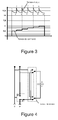
- FIGS. Figures 1A and 1B A basic diagram of an elementary cell according to the invention is shown in FIGS. Figures 1A and 1B .
- the cell is constituted by an electrical storage unit 1, connected in parallel between two terminals 2, 3 of a power line 4, by interposing at least one switch 5.
- the switch is a 2-position switch: S and BP, the terminal corresponding to the BP position being connected to the power line.
- S the terminal corresponding to the BP position
- BP the terminal connected to the power line.
- the position S corresponds to the serialization of the storage unit.
- a voltage limiting system may be provided to limit the voltage across this storage unit.
- the BP position may be forced so as to isolate temporarily or permanently a cell without preventing the operation of a module associating several cells.
- This elementary cell further comprises a command line C for placing the switch in one of the 2 positions according to an order sent by the command line.
- This control line is provided at its ends with means of the socket type, plug, to associate two control lines in series as will be seen later.
- the terminals at the ends of a power line allow cells to be connected in series, as shown for example in FIG. figure 2 , with a module constituted by the series assembly of 3 elementary cells, denoted from bottom to top C1, C2 and C3.
- a module constituted by the series assembly of 3 elementary cells, denoted from bottom to top C1, C2 and C3.
- all the cells of the same module are controlled by a single command line, which assumes different levels of control for individual recognition by each cell as will be detailed below.
- it is also possible to keep an individual command line for each cell which makes it possible to use all identical switches, but adds a number of power lines to the network.
- full bypass mode In the mode of figure 2-A , called "full bypass mode", all storage units of the elementary cells are disconnected and the voltage across the module is zero.
- the voltage at the terminals of the 3-cell module will be between 0 and 2.7 Volts, depending on the load level of the capacity of the cell in series.
- the voltage across the module With two cells in series, always depending on the load level of the capacity of the cells put in series, the voltage across the module will be between 0 and 5.4 Volts. And with the 3 cells mounted in series as in the case illustrated in the Figure 2C , the voltage across the module will vary between 0 and 8.1 volts.
- all the cells use the same command line on which the control signal is sent and to which one or more cells will respond. This can be achieved in particular by control signals consisting of voltage thresholds.
- Another variant consists of pulse trains, which allows individual control with a single command line. This variant, like the first variant, allows more flexibility in the control of the cells.
- each cell having a UCAP capable of being charged at most to 2.7 Volts, and whose maximum nominal voltage is 2.5V.
- the 10 UCAP we will thus load all the UCAP at 1/10 the voltage of the battery, or 1.25 Volts. This value represents less than 50% of the maximum rated voltage.
- the object of the sequence of the commutations is to allow the continuation of the load of the cells
- the 12.5 volts of the battery will be distributed on the 9 cells which remain in series, which therefore see their load increase to correspond to a unit voltage of 1.39 volts.
- the load of all the cells at 1.39 Volts is again equalized.
- the voltage across the module is now 13.89 volts.
- Table I gives an example of a possible succession of switches ensuring the charging of 10 Ucaps with a battery at 12.5 Volts in the case where the cells have a separate individual command. As shown in the table, the final load voltage of the module is 25V for a battery voltage of 12.5V.
- the disconnection of the C8 cell also supposes a disconnection of the C9 and C10 cells. This is why it is advantageous to provide balancing phases during which all or part of the module is isolated from the power source and all or part of the cells are again put in series, so as to homogenize the voltage of any or part of the cells of the module. In practice the balancing phases are to be reduced to be done only when the energies between the cells are significantly different to require a balancing phase.
- a method for charging a set of n electrical storage units each having a maximum unit voltage u n, max characterized in that that a number j (with j less than or equal to n), storage units are put in series to be powered under the voltage U, the number j being adapted to the voltage U and the charge level of the storage units a so that the sum of the unit voltages of the storage units is less than or equal to U and that no storage unit exceeds its maximum unit voltage.
- the loading under voltage U of the storage units can be advantageously continued by excluding i storage units, with i such that the sum of the unit voltages of the storage units is less than or equal to U and that no storage unit exceeds its maximum unit voltage.
- Each exclusion phase of one or more storage units may be preceded and / or followed by one (or more) phase of electrical isolation and serialization of all or part of the n storage units so as to balance the load between all or part of the n storage units
- n-unit module When now the n-unit module is used as a power source, there will of course be a decrease in the state of the cell charges - and it is desirable to regulate the output voltage of the module around a value. setpoint, fixed or modulated, to compensate for the discharge, or voltage drop, dynamic cells.
- the scheme proposed at figure 3 illustrates again the case of 10 Ucaps operating in voltage regulation at 12.5V. Initially, Ucaps are charged at 2.5 volts. With 5 Ucaps in series, the desired setpoint voltage of 12.5 V is available. (Point 1).
- Table III - while in Table I - illustrates a possible implementation of this mode of discharge, assuming 10 Ucaps supplying a regulated load of 12.5V (between 11.25V and 13.75V) initially all charged at 2.5 V, each cell being provided with a single or separate command.
- the case of figure 3 describes a voltage threshold control.
- Table IV - while in Table II - is likewise an illustrative example of the discharge mode with cells provided with independent control, again to provide a regulated load of 12.5V (between 11.25V and 13.50V). ) from a module with all Ucaps initially loaded at 2.5 V.
- the invention thus also proposes a method for regulating the supply of a setpoint voltage U from n storage units, characterized in that storage units are placed in series so that the sum of the The unit voltages of the storage units are close to U, and one or more storage units are added in series as the storage units are discharged in order to maintain a voltage close to the set voltage U.
- Each addition of one or more units may be preceded or followed by a phase of electrical isolation and serialization of all or part of n storage units so as to balance the load between all or part of the n storage units.
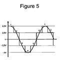
- the unit cell further comprises a polarity inverter, with the addition of a first line of currents
- This type of switching makes it possible to generate different types of electrical signals, for example a sinusoid as illustrated by FIG. figure 5 .
Landscapes
- Engineering & Computer Science (AREA)
- Power Engineering (AREA)
- Manufacturing & Machinery (AREA)
- Chemical & Material Sciences (AREA)
- Chemical Kinetics & Catalysis (AREA)
- Electrochemistry (AREA)
- General Chemical & Material Sciences (AREA)
- Transportation (AREA)
- Mechanical Engineering (AREA)
- Charge And Discharge Circuits For Batteries Or The Like (AREA)
Applications Claiming Priority (1)
| Application Number | Priority Date | Filing Date | Title |
|---|---|---|---|
| FR0758973A FR2923656B1 (fr) | 2007-11-13 | 2007-11-13 | Perfectionnement au domaine des elements de stockage d'energie |
Publications (1)
| Publication Number | Publication Date |
|---|---|
| EP2061116A1 true EP2061116A1 (de) | 2009-05-20 |
Family
ID=39539477
Family Applications (1)
| Application Number | Title | Priority Date | Filing Date |
|---|---|---|---|
| EP08168943A Withdrawn EP2061116A1 (de) | 2007-11-13 | 2008-11-12 | Verbesserung im Bereich der Energiespeicherelemente |
Country Status (2)
| Country | Link |
|---|---|
| EP (1) | EP2061116A1 (de) |
| FR (1) | FR2923656B1 (de) |
Cited By (7)
| Publication number | Priority date | Publication date | Assignee | Title |
|---|---|---|---|---|
| WO2012038252A1 (de) * | 2010-09-20 | 2012-03-29 | Sb Limotive Company Ltd. | Batteriesystem mit variabel einstellbarer zwischenkreisspannung |
| WO2012038149A1 (de) * | 2010-09-20 | 2012-03-29 | Sb Limotive Company Ltd. | Verfahren zum einstellen einer gleichspannungszwischenkreisspannung |
| WO2012038153A1 (de) * | 2010-09-20 | 2012-03-29 | Sb Limotive Company Ltd. | Verfahren zur inbetriebnahme eines batteriesystems mit einem gleichspannungszwischenkreis |
| WO2012038154A1 (de) * | 2010-09-20 | 2012-03-29 | Sb Limotive Company Ltd. | Verfahren zur inbetriebnahme eines batteriesystems mit einem gleichspannungszwischenkreis |
| WO2012052224A1 (de) * | 2010-10-20 | 2012-04-26 | Sb Limotive Company Ltd. | Verfahren zur steuerung einer batterie mit variabler ausgangsspannung |
| DE102017011167A1 (de) * | 2017-12-04 | 2019-06-06 | Belectric Gmbh | Verfahren zum Betreiben eines Batteriespeichersystem |
| WO2022090558A1 (fr) * | 2020-11-02 | 2022-05-05 | Commissariat à l'Energie Atomique et aux Energies Alternatives | Système d'alimentation électrique |
Families Citing this family (1)
| Publication number | Priority date | Publication date | Assignee | Title |
|---|---|---|---|---|
| CN106026282B (zh) * | 2016-07-04 | 2019-10-18 | 深圳伊莱杰科技有限公司 | 一种双枪动态切换控制装置 |
Citations (6)
| Publication number | Priority date | Publication date | Assignee | Title |
|---|---|---|---|---|
| EP0609101A1 (de) * | 1993-01-29 | 1994-08-03 | Canon Kabushiki Kaisha | Vorrichtung zum Speichern von elektrischer Energie und elektrisches Leistungssystem |
| US5773959A (en) * | 1996-01-11 | 1998-06-30 | Lockheed Martin Corporation | Lithium polymer battery charger methods and apparatus |
| US5960898A (en) * | 1996-09-13 | 1999-10-05 | Honda Giken Kogyo Kabushiki Kaisha | Power supply unit and electric vehicle incorporating the same |
| US6323623B1 (en) * | 1999-08-23 | 2001-11-27 | Casio Computer Co., Ltd. | Charging device and charging method thereof |
| US6617830B2 (en) * | 2001-05-10 | 2003-09-09 | Nisshinbo Industries, Inc. | Capacitor system for a vehicle |
| DE102005000979A1 (de) * | 2005-01-07 | 2006-07-20 | Siemens Ag | Schaltungsanordnung und Verfahren zum geschützten Betrieb von Doppelschichtkondensatoren |
-
2007
- 2007-11-13 FR FR0758973A patent/FR2923656B1/fr not_active Expired - Fee Related
-
2008
- 2008-11-12 EP EP08168943A patent/EP2061116A1/de not_active Withdrawn
Patent Citations (6)
| Publication number | Priority date | Publication date | Assignee | Title |
|---|---|---|---|---|
| EP0609101A1 (de) * | 1993-01-29 | 1994-08-03 | Canon Kabushiki Kaisha | Vorrichtung zum Speichern von elektrischer Energie und elektrisches Leistungssystem |
| US5773959A (en) * | 1996-01-11 | 1998-06-30 | Lockheed Martin Corporation | Lithium polymer battery charger methods and apparatus |
| US5960898A (en) * | 1996-09-13 | 1999-10-05 | Honda Giken Kogyo Kabushiki Kaisha | Power supply unit and electric vehicle incorporating the same |
| US6323623B1 (en) * | 1999-08-23 | 2001-11-27 | Casio Computer Co., Ltd. | Charging device and charging method thereof |
| US6617830B2 (en) * | 2001-05-10 | 2003-09-09 | Nisshinbo Industries, Inc. | Capacitor system for a vehicle |
| DE102005000979A1 (de) * | 2005-01-07 | 2006-07-20 | Siemens Ag | Schaltungsanordnung und Verfahren zum geschützten Betrieb von Doppelschichtkondensatoren |
Cited By (20)
| Publication number | Priority date | Publication date | Assignee | Title |
|---|---|---|---|---|
| KR101464574B1 (ko) * | 2010-09-20 | 2014-11-24 | 로베르트 보쉬 게엠베하 | Dc 전압 중간 회로의 전압 조정 방법 |
| US9457745B2 (en) | 2010-09-20 | 2016-10-04 | Robert Bosch Gmbh | Method for starting up a battery system having a DC voltage intermediate circuit |
| WO2012038153A1 (de) * | 2010-09-20 | 2012-03-29 | Sb Limotive Company Ltd. | Verfahren zur inbetriebnahme eines batteriesystems mit einem gleichspannungszwischenkreis |
| WO2012038154A1 (de) * | 2010-09-20 | 2012-03-29 | Sb Limotive Company Ltd. | Verfahren zur inbetriebnahme eines batteriesystems mit einem gleichspannungszwischenkreis |
| US20130278052A1 (en) * | 2010-09-20 | 2013-10-24 | Samsung Sdi Co., Ltd. | Method for Starting Up a Battery System Having a DC Voltage Intermediate Circuit |
| CN103119776A (zh) * | 2010-09-20 | 2013-05-22 | Sb锂摩托有限公司 | 一种用于调试具有直流中间电路的蓄电池系统的方法 |
| CN103155262A (zh) * | 2010-09-20 | 2013-06-12 | 罗伯特·博世有限公司 | 用于调节直流中间电路电压的方法 |
| WO2012038252A1 (de) * | 2010-09-20 | 2012-03-29 | Sb Limotive Company Ltd. | Batteriesystem mit variabel einstellbarer zwischenkreisspannung |
| KR101464696B1 (ko) * | 2010-09-20 | 2014-11-24 | 로베르트 보쉬 게엠베하 | Dc 전압 중간 회로를 포함하는 배터리 시스템의 작동 개시 방법 |
| WO2012038149A1 (de) * | 2010-09-20 | 2012-03-29 | Sb Limotive Company Ltd. | Verfahren zum einstellen einer gleichspannungszwischenkreisspannung |
| CN103153687A (zh) * | 2010-09-20 | 2013-06-12 | 罗伯特·博世有限公司 | 具有可可变地调节的中间电路电压的蓄电池系统 |
| US9024560B2 (en) | 2010-09-20 | 2015-05-05 | Robert Bosch Gmbh | Method for adjusting a DC voltage intermediate-circuit voltage |
| US9045054B2 (en) | 2010-09-20 | 2015-06-02 | Robert Bosch Gmbh | Battery system having an intermediate circuit voltage which can be set in a variable fashion |
| CN103155262B (zh) * | 2010-09-20 | 2015-08-05 | 罗伯特·博世有限公司 | 用于调节直流中间电路电压的方法 |
| CN103119776B (zh) * | 2010-09-20 | 2015-11-25 | 罗伯特·博世有限公司 | 一种用于调试具有直流中间电路的蓄电池系统的方法 |
| US9276427B2 (en) | 2010-09-20 | 2016-03-01 | Robert Bosch Gmbh | Method for starting up a battery system having a DC voltage intermediate circuit |
| CN103153687B (zh) * | 2010-09-20 | 2016-09-28 | 罗伯特·博世有限公司 | 具有可可变地调节的中间电路电压的蓄电池系统 |
| WO2012052224A1 (de) * | 2010-10-20 | 2012-04-26 | Sb Limotive Company Ltd. | Verfahren zur steuerung einer batterie mit variabler ausgangsspannung |
| DE102017011167A1 (de) * | 2017-12-04 | 2019-06-06 | Belectric Gmbh | Verfahren zum Betreiben eines Batteriespeichersystem |
| WO2022090558A1 (fr) * | 2020-11-02 | 2022-05-05 | Commissariat à l'Energie Atomique et aux Energies Alternatives | Système d'alimentation électrique |
Also Published As
| Publication number | Publication date |
|---|---|
| FR2923656A1 (fr) | 2009-05-15 |
| FR2923656B1 (fr) | 2011-05-20 |
Similar Documents
| Publication | Publication Date | Title |
|---|---|---|
| EP2061116A1 (de) | Verbesserung im Bereich der Energiespeicherelemente | |
| EP2351188B1 (de) | Ununterbrechbare gleichstrom-stromversorgungseinrichtung für ein datenverarbeitungssystem mit mindestens einem prozessor | |
| EP2079148A2 (de) | Elektrischer Schaltkreis | |
| FR3039313B1 (fr) | Dispositif reconfigurable de stockage d'energie par effet capacitif, systeme d'alimentation et vehicule electrique integrant ce dispositif | |
| EP3758969A1 (de) | Versorgungsmodul für einen elektrofahrzeugmotor | |
| EP3016817A1 (de) | Elektrisches fahrzeug und entsprechende transportvorrichtung | |
| FR2996374A1 (fr) | Reseau electrique pour vehicule automobile | |
| FR2903048A1 (fr) | Procede et dispositif micro-hybride pour vehicule automobile | |
| EP3224923B1 (de) | Batteriepack für ein kraftfahrzeug | |
| EP2831977A2 (de) | Verfahren und system zur stromversorgung eines hybridkraftfahrzeugs mit zwei stromspeichern | |
| FR2926169A1 (fr) | Circuit electrique comportant un moyen de stockage electrique apte a fournir une tension variable | |
| FR2871744A1 (fr) | Dispositif d'alimentation embarque sur un vehicule de traction, procede d'alimentation et support d'enregistrement de ce procede | |
| EP3844032A1 (de) | Elektrische schaltung und kraftfahrzeug mit solch einer schaltung | |
| EP2801150A1 (de) | System zur bereitstellung einer wechselstromlast aus mehreren gleichspannungsquellen | |
| WO2022106798A1 (fr) | Système de stockage hybride pour réseau électrique d'urgence d'aéronef | |
| EP3760490B1 (de) | Schaltkreis und kraftfahrzeug, das einen solchen schaltkreis umfasst | |
| WO2022090558A1 (fr) | Système d'alimentation électrique | |
| WO2019166732A2 (fr) | Module d'alimentation pour moteur de véhicule électrique, avec transfert thermique | |
| EP4002624A1 (de) | Stromversorgungssystem | |
| EP4043270A1 (de) | Stromversorgungssystem, entsprechendes verfahren und computerprogramm | |
| FR2912850A1 (fr) | Vehicule de transport en commun, procede d'utilisation et bloc batterie pour ce vehicule | |
| FR3083173A1 (fr) | Systeme de stockage d'energie embarque | |
| EP2144322A2 (de) | Wiederaufladbares Akku-Set mit elektronischen Steuerschaltkreisen | |
| WO2016193080A1 (fr) | Dispositif d'alimentation d'un recepteur electrique avec commutation entre deux sources de tension continue, et procede d'alimentation mettant en oeuvre un tel dispositif | |
| FR3010833A3 (fr) | Batterie pour vehicule hybride |
Legal Events
| Date | Code | Title | Description |
|---|---|---|---|
| PUAI | Public reference made under article 153(3) epc to a published international application that has entered the european phase |
Free format text: ORIGINAL CODE: 0009012 |
|
| AK | Designated contracting states |
Kind code of ref document: A1 Designated state(s): AT BE BG CH CY CZ DE DK EE ES FI FR GB GR HR HU IE IS IT LI LT LU LV MC MT NL NO PL PT RO SE SI SK TR |
|
| AX | Request for extension of the european patent |
Extension state: AL BA MK RS |
|
| 17P | Request for examination filed |
Effective date: 20091001 |
|
| 17Q | First examination report despatched |
Effective date: 20091028 |
|
| AKX | Designation fees paid |
Designated state(s): AT BE BG CH CY CZ DE DK EE ES FI FR GB GR HR HU IE IS IT LI LT LU LV MC MT NL NO PL PT RO SE SI SK TR |
|
| STAA | Information on the status of an ep patent application or granted ep patent |
Free format text: STATUS: THE APPLICATION IS DEEMED TO BE WITHDRAWN |
|
| 18D | Application deemed to be withdrawn |
Effective date: 20100508 |