EP2060926A1 - Magnetic sensor - Google Patents
Magnetic sensor Download PDFInfo
- Publication number
- EP2060926A1 EP2060926A1 EP07713899A EP07713899A EP2060926A1 EP 2060926 A1 EP2060926 A1 EP 2060926A1 EP 07713899 A EP07713899 A EP 07713899A EP 07713899 A EP07713899 A EP 07713899A EP 2060926 A1 EP2060926 A1 EP 2060926A1
- Authority
- EP
- European Patent Office
- Prior art keywords
- magnetoresistance effect
- magnetic field
- effect element
- resistance value
- external magnetic
- Prior art date
- Legal status (The legal status is an assumption and is not a legal conclusion. Google has not performed a legal analysis and makes no representation as to the accuracy of the status listed.)
- Granted
Links
- 230000005291 magnetic effect Effects 0.000 title claims abstract description 415
- 230000000694 effects Effects 0.000 claims abstract description 250
- 230000008859 change Effects 0.000 claims abstract description 49
- 230000004044 response Effects 0.000 claims abstract description 42
- 239000010410 layer Substances 0.000 claims description 129
- 230000005415 magnetization Effects 0.000 claims description 49
- 238000009812 interlayer coupling reaction Methods 0.000 claims description 41
- 230000007423 decrease Effects 0.000 claims description 14
- 230000005290 antiferromagnetic effect Effects 0.000 claims description 13
- 230000001413 cellular effect Effects 0.000 description 22
- BGPVFRJUHWVFKM-UHFFFAOYSA-N N1=C2C=CC=CC2=[N+]([O-])C1(CC1)CCC21N=C1C=CC=CC1=[N+]2[O-] Chemical compound N1=C2C=CC=CC2=[N+]([O-])C1(CC1)CCC21N=C1C=CC=CC1=[N+]2[O-] BGPVFRJUHWVFKM-UHFFFAOYSA-N 0.000 description 12
- 238000010586 diagram Methods 0.000 description 7
- 238000000034 method Methods 0.000 description 7
- 238000009832 plasma treatment Methods 0.000 description 7
- 230000004048 modification Effects 0.000 description 5
- 238000012986 modification Methods 0.000 description 5
- 230000008569 process Effects 0.000 description 5
- 239000000463 material Substances 0.000 description 4
- 239000000758 substrate Substances 0.000 description 4
- 239000000956 alloy Substances 0.000 description 3
- 229910045601 alloy Inorganic materials 0.000 description 3
- 238000000137 annealing Methods 0.000 description 3
- 230000003247 decreasing effect Effects 0.000 description 3
- 238000001514 detection method Methods 0.000 description 3
- 238000009434 installation Methods 0.000 description 3
- 230000003993 interaction Effects 0.000 description 3
- 239000000696 magnetic material Substances 0.000 description 3
- 230000002441 reversible effect Effects 0.000 description 3
- 239000002885 antiferromagnetic material Substances 0.000 description 2
- 230000008878 coupling Effects 0.000 description 2
- 238000010168 coupling process Methods 0.000 description 2
- 238000005859 coupling reaction Methods 0.000 description 2
- 229910052735 hafnium Inorganic materials 0.000 description 2
- 239000004973 liquid crystal related substance Substances 0.000 description 2
- 238000004519 manufacturing process Methods 0.000 description 2
- 229910052750 molybdenum Inorganic materials 0.000 description 2
- 229910052758 niobium Inorganic materials 0.000 description 2
- 239000011241 protective layer Substances 0.000 description 2
- 229910052715 tantalum Inorganic materials 0.000 description 2
- 229910052719 titanium Inorganic materials 0.000 description 2
- 229910052726 zirconium Inorganic materials 0.000 description 2
- 229910003321 CoFe Inorganic materials 0.000 description 1
- 229910019233 CoFeNi Inorganic materials 0.000 description 1
- 229910001030 Iron–nickel alloy Inorganic materials 0.000 description 1
- 229910019041 PtMn Inorganic materials 0.000 description 1
- 229910003087 TiOx Inorganic materials 0.000 description 1
- 229910052782 aluminium Inorganic materials 0.000 description 1
- 230000004888 barrier function Effects 0.000 description 1
- 229910052793 cadmium Inorganic materials 0.000 description 1
- 244000145845 chattering Species 0.000 description 1
- 229910052804 chromium Inorganic materials 0.000 description 1
- 239000004020 conductor Substances 0.000 description 1
- 229910052802 copper Inorganic materials 0.000 description 1
- 229910052733 gallium Inorganic materials 0.000 description 1
- 229910052732 germanium Inorganic materials 0.000 description 1
- 229910052737 gold Inorganic materials 0.000 description 1
- 229910052741 iridium Inorganic materials 0.000 description 1
- 229910052742 iron Inorganic materials 0.000 description 1
- 229910052745 lead Inorganic materials 0.000 description 1
- 229910052759 nickel Inorganic materials 0.000 description 1
- 229910052762 osmium Inorganic materials 0.000 description 1
- 229910052763 palladium Inorganic materials 0.000 description 1
- 229910052697 platinum Inorganic materials 0.000 description 1
- 229910052761 rare earth metal Inorganic materials 0.000 description 1
- 229910052702 rhenium Inorganic materials 0.000 description 1
- 229910052703 rhodium Inorganic materials 0.000 description 1
- 229910052707 ruthenium Inorganic materials 0.000 description 1
- 230000035945 sensitivity Effects 0.000 description 1
- 229910052709 silver Inorganic materials 0.000 description 1
- 230000001360 synchronised effect Effects 0.000 description 1
- 229910052718 tin Inorganic materials 0.000 description 1
- HLLICFJUWSZHRJ-UHFFFAOYSA-N tioxidazole Chemical compound CCCOC1=CC=C2N=C(NC(=O)OC)SC2=C1 HLLICFJUWSZHRJ-UHFFFAOYSA-N 0.000 description 1
- 229910052721 tungsten Inorganic materials 0.000 description 1
- 229910052720 vanadium Inorganic materials 0.000 description 1
- 229910052725 zinc Inorganic materials 0.000 description 1
Images


Classifications
-
- H—ELECTRICITY
- H04—ELECTRIC COMMUNICATION TECHNIQUE
- H04M—TELEPHONIC COMMUNICATION
- H04M1/00—Substation equipment, e.g. for use by subscribers
- H04M1/02—Constructional features of telephone sets
- H04M1/0202—Portable telephone sets, e.g. cordless phones, mobile phones or bar type handsets
- H04M1/0206—Portable telephones comprising a plurality of mechanically joined movable body parts, e.g. hinged housings
- H04M1/0241—Portable telephones comprising a plurality of mechanically joined movable body parts, e.g. hinged housings using relative motion of the body parts to change the operational status of the telephone set, e.g. switching on/off, answering incoming call
- H04M1/0245—Portable telephones comprising a plurality of mechanically joined movable body parts, e.g. hinged housings using relative motion of the body parts to change the operational status of the telephone set, e.g. switching on/off, answering incoming call using open/close detection
-
- B—PERFORMING OPERATIONS; TRANSPORTING
- B82—NANOTECHNOLOGY
- B82Y—SPECIFIC USES OR APPLICATIONS OF NANOSTRUCTURES; MEASUREMENT OR ANALYSIS OF NANOSTRUCTURES; MANUFACTURE OR TREATMENT OF NANOSTRUCTURES
- B82Y25/00—Nanomagnetism, e.g. magnetoimpedance, anisotropic magnetoresistance, giant magnetoresistance or tunneling magnetoresistance
-
- G—PHYSICS
- G01—MEASURING; TESTING
- G01R—MEASURING ELECTRIC VARIABLES; MEASURING MAGNETIC VARIABLES
- G01R33/00—Arrangements or instruments for measuring magnetic variables
- G01R33/02—Measuring direction or magnitude of magnetic fields or magnetic flux
- G01R33/06—Measuring direction or magnitude of magnetic fields or magnetic flux using galvano-magnetic devices
- G01R33/07—Hall effect devices
-
- G—PHYSICS
- G01—MEASURING; TESTING
- G01R—MEASURING ELECTRIC VARIABLES; MEASURING MAGNETIC VARIABLES
- G01R33/00—Arrangements or instruments for measuring magnetic variables
- G01R33/02—Measuring direction or magnitude of magnetic fields or magnetic flux
- G01R33/06—Measuring direction or magnitude of magnetic fields or magnetic flux using galvano-magnetic devices
- G01R33/09—Magnetoresistive devices
- G01R33/093—Magnetoresistive devices using multilayer structures, e.g. giant magnetoresistance sensors
-
- H—ELECTRICITY
- H04—ELECTRIC COMMUNICATION TECHNIQUE
- H04M—TELEPHONIC COMMUNICATION
- H04M2250/00—Details of telephonic subscriber devices
- H04M2250/12—Details of telephonic subscriber devices including a sensor for measuring a physical value, e.g. temperature or motion
Definitions
- the present invention relates to magnetic sensors having a magnetoresistance effect element and, in particular, to a magnetic sensor operating stably in a bipolar fashion regardless of a polarity of an external magnetic field.
- a magnetic sensor operating in a contactless fashion employs a Hall element, a magnetoresistance effect element, or the like.
- a magnetic sensor having a magnetoresistance effect element draws attention because the Hall element consumes high power, needs a hysteresis circuit due to lack of hysteresis, and has difficulty in the miniaturization thereof.
- Such a magnetic sensor has been recently used to detect the opening of a flip cellular phone or the like.
- a magnetoresistance effect element and a fixed resistance element are used and connected in series.
- a voltage between the elements is output so that on-off changing signals are output in response to a change in the output caused by a change in a magnetic field strength of an external magnetic field.
- a backlight beneath a display screen or the like is controlled to light.
- the above-described opening detection method has the problem described below. Since a change in the resistance of the magnetoresistance effect element depends on the polarity of the external magnetic field, the direction of a magnet placed to face the magnetic sensor is limited. More specifically, if the magnet is placed in a direction opposite to a correct direction, the polarity of the external magnetic field is reversed. The resistance value of the magnetoresistance effect element remains unchanged in response to a change in the magnetic field strength of the external magnetic field having the reversed polarity, and the opening detection fails to operate properly.
- the present invention is intended to overcome the above-described problem, and in particular, it is an object of the present invention to provide a magnetic sensor having a magnetoresistance effect element that operates in a bipolar fashion regardless of the polarity of the external magnetic field.
- a magnetic sensor of the present invention includes a series circuit that connects in a serial connection a first magnetoresistance effect element and a second magnetoresistance effect element, each element having a resistance thereof changing in response to a change in a magnetic field strength of an external magnetic field, and outputs a voltage at a junction between the first magnetoresistance effect element and the second magnetoresistance effect element.
- the first magnetoresistance effect element changes the resistance thereof in response to a change in the magnetic field strength in a positive direction of the external magnetic field while the second magnetoresistance effect element maintains a constant resistance value, the one direction of the external magnetic field being the positive direction and the direction opposite to the one direction being a negative direction.
- the second magnetoresistance effect element changes the resistance thereof in response to a change in the magnetic field strength in the negative direction of the external magnetic field while the first magnetoresistance effect element maintains a constant resistance value.
- the magnetic sensor operating in a bipolar fashion regardless of the polarity of the external magnetic field is provided.
- External magnetic field generating means such as a magnet is free from installation restrictions in comparison with the related art, and the assembling of the magnetic sensor is easy.
- an increase and decrease trend in the resistance change of the first magnetoresistance effect element in response to a change in the positive direction in the magnetic field strength and an increase and decrease trend in the resistance change of the second magnetoresistance effect element in response to a change in the negative direction in the magnetic field strength are preferably reversed with respect to a non-magnetic state of the external magnetic field.
- a fixed resistance value X1 of the second magnetoresistance effect element with the external magnetic field in the positive direction is larger than a minimum resistance value X2 of the first magnetoresistance effect element changing in response to a change in the magnetic intensity in the positive direction and smaller than a maximum resistance value X3 of the first magnetoresistance effect element changing in response to a change in the magnetic intensity in the positive direction.
- a fixed resistance value X4 of the first magnetoresistance effect element with the external magnetic field in the negative direction is larger than a minimum resistance value X5 of the second magnetoresistance effect element changing in response to a change in the magnetic intensity in the negative direction and smaller than a maximum resistance value X6 of the second magnetoresistance effect element changing in response to a change in the magnetic intensity in the negative direction.
- a ratio of (the fixed resistance value X1 - the minimum resistance value X2: the maximum resistance value X3 - the fixed resistance value X1) is equal to a ratio of (the maximum resistance value X6 - the fixed resistance value X4: the fixed resistance value X4 - the minimum resistance value X5).
- the fixed resistance value X1 is a median value between the minimum resistance value X2 and the maximum resistance value X3
- the fixed resistance value X4 is a median value between the minimum resistance value X5 and the maximum resistance value X6.
- a timing at which the varying resistance of the first magnetoresistance effect element becomes equal to the fixed resistance value X1 of the second magnetoresistance effect element when the external magnetic field operates in the positive direction There is also provided a timing at which the varying resistance of the second magnetoresistance effect element becomes equal to the fixed resistance value X4 of the first magnetoresistance effect element when the external magnetic field operates in the negative direction.
- the voltage at this timing is set to be a threshold value for switching the changing signals. In accordance with the present invention, such an adjustment causes the same timing to be applied regardless of whether the external magnetic field is positive or negative.
- the magnetic sensor as a bipolar operating magnetic sensor is easily adjusted in threshold voltage without any offset, and operates reliably.
- the first magnetoresistance effect element and the second magnetoresistance effect element have preferably the same layer structure composed of an antiferromagnetic layer, a fixed magnetic layer, a nonmagnetic intermediate layer, and a free magnetic layer.
- a first interlayer coupling magnetic field Hin1 acting on the fixed magnetic layer and the free magnetic layer of the first magnetoresistance effect element is preferably shifted in the positive direction of the external magnetic field
- a second interlayer coupling magnetic field Hin2 acting on the fixed magnetic layer and the free magnetic layer of the second magnetoresistance effect element is preferably shifted in the negative direction of the external magnetic field.
- the above-described adjustment causes a so-called hysteresis loop to form in a positive region of the external magnetic field in the first magnetoresistance effect element and a hysteresis loop in a negative region of the external magnetic field in the second magnetoresistance effect element.
- the first magnetoresistance effect element changes the resistance thereof in response to a change in the magnetic field strength in the positive direction of the external magnetic field while the second magnetoresistance effect element maintains a constant resistance value
- the second magnetoresistance effect element changes the resistance thereof in response to a change in the magnetic field strength in the negative direction of the external magnetic field while the first magnetoresistance effect element maintains a constant resistance value.
- the bipolar operating magnetic sensor is easily and appropriately constructed.
- the first interlayer coupling magnetic field Hin1 and the second interlayer coupling magnetic field Hin2 preferably have the same magnitude (in the absolute value).
- the magnetic sensor reliably operates as a bipolar operating magnetic sensor.
- the magnetization of the fixed magnetic layer and the magnetization of the free magnetic layer in one of the first magnetoresistance effect element and the second magnetoresistance effect element are in the same direction in the non-magnetic state of the external magnetic field, the magnetization of the fixed magnetic layer and the magnetization of the free magnetic layer in the other of the first magnetoresistance effect element and the second magnetoresistance effect element are anti-parallel to each other, and the magnetization of the fixed magnetic layer of the first magnetoresistance effect element and the magnetization of fixed magnetic layer of the second magnetoresistance effect element are aligned in the same direction.
- first magnetoresistance effect elements and two second magnetoresistance effect elements are arranged, a first serial circuit is formed of one of the first magnetoresistance effect elements and one of the second magnetoresistance effect elements, and a second serial circuit is formed of the remaining first magnetoresistance effect element and the remaining second magnetoresistance effect element.
- the first magnetoresistance effect element in the first serial circuit and the second magnetoresistance effect element in the second serial circuit are preferably connected in parallel and the second magnetoresistance effect element in the first serial circuit and the first magnetoresistance effect element in the second serial circuit are connected in parallel.
- a difference between a voltage at a junction of the first serial circuit and a voltage at a junction of the second serial circuit is preferably output as a differential voltage.
- the present invention provides a bipolar operating magnetic sensor that operates regardless of the polarity of an external magnetic field.
- a magnet generating an external magnetic field is free from installation restrictions in comparison with the related art, and the assembling of the magnetic sensor is easy.
- Figs. 1 through 4 are partial diagrammatic views of a flip cellular phone containing a contactless magnetic sensor in accordance with a present embodiment.
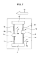
- Figs. 5 and 7 are partial plan views of the contactless magnetic sensor of the present embodiment.
- Figs. 6 and 8 are circuit diagrams of the magnetic sensor.
- Fig. 9 is a partial sectional view of the contactless magnetic sensor taken along line A-A and viewed from arrows in Fig. 5 .
- Fig. 10A is a graph (R-H curve) representing hysteresis characteristics of a first magnetoresistance effect element
- Fig. 10B is a graph (R-H curve) representing hysteresis characteristics of a second magnetoresistance effect element
- FIG. 10C is a graph (R-H curve) combining the hysteresis characteristics of Figs. 10A and 10B .
- Fig. 11 is a graph representing a relationship between an external magnetic field and a differential voltage.
- Fig. 12 is a graph representing a relationship of a gas pressure and a power value during plasma treatment and an interlayer coupling magnetic field Hin.
- a flip cellular phone 1 includes a first unit 2 and a second unit 3.
- the first unit 2 is on a display screen side
- the second unit 3 is an operation body side.
- a liquid-crystal display, a receiver, etc. are arranged on a facing surface of the first unit 2 facing the second unit 3.
- a variety of buttons, a microphone, etc. are arranged on a facing surface of the first unit 2 facing the second unit 3.
- Fig. 1 illustrates the flip cellular phone 1 in the closed state thereof.
- the first unit 2 includes a magnet 5
- the second unit 3 includes a magnet sensor 4.
- the magnet 5 and the magnet sensor 4 are arranged in mutually facing positions thereof.
- the magnet sensor 4 may be arranged in a position slightly shifted from the facing position to the magnet 5 in a direction parallel with an incident direction of an external magnetic field H1.
- the external magnetic field H1 emitted from the magnet 5 reaches the magnet sensor 4.
- the magnet sensor 4 detects the external magnetic field H1, thereby detecting that the flip cellular phone 1 is in the closed state thereof.
- the flip cellular phone 1 when the flip cellular phone 1 is opened as illustrated in Fig. 2 , the external magnetic field H1 reaching the magnet sensor 4 gradually decreases in magnitude as the first unit 2 is spaced apart from the second unit 3. Finally, the external magnetic field H1 reaching the magnet sensor 4 becomes zero.
- a controller included in the flip cellular phone 1 controls a back light beneath the liquid-crystal display and the operational buttons to flash.
- the magnet sensor 4 of the present embodiment is a bipolar operative sensor. More specifically, an N pole of the magnet 5 is placed on the right-hand side and an S pole of the magnet 5 is placed on the left-hand side in Fig. 1 . If the polarity is reversed as shown in Fig. 3 (the N pole on the right-hand side and the S pole on the left-hand side), the direction of an external magnetic field H2 reaching the magnet sensor 4 is reversed from the direction of the external magnetic field H1 of Fig. 1 . In accordance with the present embodiment, in such a case, the opening of the flip cellular phone 1 is adequately detected when the flip cellular phone 1 is opened as illustrated in Fig. 4 from the closed state of the flip cellular phone 1 illustrated in Fig. 3 .
- the magnet sensor 4 of the present embodiment is mounted on a circuit board 6 to be contained in the second unit 3.
- the magnet sensor 4 includes two first magnetoresistance effect elements 10 and 11, and two second magnetoresistance effect elements 12 and 13, arranged on one element substrate 7.
- the magnetoresistance effect elements 10-13 form a bridge circuit.
- the first magnetoresistance effect element 10 and the second magnetoresistance effect element 12 are connected in a serial connection to form a first serial circuit 14.
- the first magnetoresistance effect element 11 and the second magnetoresistance effect element 13 are connected in a serial connection to form a second serial circuit 15.
- the first magnetoresistance effect element 10 in the first serial circuit 14 and the second magnetoresistance effect element 13 in the second serial circuit 15 are connected in a parallel circuit, and a junction of the two elements serves as an input terminal 16. Also, the second magnetoresistance effect element 12 in the first serial circuit 14 and the first magnetoresistance effect element 11 in the second serial circuit are connected in a parallel connection, and a junction of the two elements serves as a ground terminal 17.
- a first junction between the first magnetoresistance effect element 10 and the second magnetoresistance effect element 12 in the first serial circuit 14 is a first output terminal 18.
- a second junction between the first magnetoresistance effect element 11 and the second magnetoresistance effect element 13 in the second serial circuit 15 is a second output terminal 19.
- the terminals 16-19 are electrically connected to unshown respective terminals on the circuit board 6 through wire bonding or die-bonding.
- the first output terminal 18 and the second output terminal 19 are connected to a differential amplifier (operational amplifier) 20, and further to a controller 21.
- Each of the first magnetoresistance effect elements 10 and 11 and the second magnetoresistance effect elements 12 and 14 has the layer structure described below.
- each the first magnetoresistance effect element 10 (11) and the second magnetoresistance effect element 13 (12) includes from the bottom thereof a substrate layer 30, a seed layer 31, an antiferromagnetic layer 32, a fixed magnetic layer 33, a nonmagnetic intermediate layer 34, free magnetic layers 35 and 37 (the free magnetic layer of the second magnetoresistance effect element 13 being designated with the reference number 37), and a protective layer 36 in that order.
- the substrate layer 30 is made of one non-magnetic material selected from or two or more non-magnetic materials selected from Ta, Hf, Nb, Zr, Ti, and Mo.
- the seed layer 31 is made of NiFeCr, Cr, or the like.
- the antiferromagnetic layer 32 is made of an antiferromagnetic material containing an element ⁇ (the element ⁇ is one element or two or more elements selected from Pt, Ir, Pd, Rh, Ru, and Os) and Mn, or an antiferromagnetic material containing the element ⁇ , an element ⁇ ' (the element ⁇ ' containing one element or two or more elements selected from Ne, Ar, Kr, Xe, Be, B, C, N, Mg, Al, Si, P, Ti, V, Cr, Fe, Co, Ni, Cu, Zn, Ga, Ge, Zr, Nb, Mo, Ag, Cd, Sn, Hf, Ta, W, Re, Au, Pb, and rare-earth elements), and Mn.
- an element ⁇ ' the element ⁇ ' containing one element or two or more elements selected from Ne, Ar, Kr, Xe, Be, B, C, N, Mg, Al, Si, P, Ti, V, Cr, Fe, Co, Ni, Cu, Zn
- the antiferromagnetic layer 32 is made or IrMn or PtMn.
- the fixed magnetic layer 33, and the free magnetic layers 35 and 37 are made of a magnetic material of a CoFe alloy, an NiFe alloy, a CoFeNi alloy, etc.
- the nonmagnetic intermediate layer 34 is made of a non-magnetic conductive material such as Cu.
- the nonmagnetic intermediate layer 34 is made of an insulating barrier layer of TiOx or the like.
- the protective layer 36 is made of Ta or the like.
- the fixed magnetic layer 33 and the free magnetic layers 35 and 37 have a layered ferri structure (the layered structure of the magnetic layer/nonmagnetic layer/magnetic layer with the two magnetic layers, sandwiching the non-magnetic layer, having magnetizations thereof in anti-parallel directions).
- the fixed magnetic layer 33 and the free magnetic layers 35 and 37 may have a layered structure made of a plurality of magnetic layers of different materials.
- An exchange coupling magnetic field (Hex) is generated between the antiferromagnetic layer 32 and the fixed magnetic layer 33 in each of the first magnetoresistance effect element 10 and the second magnetoresistance effect element 13 because the antiferromagnetic layer 32 and the fixed magnetic layer 33 in direct contact with each other are annealed under a magnetic field, and the magnetization direction of the fixed magnetic layer 33 is fixed to one direction.
- a magnetization direction 33a of the fixed magnetic layer 33 is denoted by an arrow.
- the magnetization direction 33a of the fixed magnetic layer 33 is in an X2 direction as shown.
- the magnetization direction of the free magnetic layers 35 and 37 is different between the first magnetoresistance effect element 10 and the second magnetoresistance effect element 13.
- a magnetization direction 35a of the free magnetic layer 35 in the first magnetoresistance effect element 10 (11) is the X2 direction as shown, and is thus the same direction as the magnetization direction 33a of the fixed magnetic layer 33, but a magnetization direction 37a of the free magnetic layer 37 in the second magnetoresistance effect element 13 (12) is an X1 direction as shown, and is thus anti-parallel to the magnetization direction 33a of the fixed magnetic layer 33.
- the external magnetic field H1 illustrated in Figs. 1 and 2 impinges on the magnet sensor 4 from the illustrated X2 side to the illustrated X1 direction.
- the direction of the external magnetic field H1 is referred to as a "positive (plus) direction.”
- the external magnetic field H2 illustrated in Figs. 3 and 4 impinges on the magnet sensor 4 from the illustrated X1 to the illustrated X2 direction.
- the direction of the external magnetic field H2 is referred to as a "negative (minus) direction.”
- Fig. 10A illustrates an R-H curve representing the hysteresis characteristics of the first magnetoresistance effect elements 10 and 11.
- the ordinate represents a resistance value R, but may represent a rate of change of resistance (%).
- the resistance value R of the first magnetoresistance effect elements 10 and 11 gradually increases along a curve HR1.
- the minimum resistance value in the range of the varying resistance value is referred to as X2.
- the maximum resistance value within the range of the varying resistance value is referred to as X3.
- a hysteresis loop defined by the curve HR1 and the curve HR2 is formed in response to the magnetic field strength change in the positive direction of the external magnetic field H1 in the first magnetoresistance effect elements 10 and 11.
- a median value between the maximum resistance value X3 and the minimum resistance value X2, i.e., a central value of the breadth of the hysteresis loop HR-A is a "center point" of the hysteresis loop HR-A.
- a second interlayer coupling magnetic field Hin2 in Fig. 10B is also determined in the same manner. Also, the breadth of the hysteresis loop HR-A along the center point is equal to twice the coercive force. If the coercive force is too small, problems arises, for example, chattering is likely to occur. The coercive force is preferably larger to some extent. The coercive force is adjusted to 2.5 Oe or so.
- the first interlayer coupling magnetic field Hin1 shifts in the positive magnetic field direction in the first magnetoresistance effect elements 10 and 11. If the external magnetic field H1 is increased in the positive direction, the magnetic field strength of the external magnetic field H1 maintains the maximum resistance value X3 up to the position of B. If the external magnetic field H1 is further increased beyond the position of B, even the magnetization direction 33a of the fixed magnetic layer 33 becomes aligned with the direction of the external magnetic field H1. The magnetization direction 33a starts to orient in the same direction together with the magnetization direction 35a of the free magnetic layer 35.
- the resistance value R of the first magnetoresistance effect elements 10 and 11 gradually decreases, but in practice, the magnet 5 having a magnetic field strength greater than B is not used.
- the free magnetic layer 35 is not varied in response to a change in the magnetic field strength in the negative direction of the external magnetic field H2 because the direction of the external magnetic field H2 is aligned with the direction of the magnetization direction 35a of the free magnetic layer 35 at non-magnetic field state (no external magnetic field) in the first magnetoresistance effect elements 10 and 11.
- the magnetization direction 35a of the free magnetic layer 35 and the magnetization direction 33a of the fixed magnetic layer 33 are thus maintained in a parallel state.
- the resistance value R of the first magnetoresistance effect elements 10 and 11 maintains a constant resistance value (fixed resistance value) X4 in the negative direction external magnetic field H2 as illustrated in Fig. 10A .
- the hysteresis characteristics of the second magnetoresistance effect elements 12 and 13 are described below.
- the magnetization direction 37a of the free magnetic layer 37 magnetized in the same direction as the external magnetic field H1 remains unchanged. Even if the external magnetic field H as the external magnetic field H1 increases from the position of zero as illustrated in Fig. 10B , the second magnetoresistance effect elements 12 and 13 maintain a constant resistant value (fixed resistance value) X1.
- the magnetization direction 33a of the fixed magnetic layer 33 of the second magnetoresistance effect elements 12 and 13 is reversed to the direction of the external magnetic field H1, and the resistance value R of the second magnetoresistance effect elements 12 and 13 thus starts decreasing.
- the magnet 5 causing the external magnetic field H1 to be larger than a magnetic field strength C is not used in practice.
- the direction of the external magnetic field H2 and the magnetization direction 37a of the free magnetic layer 37 at the non-magnetic field state (zero external magnetic field) of the second magnetoresistance effect elements 12 and 13 are anti-parallel to each other.
- the magnetization direction 37a of the free magnetic layer 37 is affected by the external magnetic field H2 in the negative direction and is thus varied. Since the magnetization direction 33a of the fixed magnetic layer 33 of the second magnetoresistance effect elements 12 and 13 is anti-parallel to the magnetization direction 37a of the free magnetic layer 37 with the external magnetic field H at non-magnetic field state as illustrated in Fig. 9 , the resistance value R becomes high.
- the magnetization direction 37a of the free magnetic layer 37 starts to reverse with the external magnetic field H2 in the negative direction (absolute value) gradually increasing, the magnetization direction 37a of the free magnetic layer 37 becomes closer to the magnetization direction 33a of the fixed magnetic layer 33.
- the resistance value R of the second magnetoresistance effect elements 12 and 13 gradually decreases along the curve HR3.
- the minimum resistance value within the range of varying resistance value R is referred to X5.
- the maximum resistance value within the range of varying resistance value R is referred to as X6.
- the second interlayer coupling magnetic field Hin2 of the second magnetoresistance effect elements 12 and 13 is shifted in the negative direction as illustrated in Fig. 10B .
- the first interlayer coupling magnetic field Hin1 of the first magnetoresistance effect elements 10 and 11 is shifted in the positive direction of the external magnetic field while the second interlayer coupling magnetic field Hin2 of the second magnetoresistance effect elements 12 and 13 is shifted in the negative direction of the external magnetic field.
- the bipolar operating magnet sensor 4 results.
- Fig. 10C illustrates the hysteresis characteristics of the first magnetoresistance effect elements 10 and 11 illustrated in Fig. 10A and the hysteresis characteristics of the second magnetoresistance effect elements 12 and 13 illustrated in Fig. 10B , plotted on the same R-H curve.
- the resistance value R of the first magnetoresistance effect elements 10 and 11 changes at the position of the hysteresis loop (HR-A).
- the second magnetoresistance effect elements 12 and 13 maintain a constant resistance value (fixed resistance value) X1 in response to the strength change of the external magnetic field H1 in the positive direction with the resistance of the first magnetoresistance effect elements 10 and 11 changing. More specifically, the second magnetoresistance effect elements 12 and 13 function as a fixed resistance element in response to the positive direction external magnetic field H1. Therefore, as illustrated in the circuit diagram of Fig.
- the first magnetoresistance effect elements 10 and 11 function as an element that changes the resistance thereof in response to the strength change of the external magnetic field H1 in the positive direction while the second magnetoresistance effect elements 12 and 13 maintain a constant resistance value X1 as a fixed resistor. Therefore, if a magnetic field strength change takes place in the external magnetic field H1 in the positive direction, a voltage value of the first output terminal 18 in the first serial circuit 14 changes and a voltage value of the second output terminal 19 in the second serial circuit 15 also changes.
- the resistance value R of the second magnetoresistance effect elements 12 and 13 changes at the position of the hysteresis loop (HR-B).
- the first magnetoresistance effect elements 10 and 11 maintain a constant resistance value (fixed resistance value) X4 in response to the strength change of the external magnetic field H2 in the negative direction with the resistance of the second magnetoresistance effect elements 12 and 13 changing. More specifically, the first magnetoresistance effect elements 10 and 11 function as a fixed resistance element in response to the negative direction external magnetic field H2.
- the second magnetoresistance effect elements 12 and 13 function as an element that changes the resistance thereof in response to the strength change of the external magnetic field H2 in the negative direction while the first magnetoresistance effect elements 10 and 11 maintain a constant resistance value X4 as a fixed resistor. Therefore, if a magnetic field strength change takes place in the external magnetic field H2 in the negative direction, a voltage value of the first output terminal 18 in the first serial circuit 14 changes and a voltage value of the second output terminal 19 in the second serial circuit 15 also changes.
- the present embodiment allow the magnet sensor 4 to provide the output in response to the external magnetic field in each of the positive direction and the negative direction.
- the magnet sensor 4 thus operates in a bipolar fashion. Therefore, the magnet sensor 4 works regardless of whether the magnet 5 causing the external magnetic fields H1 and H2 is oriented in one direction as illustrated in Figs. 1 and 2 or in an opposite direction, namely, as illustrated in Figs. 3 and 4 .
- the way the magnet 5 is installed is not restricted as in the related art, and the assembling of the magnet sensor 4 and the magnet 5 is easy.
- the first interlayer coupling magnetic field Hin1 shifts in the positive direction in the first magnetoresistance effect elements 10 and 11 as illustrated in Fig. 10A
- the second interlayer coupling magnetic field Hin2 shifts in the negative direction the second magnetoresistance effect elements 12 and 13 as illustrated in Fig. 10B
- the magnetizations 33a and 35a of the fixed magnetic layer 33 and the free magnetic layer 35 are parallel to each other and are oriented from X1 to X2 direction, i.e., in the same direction as the negative direction of the external magnetic field H2.
- the magnetizations 33a and 37a of the fixed magnetic layer 33 and the free magnetic layer 37 are anti-parallel to each other, the magnetization direction 33a of the fixed magnetic layer 33 is oriented in the same direction as the magnetization direction 33a of the fixed magnetic layer 33 in the first magnetoresistance effect elements 10 and 11, and the magnetization direction 37a of the free magnetic layer 37 is oriented in the direction from X2 to X1, i.e., in the same direction as the external magnetic field H1 in the positive direction.
- a gas flow rate (gas pressure) and a power value during plasma treatment of the surface the nonmagnetic intermediate layer 34 are adequately adjusted.
- the first interlayer coupling magnetic field Hin1 changes in accordance with the magnitude of the gas flow rate (gas pressure) and the magnitude of the power value as illustrated Fig. 12 .
- the magnitudes of power shown in Fig. 12 are W1>W2>W3, and fall within the range of 100 W - 300 W. Referring to Fig. 12 , the larger the magnitude of each of the gas flow rate (gas pressure) and the power value, the more the interlayer coupling magnetic field Hin is shifted from the positive value to the negative value. Therefore, the gas flow rate and the power value in the plasma treatment on the second magnetoresistance effect elements 12 and 13 and the gas flow rate and the power value in the plasma treatment on the first magnetoresistance effect elements 10 and 11 are adequately adjusted.
- the first interlayer coupling magnetic field Hin1 of the first magnetoresistance effect elements 10 and 11 can be shifted in the positive direction and the second interlayer coupling magnetic field Hin2 of the second magnetoresistance effect elements 12 and 13 can be shifted in the negative direction.
- the magnitude of the interlayer coupling magnetic field Hin changes in response to a thickness of the nonmagnetic intermediate layer 34.
- the magnitude of the interlayer coupling magnetic field Hin can be adjusted by changing the thickness of the antiferromagnetic layer if the antiferromagnetic layer / the fixed magnetic layer / the non-magnetic intermediate layer /the free magnetic layer are laminated in that order from below.
- the first interlayer coupling magnetic field Hin1 has a positive value in the first magnetoresistance effect elements 10 and 11, and in such a case, an interaction takes place between the fixed magnetic layer 33 and the free magnetic layer 35 in order to make the magnetizations thereof mutually parallel to each other.
- the second interlayer coupling magnetic field Hin2 has a negative value in the second magnetoresistance effect elements 12 and 13, and in such a case, an interaction takes place between the fixed magnetic layer 33 and the free magnetic layer 37 in order to make the magnetizations thereof mutually anti-parallel to each other.
- an increase and decrease trend of the resistance value of the first magnetoresistance effect elements 10 and 11 in response to the magnetic field strength change of the external magnetic field H1 in the positive direction and an increase and decrease trend of the resistance value of the second magnetoresistance effect elements 12 and 13 in response to the magnetic field strength change of the external magnetic field H2 in the negative direction tend to reverse to each other with respect to the non-magnetic field state of the external magnetic field H.
- the resistance value R tends to increase gradually in the first magnetoresistance effect elements 10 and 11 as the external magnetic field H1 increases from the non-magnetic field state to the positive direction.
- the resistance value R tends to decrease gradually in the second magnetoresistance effect elements 12 and 13 as the external magnetic field H2 increases from the non-magnetic field state to the negative direction (absolute value).
- the controller 21 can do the same control process regardless of whether the external magnetic field is in the positive direction or the negative direction. Any circuit modification, any control method modification, or any other modification is not needed regardless of the polarity of the external magnetic field.
- the element length of the first magnetoresistance effect elements 10 and 11 is L1 and the element length of the second magnetoresistance effect elements 12 and 13 is L2 as illustrated in Fig. 5 .
- the element length dimension L1 is smaller than the element length dimension L2.
- the resistance value R of the first magnetoresistance effect elements 10 and 11 is smaller than the resistance value R of the second magnetoresistance effect elements 12 and 13.
- the element resistance can be changed by modifying cross-sectional area, material, and structure of layers.
- the cross-sectional area, the material and the structure of the layers are preferably unchanged with a view to performing a simple manufacturing process and controlling variations in temperature coefficient (TCR).
- TCR temperature coefficient
- the thickness of each layer and the materials illustrated in Fig. 9 are set to be the same between the first magnetoresistance effect elements 10 and 11 and the second magnetoresistance effect elements 12 and 13.
- the nonmagnetic intermediate layer 34 can be modified in thickness.
- the layer structure remains the same between the first magnetoresistance effect elements 10 and 11 and the second magnetoresistance effect elements 12 and 13. For example, if the fixed magnetic layer 33 in the first magnetoresistance effect elements 10 and 11 has a synthetic ferri structure, the fixed magnetic layer 33 in the second magnetoresistance effect elements 12 and 13 has also a synthetic ferri structure.
- the manufacturing method of the magnet sensor 4 is simple. It suffices if the condition of plasma treatment to the nonmagnetic intermediate layer 34 is changed. At least the first magnetoresistance effect elements 10 and 11 and the second magnetoresistance effect elements 12 and 13 are manufactured on the same process steps up to the nonmagnetic intermediate layer 34. Furthermore, the fixed magnetic layer 33 in the first magnetoresistance effect elements 10 and 11 and the fixed magnetic layer 33 in the second magnetoresistance effect elements 12 and 13 are fixed to the same magnetization direction 33a. The magnetic field directions in the magnetic field annealing process are set to be the same. The magnetic field annealing process is thus concurrently performed on the first magnetoresistance effect elements 10 and 11 and the second magnetoresistance effect elements 12 and 13.
- the fixed resistance value X1 in the second magnetoresistance effect elements 12 and 13 with the positive direction external magnetic field H1 operating is larger than the minimum resistance value X2 of and smaller than the maximum resistance value X3 of the first magnetoresistance effect elements 10 and 11 changing in response to the magnetic field strength change in the positive direction.
- the fixed resistance value X4 of the first magnetoresistance effect elements 10 and 11 with the negative direction external magnetic field H2 operating is larger than the minimum resistance value X5 of and smaller than the maximum resistance value X6 of the second magnetoresistance effect elements 12 and 13 changing in response to the magnetic field strength change in the negative direction.
- Fig. 10C the fixed resistance value X1 in the second magnetoresistance effect elements 12 and 13 with the positive direction external magnetic field H1 operating is larger than the minimum resistance value X2 of and smaller than the maximum resistance value X3 of the first magnetoresistance effect elements 10 and 11 changing in response to the magnetic field strength change in the positive direction.
- a ratio of (the fixed resistance value X1 - the minimum resistance value X2: the maximum resistance value X3 - the fixed resistance value X1) is equal to a ratio of (the maximum resistance value X6 - the fixed resistance value X4: the fixed resistance value X4 - the minimum resistance value X5).
- the magnitude of the first interlayer coupling magnetic field Hin1 equals the magnitude of the second interlayer coupling magnetic field Hin2 (absolute value).
- the first output terminals 18 and 19 are connected to the operational amplifier 20 as illustrated in Figs. 6 and 8 , and the relationship between the differential voltage from the operational amplifier 20 and the external magnetic field H are represented by curves D and F in Fig. 11 .
- the differential voltage is T1 with the external magnetic field H at the non-magnetic field state (zero), and T1 is a positive value (T1 is here the positive value although T1 may be set to be a negative value under the control of the operational amplifier 20).
- T1 is here the positive value although T1 may be set to be a negative value under the control of the operational amplifier 20.
- the resistance value R of the first magnetoresistance effect elements 10 and 11 rises as previously discussed with reference to Fig. 10C , but the second magnetoresistance effect elements 12 and 13 function as a fixed resistor.
- the differential voltage starts to fall gradually.
- the fixed resistance value X1 of the second magnetoresistance effect elements 12 and 13 is between the minimum resistance value X2 and the maximum resistance value X3 of the first magnetoresistance effect elements 10 and 11.
- the resistance value R of the first magnetoresistance effect elements 10 and 11 becomes equal to the fixed resistance value X1 of the second magnetoresistance effect elements 12 and 13, and the differential voltage becomes zero.
- the resistance value R of the second magnetoresistance effect elements 12 and 13 decreases as illustrated in Fig. 10C .
- the first magnetoresistance effect elements 10 and 11 function as a fixed resistor, and the differential voltage starts to fall gradually as represented by the curve F in Fig. 11 .
- the fixed resistance value X4 of the first magnetoresistance effect elements 10 and 11 is between the minimum resistance value X5 and the maximum resistance value X6 of the second magnetoresistance effect elements 12 and 13.
- the resistance value R of the second magnetoresistance effect elements 12 and 13 becomes equal to the fixed resistance value X4 of the first magnetoresistance effect elements 10 and 11 and the differential voltage becomes zero.
- the voltage at this timing is a threshold voltage.
- the controller 21 includes a comparator that compares the threshold voltage with a differential voltage that varies every second during use. When the differential voltage becomes equal to the threshold voltage, namely, when the differential voltage becomes zero, the controller 21 switches on-off signals.
- the ratio of (the fixed resistance value X1 - the minimum resistance value X2: the maximum resistance value X3 - the fixed resistance value X1) is equal to the ratio of (the maximum resistance value X6 - the fixed resistance value X4: the fixed resistance value X4 - the minimum resistance value X5).
- the magnitude H1-A of the positive direction external magnetic field H1 and the magnitude H2-B of the negative direction external magnetic field H2 are set to be equal to each other at the timing the differential voltage becomes zero as illustrated in Fig. 11 . If the differential voltage other than zero is set to be the threshold voltage, the magnitude of the external magnetic field causing the threshold voltage becomes different between the positive direction and the negative direction. For this reason, the zero differential voltage is preferably set to be the threshold voltage.
- the positive direction external magnetic field H1 and the negative direction external magnetic field H2 cannot be equal to each other with the differential voltage at zero.
- different threshold voltages are preferably set for the positive direction external magnetic field H1 and the negative direction external magnetic field H2 in view of offsets.
- the fixed resistance value X1 of the second magnetoresistance effect elements 12 and 13 with the external magnetic field H1 in the positive direction may fail to cross the hysteresis loop HR-A of the first magnetoresistance effect elements 10 and 11.
- the fixed resistance value X4 of the first magnetoresistance effect elements with the external magnetic field H2 in the negative direction may fail to cross the hysteresis loop HR-B of the second magnetoresistance effect elements 12 and 13.
- the line of the differential voltage of zero cannot be set at the threshold voltage along the curves G and H denoted by a dot-and-dash chain line in Fig. 11 in accordance with the present embodiment.
- the threshold voltage needs to be adjusted in view of the offset amount from the zero differential voltage.
- the zero differential voltage set as the threshold voltage allows the magnitude H1-A of the positive direction external magnetic field H1 to be equal to the magnitude H2-B of the negative direction external magnetic field H2 as described above.
- the adjustment of the threshold voltage is easy, and the magnetoresistance effect elements thus reliably operate.
- the timing of outputting the on signal with the cellular phone illustrated in Fig. 1 and 2 opened is synchronized with the timing of outputting the on signal with the cellular phone illustrated in Figs. 3 and 4 opened (or the timing of outputting the off signal with the cellular phone closed).
- the magnet sensor 4 operating reliably regardless of the difference in the polarity of the external magnetic field H is constructed of a simple circuit arrangement.
- the fixed resistance value X1 is more preferably a median value between the minimum resistance value X2 and the maximum resistance value X3, and the fixed resistance value X4 is more preferably between the minimum resistance value X5 and the maximum resistance value X6.
- the external magnetic field in the positive direction and the external magnetic field in the negative direction are adjusted at a higher accuracy to be equal to each other when the on signal and the off signal are switched. The reliably operating bipolar operating magnet sensor 4 can thus be manufactured.
- Fig. 13 is a plan view of a magnetic sensor different from the magnetic sensor illustrated in Figs. 5 and 6
- Fig. 14 is a circuit diagram of the magnetic sensor of Fig. 13 .
- a first magnetoresistance effect element 40 and a second magnetoresistance effect element 41 are arranged.
- the first magnetoresistance effect element 40 is serially connected to the second magnetoresistance effect element 41.
- An input terminal 42 is connected to one end of the first magnetoresistance effect element 40 and a ground terminal 43 is connected to one end of the second magnetoresistance effect element 41.
- An output terminal 44 is connected to a junction between the first magnetoresistance effect element 40 and the second magnetoresistance effect element 41.
- the first magnetoresistance effect element 40 has the hysteresis characteristics illustrated in Fig. 10A
- the second magnetoresistance effect element 41 has the hysteresis characteristics illustrated in Fig. 10B .
- the first magnetoresistance effect element 40 changes the resistance thereof in response to the magnetic field strength change of the external magnetic field H1 in the positive direction while the second magnetoresistance effect element 41 maintains a constant resistance value.
- the second magnetoresistance effect element 41 changes the resistance thereof in response to the magnetic field strength change of the external magnetic field H2 in the negative direction while the first magnetoresistance effect element 40 maintains a constant resistance.
- a bipolar operating magnetic sensor thus results.
- the magnet 5 causing the external magnetic field is free from installation restrictions in comparison with the magnet in the related art, and the assembling of the magnetic sensor is easy.
- the first magnetoresistance effect element 40 and the second magnetoresistance effect element 41 are identical to the above-described bridge circuit in terms of preferred layer structure and hysteresis characteristics, and the previous discussion thereon should be referred to.
- the length dimension L1 of each of the first magnetoresistance effect elements 10, 11, and 40 is about 1700 ⁇ m
- the length dimension L2 of each of the second magnetoresistance effect elements 12, 13, and 41 is about 1700 ⁇ m
- the thickness of the nonmagnetic intermediate layer 34 in each of the first magnetoresistance effect elements 10, 11, and 40 is within an approximate range of 19-23 ⁇ m
- the thickness of the nonmagnetic intermediate layer 34 of each of the second magnetoresistance effect elements 12, 13, and 41 is within an approximate range of 19-23 ⁇ m.
- the conditions of the plasma treatment are a power value of 130 W, an Ar gas pressure of 45 mTorr (about 6 Pa), and a process time of about 60 seconds.
- the above-described plasma treatment is performed on one magnetoresistance effect element so that the interlayer coupling magnetic field Hin is adjusted to be shifted in the negative direction.
- the thickness of the antiferromagnetic layer is adjusted to within an approximate range of 50-200 A so that an interlayer coupling magnetic field shifted in the positive direction is obtained.
- the first interlayer coupling magnetic field Hin1 is within a approximate range of 7.5 through 10.5 Oe
- the second interlayer coupling magnetic field Hin2 is within an approximate range of -17.5 through -7.5 Oe
- the magnitude of the external magnetic field in the range of use is within an approximate range of -100 through 100 Oe.
- the magnet sensor 4 of the present embodiment is used in the flip cellular phone 1.
- the magnet sensor 4 may be used as a opening detector or the like in a mobile electronic device such as a game playing device.
- the present embodiment may find applications in which the bipolar operative magnet sensor 4 is used for any purpose other than the opening detection.
- a bias magnetic field may be applied to the magnetoresistance effect element. It is not necessary that the bias magnetic field be applied to the free magnetic field forming the magnetoresistance effect element. If the bias magnetic field is applied at all, control is to be performed so that the magnetization state illustrated in Fig. 9 is established.
- the magnetoresistance effect element here has a linear shape.
- the magnetoresistance effect element is not limited to any particular shape.
- the magnetoresistance effect element may have a meandering shape.
- the “magnetic sensor” may be a combination of the magnet sensor 4 as a sensor unit and the magnet (external magnetic field generating means) 5 or only the magnet sensor 4 as a sensor unit.
Landscapes
- Physics & Mathematics (AREA)
- Engineering & Computer Science (AREA)
- Condensed Matter Physics & Semiconductors (AREA)
- General Physics & Mathematics (AREA)
- Chemical & Material Sciences (AREA)
- Nanotechnology (AREA)
- Signal Processing (AREA)
- Crystallography & Structural Chemistry (AREA)
- Measuring Magnetic Variables (AREA)
- Hall/Mr Elements (AREA)
Abstract
Description
- The present invention relates to magnetic sensors having a magnetoresistance effect element and, in particular, to a magnetic sensor operating stably in a bipolar fashion regardless of a polarity of an external magnetic field.
- A magnetic sensor operating in a contactless fashion employs a Hall element, a magnetoresistance effect element, or the like. A magnetic sensor having a magnetoresistance effect element draws attention because the Hall element consumes high power, needs a hysteresis circuit due to lack of hysteresis, and has difficulty in the miniaturization thereof.
- Such a magnetic sensor has been recently used to detect the opening of a flip cellular phone or the like. For example, a magnetoresistance effect element and a fixed resistance element are used and connected in series. A voltage between the elements is output so that on-off changing signals are output in response to a change in the output caused by a change in a magnetic field strength of an external magnetic field. When the flip cellular phone is determined as being opened in response to the output of an on signal, a backlight beneath a display screen or the like is controlled to light.
- Patent Document 1: Japanese Unexamined Patent Application Publication No.
8-17311 - Patent Document 2: Japanese Unexamined Patent Application Publication No.
2003-60256 - However, the above-described opening detection method has the problem described below. Since a change in the resistance of the magnetoresistance effect element depends on the polarity of the external magnetic field, the direction of a magnet placed to face the magnetic sensor is limited. More specifically, if the magnet is placed in a direction opposite to a correct direction, the polarity of the external magnetic field is reversed. The resistance value of the magnetoresistance effect element remains unchanged in response to a change in the magnetic field strength of the external magnetic field having the reversed polarity, and the opening detection fails to operate properly.
- The present invention is intended to overcome the above-described problem, and in particular, it is an object of the present invention to provide a magnetic sensor having a magnetoresistance effect element that operates in a bipolar fashion regardless of the polarity of the external magnetic field.
- A magnetic sensor of the present invention includes a series circuit that connects in a serial connection a first magnetoresistance effect element and a second magnetoresistance effect element, each element having a resistance thereof changing in response to a change in a magnetic field strength of an external magnetic field, and outputs a voltage at a junction between the first magnetoresistance effect element and the second magnetoresistance effect element. The first magnetoresistance effect element changes the resistance thereof in response to a change in the magnetic field strength in a positive direction of the external magnetic field while the second magnetoresistance effect element maintains a constant resistance value, the one direction of the external magnetic field being the positive direction and the direction opposite to the one direction being a negative direction. The second magnetoresistance effect element changes the resistance thereof in response to a change in the magnetic field strength in the negative direction of the external magnetic field while the first magnetoresistance effect element maintains a constant resistance value.
- In accordance with the present invention, the magnetic sensor operating in a bipolar fashion regardless of the polarity of the external magnetic field is provided. External magnetic field generating means such as a magnet is free from installation restrictions in comparison with the related art, and the assembling of the magnetic sensor is easy.
- In accordance with the present invention, an increase and decrease trend in the resistance change of the first magnetoresistance effect element in response to a change in the positive direction in the magnetic field strength and an increase and decrease trend in the resistance change of the second magnetoresistance effect element in response to a change in the negative direction in the magnetic field strength are preferably reversed with respect to a non-magnetic state of the external magnetic field.
- With the reverse trends, changes in the voltage at the junction are set to have the same trend regardless of whether the external magnetic field is in the positive direction or the negative direction. More specifically, if the voltage at the junction tends to decrease with the magnetic field strength of the external magnetic field increasing in the positive direction, the voltage at the junction is set to decrease with the magnetic field strength of the external magnetic field increasing in the negative direction. Any circuit modification or any control modification in a controller is not needed even if the direction of the external magnetic field changes.
- In accordance with the present invention, preferably, a fixed resistance value X1 of the second magnetoresistance effect element with the external magnetic field in the positive direction is larger than a minimum resistance value X2 of the first magnetoresistance effect element changing in response to a change in the magnetic intensity in the positive direction and smaller than a maximum resistance value X3 of the first magnetoresistance effect element changing in response to a change in the magnetic intensity in the positive direction. Preferably, a fixed resistance value X4 of the first magnetoresistance effect element with the external magnetic field in the negative direction is larger than a minimum resistance value X5 of the second magnetoresistance effect element changing in response to a change in the magnetic intensity in the negative direction and smaller than a maximum resistance value X6 of the second magnetoresistance effect element changing in response to a change in the magnetic intensity in the negative direction. Preferably, a ratio of (the fixed resistance value X1 - the minimum resistance value X2: the maximum resistance value X3 - the fixed resistance value X1) is equal to a ratio of (the maximum resistance value X6 - the fixed resistance value X4: the fixed resistance value X4 - the minimum resistance value X5). Preferably, the fixed resistance value X1 is a median value between the minimum resistance value X2 and the maximum resistance value X3, and the fixed resistance value X4 is a median value between the minimum resistance value X5 and the maximum resistance value X6.
- With the arrangement, there is provided a timing at which the varying resistance of the first magnetoresistance effect element becomes equal to the fixed resistance value X1 of the second magnetoresistance effect element when the external magnetic field operates in the positive direction. There is also provided a timing at which the varying resistance of the second magnetoresistance effect element becomes equal to the fixed resistance value X4 of the first magnetoresistance effect element when the external magnetic field operates in the negative direction. The voltage at this timing is set to be a threshold value for switching the changing signals. In accordance with the present invention, such an adjustment causes the same timing to be applied regardless of whether the external magnetic field is positive or negative. The magnetic sensor as a bipolar operating magnetic sensor is easily adjusted in threshold voltage without any offset, and operates reliably.
- The first magnetoresistance effect element and the second magnetoresistance effect element have preferably the same layer structure composed of an antiferromagnetic layer, a fixed magnetic layer, a nonmagnetic intermediate layer, and a free magnetic layer. In an R-H curve with the abscissa thereof representing the external magnetic field and the ordinate thereof representing the resistance value of the magnetoresistance effect element, a first interlayer coupling magnetic field Hin1 acting on the fixed magnetic layer and the free magnetic layer of the first magnetoresistance effect element is preferably shifted in the positive direction of the external magnetic field, and a second interlayer coupling magnetic field Hin2 acting on the fixed magnetic layer and the free magnetic layer of the second magnetoresistance effect element is preferably shifted in the negative direction of the external magnetic field.
- The above-described adjustment causes a so-called hysteresis loop to form in a positive region of the external magnetic field in the first magnetoresistance effect element and a hysteresis loop in a negative region of the external magnetic field in the second magnetoresistance effect element. With this arrangement, the first magnetoresistance effect element changes the resistance thereof in response to a change in the magnetic field strength in the positive direction of the external magnetic field while the second magnetoresistance effect element maintains a constant resistance value, and the second magnetoresistance effect element changes the resistance thereof in response to a change in the magnetic field strength in the negative direction of the external magnetic field while the first magnetoresistance effect element maintains a constant resistance value. The bipolar operating magnetic sensor is easily and appropriately constructed.
- In accordance with the present invention, the first interlayer coupling magnetic field Hin1 and the second interlayer coupling magnetic field Hin2 preferably have the same magnitude (in the absolute value).
- With this arrangement, the resistance value of the magnetoresistance effect element is changed at the same timing regardless of whether the external magnetic field is positive or negative. The magnetic sensor reliably operates as a bipolar operating magnetic sensor.
- With the interlayer coupling magnetic field adjusted as described above, the magnetization of the fixed magnetic layer and the magnetization of the free magnetic layer in one of the first magnetoresistance effect element and the second magnetoresistance effect element are in the same direction in the non-magnetic state of the external magnetic field, the magnetization of the fixed magnetic layer and the magnetization of the free magnetic layer in the other of the first magnetoresistance effect element and the second magnetoresistance effect element are anti-parallel to each other, and the magnetization of the fixed magnetic layer of the first magnetoresistance effect element and the magnetization of fixed magnetic layer of the second magnetoresistance effect element are aligned in the same direction.
- In accordance with the present invention, preferably, two first magnetoresistance effect elements and two second magnetoresistance effect elements are arranged, a first serial circuit is formed of one of the first magnetoresistance effect elements and one of the second magnetoresistance effect elements, and a second serial circuit is formed of the remaining first magnetoresistance effect element and the remaining second magnetoresistance effect element. The first magnetoresistance effect element in the first serial circuit and the second magnetoresistance effect element in the second serial circuit are preferably connected in parallel and the second magnetoresistance effect element in the first serial circuit and the first magnetoresistance effect element in the second serial circuit are connected in parallel. A difference between a voltage at a junction of the first serial circuit and a voltage at a junction of the second serial circuit is preferably output as a differential voltage.
- With this arrangement, a change in the voltage responsive to a change in the magnetic field strength of the external magnetic field is increased. The magnetic sensor having a high sensitivity thus results.
- The present invention provides a bipolar operating magnetic sensor that operates regardless of the polarity of an external magnetic field. A magnet generating an external magnetic field is free from installation restrictions in comparison with the related art, and the assembling of the magnetic sensor is easy.
-
Figs. 1 through 4 are partial diagrammatic views of a flip cellular phone containing a contactless magnetic sensor in accordance with a present embodiment.Figs. 5 and7 are partial plan views of the contactless magnetic sensor of the present embodiment.Figs. 6 and8 are circuit diagrams of the magnetic sensor.Fig. 9 is a partial sectional view of the contactless magnetic sensor taken along line A-A and viewed from arrows inFig. 5 .Fig. 10A is a graph (R-H curve) representing hysteresis characteristics of a first magnetoresistance effect element,Fig. 10B is a graph (R-H curve) representing hysteresis characteristics of a second magnetoresistance effect element, andFig. 10C is a graph (R-H curve) combining the hysteresis characteristics ofFigs. 10A and 10B .Fig. 11 is a graph representing a relationship between an external magnetic field and a differential voltage.Fig. 12 is a graph representing a relationship of a gas pressure and a power value during plasma treatment and an interlayer coupling magnetic field Hin. - Referring to
Fig. 1 , a flipcellular phone 1 includes afirst unit 2 and asecond unit 3. Thefirst unit 2 is on a display screen side, and thesecond unit 3 is an operation body side. A liquid-crystal display, a receiver, etc. are arranged on a facing surface of thefirst unit 2 facing thesecond unit 3. A variety of buttons, a microphone, etc. are arranged on a facing surface of thefirst unit 2 facing thesecond unit 3.Fig. 1 illustrates the flipcellular phone 1 in the closed state thereof. As illustrated inFig. 1 , thefirst unit 2 includes amagnet 5, and thesecond unit 3 includes amagnet sensor 4. In the closed state illustrated inFig. 1 , themagnet 5 and themagnet sensor 4 are arranged in mutually facing positions thereof. Alternatively, themagnet sensor 4 may be arranged in a position slightly shifted from the facing position to themagnet 5 in a direction parallel with an incident direction of an external magnetic field H1. - Referring to
Fig. 1 , the external magnetic field H1 emitted from themagnet 5 reaches themagnet sensor 4. Themagnet sensor 4 detects the external magnetic field H1, thereby detecting that the flipcellular phone 1 is in the closed state thereof. - On the other hand, when the flip
cellular phone 1 is opened as illustrated inFig. 2 , the external magnetic field H1 reaching themagnet sensor 4 gradually decreases in magnitude as thefirst unit 2 is spaced apart from thesecond unit 3. Finally, the external magnetic field H1 reaching themagnet sensor 4 becomes zero. When the magnitude of the external magnetic field H1 reaching themagnet sensor 4 becomes equal to or lower than a predetermined magnitude, it is detected that the flipcellular phone 1 is in an open state. For example, a controller included in the flipcellular phone 1 controls a back light beneath the liquid-crystal display and the operational buttons to flash. - The
magnet sensor 4 of the present embodiment is a bipolar operative sensor. More specifically, an N pole of themagnet 5 is placed on the right-hand side and an S pole of themagnet 5 is placed on the left-hand side inFig. 1 . If the polarity is reversed as shown inFig. 3 (the N pole on the right-hand side and the S pole on the left-hand side), the direction of an external magnetic field H2 reaching themagnet sensor 4 is reversed from the direction of the external magnetic field H1 ofFig. 1 . In accordance with the present embodiment, in such a case, the opening of the flipcellular phone 1 is adequately detected when the flipcellular phone 1 is opened as illustrated inFig. 4 from the closed state of the flipcellular phone 1 illustrated inFig. 3 . - Referring to
Fig. 5 , themagnet sensor 4 of the present embodiment is mounted on acircuit board 6 to be contained in thesecond unit 3. Themagnet sensor 4 includes two firstmagnetoresistance effect elements magnetoresistance effect elements element substrate 7. - Referring to
Fig. 5 , the magnetoresistance effect elements 10-13 form a bridge circuit. The firstmagnetoresistance effect element 10 and the secondmagnetoresistance effect element 12 are connected in a serial connection to form a firstserial circuit 14. On the other hand, the firstmagnetoresistance effect element 11 and the secondmagnetoresistance effect element 13 are connected in a serial connection to form a secondserial circuit 15. - The first
magnetoresistance effect element 10 in the firstserial circuit 14 and the secondmagnetoresistance effect element 13 in the secondserial circuit 15 are connected in a parallel circuit, and a junction of the two elements serves as aninput terminal 16. Also, the secondmagnetoresistance effect element 12 in the firstserial circuit 14 and the firstmagnetoresistance effect element 11 in the second serial circuit are connected in a parallel connection, and a junction of the two elements serves as aground terminal 17. - Referring to
Fig. 5 , a first junction between the firstmagnetoresistance effect element 10 and the secondmagnetoresistance effect element 12 in the firstserial circuit 14 is afirst output terminal 18. A second junction between the firstmagnetoresistance effect element 11 and the secondmagnetoresistance effect element 13 in the secondserial circuit 15 is asecond output terminal 19. The terminals 16-19 are electrically connected to unshown respective terminals on thecircuit board 6 through wire bonding or die-bonding. - Referring to
Fig. 6 , thefirst output terminal 18 and thesecond output terminal 19 are connected to a differential amplifier (operational amplifier) 20, and further to acontroller 21. - Each of the first
magnetoresistance effect elements magnetoresistance effect elements - More specifically, referring to
Fig. 9 , each the first magnetoresistance effect element 10 (11) and the second magnetoresistance effect element 13 (12) includes from the bottom thereof asubstrate layer 30, aseed layer 31, anantiferromagnetic layer 32, a fixedmagnetic layer 33, a nonmagneticintermediate layer 34, freemagnetic layers 35 and 37 (the free magnetic layer of the secondmagnetoresistance effect element 13 being designated with the reference number 37), and aprotective layer 36 in that order. Thesubstrate layer 30 is made of one non-magnetic material selected from or two or more non-magnetic materials selected from Ta, Hf, Nb, Zr, Ti, and Mo. Theseed layer 31 is made of NiFeCr, Cr, or the like. Theantiferromagnetic layer 32 is made of an antiferromagnetic material containing an element α (the element α is one element or two or more elements selected from Pt, Ir, Pd, Rh, Ru, and Os) and Mn, or an antiferromagnetic material containing the element α, an element α' (the element α' containing one element or two or more elements selected from Ne, Ar, Kr, Xe, Be, B, C, N, Mg, Al, Si, P, Ti, V, Cr, Fe, Co, Ni, Cu, Zn, Ga, Ge, Zr, Nb, Mo, Ag, Cd, Sn, Hf, Ta, W, Re, Au, Pb, and rare-earth elements), and Mn. For example, theantiferromagnetic layer 32 is made or IrMn or PtMn. The fixedmagnetic layer 33, and the freemagnetic layers intermediate layer 34 is made of a non-magnetic conductive material such as Cu. To use a tunnel-type magnetoresistance effect element, the nonmagneticintermediate layer 34 is made of an insulating barrier layer of TiOx or the like. Also, theprotective layer 36 is made of Ta or the like. The fixedmagnetic layer 33 and the freemagnetic layers magnetic layer 33 and the freemagnetic layers - An exchange coupling magnetic field (Hex) is generated between the
antiferromagnetic layer 32 and the fixedmagnetic layer 33 in each of the firstmagnetoresistance effect element 10 and the secondmagnetoresistance effect element 13 because theantiferromagnetic layer 32 and the fixedmagnetic layer 33 in direct contact with each other are annealed under a magnetic field, and the magnetization direction of the fixedmagnetic layer 33 is fixed to one direction. InFig. 9 , amagnetization direction 33a of the fixedmagnetic layer 33 is denoted by an arrow. In each of the first magnetoresistance effect element 10 (11) and the second magnetoresistance effect element 13 (12), themagnetization direction 33a of the fixedmagnetic layer 33 is in an X2 direction as shown. - On the other hand, the magnetization direction of the free
magnetic layers magnetoresistance effect element 10 and the secondmagnetoresistance effect element 13. As illustrated inFig. 7 , amagnetization direction 35a of the freemagnetic layer 35 in the first magnetoresistance effect element 10 (11) is the X2 direction as shown, and is thus the same direction as themagnetization direction 33a of the fixedmagnetic layer 33, but amagnetization direction 37a of the freemagnetic layer 37 in the second magnetoresistance effect element 13 (12) is an X1 direction as shown, and is thus anti-parallel to themagnetization direction 33a of the fixedmagnetic layer 33. - Referring to
Fig. 5 , the external magnetic field H1 illustrated inFigs. 1 and 2 impinges on themagnet sensor 4 from the illustrated X2 side to the illustrated X1 direction. The direction of the external magnetic field H1 is referred to as a "positive (plus) direction." On the other hand, referring toFig. 7 , the external magnetic field H2 illustrated inFigs. 3 and4 impinges on themagnet sensor 4 from the illustrated X1 to the illustrated X2 direction. The direction of the external magnetic field H2 is referred to as a "negative (minus) direction." - If the external magnetic field (positive direction magnetic field) H1 impinges on the
magnet sensor 4 as illustrated inFig. 5 , themagnetization direction 35a of the freemagnetic layer 35 magnetized in the direction opposite to the direction of the external magnetic field H1 varies, and the resistance values of the firstmagnetoresistance effect elements Fig. 10A illustrates an R-H curve representing the hysteresis characteristics of the firstmagnetoresistance effect elements Fig. 10A , the resistance value R of the firstmagnetoresistance effect elements magnetoresistance effect elements magnetoresistance effect elements Fig. 10B is also determined in the same manner. Also, the breadth of the hysteresis loop HR-A along the center point is equal to twice the coercive force. If the coercive force is too small, problems arises, for example, chattering is likely to occur. The coercive force is preferably larger to some extent. The coercive force is adjusted to 2.5 Oe or so. - Referring to
Fig. 10A , the first interlayer coupling magnetic field Hin1 shifts in the positive magnetic field direction in the firstmagnetoresistance effect elements magnetization direction 33a of the fixedmagnetic layer 33 becomes aligned with the direction of the external magnetic field H1. Themagnetization direction 33a starts to orient in the same direction together with themagnetization direction 35a of the freemagnetic layer 35. The resistance value R of the firstmagnetoresistance effect elements magnet 5 having a magnetic field strength greater than B is not used. - If the external magnetic field H2 is applied in the negative direction as shown in
Fig. 7 , the freemagnetic layer 35 is not varied in response to a change in the magnetic field strength in the negative direction of the external magnetic field H2 because the direction of the external magnetic field H2 is aligned with the direction of themagnetization direction 35a of the freemagnetic layer 35 at non-magnetic field state (no external magnetic field) in the firstmagnetoresistance effect elements magnetization direction 35a of the freemagnetic layer 35 and themagnetization direction 33a of the fixedmagnetic layer 33 are thus maintained in a parallel state. As a result, the resistance value R of the firstmagnetoresistance effect elements Fig. 10A . - The hysteresis characteristics of the second
magnetoresistance effect elements - When the external magnetic field (the positive direction magnetic field) H1 impinges on the
magnet sensor 4 as illustrated inFig. 5 , themagnetization direction 37a of the freemagnetic layer 37 magnetized in the same direction as the external magnetic field H1 remains unchanged. Even if the external magnetic field H as the external magnetic field H1 increases from the position of zero as illustrated inFig. 10B , the secondmagnetoresistance effect elements magnetization direction 33a of the fixedmagnetic layer 33 of the secondmagnetoresistance effect elements magnetoresistance effect elements Fig. 10A , themagnet 5 causing the external magnetic field H1 to be larger than a magnetic field strength C is not used in practice. - When the external magnetic field H2 impinges in the negative direction as illustrated in
Fig. 7 , the direction of the external magnetic field H2 and themagnetization direction 37a of the freemagnetic layer 37 at the non-magnetic field state (zero external magnetic field) of the secondmagnetoresistance effect elements magnetization direction 37a of the freemagnetic layer 37 is affected by the external magnetic field H2 in the negative direction and is thus varied. Since themagnetization direction 33a of the fixedmagnetic layer 33 of the secondmagnetoresistance effect elements magnetization direction 37a of the freemagnetic layer 37 with the external magnetic field H at non-magnetic field state as illustrated inFig. 9 , the resistance value R becomes high. When themagnetization direction 37a of the freemagnetic layer 37 starts to reverse with the external magnetic field H2 in the negative direction (absolute value) gradually increasing, themagnetization direction 37a of the freemagnetic layer 37 becomes closer to themagnetization direction 33a of the fixedmagnetic layer 33. The resistance value R of the secondmagnetoresistance effect elements magnetoresistance effect elements - The second interlayer coupling magnetic field Hin2 of the second
magnetoresistance effect elements Fig. 10B . - In accordance with the present embodiment, the first interlayer coupling magnetic field Hin1 of the first
magnetoresistance effect elements magnetoresistance effect elements operating magnet sensor 4 results. - The principle of the
magnet sensor 4 is described with reference toFig. 10C. Fig. 10C illustrates the hysteresis characteristics of the firstmagnetoresistance effect elements Fig. 10A and the hysteresis characteristics of the secondmagnetoresistance effect elements Fig. 10B , plotted on the same R-H curve. - Now, the case in which the magnetic field strength of the external magnetic field varies within a "range of use" as illustrated in
Fig. 10C is considered. - First, if the external magnetic field is gradually increased in the positive direction of the external magnetic field H1 from the non-magnetic field state (zero position) as illustrated in
Fig. 10C , the resistance value R of the firstmagnetoresistance effect elements magnetoresistance effect elements magnetoresistance effect elements magnetoresistance effect elements Fig. 6 , the firstmagnetoresistance effect elements magnetoresistance effect elements first output terminal 18 in the firstserial circuit 14 changes and a voltage value of thesecond output terminal 19 in the secondserial circuit 15 also changes. - On the other hand, if the external magnetic field H is gradually increased in the negative direction of the external magnetic field H2 (absolute value) from the non-magnetic field state (zero position) as illustrated in
Fig. 10C , the resistance value R of the secondmagnetoresistance effect elements magnetoresistance effect elements magnetoresistance effect elements magnetoresistance effect elements Fig. 8 , the secondmagnetoresistance effect elements magnetoresistance effect elements first output terminal 18 in the firstserial circuit 14 changes and a voltage value of thesecond output terminal 19 in the secondserial circuit 15 also changes. - As described above, the present embodiment allow the
magnet sensor 4 to provide the output in response to the external magnetic field in each of the positive direction and the negative direction. Themagnet sensor 4 thus operates in a bipolar fashion. Therefore, themagnet sensor 4 works regardless of whether themagnet 5 causing the external magnetic fields H1 and H2 is oriented in one direction as illustrated inFigs. 1 and 2 or in an opposite direction, namely, as illustrated inFigs. 3 and4 . The way themagnet 5 is installed is not restricted as in the related art, and the assembling of themagnet sensor 4 and themagnet 5 is easy. - In accordance with the present embodiment, the first interlayer coupling magnetic field Hin1 shifts in the positive direction in the first
magnetoresistance effect elements Fig. 10A , and the second interlayer coupling magnetic field Hin2 shifts in the negative direction the secondmagnetoresistance effect elements Fig. 10B . In accordance with the present embodiment, in the firstmagnetoresistance effect elements Fig. 9 , themagnetizations magnetic layer 33 and the freemagnetic layer 35 are parallel to each other and are oriented from X1 to X2 direction, i.e., in the same direction as the negative direction of the external magnetic field H2. On the other hand, in the secondmagnetoresistance effect elements magnetizations magnetic layer 33 and the freemagnetic layer 37 are anti-parallel to each other, themagnetization direction 33a of the fixedmagnetic layer 33 is oriented in the same direction as themagnetization direction 33a of the fixedmagnetic layer 33 in the firstmagnetoresistance effect elements magnetization direction 37a of the freemagnetic layer 37 is oriented in the direction from X2 to X1, i.e., in the same direction as the external magnetic field H1 in the positive direction. - In order to obtain the magnetization state of
Fig. 9 , for example, from the interlayer coupling magnetic fields Hin1 and Hin2 having the mutually opposite signs discussed with reference toFigs. 10A and 10B , a gas flow rate (gas pressure) and a power value during plasma treatment of the surface the nonmagneticintermediate layer 34, for example, are adequately adjusted. - It is known that the first interlayer coupling magnetic field Hin1 changes in accordance with the magnitude of the gas flow rate (gas pressure) and the magnitude of the power value as illustrated
Fig. 12 . The magnitudes of power shown inFig. 12 are W1>W2>W3, and fall within the range of 100 W - 300 W. Referring toFig. 12 , the larger the magnitude of each of the gas flow rate (gas pressure) and the power value, the more the interlayer coupling magnetic field Hin is shifted from the positive value to the negative value. Therefore, the gas flow rate and the power value in the plasma treatment on the secondmagnetoresistance effect elements magnetoresistance effect elements magnetoresistance effect elements magnetoresistance effect elements - Also, the magnitude of the interlayer coupling magnetic field Hin changes in response to a thickness of the nonmagnetic
intermediate layer 34. - Also, the magnitude of the interlayer coupling magnetic field Hin can be adjusted by changing the thickness of the antiferromagnetic layer if the antiferromagnetic layer / the fixed magnetic layer / the non-magnetic intermediate layer /the free magnetic layer are laminated in that order from below.
- The first interlayer coupling magnetic field Hin1 has a positive value in the first
magnetoresistance effect elements magnetic layer 33 and the freemagnetic layer 35 in order to make the magnetizations thereof mutually parallel to each other. Also, the second interlayer coupling magnetic field Hin2 has a negative value in the secondmagnetoresistance effect elements magnetic layer 33 and the freemagnetic layer 37 in order to make the magnetizations thereof mutually anti-parallel to each other. By causing the exchange coupling magnetic field (Hex) in the same direction between theantiferromagnetic layer 32 and the fixedmagnetic layer 33 in each of the magnetoresistance effect elements 10-13 in an annealing process under magnetic field, themagnetization 33a of the fixedmagnetic layer 33 in each of the magnetoresistance effect elements 10-13 is fixed to the same direction. The above-described interaction takes place between the fixedmagnetic layer 33 and the freemagnetic layers Fig. 9 . - In accordance with the present embodiment, an increase and decrease trend of the resistance value of the first
magnetoresistance effect elements magnetoresistance effect elements magnetoresistance effect elements magnetoresistance effect elements - For this reason, when the external magnetic field H1 gradually increases in the positive direction, the voltage at the
first output terminal 18 illustrated inFig. 6 gradually falls while the voltage at thesecond output terminal 19 illustrated inFig. 6 gradually rises. Similarly, when the external magnetic field H2 (absolute value) gradually increases in the negative direction, the voltage at thefirst output terminal 18 illustrated inFig. 8 gradually falls while the voltage at thesecond output terminal 19 illustrated inFig. 8 gradually rises. The change of the voltage takes with the same trend regardless of whether the external magnetic field is in the positive direction or the negative direction. By arranging simply a typical bridge circuit illustrated inFigs. 6 and8 , thecontroller 21 can do the same control process regardless of whether the external magnetic field is in the positive direction or the negative direction. Any circuit modification, any control method modification, or any other modification is not needed regardless of the polarity of the external magnetic field. - In accordance with the present embodiment, the element length of the first
magnetoresistance effect elements magnetoresistance effect elements Fig. 5 . The element length dimension L1 is smaller than the element length dimension L2. When the external magnetic field H is in the non-magnetic field state (zero) as illustrated inFig. 10C , the resistance value R of the firstmagnetoresistance effect elements magnetoresistance effect elements Fig. 9 are set to be the same between the firstmagnetoresistance effect elements magnetoresistance effect elements intermediate layer 34 can be modified in thickness. Also, the layer structure remains the same between the firstmagnetoresistance effect elements magnetoresistance effect elements magnetic layer 33 in the firstmagnetoresistance effect elements magnetic layer 33 in the secondmagnetoresistance effect elements - In accordance with the present embodiment, the manufacturing method of the
magnet sensor 4 is simple. It suffices if the condition of plasma treatment to the nonmagneticintermediate layer 34 is changed. At least the firstmagnetoresistance effect elements magnetoresistance effect elements intermediate layer 34. Furthermore, the fixedmagnetic layer 33 in the firstmagnetoresistance effect elements magnetic layer 33 in the secondmagnetoresistance effect elements same magnetization direction 33a. The magnetic field directions in the magnetic field annealing process are set to be the same. The magnetic field annealing process is thus concurrently performed on the firstmagnetoresistance effect elements magnetoresistance effect elements - Also, referring to
Fig. 10C , the fixed resistance value X1 in the secondmagnetoresistance effect elements magnetoresistance effect elements magnetoresistance effect elements magnetoresistance effect elements Fig. 10C , a ratio of (the fixed resistance value X1 - the minimum resistance value X2: the maximum resistance value X3 - the fixed resistance value X1) is equal to a ratio of (the maximum resistance value X6 - the fixed resistance value X4: the fixed resistance value X4 - the minimum resistance value X5). - Furthermore, in accordance with the present embodiment, the magnitude of the first interlayer coupling magnetic field Hin1 equals the magnitude of the second interlayer coupling magnetic field Hin2 (absolute value).
- In accordance with the present embodiment, the
first output terminals operational amplifier 20 as illustrated inFigs. 6 and8 , and the relationship between the differential voltage from theoperational amplifier 20 and the external magnetic field H are represented by curves D and F inFig. 11 . - Referring to
Fig. 11 , the differential voltage is T1 with the external magnetic field H at the non-magnetic field state (zero), and T1 is a positive value (T1 is here the positive value although T1 may be set to be a negative value under the control of the operational amplifier 20). With the external magnetic field H1 gradually increasing in the positive direction, the resistance value R of the firstmagnetoresistance effect elements Fig. 10C , but the secondmagnetoresistance effect elements Fig. 11 , the differential voltage starts to fall gradually. In accordance with the present embodiment, the fixed resistance value X1 of the secondmagnetoresistance effect elements magnetoresistance effect elements Fig. 11 ), the resistance value R of the firstmagnetoresistance effect elements magnetoresistance effect elements - When the external magnetic field H2 gradually increases in the negative direction (absolute value), the resistance value R of the second
magnetoresistance effect elements Fig. 10C . The firstmagnetoresistance effect elements Fig. 11 . In accordance with the present embodiment, the fixed resistance value X4 of the firstmagnetoresistance effect elements magnetoresistance effect elements Fig. 11 ), the resistance value R of the secondmagnetoresistance effect elements magnetoresistance effect elements - In accordance with the present embodiment, there is a provided a timing at which the differential voltage becomes zero with the varying resistance value R of the first
magnetoresistance effect elements magnetoresistance effect elements magnetoresistance effect elements magnetoresistance effect elements controller 21 includes a comparator that compares the threshold voltage with a differential voltage that varies every second during use. When the differential voltage becomes equal to the threshold voltage, namely, when the differential voltage becomes zero, thecontroller 21 switches on-off signals. - In accordance with the present embodiment, the ratio of (the fixed resistance value X1 - the minimum resistance value X2: the maximum resistance value X3 - the fixed resistance value X1) is equal to the ratio of (the maximum resistance value X6 - the fixed resistance value X4: the fixed resistance value X4 - the minimum resistance value X5). Furthermore, since the first interlayer coupling magnetic field Hin1 and the second interlayer coupling magnetic field Hin2 have the same magnitude (absolute value), the magnitude H1-A of the positive direction external magnetic field H1 and the magnitude H2-B of the negative direction external magnetic field H2 are set to be equal to each other at the timing the differential voltage becomes zero as illustrated in
Fig. 11 . If the differential voltage other than zero is set to be the threshold voltage, the magnitude of the external magnetic field causing the threshold voltage becomes different between the positive direction and the negative direction. For this reason, the zero differential voltage is preferably set to be the threshold voltage. - Also, for example, if the above-described ratios are different or the first interlayer coupling magnetic field Hin1 is different from the second interlayer coupling magnetic field Hin2 in magnitude (absolute value), the positive direction external magnetic field H1 and the negative direction external magnetic field H2 cannot be equal to each other with the differential voltage at zero. In order to output changing signals in response the positive direction external magnetic field and the negative direction external magnetic field of the same magnitude, different threshold voltages are preferably set for the positive direction external magnetic field H1 and the negative direction external magnetic field H2 in view of offsets.
- The fixed resistance value X1 of the second
magnetoresistance effect elements magnetoresistance effect elements magnetoresistance effect elements Fig. 11 in accordance with the present embodiment. The threshold voltage needs to be adjusted in view of the offset amount from the zero differential voltage. - In accordance with the present embodiment on the other hand, the zero differential voltage set as the threshold voltage allows the magnitude H1-A of the positive direction external magnetic field H1 to be equal to the magnitude H2-B of the negative direction external magnetic field H2 as described above. The adjustment of the threshold voltage is easy, and the magnetoresistance effect elements thus reliably operate. In accordance with the present embodiment, with the positive direction external magnetic field H1 impinging on the
magnet sensor 4 as illustrated inFigs. 1 and 2 , the timing of outputting the on signal with the cellular phone illustrated inFig. 1 and 2 opened (or the timing of outputting the off signal with the cellular phone closed) is synchronized with the timing of outputting the on signal with the cellular phone illustrated inFigs. 3 and4 opened (or the timing of outputting the off signal with the cellular phone closed). In accordance with the present embodiment, themagnet sensor 4 operating reliably regardless of the difference in the polarity of the external magnetic field H is constructed of a simple circuit arrangement. - In accordance with the present embodiment, the fixed resistance value X1 is more preferably a median value between the minimum resistance value X2 and the maximum resistance value X3, and the fixed resistance value X4 is more preferably between the minimum resistance value X5 and the maximum resistance value X6. The external magnetic field in the positive direction and the external magnetic field in the negative direction are adjusted at a higher accuracy to be equal to each other when the on signal and the off signal are switched. The reliably operating bipolar
operating magnet sensor 4 can thus be manufactured. -
Fig. 13 is a plan view of a magnetic sensor different from the magnetic sensor illustrated inFigs. 5 and 6 , andFig. 14 is a circuit diagram of the magnetic sensor ofFig. 13 . - Referring to
Fig. 13 , a firstmagnetoresistance effect element 40 and a secondmagnetoresistance effect element 41 are arranged. The firstmagnetoresistance effect element 40 is serially connected to the secondmagnetoresistance effect element 41. Aninput terminal 42 is connected to one end of the firstmagnetoresistance effect element 40 and aground terminal 43 is connected to one end of the secondmagnetoresistance effect element 41. Anoutput terminal 44 is connected to a junction between the firstmagnetoresistance effect element 40 and the secondmagnetoresistance effect element 41. - The first
magnetoresistance effect element 40 has the hysteresis characteristics illustrated inFig. 10A , and the secondmagnetoresistance effect element 41 has the hysteresis characteristics illustrated inFig. 10B . The firstmagnetoresistance effect element 40 changes the resistance thereof in response to the magnetic field strength change of the external magnetic field H1 in the positive direction while the secondmagnetoresistance effect element 41 maintains a constant resistance value. The secondmagnetoresistance effect element 41 changes the resistance thereof in response to the magnetic field strength change of the external magnetic field H2 in the negative direction while the firstmagnetoresistance effect element 40 maintains a constant resistance. A bipolar operating magnetic sensor thus results. Themagnet 5 causing the external magnetic field is free from installation restrictions in comparison with the magnet in the related art, and the assembling of the magnetic sensor is easy. - The first
magnetoresistance effect element 40 and the secondmagnetoresistance effect element 41 are identical to the above-described bridge circuit in terms of preferred layer structure and hysteresis characteristics, and the previous discussion thereon should be referred to. - Specific numerical values of the elements are described below.
- The length dimension L1 of each of the first
magnetoresistance effect elements magnetoresistance effect elements intermediate layer 34 in each of the firstmagnetoresistance effect elements intermediate layer 34 of each of the secondmagnetoresistance effect elements - The conditions of the plasma treatment are a power value of 130 W, an Ar gas pressure of 45 mTorr (about 6 Pa), and a process time of about 60 seconds.
- The above-described plasma treatment is performed on one magnetoresistance effect element so that the interlayer coupling magnetic field Hin is adjusted to be shifted in the negative direction. On the other hand, in the other magnetoresistance effect element, the thickness of the antiferromagnetic layer is adjusted to within an approximate range of 50-200 A so that an interlayer coupling magnetic field shifted in the positive direction is obtained. By adjusting the layer thickness of the antiferromagnetic layer, the surface state is changed and the interlayer coupling magnetic field is thus varied.
- Also, the first interlayer coupling magnetic field Hin1 is within a approximate range of 7.5 through 10.5 Oe, the second interlayer coupling magnetic field Hin2 is within an approximate range of -17.5 through -7.5 Oe, and the magnitude of the external magnetic field in the range of use is within an approximate range of -100 through 100 Oe.
- Also, as described above, the
magnet sensor 4 of the present embodiment is used in the flipcellular phone 1. Themagnet sensor 4 may be used as a opening detector or the like in a mobile electronic device such as a game playing device. The present embodiment may find applications in which the bipolaroperative magnet sensor 4 is used for any purpose other than the opening detection. - Optionally, a bias magnetic field may be applied to the magnetoresistance effect element. It is not necessary that the bias magnetic field be applied to the free magnetic field forming the magnetoresistance effect element. If the bias magnetic field is applied at all, control is to be performed so that the magnetization state illustrated in
Fig. 9 is established. - The magnetoresistance effect element here has a linear shape. However, the magnetoresistance effect element is not limited to any particular shape. For example, the magnetoresistance effect element may have a meandering shape.
- Moreover, the "magnetic sensor" may be a combination of the
magnet sensor 4 as a sensor unit and the magnet (external magnetic field generating means) 5 or only themagnet sensor 4 as a sensor unit. -
- [
Fig. 1] Fig. 1 is a partial diagrammatic view of a flip cellular phone (in a closed state) containing a magnetic sensor of a first embodiment with an external magnetic field H1 operating in a positive direction. - [
Fig. 2] Fig. 2 is a partial diagrammatic view of the flip cellular phone (in an open state) containing the magnetic sensor of the first embodiment with the external magnetic field H1 operating in the positive direction. - [
Fig. 3] Fig. 3 is a partial diagrammatic view of the flip cellular phone (in a closed state) containing the magnetic sensor of the first embodiment with an external magnetic field H2 operating in a negative direction. - [
Fig. 4] Fig. 4 is a partial diagrammatic view of the flip cellular phone (in an open state) containing the magnetic sensor of the first embodiment with the external magnetic field H2 operating in the negative direction. - [
Fig. 5] Fig. 5 is a partial plan view of the magnetic sensor of the present embodiment with the external magnetic field H1 operating in the positive direction. - [
Fig. 6] Fig. 6 is a circuit diagram of the magnetic sensor illustrated inFig. 5 . - [
Fig. 7] Fig. 7 is a partial plan view of the magnetic sensor of the present embodiment with the external magnetic field H2 operating in the negative direction. - [
Fig. 8] Fig. 8 is a circuit diagram of the magnetic sensor illustrated inFig. 7 . - [
Fig. 9] Fig. 9 is a partial sectional view of the magnetic sensor taken along line A-A and viewed from arrows inFig. 5 . - [
Fig. 10] Fig. 10A is an R-H curve representing hysteresis characteristics of a first magnetoresistance effect element, -
Fig. 10B is an R-H curve representing hysteresis characteristics of a second magnetoresistance effect element, andFig. 10C is an R-H curve combining the hysteresis characteristics ofFigs. 10A and 10B . - [
Fig. 11] Fig. 11 is a graph representing a relationship between an external magnetic field H and a differential voltage. - [
Fig. 12] Fig. 12 is a graph representing a relationship of a gas flow rate (gas pressure), a power value, and an interlayer coupling magnetic field Hin. - [
Fig. 13] Fig. 13 is a partial sectional view of a magnetic sensor of a second embodiment. - [
Fig. 14] Fig. 14 is a circuit diagram of the magnetic sensor ofFig. 13 . -
- 1
- Flip cellular phone
- 2
- First unit
- 3
- Second unit
- 4
- Magnetic sensor
- 5
- Magnet
- 6
- Circuit board
- 7
- Element substrate
- 10, 11, and 40
- First magnetoresistance effect elements
- 12, 13, and 41
- Second magnetoresistance effect elements
- 14
- First serial circuit
- 15
- Second serial circuit
- 16 and 42
- Input terminals
- 17 and 43
- Ground terminals
- 18
- First output terminal
- 19
- Second output terminal
- 20
- Operational amplifier
- 21
- Controller
- 32
- Antiferromagnetic layer
- 33
- Fixed magnetic layer
- 34
- Nonmagnetic intermediate layer
- 35 and 37
- Free magnetic layers
- 44
- Output terminal
- H
- External magnetic field
- H1
- Positive direction external magnetic field
- H2
- Negative direction external magnetic field
- Hin1 and Hin2
- Interlayer coupling magnetic fields
- HR-A and RH-B
- Hysteresis loops
Claims (8)
- A magnetic sensor comprising a series circuit that connects in a serial connection a first magnetoresistance effect element and a second magnetoresistance effect element, each element having a resistance thereof changing in response to a change in a magnetic field strength of an external magnetic field, and outputs a voltage at a junction between the first magnetoresistance effect element and the second magnetoresistance effect element,
wherein the first magnetoresistance effect element changes the resistance thereof in response to a change in the magnetic field strength in a positive direction of the external magnetic field while the second magnetoresistance effect element maintains a constant resistance value, the one direction of the external magnetic field being the positive direction and the direction opposite to the one direction being a negative direction, and
wherein the second magnetoresistance effect element changes the resistance thereof in response to a change in the magnetic field strength in the negative direction of the external magnetic field while the first magnetoresistance effect element maintains a constant resistance value. - The magnetic sensor according to claim 1, wherein an increase and decrease trend in the resistance change of the first magnetoresistance effect element in response to a change in the positive direction in the magnetic field strength and an increase and decrease trend in the resistance change of the second magnetoresistance effect element in response to a change in the negative direction in the magnetic field strength are reversed with respect to a non-magnetic state of the external magnetic field.
- The magnetic sensor according to claim 2, wherein a fixed resistance value X1 of the second magnetoresistance effect element with the external magnetic field in the positive direction is larger than a minimum resistance value X2 of the first magnetoresistance effect element changing in response to a change in the magnetic intensity in the positive direction and smaller than a maximum resistance value X3 of the first magnetoresistance effect element changing in response to a change in the magnetic intensity in the positive direction,
wherein a fixed resistance value X4 of the first magnetoresistance effect element with the external magnetic field in the negative direction is larger than a minimum resistance value X5 of the second magnetoresistance effect element changing in response to a change in the magnetic intensity in the negative direction and smaller than a maximum resistance value X6 of the second magnetoresistance effect element changing in response to a change in the magnetic intensity in the negative direction, and
wherein a ratio of (the fixed resistance value X1 - the minimum resistance value X2: the maximum resistance value X3 - the fixed resistance value X1) is equal to a ratio of (the maximum resistance value X6 - the fixed resistance value X4: the fixed resistance value X4 - the minimum resistance value X5). - The magnetic sensor according to claim 3, wherein the fixed resistance value X1 is a median value between the minimum resistance value X2 and the maximum resistance value X3, and the fixed resistance value X4 is a median value between the minimum resistance value X5 and the maximum resistance value X6.
- The magnetic sensor according to one of claims 1 through 4, wherein the first magnetoresistance effect element and the second magnetoresistance effect element have the same layer structure composed of an antiferromagnetic layer, a fixed magnetic layer, a nonmagnetic intermediate layer, and a free magnetic layer,
wherein in an R-H curve with the abscissa thereof representing the external magnetic field and the ordinate thereof representing the resistance value of the magnetoresistance effect element, a first interlayer coupling magnetic field Hin1 acting on the fixed magnetic layer and the free magnetic layer of the first magnetoresistance effect element is shifted in the positive direction of the external magnetic field, and a second interlayer coupling magnetic field Hin2 acting on the fixed magnetic layer and the free magnetic layer of the second magnetoresistance effect element is shifted in the negative direction of the external magnetic field. - The magnetic sensor according to claim 5, wherein the first interlayer coupling magnetic field Hin1 and the second interlayer coupling magnetic field Hin2 have the same magnitude (in the absolute value).
- The magnetic sensor according to one of claims 5 and 6, wherein the magnetization of the fixed magnetic layer and the magnetization of the free magnetic layer in one of the first magnetoresistance effect element and the second magnetoresistance effect element are in the same direction in the non-magnetic state of the external magnetic field, the magnetization of the fixed magnetic layer and the magnetization of the free magnetic layer in the other of the first magnetoresistance effect element and the second magnetoresistance effect element are anti-parallel to each other, and the magnetization of the fixed magnetic layer of the first magnetoresistance effect element and the magnetization of fixed magnetic layer of the second magnetoresistance effect element are aligned in the same direction.
- The magnetic sensor according to one of claims 1 through 7, wherein two first magnetoresistance effect elements and two second magnetoresistance effect elements are arranged, a first serial circuit is formed of one of the first magnetoresistance effect elements and one of the second magnetoresistance effect elements, and a second serial circuit is formed of the remaining first magnetoresistance effect element and the remaining second magnetoresistance effect element,
wherein the first magnetoresistance effect element in the first serial circuit and the second magnetoresistance effect element in the second serial circuit are connected in parallel and the second magnetoresistance effect element in the first serial circuit and the first magnetoresistance effect element in the second serial circuit are connected in parallel, and
wherein a difference between a voltage at a junction of the first serial circuit and a voltage at a junction of the second serial circuit is output as a differential voltage.
Applications Claiming Priority (2)
| Application Number | Priority Date | Filing Date | Title |
|---|---|---|---|
| JP2006203716 | 2006-07-26 | ||
| PCT/JP2007/052101 WO2008012959A1 (en) | 2006-07-26 | 2007-02-07 | Magnetic sensor |
Publications (3)
| Publication Number | Publication Date |
|---|---|
| EP2060926A1 true EP2060926A1 (en) | 2009-05-20 |
| EP2060926A4 EP2060926A4 (en) | 2012-01-25 |
| EP2060926B1 EP2060926B1 (en) | 2013-01-02 |
Family
ID=38981276
Family Applications (1)
| Application Number | Title | Priority Date | Filing Date |
|---|---|---|---|
| EP07713899A Active EP2060926B1 (en) | 2006-07-26 | 2007-02-07 | Magnetic sensor |
Country Status (5)
| Country | Link |
|---|---|
| US (1) | US7463026B2 (en) |
| EP (1) | EP2060926B1 (en) |
| JP (1) | JP4904352B2 (en) |
| CN (1) | CN101517427B (en) |
| WO (1) | WO2008012959A1 (en) |
Families Citing this family (8)
| Publication number | Priority date | Publication date | Assignee | Title |
|---|---|---|---|---|
| US9474564B2 (en) * | 2005-03-31 | 2016-10-25 | Covidien Ag | Method and system for compensating for external impedance of an energy carrying component when controlling an electrosurgical generator |
| WO2009110608A1 (en) * | 2008-03-07 | 2009-09-11 | キヤノンアネルバ株式会社 | Process for producing magnetoresistive element and apparatus for producing magnetoresistive element |
| US11506732B2 (en) | 2010-10-20 | 2022-11-22 | Infineon Technologies Ag | XMR sensors with serial segment strip configurations |
| JP6308784B2 (en) * | 2014-01-08 | 2018-04-11 | アルプス電気株式会社 | Magnetic sensor |
| DE102017129346A1 (en) | 2016-12-13 | 2018-06-14 | Infineon Technologies Ag | Magnetic sensor circuits and systems and methods of forming magnetic sensor circuits |
| WO2020040264A1 (en) * | 2018-08-24 | 2020-02-27 | 国立大学法人東北大学 | Hall element |
| CN110398197B (en) * | 2019-07-31 | 2021-08-17 | 联想(北京)有限公司 | Electronic equipment and information processing method |
| CN115406340B (en) * | 2022-08-19 | 2024-07-12 | Oppo广东移动通信有限公司 | Displacement measurement mechanism, shell component and electronic equipment |
Citations (3)
| Publication number | Priority date | Publication date | Assignee | Title |
|---|---|---|---|---|
| US20030157368A1 (en) * | 2000-05-19 | 2003-08-21 | Frederic Nguyen Van Dau | Magnetic field sensor using magnetoresistance and method for making same |
| US20040104724A1 (en) * | 2002-11-29 | 2004-06-03 | Hideki Sato | Magnetic sensor, and method of compensating temperature-dependent characteristic of magnetic sensor |
| US20050200449A1 (en) * | 2004-03-12 | 2005-09-15 | Yamaha Corporation | Method for manufacturing magnetic sensor, magnet array used in the method, and method for manufacturing the magnet array |
Family Cites Families (5)
| Publication number | Priority date | Publication date | Assignee | Title |
|---|---|---|---|---|
| JPH0817311A (en) | 1994-06-27 | 1996-01-19 | Asa Denshi Kogyo Kk | Two-wire type magnetic switch circuit using hall element |
| JP3596600B2 (en) * | 2000-06-02 | 2004-12-02 | ヤマハ株式会社 | Magnetic sensor and method of manufacturing the same |
| JP4500472B2 (en) * | 2001-08-13 | 2010-07-14 | アルプス電気株式会社 | Magnetic switch and magnetic sensor |
| JP2003215222A (en) * | 2002-01-23 | 2003-07-30 | Denso Corp | Magneto-resistance effect element sensor |
| JP4406632B2 (en) * | 2006-08-31 | 2010-02-03 | アルプス電気株式会社 | Magnetic detection device and manufacturing method thereof |
-
2007
- 2007-02-07 WO PCT/JP2007/052101 patent/WO2008012959A1/en active Application Filing
- 2007-02-07 CN CN2007800356103A patent/CN101517427B/en active Active
- 2007-02-07 EP EP07713899A patent/EP2060926B1/en active Active
- 2007-02-07 JP JP2008526686A patent/JP4904352B2/en active Active
- 2007-02-26 US US11/679,083 patent/US7463026B2/en active Active
Patent Citations (3)
| Publication number | Priority date | Publication date | Assignee | Title |
|---|---|---|---|---|
| US20030157368A1 (en) * | 2000-05-19 | 2003-08-21 | Frederic Nguyen Van Dau | Magnetic field sensor using magnetoresistance and method for making same |
| US20040104724A1 (en) * | 2002-11-29 | 2004-06-03 | Hideki Sato | Magnetic sensor, and method of compensating temperature-dependent characteristic of magnetic sensor |
| US20050200449A1 (en) * | 2004-03-12 | 2005-09-15 | Yamaha Corporation | Method for manufacturing magnetic sensor, magnet array used in the method, and method for manufacturing the magnet array |
Non-Patent Citations (1)
| Title |
|---|
| See also references of WO2008012959A1 * |
Also Published As
| Publication number | Publication date |
|---|---|
| CN101517427B (en) | 2012-07-18 |
| JP4904352B2 (en) | 2012-03-28 |
| JPWO2008012959A1 (en) | 2009-12-17 |
| EP2060926B1 (en) | 2013-01-02 |
| CN101517427A (en) | 2009-08-26 |
| WO2008012959A1 (en) | 2008-01-31 |
| EP2060926A4 (en) | 2012-01-25 |
| US7463026B2 (en) | 2008-12-09 |
| US20080024120A1 (en) | 2008-01-31 |
Similar Documents
| Publication | Publication Date | Title |
|---|---|---|
| EP2060926B1 (en) | Magnetic sensor | |
| JP4810275B2 (en) | Magnetic switch | |
| US7402998B2 (en) | Magnetic detection device including circuit capable of switching over output mode of N pole and S pole between non-separated one output and separated two outputs | |
| EP2071348B1 (en) | Magnetic detector | |
| KR101021257B1 (en) | Bipolar magnetism detecting apparatus | |
| EP2088446B1 (en) | Magnetic detector and electronic device | |
| EP2159587B1 (en) | Magnetic detection device and electric product | |
| JP5006339B2 (en) | Magnetic detector | |
| US8198886B2 (en) | Magnetic detecting device and method for manufacturing the same | |
| EP2096689A1 (en) | Magnetoresistance effect element, magnetic sensor and method for manufacturing magnetoresistance effect element |
Legal Events
| Date | Code | Title | Description |
|---|---|---|---|
| PUAI | Public reference made under article 153(3) epc to a published international application that has entered the european phase |
Free format text: ORIGINAL CODE: 0009012 |
|
| 17P | Request for examination filed |
Effective date: 20090226 |
|
| AK | Designated contracting states |
Kind code of ref document: A1 Designated state(s): AT BE BG CH CY CZ DE DK EE ES FI FR GB GR HU IE IS IT LI LT LU LV MC NL PL PT RO SE SI SK TR |
|
| AX | Request for extension of the european patent |
Extension state: AL BA HR MK RS |
|
| RBV | Designated contracting states (corrected) |
Designated state(s): DE FR GB |
|
| A4 | Supplementary search report drawn up and despatched |
Effective date: 20111227 |
|
| RIC1 | Information provided on ipc code assigned before grant |
Ipc: G01R 33/09 20060101AFI20111220BHEP |
|
| DAX | Request for extension of the european patent (deleted) | ||
| GRAP | Despatch of communication of intention to grant a patent |
Free format text: ORIGINAL CODE: EPIDOSNIGR1 |
|
| GRAS | Grant fee paid |
Free format text: ORIGINAL CODE: EPIDOSNIGR3 |
|
| GRAA | (expected) grant |
Free format text: ORIGINAL CODE: 0009210 |
|
| AK | Designated contracting states |
Kind code of ref document: B1 Designated state(s): DE FR GB |
|
| REG | Reference to a national code |
Ref country code: GB Ref legal event code: FG4D |
|
| REG | Reference to a national code |
Ref country code: DE Ref legal event code: R096 Ref document number: 602007027750 Country of ref document: DE Effective date: 20130228 |
|
| PLBE | No opposition filed within time limit |
Free format text: ORIGINAL CODE: 0009261 |
|
| STAA | Information on the status of an ep patent application or granted ep patent |
Free format text: STATUS: NO OPPOSITION FILED WITHIN TIME LIMIT |
|
| 26N | No opposition filed |
Effective date: 20131003 |
|
| REG | Reference to a national code |
Ref country code: DE Ref legal event code: R097 Ref document number: 602007027750 Country of ref document: DE Effective date: 20131003 |
|
| REG | Reference to a national code |
Ref country code: FR Ref legal event code: PLFP Year of fee payment: 10 |
|
| REG | Reference to a national code |
Ref country code: FR Ref legal event code: PLFP Year of fee payment: 11 |
|
| REG | Reference to a national code |
Ref country code: DE Ref legal event code: R082 Ref document number: 602007027750 Country of ref document: DE Representative=s name: SCHMITT-NILSON SCHRAUD WAIBEL WOHLFROM PATENTA, DE |
|
| REG | Reference to a national code |
Ref country code: FR Ref legal event code: PLFP Year of fee payment: 12 |
|
| REG | Reference to a national code |
Ref country code: DE Ref legal event code: R082 Ref document number: 602007027750 Country of ref document: DE Representative=s name: SCHMITT-NILSON SCHRAUD WAIBEL WOHLFROM PATENTA, DE Ref country code: DE Ref legal event code: R081 Ref document number: 602007027750 Country of ref document: DE Owner name: ALPS ALPINE CO., LTD., JP Free format text: FORMER OWNER: ALPS ELECTRIC CO., LTD., TOKIO/TOKYO, JP |
|
| PGFP | Annual fee paid to national office [announced via postgrant information from national office to epo] |
Ref country code: GB Payment date: 20200219 Year of fee payment: 14 |
|
| PGFP | Annual fee paid to national office [announced via postgrant information from national office to epo] |
Ref country code: FR Payment date: 20200219 Year of fee payment: 14 |
|
| GBPC | Gb: european patent ceased through non-payment of renewal fee |
Effective date: 20210207 |
|
| PG25 | Lapsed in a contracting state [announced via postgrant information from national office to epo] |
Ref country code: GB Free format text: LAPSE BECAUSE OF NON-PAYMENT OF DUE FEES Effective date: 20210207 Ref country code: FR Free format text: LAPSE BECAUSE OF NON-PAYMENT OF DUE FEES Effective date: 20210228 |
|
| PGFP | Annual fee paid to national office [announced via postgrant information from national office to epo] |
Ref country code: DE Payment date: 20240219 Year of fee payment: 18 |