EP2060889B1 - Abnehmbare Sondenabdeckung für ein Ohrthermometer und Herstellungsverfahren dafür - Google Patents
Abnehmbare Sondenabdeckung für ein Ohrthermometer und Herstellungsverfahren dafür Download PDFInfo
- Publication number
- EP2060889B1 EP2060889B1 EP08159569A EP08159569A EP2060889B1 EP 2060889 B1 EP2060889 B1 EP 2060889B1 EP 08159569 A EP08159569 A EP 08159569A EP 08159569 A EP08159569 A EP 08159569A EP 2060889 B1 EP2060889 B1 EP 2060889B1
- Authority
- EP
- European Patent Office
- Prior art keywords
- main body
- base
- probe cover
- ear thermometer
- open end
- Prior art date
- Legal status (The legal status is an assumption and is not a legal conclusion. Google has not performed a legal analysis and makes no representation as to the accuracy of the status listed.)
- Not-in-force
Links
- 239000000523 sample Substances 0.000 title claims abstract description 117
- 238000004519 manufacturing process Methods 0.000 title abstract description 6
- -1 polyethylene Polymers 0.000 claims description 8
- 238000010276 construction Methods 0.000 claims description 6
- 239000004033 plastic Substances 0.000 claims description 6
- 229920003023 plastic Polymers 0.000 claims description 6
- 239000004698 Polyethylene Substances 0.000 claims description 4
- 239000004743 Polypropylene Substances 0.000 claims description 4
- 229920000573 polyethylene Polymers 0.000 claims description 4
- 229920000139 polyethylene terephthalate Polymers 0.000 claims description 4
- 239000005020 polyethylene terephthalate Substances 0.000 claims description 4
- 229920001155 polypropylene Polymers 0.000 claims description 4
- 239000000463 material Substances 0.000 claims description 3
- 230000003247 decreasing effect Effects 0.000 claims description 2
- 239000004417 polycarbonate Substances 0.000 claims description 2
- 229920000515 polycarbonate Polymers 0.000 claims description 2
- 239000004800 polyvinyl chloride Substances 0.000 claims description 2
- 238000000034 method Methods 0.000 description 7
- 210000005069 ears Anatomy 0.000 description 2
- 230000000452 restraining effect Effects 0.000 description 2
- 239000000853 adhesive Substances 0.000 description 1
- 230000001070 adhesive effect Effects 0.000 description 1
- 230000007547 defect Effects 0.000 description 1
- 230000000694 effects Effects 0.000 description 1
- 239000010408 film Substances 0.000 description 1
- 230000014759 maintenance of location Effects 0.000 description 1
- 238000002844 melting Methods 0.000 description 1
- 239000012528 membrane Substances 0.000 description 1
- 230000001681 protective effect Effects 0.000 description 1
- 230000005855 radiation Effects 0.000 description 1
- 230000002040 relaxant effect Effects 0.000 description 1
- 239000010409 thin film Substances 0.000 description 1
Images


Classifications
-
- G—PHYSICS
- G01—MEASURING; TESTING
- G01J—MEASUREMENT OF INTENSITY, VELOCITY, SPECTRAL CONTENT, POLARISATION, PHASE OR PULSE CHARACTERISTICS OF INFRARED, VISIBLE OR ULTRAVIOLET LIGHT; COLORIMETRY; RADIATION PYROMETRY
- G01J5/00—Radiation pyrometry, e.g. infrared or optical thermometry
- G01J5/02—Constructional details
-
- G—PHYSICS
- G01—MEASURING; TESTING
- G01J—MEASUREMENT OF INTENSITY, VELOCITY, SPECTRAL CONTENT, POLARISATION, PHASE OR PULSE CHARACTERISTICS OF INFRARED, VISIBLE OR ULTRAVIOLET LIGHT; COLORIMETRY; RADIATION PYROMETRY
- G01J5/00—Radiation pyrometry, e.g. infrared or optical thermometry
- G01J5/0003—Radiation pyrometry, e.g. infrared or optical thermometry for sensing the radiant heat transfer of samples, e.g. emittance meter
- G01J5/0011—Ear thermometers
-
- G—PHYSICS
- G01—MEASURING; TESTING
- G01J—MEASUREMENT OF INTENSITY, VELOCITY, SPECTRAL CONTENT, POLARISATION, PHASE OR PULSE CHARACTERISTICS OF INFRARED, VISIBLE OR ULTRAVIOLET LIGHT; COLORIMETRY; RADIATION PYROMETRY
- G01J5/00—Radiation pyrometry, e.g. infrared or optical thermometry
- G01J5/02—Constructional details
- G01J5/021—Probe covers for thermometers, e.g. tympanic thermometers; Containers for probe covers; Disposable probes
Definitions
- the present invention relates to a detachable probe cover for an ear thermometer.
- a cover for sheathing a temperature probe of an ear thermometer may be referred to the disclosure of some patents such as U.S. Pat. No. 5,088,834 and U.S. Pat. No.6,022,140 .
- the prior disclosure relates to a unitary probe cover that is equipped with a rim at a proximal portion thereof to couple a retention ears on the ear thermometer probe so as to fix the probe cover onto the ear thermometer probe.
- a side wall of the probe cover is preferentially deformed in reaction to the ear thermometer probe straightening a surface of the cover.
- the side wall is made of a material having limited elasticity, it can also provide limited effect on relaxing manufacturing tolerances.
- U.S. Pat. No. 5,163,418 , U.S. Pat. No. 5,906,437 , U.S. Pat. No. 6,371,639 and U.S. Pat. No.6,647,284 all provide probe covers made of thin film. Such probe covers have some disadvantage, such as complex assembling process, inartistic appearance, wrinkled surfaces, and causing uncomfortableness to ears.
- U.S. Pat. No. 2005/0027168 discloses a disposable otoscopic tip element used in conjunction with the otoscope through complex assembling process; E.P. Pat. No.
- 1,262,753 discloses an infrared ray clinical thermometer; however, the detailed technical features of the probe cover remain unclear;
- WO 95/00067 discloses an electronic thermometer probe cover which is unable to enhanced the stability of fitting the probe cover in a simple structure;
- U.S. Pat. No. 6,224,256 discloses a cover for a medical probe; however, the detailed combination mechanism between the mounting ring and the tubular membrane is unclear;
- WO 2004/063687 discloses tympanic thermometer; however, the detailed technical features of the probe cover remain unclear;
- D.E. Pat. No.103,36,436 discloses a disposable protective cap which is unable to enhanced the stability of fitting the probe cover in a simple structure.
- a probe cover which can be finely adjusted when being mounted onto a probe or an ear thermometer and then has a portion corresponding to a measuring end of the probe smoothened so as to allow infrared rays stably pierce therethrough in order to ensure stableness and accuracy of measuring results of the ear thermometer.
- the present invention provides a detachable probe cover for an ear thermometer as disclosed in claim 1.
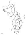
- the first embodiment of the present invention is a probe cover 1 for an ear thermometer.
- the probe cover 1 comprises a main body 11, a base 12, an open end 111, a closed end 112, a flange 113, a base plate 121, an opening 122, and protrusions 41.
- the probe cover 1 is for being mounted onto a measuring probe 21 of the ear thermometer.
- a combining mechanism 211 of the ear thermometer is disposed at the bottom of the measuring probe 21 of the ear thermometer is disposed at the bottom of the measuring probe 21 of the ear thermometer.
- the combining mechanism 211 of the ear thermometer can be formed as an annular structure.
- the combining mechanism 211 of the ear thermometer achieves the combination between the probe cover 1 and the measuring probe 21 of the ear thermometer when the probe cover 1 is mounted onto the measuring probe 21 of the ear thermometer. More particularly, the combining mechanism 211 of the ear thermometer disposed at the bottom of the measuring probe 21 of the ear thermometer can be inlaid between the opening 122 formed at the center of the base plate 121 and the protrusions 41 of the base 12 of the probe cover 1 so as to achieve the combination between the probe cover 1 and the measuring probe 21.
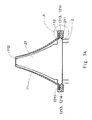
- the above-mentioned main body 11 is of a hollow structure and is made of plastic in one piece construction.
- the main body 11 has an open end 111 and a closed end 112 opposite to the open end 111 while the hollow structure of the main body 11 has a diameter gradually reducing from the open end 111 toward the closed end 112 so that the hollow structure of the main body 11 is shaped as a short truncated cone.
- the main body 11 can be made of polyethylene (PE), polypropylene (PP), polycarbonate (PC), polystyene (PS), poly ethylene terephthalate (PET) or poly vinyl chloride (PVC) where infrared rays can be transmitted through.
- the closed end 112 is a film wherethrough the measuring probe 21 of the ear thermometer receives a radiation wave (i.e. an infrared region) emitted by a human body.
- the hollow structure of the main body 11 made of plastic has a thickness decreasing gradually from the open end 111 toward the closed end 112. Therefore, the closed end 112 is the thinnest portion of the probe cover 1.
- the above-mentioned main body 11 has at least one of said flange 113 which is radially extended outward from the open end 111.
- the flange 113 can be a seamless integral flange 113 or a sectioned flange 113 with seams or intervals thereon, wherein the flange 113 formed as a seamless integral flange 113 is most preferred.
- the above-mentioned base 12 comprises a base plate 121, a guiding edge 123, and an opening 122 which is formed at a center of the base plate 121. When the main body 11 is inlaid into the base 12, the opening 122 formed at the center of the base plate 121 is positionally corresponding to the open end 111 of the main body 11.
- the base plate 121 further comprises a pair of retaining recesses 1211 and a pair of entrances 1213, wherein each entrance 1213 is disposed at one end of each retaining recess 1211.
- the pair of retaining recesses 1211 are symmetrically disposed on the base plate 121.
- the distance between one of the entrances 1213 of one of the retaining recesses 1211 to another one of the entrances 1213 of another one of the retaining recesses 1211 is smaller than the maximum diameter of the flange 113 of the main body 11, so that the flange 113 of the main body 11 can be secured at the base 12 after the flange 113 of the main body 11 enters the base 12.
- the distance between two rear ends 1214 of the retaining recesses 1211 is smaller than the distance between the pair of entrances 1213, thereby restraining the flange 113 of the inlaid main body 11 from excessively moving.
- the rear ends 1214 of the retaining recesses 1211 can be such extended that the two retaining recesses 1211 are connected mutually (as shown in Fig. 4 ), so that when the flange 113 of the main body 11 is inlaid in the base 12, the main body 11 is allowed to slightly shift its position with respect to the opening 122. Thereby, when the probe cover 1 is to be mounted onto the measuring probe 21 of the ear thermometer, since the main body 11 is allowed to slightly shift its position, the probe cover 1 can be smoothly mounted onto the measuring probe 21 of the ear thermometer.
- the above-mentioned base plate 121 of the base 12 can be further provided with at least one block 1212 for additionally restraining the flange 113 of the main body 11 from excessively moving.
- the base 12 further comprises a guiding edge 123 which directionally guides the probe cover 1 when the probe cover 1 is to be assembled into the base 12.
- the pair of retaining recesses 1211 and the base plate 121 can be integrally formed in one piece construction or can be assembled mutually, wherein it is most preferred that the pair of retaining recesses 1211 and the base plate 121 are integrally formed in one piece construction. Furthermore, the pair of retaining recesses 1211 and the base plate 121 of the base 12 can be assembled mutually via an adhesive fixing process or a heat-melting fixing process.
- a protrudent device 4 is provided on the opening 122 of the base plate 121 of the base 12.
- the protrudent device 4 is at lest two said protrusions 41.
- the diameter of the opening 122 formed at the center of the base plate 121 is smaller than the diameter of the open end 111 of the main body 11 so that when the probe cover 1 is mounted onto the measuring probe 21 of the ear thermometer, the combining mechanism 211 disposed at the bottom of the measuring probe 21 of the ear thermometer can be further inlaid between the opening 122 formed at the center of the base plate 121 and the protrusions 41 of the base 12 so as to achieve combination between the probe cover 1 and the measuring probe 21.
- the protrusions 41 can be positioned symmetrically on the base 12 or can be deposited on the base 12 with unequal distances threbetween, wherein it is most preferred that the protrusions 41 are positioned symmetrically on the base 12.
- a guiding surface 411 toward the base 12 is further provided on each said protrusion 41;
- a retaining surface 412 toward the main body 11 is further provided on each said protrusion 41.
- the guiding surface 411 and the retaining surface 412 respectively define a first included angle ⁇ 1 and a second included angle 62 with respect to an assembling direction 3, wherein the first included angle ⁇ 1 is smaller than the second included angle ⁇ 2 when the probe cover 1 is mounted onto the measuring probe 21 of the ear thermometer 2 along the assembling direction 3.
- the probe cover 1 can be mounted onto the measuring probe 21 of the ear thermometer 2 with enhanced smoothness and firmness, so as to achieve combination between the probe cover 1 and the measuring probe 21.
- the distance between the retaining surface 412 and the closed end 112 is smaller than that between the combining mechanism 211 and the end of the measuring probe 21, after the probe cover 1 is mounted onto the measuring probe 21 and when the combining mechanism 211 disposed at the bottom of the measuring probe 21 of the ear thermometer 2 abuts on the retaining surface 412, the main body 11 can be expanded and deformed because the distance between the combining mechanism 211 and the end of the measuring probe 21 is greater than that between the retaining surface 412 and the closed end 112. Consequently, the closed end 112 can present a smooth surface that allows infrared rays stably pierce therethrough in order to ensure that the ear thermometer 2 obtains measuring results with less inaccuracy.
- the present invention further provides a second embodiment.
- a probe cover 1 for an ear thermometer is provided.
- the probe cover 1 comprises a main body 11, a base 12, an open end 111, a closed end 112, a flange 113, a base plate 121, an opening 122, and a protrudent ring 42.
- a combining mechanism 211 can be formed as protrudent members or an annular shape, whereby a measuring probe 21 of an ear thermometer can be inlaid between the opening 122 formed at the center of the base plate 121 and the protrudent ring 42 of the base 12 of the probe cover 1 so as to achieve combination between the probe cover 1 and the measuring probe 21.
- Other characteristics of the probe cover 1 are substantially the same as those disclosed in the first embodiment.
- the present invention further provides a third embodiment related to a manufacturing method for the probe cover 1 according to the first embodiment.
- the disclosed method comprises: (1) providing a main body 11, which is integrally made of plastic in one piece construction and has at least one flange 113 extended radially from an open end 111 of the main body 11; and (2) providing a base 12, which comprises a base plate 121 and an opening 122 formed at the center of the base plate 121, wherein the opening 122 is positionally corresponding to the open end 111 of the main body 11 and the base 12 is formed with at least one entrance 1213 for allowing the flange 113 of the main body 11 to be inlaid in the base 12.
- the combining mechanism 211 provided at a bottom of a measuring probe 21 of the ear thermometer is of an annular structure (referring to Fig. 2A ) whereby the combining mechanism 211 can restrain the measuring probe 21 of the ear thermometer between the opening 122 formed at the center of the base plate 121 and protrusions 41 of the base 12 of the probe cover 1 so as to achieve combination between the probe cover 1 and the measuring probe 21 of the ear thermometer.
- Other characteristics of the probe cover 1 are substantially the same as those disclosed in the first embodiment.
- the present invention further provides a fourth embodiment related to a manufacturing method for another probe cover 1 according to the second embodiment.
- the disclosed method comprises: (1) providing a main body 11, which is integrally made of plastic in one piece construction and has at least one flange 113 extended radially from an open end 111 of the main body 11; and (2) providing a base 12, which comprises a base plate 121 and an opening 122 formed at the center of the base plate 121, wherein the opening 122 is positionally corresponding to the open end 111 of the main body 11 and the base 12 is formed with at least one entrance 1213 for allowing the flange 113 of the main body 11 to be inlaid in the base 12.
- a combining mechanism 211 provided at a bottom of a measuring probe of the ear thermometer is formed as protrudent members (referring to Fig. 2B ) or of an annular structure (referring to Fig. 2A ) whereby the measuring probe 21 of the ear thermometer can be inlaid between the opening 122 formed at the center of the base plate 121 and a protrudent ring 42 of the base 12 of the probe cover 1 so as to achieve combination between the probe cover 1 and the measuring probe 21 of the ear thermometer.
- Other characteristics of the probe cover 1 are substantially the same as those disclosed in the first embodiment.
Claims (7)
- Abnehmbare Sensorabdeckung (1) für ein Ohrthermometer (2), die auf einen Messsensor des Oberthermometers befestigt wird und die einen Hauptkörper (11) mit hohler Struktur und eine Basis (12) umfasst, wobei der Hauptkörper (11) ein offenes Ende (111) und ein geschlossenes Ende (112) gegenüber dem offenen Ende (111) umfasst und wobei die hohle Struktur des Hauptkörpers (11) einen Durchmesser aufweist, der sich allmählich vom offenen Ende (111) zum geschlossen Ende (112) hin verringert, dadurch gekennzeichnet, dass: der Hauptkörper (11) einstückig aus Kunststoff hergestellt ist und wenigstens einen Flansch (113) umfasst, der sich radial nach außen von dem offenen Ende (111) erstreckt, wobei die hohle Struktur des Körpers (11) als ein kurzer abgeschnittener Kegel ausgebildet ist und eine Dicke des Kunststoffes aufweist, die sich allmählich von dem offenen Ende (111) zu dem geschlossen Ende (112) hin verringert, so dass das geschlossene Ende (112) der kleinste Teil der abnehmbaren Sensorabdeckung (1) ist, die Basis (12) eine Basisplatte (121), einen Führungsrand (123) und eine in der Mitte der Basisplatte (121) ausgebildete Öffnung (122) umfasst, wobei die Öffnung (122) dem offenen Ende (111) des Hauptkörpers (11) entspricht, wenn der Hauptkörper (11) in die Basis (12) eingeschoben ist, und
die Basisplatte (121) ein Paar Halteausnehmungen (1211) umfasst, wobei ein Eingang (1213) an einem Ende jeder Halteausnehmung (1211) ausgebildet ist, wobei das Paar Halteausnehmungen (1211) symmetrisch auf der Basisplatte (121) angeordnet ist, so dass der Flansch (113) in die Basis (12) durch die Eingänge (1213) eingeführt und eingeschoben werden kann, wobei, nachdem der Flansch (113) des Hauptkörpers (11) in die Basis (12) eingeschoben ist, es dem Hauptkörper (11) möglich ist, in der Position in Bezug auf die Öffnung (122) der Basisplatte (121) ein wenig zu verrutschen, so dass, wenn die abnehmbare Sensorabdeckung auf den Messsensor eines Ohrthermometer befestigt werden soll, die abnehmbare Sensorabdeckungen (1) leichtgängig auf der Messsonde des Ohrthermometers befestigt werden kann, da der Hauptkörper ein wenig rutschen kann. - Abnehmbare Sensorabdeckung (1) nach Anspruch 1, wobei der Abstand zwischen dem Paar von Eingängen (1213) kleiner ist als der maximale Durchmesser des Flansches (113) des Hauptkörpers (11) und wobei die Distanz zwischen den zwei hinteren Enden (1214) der Halteausnehmungen (1211) kleiner ist als die Distanz zwischen dem Paar von Eingängen (1213), so dass der Flansch (113) des eingeschobenen Hauptkörpers (11) davon abgehalten wird, sich zu bewegen.
- Abnehmbare Sensorabdeckung (1) nach Anspruch 1, wobei die Basisplatte (121) der Basis (12) an ihrer Öffnung (122) mit einer vorstehenden Vorrichtung (4) versehen ist, wobei die vorstehende Vorrichtung (4) wenigstens zwei Vorsprünge (41) umfasst, wobei diese symmetrisch auf der Basis (12) angeordnet sind oder mit unterschiedlichen Abständen untereinander auf der Basis angeordnet sind.
- Abnehmbare Sensorabdeckung (1) nach Anspruch 1, wobei die Basisplatte (121) der Basis (12) an ihrer Öffnung (132) mit einer vorstehenden Vorrichtung (4) versehen ist, wobei die vorstehende Vorrichtung (4) wenigstens einen vorstehenden Ring (42) umfasst.
- Abnehmbare Sensorabdeckung (1) nach Anspruch 3 oder 4, wobei die vorstehende Vorrichtung (4) mit einer Führungsfläche (411) in Richtung der Basis (12) und einer Rückhaltefläche (412) in Richtung des Hauptkörpers (11) versehen ist, wobei die Führungsfläche (411) und die Rückhaltefläche (412) entsprechend einen ersten eingeschlossenen Winkel (θ1) und einen zweiten eingeschlossenen Winkel (θ2) in Bezug auf die Anordnungsausrichtung (3) definieren, wobei der erste eingeschlossene Winkel (θ1) kleiner ist als der zweite eingeschlossene Winkel (θ2).
- Abnehmbare Sensorabdeckungen (1) nach Anspruch 1, wobei der Durchmesser der in der Mitte der Basis (12) ausgebildeten Öffnung (122) kleiner ist als der Durchmesser des offenen Endes (111) des Hauptkörpers (11).
- Abnehmbare Sensorabdeckung (1) nach Anspruch 1, wobei der Hauptkörper (11) aus einem Material hergestellt ist, das aus der Gruppe ausgewählt wurde, die Polyethylen (PE), Polypropylen (PP), Polycarbonat (PC), Polystyrol (PS), Polyethylenterephthalat (PET) und Polyvinylchlorid (PVC) umfasst, so dass Infrarotstrahlen transmittieren können.
Applications Claiming Priority (1)
| Application Number | Priority Date | Filing Date | Title |
|---|---|---|---|
| TW096142339A TW200921063A (en) | 2007-11-09 | 2007-11-09 | Probe cover for ear thermometer and manufacturing method thereof |
Publications (2)
| Publication Number | Publication Date |
|---|---|
| EP2060889A1 EP2060889A1 (de) | 2009-05-20 |
| EP2060889B1 true EP2060889B1 (de) | 2012-01-04 |
Family
ID=40279032
Family Applications (1)
| Application Number | Title | Priority Date | Filing Date |
|---|---|---|---|
| EP08159569A Not-in-force EP2060889B1 (de) | 2007-11-09 | 2008-07-03 | Abnehmbare Sondenabdeckung für ein Ohrthermometer und Herstellungsverfahren dafür |
Country Status (6)
| Country | Link |
|---|---|
| US (1) | US8092082B2 (de) |
| EP (1) | EP2060889B1 (de) |
| JP (1) | JP4665010B2 (de) |
| AT (1) | ATE540293T1 (de) |
| ES (1) | ES2379953T3 (de) |
| TW (1) | TW200921063A (de) |
Families Citing this family (4)
| Publication number | Priority date | Publication date | Assignee | Title |
|---|---|---|---|---|
| USD787683S1 (en) | 2009-04-09 | 2017-05-23 | Welch Allyn, Inc. | Cover for a probe |
| US8996096B2 (en) | 2011-07-19 | 2015-03-31 | Welch Allyn, Inc. | Systems and methods for determining patient temperature |
| EP3078951A1 (de) | 2015-04-10 | 2016-10-12 | Silverlight AG | Einrichtung mit pir sensor |
| CN108714025A (zh) * | 2018-04-10 | 2018-10-30 | 浙江智柔科技有限公司 | 生理信号测量装置用护套 |
Family Cites Families (20)
| Publication number | Priority date | Publication date | Assignee | Title |
|---|---|---|---|---|
| US3987899A (en) * | 1975-04-25 | 1976-10-26 | Edwin L. Spangler, Jr. | Disposable thermometer cap and method of making same |
| US5163418A (en) * | 1989-09-19 | 1992-11-17 | Thermoscan Inc. | Speculum cover |
| EP0674162B1 (de) * | 1990-03-08 | 2002-01-02 | Alaris Medical Systems, Inc. | Thermisch isolierte Sonde |
| US5088834A (en) * | 1990-08-24 | 1992-02-18 | Thermoscan Inc. | Unitary probe cover |
| US5411032A (en) | 1993-06-18 | 1995-05-02 | Infra-Temp Inc. | Electronic thermometer probe cover |
| TW410272B (en) * | 1996-05-07 | 2000-11-01 | Thermoscan Lnc | Enhanced protective lens cover |
| US5906437A (en) * | 1997-06-10 | 1999-05-25 | Oriental System Technology Inc. | Probe cover for a tympanic thermometer |
| US6224256B1 (en) * | 1998-06-18 | 2001-05-01 | Harry Bala | Cover for medical probe |
| JP2001078967A (ja) * | 1999-09-09 | 2001-03-27 | Kazuhito Sakano | プローブカバー及びそれを装着する耳式体温計のプローブ並びにそれらの着脱構造 |
| US6371639B1 (en) * | 2000-10-13 | 2002-04-16 | Radiant Innovation Inc. | Probe cover of a tympanic thermometer and method for manufacturing the same |
| US6619837B2 (en) * | 2001-05-17 | 2003-09-16 | Sherwood Services Ag | Probe cover with lubrication well |
| JP3945189B2 (ja) | 2001-06-01 | 2007-07-18 | オムロンヘルスケア株式会社 | 赤外線体温計 |
| JP4049243B2 (ja) * | 2001-12-28 | 2008-02-20 | 株式会社エー・アンド・デイ | 耳式体温計用プローブカバー |
| TW538238B (en) * | 2002-09-16 | 2003-06-21 | Oriental System Technology Inc | Probe cover and assembly of ear clinical thermometer |
| CN100422704C (zh) | 2003-01-06 | 2008-10-01 | 舍伍德服务公开股份有限公司 | 带有弹出机构的鼓膜体温计 |
| US7399275B2 (en) * | 2003-07-28 | 2008-07-15 | Welch Allyn, Inc. | Otoscope |
| US7354399B2 (en) * | 2003-07-28 | 2008-04-08 | Welch Allyn, Inc. | Otoscopic tip element and related method of use |
| DE10336436A1 (de) | 2003-08-08 | 2005-03-17 | Braun Gmbh | Einweg-Schutzkappe und Infrarot-Thermometer |
| WO2010078219A1 (en) * | 2008-12-29 | 2010-07-08 | Kaz Europe Sa | Probe cover with matching feature for a medical thermometer |
| US8374683B2 (en) * | 2009-12-30 | 2013-02-12 | Ray D. Stone | Medical instrument with probe, probe cover, and methods of using the same |
-
2007
- 2007-11-09 TW TW096142339A patent/TW200921063A/zh unknown
-
2008
- 2008-04-01 JP JP2008094778A patent/JP4665010B2/ja not_active Expired - Fee Related
- 2008-05-07 US US12/116,304 patent/US8092082B2/en not_active Expired - Fee Related
- 2008-07-03 EP EP08159569A patent/EP2060889B1/de not_active Not-in-force
- 2008-07-03 ES ES08159569T patent/ES2379953T3/es active Active
- 2008-07-03 AT AT08159569T patent/ATE540293T1/de active
Also Published As
| Publication number | Publication date |
|---|---|
| EP2060889A1 (de) | 2009-05-20 |
| ES2379953T3 (es) | 2012-05-07 |
| ATE540293T1 (de) | 2012-01-15 |
| JP2009119237A (ja) | 2009-06-04 |
| US20090122835A1 (en) | 2009-05-14 |
| JP4665010B2 (ja) | 2011-04-06 |
| TW200921063A (en) | 2009-05-16 |
| US8092082B2 (en) | 2012-01-10 |
Similar Documents
| Publication | Publication Date | Title |
|---|---|---|
| CN100539938C (zh) | 带有薄膜支撑结构的鼓膜体温计探头盖 | |
| KR100322107B1 (ko) | 이어 타입 체온계 | |
| US7585108B2 (en) | Probe cover for ear thermometer and manufacturing method thereof | |
| US8136986B2 (en) | Disposable speculum for medical thermometer | |
| EP2060889B1 (de) | Abnehmbare Sondenabdeckung für ein Ohrthermometer und Herstellungsverfahren dafür | |
| US6030117A (en) | Tympanic thermometer probe cover | |
| JP2004105733A (ja) | 鼓膜温度計のプローブカバーおよび鼓膜温度計アセンブリ | |
| US8657491B2 (en) | Detachable probe cover for ear thermometer and manufacturing method thereof | |
| US7722250B2 (en) | Probe cover for ear thermometer | |
| JPH1137853A (ja) | 体温計用プローブカバー | |
| JPH0856909A (ja) | 体温計 | |
| US20030043884A1 (en) | Probe cover of ear thermometer | |
| JP2003126048A (ja) | 体温計及びその体温計のセンサキャップ | |
| JP3613035B2 (ja) | プローブカバー | |
| JP2000227361A (ja) | 赤外線体温計 | |
| JP2003061915A (ja) | 耳式体温計 |
Legal Events
| Date | Code | Title | Description |
|---|---|---|---|
| PUAI | Public reference made under article 153(3) epc to a published international application that has entered the european phase |
Free format text: ORIGINAL CODE: 0009012 |
|
| 17P | Request for examination filed |
Effective date: 20081211 |
|
| AK | Designated contracting states |
Kind code of ref document: A1 Designated state(s): AT BE BG CH CY CZ DE DK EE ES FI FR GB GR HR HU IE IS IT LI LT LU LV MC MT NL NO PL PT RO SE SI SK TR |
|
| AX | Request for extension of the european patent |
Extension state: AL BA MK RS |
|
| 17Q | First examination report despatched |
Effective date: 20091124 |
|
| AKX | Designation fees paid | ||
| RBV | Designated contracting states (corrected) |
Designated state(s): AT BE BG CH CY CZ DE DK EE ES FI FR GB GR HR HU IE IS IT LI LT LU LV MC MT NL NO PL PT RO SE SI SK TR |
|
| GRAP | Despatch of communication of intention to grant a patent |
Free format text: ORIGINAL CODE: EPIDOSNIGR1 |
|
| GRAS | Grant fee paid |
Free format text: ORIGINAL CODE: EPIDOSNIGR3 |
|
| GRAA | (expected) grant |
Free format text: ORIGINAL CODE: 0009210 |
|
| AK | Designated contracting states |
Kind code of ref document: B1 Designated state(s): AT BE BG CH CY CZ DE DK EE ES FI FR GB GR HR HU IE IS IT LI LT LU LV MC MT NL NO PL PT RO SE SI SK TR |
|
| REG | Reference to a national code |
Ref country code: GB Ref legal event code: FG4D |
|
| REG | Reference to a national code |
Ref country code: CH Ref legal event code: EP |
|
| REG | Reference to a national code |
Ref country code: AT Ref legal event code: REF Ref document number: 540293 Country of ref document: AT Kind code of ref document: T Effective date: 20120115 |
|
| REG | Reference to a national code |
Ref country code: IE Ref legal event code: FG4D |
|
| REG | Reference to a national code |
Ref country code: DE Ref legal event code: R096 Ref document number: 602008012453 Country of ref document: DE Effective date: 20120301 |
|
| REG | Reference to a national code |
Ref country code: NL Ref legal event code: VDEP Effective date: 20120104 |
|
| REG | Reference to a national code |
Ref country code: ES Ref legal event code: FG2A Ref document number: 2379953 Country of ref document: ES Kind code of ref document: T3 Effective date: 20120507 |
|
| PG25 | Lapsed in a contracting state [announced via postgrant information from national office to epo] |
Ref country code: SI Free format text: LAPSE BECAUSE OF FAILURE TO SUBMIT A TRANSLATION OF THE DESCRIPTION OR TO PAY THE FEE WITHIN THE PRESCRIBED TIME-LIMIT Effective date: 20120104 |
|
| LTIE | Lt: invalidation of european patent or patent extension |
Effective date: 20120104 |
|
| PG25 | Lapsed in a contracting state [announced via postgrant information from national office to epo] |
Ref country code: IS Free format text: LAPSE BECAUSE OF FAILURE TO SUBMIT A TRANSLATION OF THE DESCRIPTION OR TO PAY THE FEE WITHIN THE PRESCRIBED TIME-LIMIT Effective date: 20120504 Ref country code: NO Free format text: LAPSE BECAUSE OF FAILURE TO SUBMIT A TRANSLATION OF THE DESCRIPTION OR TO PAY THE FEE WITHIN THE PRESCRIBED TIME-LIMIT Effective date: 20120404 Ref country code: LT Free format text: LAPSE BECAUSE OF FAILURE TO SUBMIT A TRANSLATION OF THE DESCRIPTION OR TO PAY THE FEE WITHIN THE PRESCRIBED TIME-LIMIT Effective date: 20120104 Ref country code: BE Free format text: LAPSE BECAUSE OF FAILURE TO SUBMIT A TRANSLATION OF THE DESCRIPTION OR TO PAY THE FEE WITHIN THE PRESCRIBED TIME-LIMIT Effective date: 20120104 Ref country code: BG Free format text: LAPSE BECAUSE OF FAILURE TO SUBMIT A TRANSLATION OF THE DESCRIPTION OR TO PAY THE FEE WITHIN THE PRESCRIBED TIME-LIMIT Effective date: 20120404 Ref country code: HR Free format text: LAPSE BECAUSE OF FAILURE TO SUBMIT A TRANSLATION OF THE DESCRIPTION OR TO PAY THE FEE WITHIN THE PRESCRIBED TIME-LIMIT Effective date: 20120104 Ref country code: NL Free format text: LAPSE BECAUSE OF FAILURE TO SUBMIT A TRANSLATION OF THE DESCRIPTION OR TO PAY THE FEE WITHIN THE PRESCRIBED TIME-LIMIT Effective date: 20120104 |
|
| PG25 | Lapsed in a contracting state [announced via postgrant information from national office to epo] |
Ref country code: LV Free format text: LAPSE BECAUSE OF FAILURE TO SUBMIT A TRANSLATION OF THE DESCRIPTION OR TO PAY THE FEE WITHIN THE PRESCRIBED TIME-LIMIT Effective date: 20120104 Ref country code: FI Free format text: LAPSE BECAUSE OF FAILURE TO SUBMIT A TRANSLATION OF THE DESCRIPTION OR TO PAY THE FEE WITHIN THE PRESCRIBED TIME-LIMIT Effective date: 20120104 Ref country code: PT Free format text: LAPSE BECAUSE OF FAILURE TO SUBMIT A TRANSLATION OF THE DESCRIPTION OR TO PAY THE FEE WITHIN THE PRESCRIBED TIME-LIMIT Effective date: 20120504 Ref country code: PL Free format text: LAPSE BECAUSE OF FAILURE TO SUBMIT A TRANSLATION OF THE DESCRIPTION OR TO PAY THE FEE WITHIN THE PRESCRIBED TIME-LIMIT Effective date: 20120104 Ref country code: GR Free format text: LAPSE BECAUSE OF FAILURE TO SUBMIT A TRANSLATION OF THE DESCRIPTION OR TO PAY THE FEE WITHIN THE PRESCRIBED TIME-LIMIT Effective date: 20120405 |
|
| REG | Reference to a national code |
Ref country code: AT Ref legal event code: MK05 Ref document number: 540293 Country of ref document: AT Kind code of ref document: T Effective date: 20120104 |
|
| PG25 | Lapsed in a contracting state [announced via postgrant information from national office to epo] |
Ref country code: CY Free format text: LAPSE BECAUSE OF FAILURE TO SUBMIT A TRANSLATION OF THE DESCRIPTION OR TO PAY THE FEE WITHIN THE PRESCRIBED TIME-LIMIT Effective date: 20120104 |
|
| PG25 | Lapsed in a contracting state [announced via postgrant information from national office to epo] |
Ref country code: RO Free format text: LAPSE BECAUSE OF FAILURE TO SUBMIT A TRANSLATION OF THE DESCRIPTION OR TO PAY THE FEE WITHIN THE PRESCRIBED TIME-LIMIT Effective date: 20120104 Ref country code: CZ Free format text: LAPSE BECAUSE OF FAILURE TO SUBMIT A TRANSLATION OF THE DESCRIPTION OR TO PAY THE FEE WITHIN THE PRESCRIBED TIME-LIMIT Effective date: 20120104 Ref country code: SE Free format text: LAPSE BECAUSE OF FAILURE TO SUBMIT A TRANSLATION OF THE DESCRIPTION OR TO PAY THE FEE WITHIN THE PRESCRIBED TIME-LIMIT Effective date: 20120104 Ref country code: DK Free format text: LAPSE BECAUSE OF FAILURE TO SUBMIT A TRANSLATION OF THE DESCRIPTION OR TO PAY THE FEE WITHIN THE PRESCRIBED TIME-LIMIT Effective date: 20120104 Ref country code: EE Free format text: LAPSE BECAUSE OF FAILURE TO SUBMIT A TRANSLATION OF THE DESCRIPTION OR TO PAY THE FEE WITHIN THE PRESCRIBED TIME-LIMIT Effective date: 20120104 |
|
| PLBE | No opposition filed within time limit |
Free format text: ORIGINAL CODE: 0009261 |
|
| STAA | Information on the status of an ep patent application or granted ep patent |
Free format text: STATUS: NO OPPOSITION FILED WITHIN TIME LIMIT |
|
| PG25 | Lapsed in a contracting state [announced via postgrant information from national office to epo] |
Ref country code: SK Free format text: LAPSE BECAUSE OF FAILURE TO SUBMIT A TRANSLATION OF THE DESCRIPTION OR TO PAY THE FEE WITHIN THE PRESCRIBED TIME-LIMIT Effective date: 20120104 |
|
| 26N | No opposition filed |
Effective date: 20121005 |
|
| PG25 | Lapsed in a contracting state [announced via postgrant information from national office to epo] |
Ref country code: AT Free format text: LAPSE BECAUSE OF FAILURE TO SUBMIT A TRANSLATION OF THE DESCRIPTION OR TO PAY THE FEE WITHIN THE PRESCRIBED TIME-LIMIT Effective date: 20120104 |
|
| REG | Reference to a national code |
Ref country code: DE Ref legal event code: R097 Ref document number: 602008012453 Country of ref document: DE Effective date: 20121005 |
|
| PG25 | Lapsed in a contracting state [announced via postgrant information from national office to epo] |
Ref country code: MC Free format text: LAPSE BECAUSE OF NON-PAYMENT OF DUE FEES Effective date: 20120731 |
|
| REG | Reference to a national code |
Ref country code: CH Ref legal event code: PL |
|
| PG25 | Lapsed in a contracting state [announced via postgrant information from national office to epo] |
Ref country code: LI Free format text: LAPSE BECAUSE OF NON-PAYMENT OF DUE FEES Effective date: 20120731 Ref country code: CH Free format text: LAPSE BECAUSE OF NON-PAYMENT OF DUE FEES Effective date: 20120731 |
|
| REG | Reference to a national code |
Ref country code: DE Ref legal event code: R082 Ref document number: 602008012453 Country of ref document: DE Representative=s name: LANGPATENT ANWALTSKANZLEI IP LAW FIRM, DE |
|
| REG | Reference to a national code |
Ref country code: IE Ref legal event code: MM4A |
|
| PG25 | Lapsed in a contracting state [announced via postgrant information from national office to epo] |
Ref country code: MT Free format text: LAPSE BECAUSE OF FAILURE TO SUBMIT A TRANSLATION OF THE DESCRIPTION OR TO PAY THE FEE WITHIN THE PRESCRIBED TIME-LIMIT Effective date: 20120104 Ref country code: IE Free format text: LAPSE BECAUSE OF NON-PAYMENT OF DUE FEES Effective date: 20120703 |
|
| PGFP | Annual fee paid to national office [announced via postgrant information from national office to epo] |
Ref country code: ES Payment date: 20130726 Year of fee payment: 6 Ref country code: DE Payment date: 20130729 Year of fee payment: 6 |
|
| PGFP | Annual fee paid to national office [announced via postgrant information from national office to epo] |
Ref country code: GB Payment date: 20130729 Year of fee payment: 6 Ref country code: FR Payment date: 20130717 Year of fee payment: 6 |
|
| PGFP | Annual fee paid to national office [announced via postgrant information from national office to epo] |
Ref country code: IT Payment date: 20130722 Year of fee payment: 6 |
|
| PG25 | Lapsed in a contracting state [announced via postgrant information from national office to epo] |
Ref country code: TR Free format text: LAPSE BECAUSE OF FAILURE TO SUBMIT A TRANSLATION OF THE DESCRIPTION OR TO PAY THE FEE WITHIN THE PRESCRIBED TIME-LIMIT Effective date: 20120104 |
|
| PG25 | Lapsed in a contracting state [announced via postgrant information from national office to epo] |
Ref country code: LU Free format text: LAPSE BECAUSE OF NON-PAYMENT OF DUE FEES Effective date: 20120703 |
|
| PG25 | Lapsed in a contracting state [announced via postgrant information from national office to epo] |
Ref country code: HU Free format text: LAPSE BECAUSE OF FAILURE TO SUBMIT A TRANSLATION OF THE DESCRIPTION OR TO PAY THE FEE WITHIN THE PRESCRIBED TIME-LIMIT Effective date: 20080703 |
|
| REG | Reference to a national code |
Ref country code: DE Ref legal event code: R119 Ref document number: 602008012453 Country of ref document: DE |
|
| GBPC | Gb: european patent ceased through non-payment of renewal fee |
Effective date: 20140703 |
|
| REG | Reference to a national code |
Ref country code: DE Ref legal event code: R119 Ref document number: 602008012453 Country of ref document: DE Effective date: 20150203 |
|
| REG | Reference to a national code |
Ref country code: FR Ref legal event code: ST Effective date: 20150331 |
|
| PG25 | Lapsed in a contracting state [announced via postgrant information from national office to epo] |
Ref country code: DE Free format text: LAPSE BECAUSE OF NON-PAYMENT OF DUE FEES Effective date: 20150203 Ref country code: IT Free format text: LAPSE BECAUSE OF NON-PAYMENT OF DUE FEES Effective date: 20140703 |
|
| PG25 | Lapsed in a contracting state [announced via postgrant information from national office to epo] |
Ref country code: FR Free format text: LAPSE BECAUSE OF NON-PAYMENT OF DUE FEES Effective date: 20140731 Ref country code: GB Free format text: LAPSE BECAUSE OF NON-PAYMENT OF DUE FEES Effective date: 20140703 |
|
| REG | Reference to a national code |
Ref country code: ES Ref legal event code: FD2A Effective date: 20150929 |
|
| PG25 | Lapsed in a contracting state [announced via postgrant information from national office to epo] |
Ref country code: ES Free format text: LAPSE BECAUSE OF NON-PAYMENT OF DUE FEES Effective date: 20140704 |