EP2060834A1 - Oil seal for reciprocation motion - Google Patents
Oil seal for reciprocation motion Download PDFInfo
- Publication number
- EP2060834A1 EP2060834A1 EP07806645A EP07806645A EP2060834A1 EP 2060834 A1 EP2060834 A1 EP 2060834A1 EP 07806645 A EP07806645 A EP 07806645A EP 07806645 A EP07806645 A EP 07806645A EP 2060834 A1 EP2060834 A1 EP 2060834A1
- Authority
- EP
- European Patent Office
- Prior art keywords
- seal
- backup ring
- peripheral surface
- inner peripheral
- reciprocation motion
- Prior art date
- Legal status (The legal status is an assumption and is not a legal conclusion. Google has not performed a legal analysis and makes no representation as to the accuracy of the status listed.)
- Granted
Links
Images

Classifications
-
- F—MECHANICAL ENGINEERING; LIGHTING; HEATING; WEAPONS; BLASTING
- F16—ENGINEERING ELEMENTS AND UNITS; GENERAL MEASURES FOR PRODUCING AND MAINTAINING EFFECTIVE FUNCTIONING OF MACHINES OR INSTALLATIONS; THERMAL INSULATION IN GENERAL
- F16J—PISTONS; CYLINDERS; SEALINGS
- F16J15/00—Sealings
- F16J15/16—Sealings between relatively-moving surfaces
- F16J15/32—Sealings between relatively-moving surfaces with elastic sealings, e.g. O-rings
- F16J15/3204—Sealings between relatively-moving surfaces with elastic sealings, e.g. O-rings with at least one lip
- F16J15/3216—Sealings between relatively-moving surfaces with elastic sealings, e.g. O-rings with at least one lip supported in a direction parallel to the surfaces
-
- F—MECHANICAL ENGINEERING; LIGHTING; HEATING; WEAPONS; BLASTING
- F16—ENGINEERING ELEMENTS AND UNITS; GENERAL MEASURES FOR PRODUCING AND MAINTAINING EFFECTIVE FUNCTIONING OF MACHINES OR INSTALLATIONS; THERMAL INSULATION IN GENERAL
- F16J—PISTONS; CYLINDERS; SEALINGS
- F16J15/00—Sealings
- F16J15/16—Sealings between relatively-moving surfaces
- F16J15/32—Sealings between relatively-moving surfaces with elastic sealings, e.g. O-rings
- F16J15/3204—Sealings between relatively-moving surfaces with elastic sealings, e.g. O-rings with at least one lip
- F16J15/322—Sealings between relatively-moving surfaces with elastic sealings, e.g. O-rings with at least one lip supported in a direction perpendicular to the surfaces
-
- F—MECHANICAL ENGINEERING; LIGHTING; HEATING; WEAPONS; BLASTING
- F16—ENGINEERING ELEMENTS AND UNITS; GENERAL MEASURES FOR PRODUCING AND MAINTAINING EFFECTIVE FUNCTIONING OF MACHINES OR INSTALLATIONS; THERMAL INSULATION IN GENERAL
- F16J—PISTONS; CYLINDERS; SEALINGS
- F16J15/00—Sealings
- F16J15/56—Other sealings for reciprocating rods
Definitions
- the present invention relates to an oil seal for reciprocation motion.
- the present invention relates to an oil seal for reciprocation motion including a backup ring that is suitable for ensuring durability of a seal lip.
- an oil seal for reciprocation motion that includes a resin backup ring, made of fluorocarbon resin and the like, to ensure durability of a seal lip.
- the backup ring is disposed such as to support a seal surface of the seal lip.
- an oil seal for reciprocation motion such as this, an oil seal for reciprocation motion is known in which an annular groove that can hold a lubricating agent is provided on an inner peripheral surface of the backup ring that extends in parallel with a reciprocating shaft in a setting state in which the oil seal for reciprocation motion is mounted in a sealed location.
- Patent Literature 1 Japanese Unexamined Utility Model Application Publication No. Showa 60-110767 ( Fig. 1 and Fig. 3 )
- the inner peripheral surface of the resin backup ring is disposed parallel with an outer peripheral surface of the reciprocating shaft. Therefore, when the oil seal is used under high pressure, such as pressure of 2MPa to 9MPa on the sealed side, the inner peripheral surface of the backup ring comes into contact with the reciprocating shaft over its entire surface. The annular groove is crushed by the pressure and can no longer hold the lubricating agent.
- an oil seal for reciprocation motion is required that can achieve high performance with certainty, by preventing the inner peripheral surface of the backup ring from coming into contact with the reciprocating shaft over its entire surface, even when used under high pressure.
- An object of the present invention is to provide an oil seal for reciprocation motion that can achieve high performance with certainty by preventing an inner peripheral surface of a backup ring from coming into contact with a reciprocating shaft over its entire surface.
- an oil seal for reciprocation motion of the present invention includes a seal main body including a seal lip that can be in sliding contact with a reciprocating shaft.
- the oil seal for reciprocation motion also includes a backup ring made of resin that is disposed such as to support the seal lip from an atmosphere side to ensure durability of the seal lip.
- a backup ring made of resin that is disposed such as to support the seal lip from an atmosphere side to ensure durability of the seal lip.
- the annular groove can hold a lubricating material.
- the oil seal for reciprocation motion also includes a holding member that holds the backup ring between the holding member and the seal main body in a sandwiched-state.
- the inner peripheral surface of the backup ring forms a taper that increases in diameter from a sealed side to the atmosphere side along an axial direction.
- Another oil seal for reciprocation motion of the present invention includes a seal main body including a seal lip that can be in sliding contact with a reciprocating shaft.
- the oil seal for reciprocation motion also includes a backup ring made of resin that is disposed such as to support the seal lip from an atmosphere side to ensure durability of the seal lip.
- a backup ring made of resin that is disposed such as to support the seal lip from an atmosphere side to ensure durability of the seal lip.
- the annular groove can hold a lubricating material.
- the oil seal for reciprocation motion also includes a holding member that holds the backup ring between the holding member and the seal main body in a sandwiched-state.
- a plurality of annular projections are arrayed on the inner peripheral surface of the backup ring along an axial direction.
- the annular groove is formed by a valley between each annular projection and an adjacent annular projection.
- a virtual inner peripheral surface formed by a bus linearly connecting peak sections of the annular projections along the axial direction forms a taper that increases in diameter from a sealed side towards the atmosphere side in the axial direction.
- An angle of the taper is preferably 1 to 15 degrees. Peak angles of the annular projections are preferably 120 to 160 degrees.
- the oil seal for reciprocation motion preferably includes a main seal including the seal main body and disposed on the sealed side, and a dust seal disposed on the atmosphere side of the main seal.
- the dust seal preferably configures the holding member.
- the inner peripheral surface of the backup ring that forms a taper can maintain a non-contact state with the reciprocating shaft in at least an area of the inner peripheral surface of the backup ring on the atmosphere side. Therefore, the annular groove can be prevented from becoming crushed by the pressure. As a result, advantageous effects can be achieved, such as high performance being achieved with certainty by the inner peripheral surface of the backup ring being prevented from coming into contact with the reciprocating shaft over its entire surface.
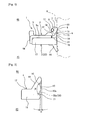
- Fig. 1 and Fig. 2 are diagrams of an oil seal for reciprocation motion according to a first embodiment of the present invention.
- Fig. 1 is a cross-sectional view of main components.
- Fig. 2 is an enlarged cross-sectional view of a backup ring in Fig. 1 .
- the oil seal for reciprocation motion according to the first embodiment is provided with a plurality of annular projections on an inner surface of a backup ring.
- the oil seal for reciprocation motion according to the first embodiment is used in a shock absorber (hydraulic draft gear) of a suspension device used in a vehicle, such as an automobile and a two-wheeled vehicle.
- an oil seal 1 for reciprocation motion includes a main seal 2, a dust seal 3, and a backup ring 4.
- the main seal 2 is disposed on a sealed side OS.
- the dust seal 3 is disposed on an atmosphere side AS.
- the backup ring 4 is disposed between the main seal 2 and the dust seal 3.
- the main seal 2 prevents a sealing fluid (not shown), such as a lubricating oil, from leaking from the sealed side OS, indicated on the upper side in Fig. 1 , to the atmosphere side AS, indicated on the lower side in Fig. 1 .
- the main seal 2 is formed by a seal main body 6 being integrally burned onto a main reinforcing ring 5.
- the main reinforcing ring 5 serves as a reinforcing ring and is made of a rigid material, such as metal.
- the seal main body 6 is made of a rubber-like, elastic body.
- the main reinforcement ring 5 is formed by an annular ring main body 5a and an outer section 5b such as to have an overall ring shape, of which a cross-section forms an almost lateral L-shape.
- the outer section 5b extends in an almost perpendicular manner from an outer peripheral edge of the ring main body 5a towards the atmosphere side AS, indicated on the lower side in Fig. 1 .
- An annular seal lip 7 is formed on the seal main body 6 such as to become gradually smaller in diameter from an inner peripheral section of the main reinforcing ring 5 towards the sealed side OS.
- the seal lip 7 has an appropriate amount of interference with a reciprocating shaft 8, indicated by a two-dot chain line in Fig. 1 .
- the seal lip 7 includes a lip tip 9 that is in sliding contact with the reciprocating shaft 8.
- the seal lip 7 also includes an oil surface 10 and a seal surface 11.
- the oil surface 10 has a predetermined oil surface angle allowing an increase in diameter from the lip tip 9 towards the sealed side OS.
- the seal surface 11 has a predetermined seal angle allowing an increase in diameter from the lip tip 9 towards the atmosphere side AS.
- a predetermined area of the seal surface 11 on the lip tip 9 side comes into contact with a front surface of the reciprocating shaft 8, with an appropriate amount of interference therebetween.
- a garter spring 12 is disposed on a back surface of the seal lip 7 on an outward radial direction of the lip tip 9. The garter spring 12 is provided to maintain tension between the seal lip 7 and the reciprocating shaft 8 in a radial direction.
- the dust seal 3 is provided to prevent dust, such as dirt and debris, from the atmosphere side AS from infiltrating the sealed side OS.
- the dust seal 3 is formed by an annular dust lip 14 being integrally burned onto a dust reinforcing ring 13.
- the dust reinforcing ring 13 serves as a reinforcing ring and is made of a rigid material, such as metal.
- the dust lip 14 is made of a rubber-like, elastic body.
- the overall dust lip 14 is formed such as to become gradually smaller in diameter from an inner peripheral section on a bottom surface of the dust reinforcing ring 13, positioned on the atmosphere side AS and indicated on the lower side in Fig. 1 , towards the atmosphere side AS.
- An outer diameter of the dust reinforcing ring 13 is formed to be slightly larger than an inner diameter of the outer section 5b of the main reinforcing ring 5.
- the dust reinforcing ring 13 can be mounted by being fitted into a columnar internal space formed by the ring main body 5a and the outer section 5b of the main reinforcing ring 5.
- a thickness of the dust reinforcing ring 13, indicated in a vertical direction in Fig. 1 is formed to be greater than a depth of the outer section 5b of the main reinforcing ring 5, indicated in the vertical direction in Fig. 1 .
- the bottom surface of the dust reinforcing ring 13, positioned on the atmosphere side AS and indicated on the lower side in Fig. 1 projects onto the atmosphere side AS from a tip of the outer section 5b of the main reinforcing ring 5.
- An inner diameter of the dust reinforcing ring 13 is formed to be smaller than an inner diameter of the main reinforcing ring 5 and larger than an outer diameter of the reciprocating shaft 8.
- a configuration of the dust lip 14 is the same as a conventionally known dust lip. Therefore, a detailed description thereof is omitted.
- the backup ring 4 is provided to ensure durability of the seal lip 7 of the main seal 2. In other words, the backup ring 4 prevents the seal lip 7 from protruding onto the atmosphere side AS and becoming deformed as a result of pressure from the sealed side OS.
- the backup ring 4 is formed into a ring shape by a resin, such fluorocarbon resin, polyamide, or polyacetal. According to the first embodiment, fluorocarbon resin, and more specifically polytetrafluoroethylene (PTFE), is used. Various compounding agents can be added to fluorocarbon resin as required, based on design concept and the like.
- the backup ring 4 is formed into a stepped cylindrical shape, of which an outer diameter is stepped by a small diameter section 15 and a large diameter section 16 being connected by a step section 17.
- the small diameter section 15 has a small outer diameter and is disposed on the sealed side OS.
- the large diameter section 16 has a large outer diameter and is disposed on the atmosphere side AS.
- An outer peripheral surface of the small diameter section 15 is a supporting tapered surface 18 formed having a taper angle that is almost the same as the angle of the seal surface 11, such as to become gradually smaller in diameter towards the sealed side OS.
- the supporting tapered surface 18 is provided such that the seal surface 11 side of the seal lip 7 of the main seal 2 can be supported from the atmosphere side AS.
- an inner peripheral surface 20 of the backup ring 4 As shown in Fig. 2 , an inner peripheral surface 20 of the backup ring 4 according to the first embodiment, namely a surface opposing the outer peripheral surface of the reciprocating shaft 8, has a plurality of annular projections 19 arrayed along an axial direction, at a predetermined interval. According to the first embodiment, three annular projections 19 are provided. The predetermined interval is, for example, about 0.5 to 1.5 millimeters.
- the inner peripheral surface 20 of the backup ring 4 is formed such that a virtual inner peripheral surface 20a, formed by a bus that linearly connects peak sections 19a of all annular projections 19 along the axial direction, forms a taper that increases in diameter from the sealed side OS towards the atmosphere side AS along the axial direction.
- the virtual inner peripheral surface 20a is, in other words, a curved surface formed by the bus being moved in the peripheral direction with an axial center of the backup ring 4 serving as the center.
- each outer side in the axial direction of two annular projections 19 positioned on both sides in the axial direction, and positioned on the upper side and the lower side in Fig. 1 is formed having a larger diameter than the inner diameter of the annular projection 19. Therefore, the virtual inner peripheral surface 20a formed by the bus that linearly connects the peak sections 19a of all annular projections 19 along the axial direction is formed into a simple curved surface (conical surface) similar to an outer peripheral surface of a frustroconical shape that is a cone from which the peak is removed.
- An angle ⁇ of the taper or, in other words, an angle formed not only with the axial center of the backup ring 4, but also with the axial center of the reciprocating shaft 8, is optimally within a range of 1 to 15 degrees.
- the angle ⁇ is less than the range, the annular projections 19 comes into strong contact with the reciprocating shaft 8 under high pressure. Alternatively, the annular projections 19 are crushed, and the inner surface of the backup ring 4 comes into contact with the reciprocating shaft 8 over its entire surface. Space required by an annular groove 21, described hereafter, to hold a lubricating material becomes difficult to secure. Frictional force and abrasion become more frequent.
- the angle ⁇ is greater than the range, durability of the backup ring 4 decreases.
- the annular projections 19, particularly the annular projection 19 provided closest to the sealed side OS and positioned on the upper side in Fig. 1 come into strong contact with the reciprocating shaft 8 under high pressure. Abrasion tends to become more frequent in only the annular projection 19 provided closest to the sealed side OS.
- the taper angle ⁇ of the backup ring 4 according to the first embodiment is three degrees.
- the annular projections 19 according to the first embodiment are formed such as to have a low height, a long base, and a roughly triangular, angled cross-sectional shape.
- a valley is formed between each annular projection 19 and an adjacent projection 19. The valley forms the annular groove 21 that can hold the lubricating material.
- the three annular projections 19 and two annular grooves 21 are alternately formed on the inner peripheral surface 20 of the backup ring 4 according to the first embodiment.
- the inner surface of the backup ring 4 is formed having a projecting and recessing shape along the axial direction by the annular projections 19 and the annular grooves 21 being alternately connected in the axial direction.
- annular projections 19 Only two or more annular projections 19 are required, such that at least one annular groove 21 can be formed on the inner peripheral surface 20 of the backup ring 4.
- the lubricating material can be selected as required, based on design concept and the like, from a sealing fluid such as lubricating oil, grease differing from the sealing fluid, a solid lubricating material, and the like.
- a peak angle ⁇ of the annular projections 19 is optimally within a range of 120 to 160 degrees.
- the peak angle ⁇ is less than the range, when the annular projections 19 and the reciprocating shaft 8 come into contact under high pressure, the projecting and recessing shape formed by the annular projections 19 and the annular grooves 21 cannot be maintained because the annular projections 19 are crushed. As a result, the lubricating material can no longer be held.
- the peak angle ⁇ is greater than the range, formation of the annular grooves 21 themselves, holding the lubricating material to maintain a lubricating film on the front surface of the reciprocating shaft 8, becomes difficult.
- the peak angle ⁇ of the annular projections 19 of the backup ring 4 according to the first embodiment is 145 degrees.
- a cross-sectional shape of the annular projection 19 is merely required by an overall angled shape.
- the cross-sectional shape can be selected as required, based on design concept and the like, from various shapes, such as a trapezoid, a circular arc, a semicircle, a semi-ellipse, and various quadratic-curved shapes such as radial lines and cycloid curves.
- Fig. 3A shows a diagram of an annular projection 19A having a trapezoidal cross-section.
- Fig. 3B shows a diagram of a circular-arc shaped annular projection 19b.
- the inner diameter of the virtual inner peripheral surface 20a of the backup ring 4 according to the first embodiment, specifically the inner diameter of the peak section 19a of the annular projection 19 having the smallest diameter and positioned closest to the sealing side OS is formed about 0.1 millimeter larger than the outer diameter of the reciprocating shaft 8.
- the annular projection 19 is formed such that, in a usage state that is a steady state in which the pressure applied from the sealed side OS is not high, a non-contact state is maintained in which a gap of about 0.1 millimeters is formed between the annular projection 19 and the outer peripheral surface of the reciprocating shaft 8.
- an individually formed backup ring 4 is mounted between the atmosphere side AS of the seal lip 7 of the main seal 2 and the sealed side OS of the dust seal 3, when the dust reinforcing ring 13 is mounted on the main reinforcing ring 5.
- the oil seal 1 for reciprocation motion includes the main seal 2 that includes the seal main body 6 and is disposed on the sealed side OS, and the dust seal 3 that is disposed on the atmosphere side AS of the main seal 2.
- the oil seal 1 for reciprocation motion is configured such that the dust seal 3 also functions as a holding member 22 that holds the backup ring 4 the holding member 22 and the seal main body 6 in a sandwiched-state.
- the holding member 22 all that is required is that the holding member 22 hold the backup ring 4 between the holding member 22 and the seal main body in a sandwiched-state.
- a configuration can be made in which a stopper ring is attached to the reciprocating shaft 8 or a housing (not shown), and the stopper ring functions as the holding member 22.
- the plurality of annular projections 19 are arrayed on the inner peripheral surface 20 of the backup ring 4, along the axial direction.
- the annular grooves 21 are formed by the valley between each annular projection 19 and its adjacent annular projection 19.
- the virtual inner peripheral surface 20a formed by the bus that linearly connects the peak sections 19a of the annular projections 19 along the axial direction, forms a taper that increases in diameter from the sealed side OS towards the atmosphere side AS along the axial direction.
- the tapered virtual inner peripheral surface 20a of the backup ring 4 can maintain a non-contact state with the reciprocating shaft 8 in at least an area of the inner peripheral surface 20 of the backup ring 4 on the atmosphere side AS, even when the oil seal 1 for reciprocation motion is used under a high pressure of, for example, 2MPa to 9MPa. Therefore, the annular grooves 21 can be prevented from being crushed by the pressure. As a result, high performance can be achieved by the inner peripheral surface 20 of the backup ring 4 being prevented from coming into contact with the reciprocating shaft 8 over its entire surface. In other words, even when the oil seal 1 for reciprocation motion is used under high pressure, the lubricating material can be held by the annular grooves 21 on the backup ring 4. The lubricating film between the backup ring 4 and the reciprocating shaft 8 can be maintained with certainty. Therefore, abrasion and deformation can be prevented from advancing.
- a stable sealed state can be maintained over a long period of time.
- An oil seal 1 for reciprocation motion having superior durability and a long life can be easily achieved.
- the oil seal 1 for reciprocation motion according to the first embodiment is a present invention.
- An oil seal for reciprocation motion including a conventional, common backup ring is a conventional product 1.
- the conventional product 1 does not include the annular projections 19 and the annular grooves 21 formed on the inner surface of the backup ring 4 of the present invention.
- the backup ring of the conventional product is not tapered, but is columnar.
- An oil seal for reciprocation motion including a backup ring provided with conventional annular grooves that hold a lubricating agent is a conventional product 2.
- the taper angle ⁇ of the backup ring 4 of the present invention is zero degrees (although the annular projections 19 and the annular grooves 21 are provided, the taper angle ⁇ is zero degrees.
- the present invention, the conventional product 1, and the conventional product 2 were respectively assembled into shock absorbers. Evaluation tests for abrasion amount and durability were conducted at ⁇ 1 millimeter and 15Hz. In the present invention, fatigue frequency was eight million times, and the abrasion amount was 0.01 square millimeter. In the conventional product 1, fatigue frequency was one million times, and the abrasion amount was 0.04 square millimeters. In the conventional product 2, fatigue frequency was five million times, and the abrasion amount was 0.02 square millimeters.
- the taper angle ⁇ of the backup ring 4 is 1 to 15 degrees, even when the oil seal 1 for reciprocation motion is used under high pressure, an area of the inner peripheral surface 20 of the backup ring 4 on at least the atmosphere side AS can be held in a non-contact state with the reciprocating shaft 8, easily and with certainty.
- the annular projections 19 of the backup ring 4 have an angled cross-section.
- the peak angles of the annular projections 19 are 120 to 160 degrees. Therefore, the annular grooves 21 that secure space required to hold the lubricating material can be formed in the valleys between each annular projection 19 and its adjacent annular projection 19, easily and with certainty.
- the oil seal 1 for reciprocation motion includes the main seal 2 that includes the seal main body 6 and is disposed on the sealed side OS, and the dust seal 3 that is disposed on the atmosphere side AS of the main seal 2.
- the backup ring 4 is mounted between the atmosphere side AS of the seal lip 7 of the main seal 2 and the sealed side OS of the dust seal 3. Therefore, sealing fluid can be prevented from leaking from the sealed side OS towards the atmosphere side AS. Moreover, dust, such as dirt and debris, from the atmosphere side AS can be prevented from infiltrating the sealed side OS. As a result, a stable sealing performance can be maintained over a long period of time.
- Fig. 4 is an enlarged cross-sectional view of main components of an oil seal for reciprocation motion according to a second embodiment of the present invention.
- An oil seal 1A for reciprocation motion according to the second embodiment uses a backup ring 4A including a plurality of annular grooves 21A on the inner surface, instead of the above-described backup ring 4 of the oil seal 1 for reciprocation motion according to the first embodiment.
- an inner peripheral surface 20A namely a surface opposing the outer peripheral surface of the reciprocating shaft 8 forms a taper that increases in diameter from the sealed side OS towards the atmosphere side AS along the axial direction.
- a taper angle ⁇ A of the inner peripheral surface 20A is the same as the taper angle ⁇ of the virtual inner peripheral surface 20a of the backup ring 4 of the oil seal 1 for reciprocation motion according to the first embodiment, described above.
- the inner peripheral surface 20A of the backup ring 4A of the oil seal 1A for reciprocation motion has a plurality of annular grooves 21A arrayed along the axial direction, at a predetermined interval.
- the predetermined interval is, for example, about 0.5 to 1.5 millimeters.
- the cross-sectional shape of the annular grooves 21A can be selected from various shapes, such as a triangle, a rectangle, a polygon, a trapezoid, a semi-circle, a semi-ellipse, and a circular-arc.
- oil seal 1A for reciprocation motion according to the second embodiment configured as described above, similar effects as those achieved by the above-described oil seal 1 for reciprocation motion according to the first embodiment can be achieved.
- the inner peripheral surface 20A of the backup ring 4A forms a taper that increases in diameter from the sealed section OS towards the atmosphere side AS in the axial direction. Therefore, like the above-described backup ring 4 of the oil seal 1 for reciprocation motion according to the first embodiment, the inner peripheral surface 20A of the backup ring 4A forming the taper can maintain a non-contact state with the reciprocating shaft 8 in at least an area on the inner peripheral surface 20A of the backup ring 4A on the atmosphere side AS, even when the oil seal 1A for reciprocation motion is used under a high pressure of, for example, 2MPa to 9MPa. Therefore, the annular grooves 21 can be prevented from becoming crushed by the pressure.
- the taper angle ⁇ A of the backup ring 4A is 1 to 15 degrees. Therefore, like the above-described backup ring 4 of the oil seal 1 for reciprocation motion according to the first embodiment, even when the oil seal 1A for reciprocation motion is used under high pressure, an area of the inner peripheral surface 20A of the backup ring 4A on at least the atmosphere side AS can be held in a non-contact state with the reciprocating shaft 8, easily and with certainty.
- the oil seal 1A for reciprocation motion includes the main seal 2 that includes the seal main body 6 and is disposed on the sealed side OS, and the dust seal 3 that is disposed on the atmosphere side AS of the main seal 2 (see Fig. 1 ).
- the backup ring 4A is mounted between the atmosphere side AS of the seal lip 7 of the main seal 2 and the sealed side OS of the dust seal 3. Therefore, sealing fluid can be prevented from leaking from the sealed side OS towards the atmosphere side AS.
- dust, such as dirt and debris, from the atmosphere side AS can be prevented from infiltrating the sealed side OS. As a result, a stable sealing performance can be maintained over a long period of time.
- the oil seal for reciprocation motion of the present invention can be used in various devices used to seal a reciprocating shaft in a shock absorber of a suspension device used in a vehicle, such as an automobile and a two-wheeled vehicle, and the like.
- the oil seal for reciprocation motion of the present invention can also be used as an oil seal for rotation used to seal a rotating shaft.
Landscapes
- Engineering & Computer Science (AREA)
- General Engineering & Computer Science (AREA)
- Mechanical Engineering (AREA)
- Sealing With Elastic Sealing Lips (AREA)
- Sealing Devices (AREA)
Abstract
Description
- The present invention relates to an oil seal for reciprocation motion. In particular, the present invention relates to an oil seal for reciprocation motion including a backup ring that is suitable for ensuring durability of a seal lip.
- Conventionally, as a type of oil seal, an oil seal for reciprocation motion is known that includes a resin backup ring, made of fluorocarbon resin and the like, to ensure durability of a seal lip. The backup ring is disposed such as to support a seal surface of the seal lip. Among oil seals for reciprocation motion such as this, an oil seal for reciprocation motion is known in which an annular groove that can hold a lubricating agent is provided on an inner peripheral surface of the backup ring that extends in parallel with a reciprocating shaft in a setting state in which the oil seal for reciprocation motion is mounted in a sealed location. As a result, when pressure increases on the sealed side, lubrication can be ensured by the lubricating agent filling the annular groove, even when the inner peripheral surface of the backup ring is in contact with the reciprocating shaft over its entire surface. Increase in frictional force and increase in abrasion can be prevented (refer to, for example, Patent Literature 1)
- Patent Literature 1: Japanese Unexamined Utility Model Application Publication No.
Showa 60-110767 Fig. 1 andFig. 3 ) - However, conventional oil seals for reciprocation motion have a problem in that the oil seals cannot handle demands for high performance made in recent years.
- For example, in a conventional oil seal for reciprocation motion, the inner peripheral surface of the resin backup ring is disposed parallel with an outer peripheral surface of the reciprocating shaft. Therefore, when the oil seal is used under high pressure, such as pressure of 2MPa to 9MPa on the sealed side, the inner peripheral surface of the backup ring comes into contact with the reciprocating shaft over its entire surface. The annular groove is crushed by the pressure and can no longer hold the lubricating agent.
- As a result, abrasion and deformation of the inner peripheral surface of the backup ring advances. A stable sealing performance cannot be maintained by the overall oil seal over a long period of time. Durability deteriorates, and life is shortened.
- Therefore, an oil seal for reciprocation motion is required that can achieve high performance with certainty, by preventing the inner peripheral surface of the backup ring from coming into contact with the reciprocating shaft over its entire surface, even when used under high pressure.
- Therefore, the present invention has been achieved in light of the above-described issues. An object of the present invention is to provide an oil seal for reciprocation motion that can achieve high performance with certainty by preventing an inner peripheral surface of a backup ring from coming into contact with a reciprocating shaft over its entire surface.
- In order to achieve the aforementioned object, an oil seal for reciprocation motion of the present invention includes a seal main body including a seal lip that can be in sliding contact with a reciprocating shaft. The oil seal for reciprocation motion also includes a backup ring made of resin that is disposed such as to support the seal lip from an atmosphere side to ensure durability of the seal lip. In the backup ring, at least a single annular groove is provided on an inner peripheral surface opposing the reciprocating shaft. The annular groove can hold a lubricating material. The oil seal for reciprocation motion also includes a holding member that holds the backup ring between the holding member and the seal main body in a sandwiched-state. In the oil seal for reciprocation motion, the inner peripheral surface of the backup ring forms a taper that increases in diameter from a sealed side to the atmosphere side along an axial direction. As a result of the configuration, when the oil seal for reciprocation motion is used under high pressure, the inner peripheral surface of the backup ring forming the taper can maintain a non-contact state with the reciprocating shaft in at least an area of the inner peripheral surface of the backup ring on the atmosphere side. Therefore, the annular groove can be prevented from becoming crushed by the pressure.
- Another oil seal for reciprocation motion of the present invention includes a seal main body including a seal lip that can be in sliding contact with a reciprocating shaft. The oil seal for reciprocation motion also includes a backup ring made of resin that is disposed such as to support the seal lip from an atmosphere side to ensure durability of the seal lip. In the backup ring, at least a single annular groove is provided on an inner peripheral surface opposing the reciprocating shaft. The annular groove can hold a lubricating material. The oil seal for reciprocation motion also includes a holding member that holds the backup ring between the holding member and the seal main body in a sandwiched-state. In the oil seal for reciprocation motion, a plurality of annular projections are arrayed on the inner peripheral surface of the backup ring along an axial direction. The annular groove is formed by a valley between each annular projection and an adjacent annular projection. A virtual inner peripheral surface formed by a bus linearly connecting peak sections of the annular projections along the axial direction forms a taper that increases in diameter from a sealed side towards the atmosphere side in the axial direction. As a result of the configuration, when the oil seal for reciprocation motion is used under high pressure, the virtual inner surface of the backup ring forming the taper can maintain a non-contact state with the reciprocating shaft in at least an area of the inner peripheral surface of the backup ring on the atmosphere side. Therefore, the annular groove can be prevented from becoming crushed by the pressure.
- An angle of the taper is preferably 1 to 15 degrees. Peak angles of the annular projections are preferably 120 to 160 degrees.
- The oil seal for reciprocation motion preferably includes a main seal including the seal main body and disposed on the sealed side, and a dust seal disposed on the atmosphere side of the main seal. The dust seal preferably configures the holding member.
- In the oil seal for reciprocation motion of the present invention, when the oil seal for reciprocation motion is used under high pressure, the inner peripheral surface of the backup ring that forms a taper can maintain a non-contact state with the reciprocating shaft in at least an area of the inner peripheral surface of the backup ring on the atmosphere side. Therefore, the annular groove can be prevented from becoming crushed by the pressure. As a result, advantageous effects can be achieved, such as high performance being achieved with certainty by the inner peripheral surface of the backup ring being prevented from coming into contact with the reciprocating shaft over its entire surface.
-
-
Fig. 1 is a cross-sectional view of main components of an oil seal for reciprocation motion according to a first embodiment of the present invention; -
Fig. 2 is an enlarged cross-sectional view of a backup ring inFig. 1 ; -
Fig. 3A and Fig. 3B are cross-sectional views of variation examples of annular projections on the backup ring inFig. 1 ; and -
Fig. 4 is an enlarged cross-sectional view of main components of an oil seal for reciprocation motion according to a second embodiment of the present invention. - Embodiments of the present invention will be described with reference to the accompanying drawings.
-
Fig. 1 and Fig. 2 are diagrams of an oil seal for reciprocation motion according to a first embodiment of the present invention.Fig. 1 is a cross-sectional view of main components.Fig. 2 is an enlarged cross-sectional view of a backup ring inFig. 1 . - The oil seal for reciprocation motion according to the first embodiment is provided with a plurality of annular projections on an inner surface of a backup ring. The oil seal for reciprocation motion according to the first embodiment is used in a shock absorber (hydraulic draft gear) of a suspension device used in a vehicle, such as an automobile and a two-wheeled vehicle.
- As shown in
Fig. 1 , an oil seal 1 for reciprocation motion according to the first embodiment includes amain seal 2, adust seal 3, and abackup ring 4. Themain seal 2 is disposed on a sealed side OS. Thedust seal 3 is disposed on an atmosphere side AS. Thebackup ring 4 is disposed between themain seal 2 and thedust seal 3. - The
main seal 2 prevents a sealing fluid (not shown), such as a lubricating oil, from leaking from the sealed side OS, indicated on the upper side inFig. 1 , to the atmosphere side AS, indicated on the lower side inFig. 1 . Themain seal 2 is formed by a sealmain body 6 being integrally burned onto a main reinforcingring 5. The main reinforcingring 5 serves as a reinforcing ring and is made of a rigid material, such as metal. The sealmain body 6 is made of a rubber-like, elastic body. Themain reinforcement ring 5 is formed by an annular ringmain body 5a and anouter section 5b such as to have an overall ring shape, of which a cross-section forms an almost lateral L-shape. Theouter section 5b extends in an almost perpendicular manner from an outer peripheral edge of the ringmain body 5a towards the atmosphere side AS, indicated on the lower side inFig. 1 . - An
annular seal lip 7 is formed on the sealmain body 6 such as to become gradually smaller in diameter from an inner peripheral section of the main reinforcingring 5 towards the sealed side OS. Theseal lip 7 has an appropriate amount of interference with areciprocating shaft 8, indicated by a two-dot chain line inFig. 1 . Theseal lip 7 includes alip tip 9 that is in sliding contact with thereciprocating shaft 8. Theseal lip 7 also includes anoil surface 10 and aseal surface 11. Theoil surface 10 has a predetermined oil surface angle allowing an increase in diameter from thelip tip 9 towards the sealed side OS. Theseal surface 11 has a predetermined seal angle allowing an increase in diameter from thelip tip 9 towards the atmosphere side AS. A predetermined area of theseal surface 11 on thelip tip 9 side comes into contact with a front surface of thereciprocating shaft 8, with an appropriate amount of interference therebetween. Agarter spring 12 is disposed on a back surface of theseal lip 7 on an outward radial direction of thelip tip 9. Thegarter spring 12 is provided to maintain tension between theseal lip 7 and thereciprocating shaft 8 in a radial direction. - The
dust seal 3 is provided to prevent dust, such as dirt and debris, from the atmosphere side AS from infiltrating the sealed side OS. Thedust seal 3 is formed by anannular dust lip 14 being integrally burned onto adust reinforcing ring 13. Thedust reinforcing ring 13 serves as a reinforcing ring and is made of a rigid material, such as metal. Thedust lip 14 is made of a rubber-like, elastic body. Theoverall dust lip 14 is formed such as to become gradually smaller in diameter from an inner peripheral section on a bottom surface of thedust reinforcing ring 13, positioned on the atmosphere side AS and indicated on the lower side inFig. 1 , towards the atmosphere side AS. - An outer diameter of the
dust reinforcing ring 13 is formed to be slightly larger than an inner diameter of theouter section 5b of the main reinforcingring 5. Thedust reinforcing ring 13 can be mounted by being fitted into a columnar internal space formed by the ringmain body 5a and theouter section 5b of the main reinforcingring 5. A thickness of thedust reinforcing ring 13, indicated in a vertical direction inFig. 1 , is formed to be greater than a depth of theouter section 5b of the main reinforcingring 5, indicated in the vertical direction inFig. 1 . In a state in which thedust reinforcing ring 13 is attached to themain reinforcement ring 5, the bottom surface of thedust reinforcing ring 13, positioned on the atmosphere side AS and indicated on the lower side inFig. 1 , projects onto the atmosphere side AS from a tip of theouter section 5b of the main reinforcingring 5. An inner diameter of thedust reinforcing ring 13 is formed to be smaller than an inner diameter of the main reinforcingring 5 and larger than an outer diameter of thereciprocating shaft 8. - A configuration of the
dust lip 14 is the same as a conventionally known dust lip. Therefore, a detailed description thereof is omitted. - The
backup ring 4 is provided to ensure durability of theseal lip 7 of themain seal 2. In other words, thebackup ring 4 prevents theseal lip 7 from protruding onto the atmosphere side AS and becoming deformed as a result of pressure from the sealed side OS. Thebackup ring 4 is formed into a ring shape by a resin, such fluorocarbon resin, polyamide, or polyacetal. According to the first embodiment, fluorocarbon resin, and more specifically polytetrafluoroethylene (PTFE), is used. Various compounding agents can be added to fluorocarbon resin as required, based on design concept and the like. - The
backup ring 4 according to the first embodiment is formed into a stepped cylindrical shape, of which an outer diameter is stepped by asmall diameter section 15 and alarge diameter section 16 being connected by astep section 17. Thesmall diameter section 15 has a small outer diameter and is disposed on the sealed side OS. Thelarge diameter section 16 has a large outer diameter and is disposed on the atmosphere side AS. An outer peripheral surface of thesmall diameter section 15 is a supporting taperedsurface 18 formed having a taper angle that is almost the same as the angle of theseal surface 11, such as to become gradually smaller in diameter towards the sealed side OS. The supporting taperedsurface 18 is provided such that theseal surface 11 side of theseal lip 7 of themain seal 2 can be supported from the atmosphere side AS. - As shown in
Fig. 2 , an innerperipheral surface 20 of thebackup ring 4 according to the first embodiment, namely a surface opposing the outer peripheral surface of thereciprocating shaft 8, has a plurality ofannular projections 19 arrayed along an axial direction, at a predetermined interval. According to the first embodiment, threeannular projections 19 are provided. The predetermined interval is, for example, about 0.5 to 1.5 millimeters. The innerperipheral surface 20 of thebackup ring 4 is formed such that a virtual innerperipheral surface 20a, formed by a bus that linearly connectspeak sections 19a of allannular projections 19 along the axial direction, forms a taper that increases in diameter from the sealed side OS towards the atmosphere side AS along the axial direction. The virtual innerperipheral surface 20a is, in other words, a curved surface formed by the bus being moved in the peripheral direction with an axial center of thebackup ring 4 serving as the center. - According to the first embodiment, each outer side in the axial direction of two
annular projections 19 positioned on both sides in the axial direction, and positioned on the upper side and the lower side inFig. 1 , is formed having a larger diameter than the inner diameter of theannular projection 19. Therefore, the virtual innerperipheral surface 20a formed by the bus that linearly connects thepeak sections 19a of allannular projections 19 along the axial direction is formed into a simple curved surface (conical surface) similar to an outer peripheral surface of a frustroconical shape that is a cone from which the peak is removed. - An angle α of the taper or, in other words, an angle formed not only with the axial center of the
backup ring 4, but also with the axial center of thereciprocating shaft 8, is optimally within a range of 1 to 15 degrees. When the angle α is less than the range, theannular projections 19 comes into strong contact with thereciprocating shaft 8 under high pressure. Alternatively, theannular projections 19 are crushed, and the inner surface of thebackup ring 4 comes into contact with thereciprocating shaft 8 over its entire surface. Space required by anannular groove 21, described hereafter, to hold a lubricating material becomes difficult to secure. Frictional force and abrasion become more frequent. On the other hand, when the angle α is greater than the range, durability of thebackup ring 4 decreases. Theannular projections 19, particularly theannular projection 19 provided closest to the sealed side OS and positioned on the upper side inFig. 1 , come into strong contact with thereciprocating shaft 8 under high pressure. Abrasion tends to become more frequent in only theannular projection 19 provided closest to the sealed side OS. The taper angle α of thebackup ring 4 according to the first embodiment is three degrees. - The
annular projections 19 according to the first embodiment are formed such as to have a low height, a long base, and a roughly triangular, angled cross-sectional shape. A valley is formed between eachannular projection 19 and anadjacent projection 19. The valley forms theannular groove 21 that can hold the lubricating material. - In other words, the three
annular projections 19 and twoannular grooves 21 are alternately formed on the innerperipheral surface 20 of thebackup ring 4 according to the first embodiment. In other words, the inner surface of thebackup ring 4 is formed having a projecting and recessing shape along the axial direction by theannular projections 19 and theannular grooves 21 being alternately connected in the axial direction. - Only two or more
annular projections 19 are required, such that at least oneannular groove 21 can be formed on the innerperipheral surface 20 of thebackup ring 4. - The lubricating material can be selected as required, based on design concept and the like, from a sealing fluid such as lubricating oil, grease differing from the sealing fluid, a solid lubricating material, and the like.
- A peak angle β of the
annular projections 19 is optimally within a range of 120 to 160 degrees. When the peak angle β is less than the range, when theannular projections 19 and thereciprocating shaft 8 come into contact under high pressure, the projecting and recessing shape formed by theannular projections 19 and theannular grooves 21 cannot be maintained because theannular projections 19 are crushed. As a result, the lubricating material can no longer be held. On the other hand, when the peak angle β is greater than the range, formation of theannular grooves 21 themselves, holding the lubricating material to maintain a lubricating film on the front surface of thereciprocating shaft 8, becomes difficult. The peak angle β of theannular projections 19 of thebackup ring 4 according to the first embodiment is 145 degrees. - A cross-sectional shape of the
annular projection 19 is merely required by an overall angled shape. The cross-sectional shape can be selected as required, based on design concept and the like, from various shapes, such as a trapezoid, a circular arc, a semicircle, a semi-ellipse, and various quadratic-curved shapes such as radial lines and cycloid curves. - However, it is vital that the peak angle β is within a range of 120 to 160 degrees in terms of ensuring the function provided by the
annular grooves 21 for holding the lubricating material. Variation examples of theannular projection 19 are shown inFig. 3A and Fig. 3B. Fig. 3A shows a diagram of anannular projection 19A having a trapezoidal cross-section.Fig. 3B shows a diagram of a circular-arc shaped annular projection 19b. - The inner diameter of the virtual inner
peripheral surface 20a of thebackup ring 4 according to the first embodiment, specifically the inner diameter of thepeak section 19a of theannular projection 19 having the smallest diameter and positioned closest to the sealing side OS is formed about 0.1 millimeter larger than the outer diameter of thereciprocating shaft 8. Theannular projection 19 is formed such that, in a usage state that is a steady state in which the pressure applied from the sealed side OS is not high, a non-contact state is maintained in which a gap of about 0.1 millimeters is formed between theannular projection 19 and the outer peripheral surface of thereciprocating shaft 8. - As shown in
Fig. 1 , an individually formedbackup ring 4 according to the first embodiment is mounted between the atmosphere side AS of theseal lip 7 of themain seal 2 and the sealed side OS of thedust seal 3, when thedust reinforcing ring 13 is mounted on the main reinforcingring 5. - Therefore, the oil seal 1 for reciprocation motion according to the first embodiment includes the
main seal 2 that includes the sealmain body 6 and is disposed on the sealed side OS, and thedust seal 3 that is disposed on the atmosphere side AS of themain seal 2. The oil seal 1 for reciprocation motion is configured such that thedust seal 3 also functions as a holdingmember 22 that holds thebackup ring 4 the holdingmember 22 and the sealmain body 6 in a sandwiched-state. - As the holding
member 22, all that is required is that the holdingmember 22 hold thebackup ring 4 between the holdingmember 22 and the seal main body in a sandwiched-state. Instead of thedust seal 3, for example, a configuration can be made in which a stopper ring is attached to thereciprocating shaft 8 or a housing (not shown), and the stopper ring functions as the holdingmember 22. - Other configurations are similar to a conventional oil seal for reciprocation motion. Detailed descriptions thereof are omitted.
- Next, effects of the above-described configuration according to the first embodiment will be described.
- In the
oil seal 2 for reciprocation motion according to the first embodiment, the plurality ofannular projections 19 are arrayed on the innerperipheral surface 20 of thebackup ring 4, along the axial direction. Theannular grooves 21 are formed by the valley between eachannular projection 19 and its adjacentannular projection 19. The virtual innerperipheral surface 20a, formed by the bus that linearly connects thepeak sections 19a of theannular projections 19 along the axial direction, forms a taper that increases in diameter from the sealed side OS towards the atmosphere side AS along the axial direction. Therefore, the tapered virtual innerperipheral surface 20a of thebackup ring 4 can maintain a non-contact state with thereciprocating shaft 8 in at least an area of the innerperipheral surface 20 of thebackup ring 4 on the atmosphere side AS, even when the oil seal 1 for reciprocation motion is used under a high pressure of, for example, 2MPa to 9MPa. Therefore, theannular grooves 21 can be prevented from being crushed by the pressure. As a result, high performance can be achieved by the innerperipheral surface 20 of thebackup ring 4 being prevented from coming into contact with thereciprocating shaft 8 over its entire surface. In other words, even when the oil seal 1 for reciprocation motion is used under high pressure, the lubricating material can be held by theannular grooves 21 on thebackup ring 4. The lubricating film between thebackup ring 4 and thereciprocating shaft 8 can be maintained with certainty. Therefore, abrasion and deformation can be prevented from advancing. - Therefore, in the oil seal 1 for reciprocation motion according to the first embodiment, a stable sealed state can be maintained over a long period of time. An oil seal 1 for reciprocation motion having superior durability and a long life can be easily achieved.
- This can also be confirmed through following test results. The oil seal 1 for reciprocation motion according to the first embodiment is a present invention. An oil seal for reciprocation motion including a conventional, common backup ring is a conventional product 1. The conventional product 1 does not include the
annular projections 19 and theannular grooves 21 formed on the inner surface of thebackup ring 4 of the present invention. The backup ring of the conventional product is not tapered, but is columnar. An oil seal for reciprocation motion including a backup ring provided with conventional annular grooves that hold a lubricating agent is aconventional product 2. In theconventional product 2, the taper angle α of thebackup ring 4 of the present invention is zero degrees (although theannular projections 19 and theannular grooves 21 are provided, the taper angle α is zero degrees. The present invention, the conventional product 1, and theconventional product 2 were respectively assembled into shock absorbers. Evaluation tests for abrasion amount and durability were conducted at ±1 millimeter and 15Hz. In the present invention, fatigue frequency was eight million times, and the abrasion amount was 0.01 square millimeter. In the conventional product 1, fatigue frequency was one million times, and the abrasion amount was 0.04 square millimeters. In theconventional product 2, fatigue frequency was five million times, and the abrasion amount was 0.02 square millimeters. - In the oil seal 1 for reciprocation motion according to the first embodiment, because the taper angle α of the
backup ring 4 is 1 to 15 degrees, even when the oil seal 1 for reciprocation motion is used under high pressure, an area of the innerperipheral surface 20 of thebackup ring 4 on at least the atmosphere side AS can be held in a non-contact state with thereciprocating shaft 8, easily and with certainty. - In the oil seal 1 for reciprocation motion according to the first embodiment, the
annular projections 19 of thebackup ring 4 have an angled cross-section. The peak angles of theannular projections 19 are 120 to 160 degrees. Therefore, theannular grooves 21 that secure space required to hold the lubricating material can be formed in the valleys between eachannular projection 19 and its adjacentannular projection 19, easily and with certainty. - The oil seal 1 for reciprocation motion according to the first embodiment includes the
main seal 2 that includes the sealmain body 6 and is disposed on the sealed side OS, and thedust seal 3 that is disposed on the atmosphere side AS of themain seal 2. Thebackup ring 4 is mounted between the atmosphere side AS of theseal lip 7 of themain seal 2 and the sealed side OS of thedust seal 3. Therefore, sealing fluid can be prevented from leaking from the sealed side OS towards the atmosphere side AS. Moreover, dust, such as dirt and debris, from the atmosphere side AS can be prevented from infiltrating the sealed side OS. As a result, a stable sealing performance can be maintained over a long period of time. -
Fig. 4 is an enlarged cross-sectional view of main components of an oil seal for reciprocation motion according to a second embodiment of the present invention. - An
oil seal 1A for reciprocation motion according to the second embodiment uses abackup ring 4A including a plurality ofannular grooves 21A on the inner surface, instead of the above-describedbackup ring 4 of the oil seal 1 for reciprocation motion according to the first embodiment. - In other words, in the
backup ring 4A of theoil seal 1A for reciprocation motion according to the second embodiment, an innerperipheral surface 20A, namely a surface opposing the outer peripheral surface of thereciprocating shaft 8, forms a taper that increases in diameter from the sealed side OS towards the atmosphere side AS along the axial direction. A taper angle αA of the innerperipheral surface 20A is the same as the taper angle α of the virtual innerperipheral surface 20a of thebackup ring 4 of the oil seal 1 for reciprocation motion according to the first embodiment, described above. - The inner
peripheral surface 20A of thebackup ring 4A of theoil seal 1A for reciprocation motion according to the second embodiment has a plurality ofannular grooves 21A arrayed along the axial direction, at a predetermined interval. According to the second embodiment, threeannular grooves 21A having a roughly semi-circular cross-section are formed. The predetermined interval is, for example, about 0.5 to 1.5 millimeters. - The cross-sectional shape of the
annular grooves 21A can be selected from various shapes, such as a triangle, a rectangle, a polygon, a trapezoid, a semi-circle, a semi-ellipse, and a circular-arc. - Other configurations are similar to the
backup ring 4 of the oil seal 1 for reciprocation motion according to the first embodiment, described above. Therefore, configurations that are the same or equivalent to those of the above-describedbackup ring 4 are given the same reference numbers in the drawings. Explanations thereof are omitted. - In the
oil seal 1A for reciprocation motion according to the second embodiment, configured as described above, similar effects as those achieved by the above-described oil seal 1 for reciprocation motion according to the first embodiment can be achieved. - In other words, in the
oil seal 1A for reciprocation motion according to the second embodiment, the innerperipheral surface 20A of thebackup ring 4A forms a taper that increases in diameter from the sealed section OS towards the atmosphere side AS in the axial direction. Therefore, like the above-describedbackup ring 4 of the oil seal 1 for reciprocation motion according to the first embodiment, the innerperipheral surface 20A of thebackup ring 4A forming the taper can maintain a non-contact state with thereciprocating shaft 8 in at least an area on the innerperipheral surface 20A of thebackup ring 4A on the atmosphere side AS, even when theoil seal 1A for reciprocation motion is used under a high pressure of, for example, 2MPa to 9MPa. Therefore, theannular grooves 21 can be prevented from becoming crushed by the pressure. As a result, high performance can be achieved by the innerperipheral surface 20A of thebackup ring 4A being prevented from coming into contact with thereciprocating shaft 8 over its entire surface. In other words, even when theoil seal 1A for reciprocation motion is used under high pressure, the lubricating material can be held on the innerperipheral surface 4A of thebackup ring 4A. Therefore, abrasion and deformation can be prevented from advancing. - Therefore, in the
oil seal 1A for reciprocation motion according to the second embodiment, a stable sealed state can be maintained over a long period of time. Anoil seal 1A for reciprocation motion having superior durability and a long life can be easily achieved. - Moreover, in the
oil seal 1A for reciprocation motion according to the second embodiment, the taper angle αA of thebackup ring 4A is 1 to 15 degrees. Therefore, like the above-describedbackup ring 4 of the oil seal 1 for reciprocation motion according to the first embodiment, even when theoil seal 1A for reciprocation motion is used under high pressure, an area of the innerperipheral surface 20A of thebackup ring 4A on at least the atmosphere side AS can be held in a non-contact state with thereciprocating shaft 8, easily and with certainty. - The
oil seal 1A for reciprocation motion according to the second embodiment includes themain seal 2 that includes the sealmain body 6 and is disposed on the sealed side OS, and thedust seal 3 that is disposed on the atmosphere side AS of the main seal 2 (seeFig. 1 ). Thebackup ring 4A is mounted between the atmosphere side AS of theseal lip 7 of themain seal 2 and the sealed side OS of thedust seal 3. Therefore, sealing fluid can be prevented from leaking from the sealed side OS towards the atmosphere side AS. Moreover, dust, such as dirt and debris, from the atmosphere side AS can be prevented from infiltrating the sealed side OS. As a result, a stable sealing performance can be maintained over a long period of time. - The oil seal for reciprocation motion of the present invention can be used in various devices used to seal a reciprocating shaft in a shock absorber of a suspension device used in a vehicle, such as an automobile and a two-wheeled vehicle, and the like. The oil seal for reciprocation motion of the present invention can also be used as an oil seal for rotation used to seal a rotating shaft.
- The present invention is not limited to each of the above-described embodiments. Various modifications can be made as required.
Claims (5)
- An oil seal for reciprocation motion comprising:a seal main body including a seal lip that can be in sliding contact with a reciprocating shaft;a backup ring made of resin that is disposed such as to support the seal lip from an atmosphere side to ensure durability of the seal lip, and in which at least a single annular groove is provided on an inner peripheral surface opposing the reciprocating shaft, the annular groove capable of holding a lubricating material;a holding member that holds the backup ring between the holding member and the seal main body in a sandwiched-state, wherein:the inner peripheral surface of the backup ring forms a taper that increases in diameter from a sealed side to the atmosphere side along an axial direction.
- An oil seal for reciprocation motion comprising:a seal main body including a seal lip that can be in sliding contact with a reciprocating shaft;a backup ring made of resin that is disposed such as to support the seal lip from an atmosphere side to ensure durability of the seal lip, and in which at least a single annular groove is provided on an inner peripheral surface opposing the reciprocating shaft, the annular groove capable of holding a lubricating material;a holding member that holds the backup ring between the holding member and the seal main body in a sandwiched-state, wherein:a plurality of annular projections are arrayed on the inner peripheral surface of the backup ring along an axial direction,the annular groove is formed by a valley between each annular projection and an adjacent annular projection,a virtual inner peripheral surface formed by a bus linearly connecting peak sections of the annular projections along the axial direction forms a taper that increases in diameter from a sealed side towards the atmosphere side in the axial direction.
- The oil seal for reciprocation motion according to claim 1 or 2, wherein an angle of the taper is 1 to 15 degrees.
- The oil seal for reciprocation motion according to claim 2 or 3, wherein the annular projections have an angled cross-section, and peak angles of the annular projections are 120 to 160 degrees.
- The oil seal for reciprocation motion according to any one of claims 1 to 4, comprising:a main seal including the seal main body and disposed on the sealed side, and a dust seal disposed on the atmosphere side of the main seal, wherein:the dust seal configures the holding member.
Applications Claiming Priority (2)
| Application Number | Priority Date | Filing Date | Title |
|---|---|---|---|
| JP2006238984A JP2008057756A (en) | 2006-09-04 | 2006-09-04 | Reciprocating oil seal |
| PCT/JP2007/067177 WO2008029786A1 (en) | 2006-09-04 | 2007-09-04 | Oil seal for reciprocation motion |
Publications (3)
| Publication Number | Publication Date |
|---|---|
| EP2060834A1 true EP2060834A1 (en) | 2009-05-20 |
| EP2060834A4 EP2060834A4 (en) | 2012-03-21 |
| EP2060834B1 EP2060834B1 (en) | 2013-05-08 |
Family
ID=39157212
Family Applications (1)
| Application Number | Title | Priority Date | Filing Date |
|---|---|---|---|
| EP07806645.3A Ceased EP2060834B1 (en) | 2006-09-04 | 2007-09-04 | Oil seal for reciprocation motion |
Country Status (5)
| Country | Link |
|---|---|
| US (1) | US8282107B2 (en) |
| EP (1) | EP2060834B1 (en) |
| JP (1) | JP2008057756A (en) |
| CN (1) | CN101535692B (en) |
| WO (1) | WO2008029786A1 (en) |
Cited By (1)
| Publication number | Priority date | Publication date | Assignee | Title |
|---|---|---|---|---|
| EP3760900A1 (en) * | 2019-07-05 | 2021-01-06 | SMC Corporation | Fluorine resin molded body |
Families Citing this family (21)
| Publication number | Priority date | Publication date | Assignee | Title |
|---|---|---|---|---|
| JP2010196751A (en) * | 2009-02-24 | 2010-09-09 | Nok Corp | Sealing device |
| US20100259015A1 (en) * | 2009-04-08 | 2010-10-14 | Lannie Laroy Dietle | Hydrodynamic seal with improved exclusion and lubrication |
| US9429238B2 (en) | 2009-11-30 | 2016-08-30 | Kalsi Engineering, Inc. | Dynamic backup ring assembly |
| US9845879B2 (en) | 2009-11-30 | 2017-12-19 | Kalsi Engineering, Inc. | High pressure dynamic sealing arrangement |
| US9109703B2 (en) * | 2010-02-11 | 2015-08-18 | Kalsi Engineering, Inc. | Hydrodynamic backup ring |
| CA2781719A1 (en) * | 2009-12-11 | 2011-06-16 | Saint-Gobain Performance Plastics Corporation | System, method and apparatus for spring-energized dynamic sealing assembly |
| JP5304682B2 (en) * | 2010-02-18 | 2013-10-02 | Jfeスチール株式会社 | Packing backup ring for high pressure resistance in hydraulic testing machine |
| JP5757455B2 (en) * | 2011-03-18 | 2015-07-29 | Nok株式会社 | Sealing device |
| US10125872B2 (en) * | 2011-08-18 | 2018-11-13 | Bal Seal Engineering, Inc. | Reciprocating seal for high pulsating pressure |
| US10801622B2 (en) | 2013-04-18 | 2020-10-13 | Bal Seal Engineering, Llc | Interlocking face seal assemblies and related methods |
| CA3053128C (en) * | 2014-07-09 | 2021-10-19 | Saint-Gobain Performance Plastics Corporation | Polymer seal assembly |
| US10330203B2 (en) | 2017-01-06 | 2019-06-25 | Kalsi Engineering Inc. | High pressure dynamic sealing device |
| JP7183044B2 (en) * | 2017-03-29 | 2022-12-05 | Nok株式会社 | sealing device |
| JP2020008088A (en) * | 2018-07-06 | 2020-01-16 | Nok株式会社 | Backup ring |
| JP7062072B2 (en) * | 2018-08-28 | 2022-05-02 | Nok株式会社 | Sealed structure in resin cover |
| JP7203971B2 (en) * | 2019-06-12 | 2023-01-13 | Nok株式会社 | sealing device |
| WO2021016021A1 (en) * | 2019-07-19 | 2021-01-28 | S.P.M. Flow Control, Inc. | Novel high-pressure sealing ring with custom-shaped profile |
| CN212106763U (en) * | 2020-04-21 | 2020-12-08 | 烟台润蚨祥油封有限公司 | Low-friction sealing system of shock absorber |
| US20220216763A1 (en) * | 2021-01-05 | 2022-07-07 | Fairway Electronic Co., Ltd. | Rotating Machine |
| CN113757380B (en) * | 2021-09-17 | 2024-06-11 | 日照海卓液压有限公司 | U-shaped low damping sealing ring for double-acting shaft |
| DE102022111844B3 (en) * | 2022-05-11 | 2023-09-14 | Trelleborg Sealing Solutions Germany Gmbh | Shaft seal and shaft arrangement for high rotational speeds |
Family Cites Families (42)
| Publication number | Priority date | Publication date | Assignee | Title |
|---|---|---|---|---|
| IT527712A (en) * | 1953-06-08 | |||
| US3501155A (en) * | 1967-05-22 | 1970-03-17 | Gen Motors Corp | Bi-directional seal |
| GB1302198A (en) * | 1969-05-09 | 1973-01-04 | ||
| US3947046A (en) * | 1973-05-30 | 1976-03-30 | Riken Piston Ring Kogyo Kabushiki Kaisha | Oil seal ring for internal combustion engine |
| US4174845A (en) * | 1974-08-15 | 1979-11-20 | Repco Research Proprietary Limited | Fluid seal |
| US4195854A (en) * | 1975-10-14 | 1980-04-01 | Jacques Bertin | Shaft seal assemblies |
| DE2556992C2 (en) * | 1975-12-18 | 1980-04-24 | Goetze Ag, 5093 Burscheid | Shaft seal |
| US4300778A (en) * | 1980-02-07 | 1981-11-17 | International Packings Corporation | High pressure shaft seal |
| DE3316063C2 (en) * | 1983-05-03 | 1985-10-17 | Fa. Carl Freudenberg, 6940 Weinheim | poetry |
| DE3323741C2 (en) * | 1983-07-01 | 1986-07-03 | Fa. Carl Freudenberg, 6940 Weinheim | Shaft seal |
| JPS60110767A (en) | 1983-11-19 | 1985-06-17 | Nippon Paint Co Ltd | Paint composition |
| JPS60110767U (en) * | 1983-12-29 | 1985-07-27 | キ−パ−株式会社 | Oil seal with backup spring |
| US4613143A (en) | 1984-04-11 | 1986-09-23 | Federal-Mogul Corporation | Dual-lip shaft seal with one spring-urged lip |
| DE3418738C2 (en) * | 1984-05-19 | 1986-05-15 | Fa. Carl Freudenberg, 6940 Weinheim | Shaft seal |
| JPH01136770A (en) | 1987-11-25 | 1989-05-30 | Oki Electric Ind Co Ltd | Printer |
| JPH01136770U (en) * | 1988-03-14 | 1989-09-19 | ||
| US5456475A (en) * | 1988-04-28 | 1995-10-10 | Skf Usa Inc. | Protected seal assembly and protective filter unit therefor |
| JP2558504B2 (en) * | 1988-06-13 | 1996-11-27 | 光洋精工株式会社 | Oil seal |
| JPH0259363U (en) * | 1988-10-24 | 1990-04-27 | ||
| US5183271A (en) * | 1990-01-25 | 1993-02-02 | Nok Corporation | Sealing device and manufacturing method of the same |
| KR100279109B1 (en) * | 1993-04-09 | 2001-03-02 | 후지 하루노스케 | Rotary seal |
| US6182975B1 (en) * | 1993-06-04 | 2001-02-06 | Nok Corporation | Sealing device having an annular space between sealing lips |
| DE4443422C2 (en) * | 1994-12-06 | 1997-05-28 | Bruss Dichtungstechnik | Shaft sealing ring with an elastic sealing lip |
| JP3150861B2 (en) * | 1994-12-15 | 2001-03-26 | エヌオーケー株式会社 | Reciprocating sealing device |
| JP3278349B2 (en) * | 1995-05-25 | 2002-04-30 | エヌオーケー株式会社 | Sealing device |
| US5759466A (en) * | 1995-05-25 | 1998-06-02 | Nok Corporation | Method of making lip-type oil seals having improved sealing edge |
| US6045138A (en) * | 1996-04-24 | 2000-04-04 | Nok Corporation | Sealing device for reciprocal movement |
| US6105968A (en) * | 1997-02-24 | 2000-08-22 | Massachusetts Institute Of Technology | Textured seal for reduced wear |
| JPH1136770A (en) | 1997-07-17 | 1999-02-09 | Tomotake Shigemori | Boring bit |
| US6494462B2 (en) * | 1998-05-06 | 2002-12-17 | Kalsi Engineering, Inc. | Rotary seal with improved dynamic interface |
| US6454273B1 (en) * | 1999-02-18 | 2002-09-24 | Kayaba Kogyo Kabushiki Kaisha | Seal structure |
| DE19938785A1 (en) * | 1999-08-16 | 2001-03-22 | Cr Elastomere Gmbh | Sealing arrangement for sealing a rod-shaped element |
| DE10002282C1 (en) * | 2000-01-20 | 2001-09-27 | Federal Mogul Burscheid Gmbh | Process for producing an oil scraper piston ring and an oil scraper piston ring produced by this process |
| US6322082B1 (en) * | 2000-03-20 | 2001-11-27 | Skf Usa Inc. | High pressure seal with contoured stamping I. D. |
| JP2002349716A (en) * | 2001-05-28 | 2002-12-04 | Koyo Seiko Co Ltd | Sealing device |
| DE20121487U1 (en) * | 2001-11-08 | 2002-12-19 | Dichtungstechnik G. Bruss GmbH & Co. KG, 22955 Hoisdorf | Shaft seal |
| JP2004036631A (en) * | 2002-06-28 | 2004-02-05 | Nok Corp | Sealing device |
| JP2005090569A (en) * | 2003-09-16 | 2005-04-07 | Nok Corp | Sealing device for reciprocating shaft |
| JP2005172061A (en) * | 2003-12-09 | 2005-06-30 | Nok Corp | Sealing device |
| JP2005220931A (en) * | 2004-02-03 | 2005-08-18 | Nok Corp | Oil seal |
| JP4639619B2 (en) * | 2004-03-23 | 2011-02-23 | Nok株式会社 | Sealing device for reciprocating shaft |
| US7832735B2 (en) * | 2006-01-11 | 2010-11-16 | Skf Usa Inc. | Seal assembly with protective filter |
-
2006
- 2006-09-04 JP JP2006238984A patent/JP2008057756A/en active Pending
-
2007
- 2007-09-04 CN CN2007800327755A patent/CN101535692B/en not_active Expired - Fee Related
- 2007-09-04 EP EP07806645.3A patent/EP2060834B1/en not_active Ceased
- 2007-09-04 WO PCT/JP2007/067177 patent/WO2008029786A1/en not_active Ceased
- 2007-09-04 US US12/310,667 patent/US8282107B2/en not_active Expired - Fee Related
Cited By (3)
| Publication number | Priority date | Publication date | Assignee | Title |
|---|---|---|---|---|
| EP3760900A1 (en) * | 2019-07-05 | 2021-01-06 | SMC Corporation | Fluorine resin molded body |
| US11280421B2 (en) | 2019-07-05 | 2022-03-22 | Smc Corporation | Fluorine resin molded body |
| TWI841752B (en) * | 2019-07-05 | 2024-05-11 | 日商Smc股份有限公司 | Fluorine resin molded body |
Also Published As
| Publication number | Publication date |
|---|---|
| US20100084824A1 (en) | 2010-04-08 |
| US8282107B2 (en) | 2012-10-09 |
| EP2060834B1 (en) | 2013-05-08 |
| JP2008057756A (en) | 2008-03-13 |
| CN101535692A (en) | 2009-09-16 |
| CN101535692B (en) | 2013-09-11 |
| EP2060834A4 (en) | 2012-03-21 |
| WO2008029786A1 (en) | 2008-03-13 |
Similar Documents
| Publication | Publication Date | Title |
|---|---|---|
| EP2060834B1 (en) | Oil seal for reciprocation motion | |
| CN103210245B (en) | Fluid seal assemblies | |
| CN102046991A (en) | Spherical bearing triple-lip seal | |
| US9638324B2 (en) | Sealing device | |
| US20100066030A1 (en) | Hermetic sealing device | |
| JP2020508425A (en) | Seal assembly with optimized lubrication properties | |
| CN110832234A (en) | Sealing means | |
| US20200370604A1 (en) | Structural unit, universal joint bearing and assembling procedure | |
| US11994214B2 (en) | Sealing device | |
| EP2693089A1 (en) | Sealing device and sealing structure | |
| US7681888B2 (en) | Robust sealing system for power steering input shaft | |
| JP6985866B2 (en) | Sealing device | |
| US20110285089A1 (en) | Fluid Seal Assembly | |
| CN211259647U (en) | Convex lip oil seal | |
| CN110630745B (en) | Sealing device | |
| US20150001804A1 (en) | Fluid seal assembly with wear ring | |
| KR20110109282A (en) | Oil seal for vehicle crankshaft with extra fine uneven surface | |
| US20220163117A1 (en) | Sealing device | |
| JP2024511314A (en) | Seal assemblies and rolling bearings with such assemblies | |
| JP2003343738A (en) | Oil seal | |
| JP2021167641A (en) | Sealing device | |
| JP2014001771A (en) | Sealing device | |
| CN224229239U (en) | Oil seal | |
| JP2020507728A (en) | Seal assembly and sealing element having flushing function on high pressure side | |
| CN208364791U (en) | sealing device |
Legal Events
| Date | Code | Title | Description |
|---|---|---|---|
| PUAI | Public reference made under article 153(3) epc to a published international application that has entered the european phase |
Free format text: ORIGINAL CODE: 0009012 |
|
| 17P | Request for examination filed |
Effective date: 20090304 |
|
| AK | Designated contracting states |
Kind code of ref document: A1 Designated state(s): AT BE BG CH CY CZ DE DK EE ES FI FR GB GR HU IE IS IT LI LT LU LV MC MT NL PL PT RO SE SI SK TR |
|
| AX | Request for extension of the european patent |
Extension state: AL BA HR MK RS |
|
| DAX | Request for extension of the european patent (deleted) | ||
| RBV | Designated contracting states (corrected) |
Designated state(s): DE IT |
|
| A4 | Supplementary search report drawn up and despatched |
Effective date: 20120222 |
|
| RIC1 | Information provided on ipc code assigned before grant |
Ipc: F16J 15/32 20060101AFI20120216BHEP |
|
| GRAP | Despatch of communication of intention to grant a patent |
Free format text: ORIGINAL CODE: EPIDOSNIGR1 |
|
| RIN1 | Information on inventor provided before grant (corrected) |
Inventor name: MIYAZAWA, SEIJI C/O ARAI SEISAKUSHO CO., LTD. Inventor name: YONEZAWA, KAZUHIKO C/O KYB CORPORATION Inventor name: SUMIMOTO, SHINICHI C/O ARAI SEISAKUSHO CO., LTD. Inventor name: HORIBA, KAZUYOSHI C/O KYB CORPORATION |
|
| GRAS | Grant fee paid |
Free format text: ORIGINAL CODE: EPIDOSNIGR3 |
|
| GRAA | (expected) grant |
Free format text: ORIGINAL CODE: 0009210 |
|
| AK | Designated contracting states |
Kind code of ref document: B1 Designated state(s): DE IT |
|
| REG | Reference to a national code |
Ref country code: DE Ref legal event code: R096 Ref document number: 602007030357 Country of ref document: DE Effective date: 20130704 |
|
| PLBE | No opposition filed within time limit |
Free format text: ORIGINAL CODE: 0009261 |
|
| STAA | Information on the status of an ep patent application or granted ep patent |
Free format text: STATUS: NO OPPOSITION FILED WITHIN TIME LIMIT |
|
| 26N | No opposition filed |
Effective date: 20140211 |
|
| REG | Reference to a national code |
Ref country code: DE Ref legal event code: R097 Ref document number: 602007030357 Country of ref document: DE Effective date: 20140211 |
|
| REG | Reference to a national code |
Ref country code: DE Ref legal event code: R082 Ref document number: 602007030357 Country of ref document: DE Representative=s name: MURGITROYD & COMPANY, DE |
|
| PGFP | Annual fee paid to national office [announced via postgrant information from national office to epo] |
Ref country code: DE Payment date: 20220620 Year of fee payment: 16 |
|
| PGFP | Annual fee paid to national office [announced via postgrant information from national office to epo] |
Ref country code: IT Payment date: 20220926 Year of fee payment: 16 |
|
| REG | Reference to a national code |
Ref country code: DE Ref legal event code: R119 Ref document number: 602007030357 Country of ref document: DE |
|
| PG25 | Lapsed in a contracting state [announced via postgrant information from national office to epo] |
Ref country code: DE Free format text: LAPSE BECAUSE OF NON-PAYMENT OF DUE FEES Effective date: 20240403 |
|
| PG25 | Lapsed in a contracting state [announced via postgrant information from national office to epo] |
Ref country code: IT Free format text: LAPSE BECAUSE OF NON-PAYMENT OF DUE FEES Effective date: 20230904 |
|
| PG25 | Lapsed in a contracting state [announced via postgrant information from national office to epo] |
Ref country code: IT Free format text: LAPSE BECAUSE OF NON-PAYMENT OF DUE FEES Effective date: 20230904 |