EP2060681A2 - Apparatus and method for controlling engine revolutions for excavator - Google Patents
Apparatus and method for controlling engine revolutions for excavator Download PDFInfo
- Publication number
- EP2060681A2 EP2060681A2 EP08019562A EP08019562A EP2060681A2 EP 2060681 A2 EP2060681 A2 EP 2060681A2 EP 08019562 A EP08019562 A EP 08019562A EP 08019562 A EP08019562 A EP 08019562A EP 2060681 A2 EP2060681 A2 EP 2060681A2
- Authority
- EP
- European Patent Office
- Prior art keywords
- operator
- warning signal
- engine
- excavator
- air cleaner
- Prior art date
- Legal status (The legal status is an assumption and is not a legal conclusion. Google has not performed a legal analysis and makes no representation as to the accuracy of the status listed.)
- Withdrawn
Links
- 238000000034 method Methods 0.000 title claims abstract description 16
- 238000002485 combustion reaction Methods 0.000 claims abstract description 25
- 239000012530 fluid Substances 0.000 claims abstract description 18
- 239000000126 substance Substances 0.000 claims abstract description 11
- 238000001914 filtration Methods 0.000 claims abstract description 5
- 239000000428 dust Substances 0.000 description 5
- 239000002689 soil Substances 0.000 description 4
- 238000010276 construction Methods 0.000 description 3
- 239000010419 fine particle Substances 0.000 description 3
- 238000010586 diagram Methods 0.000 description 2
- 238000007792 addition Methods 0.000 description 1
- 239000000446 fuel Substances 0.000 description 1
- 238000012986 modification Methods 0.000 description 1
- 230000004048 modification Effects 0.000 description 1
- 230000002035 prolonged effect Effects 0.000 description 1
- 239000004576 sand Substances 0.000 description 1
- 238000006467 substitution reaction Methods 0.000 description 1
Images

Classifications
-
- E—FIXED CONSTRUCTIONS
- E02—HYDRAULIC ENGINEERING; FOUNDATIONS; SOIL SHIFTING
- E02F—DREDGING; SOIL-SHIFTING
- E02F9/00—Component parts of dredgers or soil-shifting machines, not restricted to one of the kinds covered by groups E02F3/00 - E02F7/00
- E02F9/20—Drives; Control devices
- E02F9/22—Hydraulic or pneumatic drives
-
- E—FIXED CONSTRUCTIONS
- E02—HYDRAULIC ENGINEERING; FOUNDATIONS; SOIL SHIFTING
- E02F—DREDGING; SOIL-SHIFTING
- E02F9/00—Component parts of dredgers or soil-shifting machines, not restricted to one of the kinds covered by groups E02F3/00 - E02F7/00
- E02F9/20—Drives; Control devices
- E02F9/22—Hydraulic or pneumatic drives
- E02F9/2246—Control of prime movers, e.g. depending on the hydraulic load of work tools
-
- E—FIXED CONSTRUCTIONS
- E02—HYDRAULIC ENGINEERING; FOUNDATIONS; SOIL SHIFTING
- E02F—DREDGING; SOIL-SHIFTING
- E02F9/00—Component parts of dredgers or soil-shifting machines, not restricted to one of the kinds covered by groups E02F3/00 - E02F7/00
- E02F9/20—Drives; Control devices
- E02F9/2058—Electric or electro-mechanical or mechanical control devices of vehicle sub-units
- E02F9/2062—Control of propulsion units
- E02F9/2066—Control of propulsion units of the type combustion engines
-
- E—FIXED CONSTRUCTIONS
- E02—HYDRAULIC ENGINEERING; FOUNDATIONS; SOIL SHIFTING
- E02F—DREDGING; SOIL-SHIFTING
- E02F9/00—Component parts of dredgers or soil-shifting machines, not restricted to one of the kinds covered by groups E02F3/00 - E02F7/00
- E02F9/20—Drives; Control devices
- E02F9/22—Hydraulic or pneumatic drives
- E02F9/2221—Control of flow rate; Load sensing arrangements
- E02F9/2232—Control of flow rate; Load sensing arrangements using one or more variable displacement pumps
- E02F9/2235—Control of flow rate; Load sensing arrangements using one or more variable displacement pumps including an electronic controller
-
- E—FIXED CONSTRUCTIONS
- E02—HYDRAULIC ENGINEERING; FOUNDATIONS; SOIL SHIFTING
- E02F—DREDGING; SOIL-SHIFTING
- E02F9/00—Component parts of dredgers or soil-shifting machines, not restricted to one of the kinds covered by groups E02F3/00 - E02F7/00
- E02F9/26—Indicating devices
-
- E—FIXED CONSTRUCTIONS
- E02—HYDRAULIC ENGINEERING; FOUNDATIONS; SOIL SHIFTING
- E02F—DREDGING; SOIL-SHIFTING
- E02F9/00—Component parts of dredgers or soil-shifting machines, not restricted to one of the kinds covered by groups E02F3/00 - E02F7/00
- E02F9/26—Indicating devices
- E02F9/264—Sensors and their calibration for indicating the position of the work tool
- E02F9/265—Sensors and their calibration for indicating the position of the work tool with follow-up actions (e.g. control signals sent to actuate the work tool)
-
- B—PERFORMING OPERATIONS; TRANSPORTING
- B60—VEHICLES IN GENERAL
- B60W—CONJOINT CONTROL OF VEHICLE SUB-UNITS OF DIFFERENT TYPE OR DIFFERENT FUNCTION; CONTROL SYSTEMS SPECIALLY ADAPTED FOR HYBRID VEHICLES; ROAD VEHICLE DRIVE CONTROL SYSTEMS FOR PURPOSES NOT RELATED TO THE CONTROL OF A PARTICULAR SUB-UNIT
- B60W50/00—Details of control systems for road vehicle drive control not related to the control of a particular sub-unit, e.g. process diagnostic or vehicle driver interfaces
- B60W50/02—Ensuring safety in case of control system failures, e.g. by diagnosing, circumventing or fixing failures
- B60W50/038—Limiting the input power, torque or speed
Definitions
- the present invention relates to an apparatus and method for controlling engine revolutions for an excavator, which can intervene in the operation of the excavator through lowering of the engine revolutions if an operator disregards a warning signal for requiring the operator to check an engine intake system and continues the excavator work even when a predetermined time elapses after transfer of the warning signal to the operator.
- the present invention relates to an apparatus and method for controlling engine revolutions for an excavator, which can set the excavator not to perform a normal operation so as to induce an operator to check an air cleaner and so on by reducing a flow rate of hydraulic fluid discharged from a hydraulic pump through lowering of the engine revolutions if an operator disregards a warning signal for requiring the operator to check an engine intake system and continues the excavator work even when a predetermined time elapses after transfer of the warning signal to the operator or the warning signal is transferred to the operator over a predetermined number of times.
- construction equipment such as an excavator works in inferior working environments.
- Outside air inhaled into an engine combustion chamber during the operation of the excavator includes foreign substances, such as fine particles including dust, soil, sand, and the like.
- Such outside air is supplied to the engine combustion chamber after being filtered through an air cleaner.
- the flow of the outside air into the engine combustion chamber may not be smooth due to the foreign substances accumulated in elements of the air cleaner to increase the resistance, and in this case, a corresponding system informs an operator in an operator's seat of the replacement time of the air cleaner and so on.
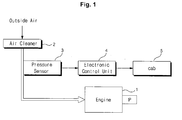
- a conventional apparatus for controlling engine revolutions for an excavator includes an engine 1 installed in the excavator; a pre-cleaner (not illustrated) for firstly separating outside air being inhaled into an engine combustion chamber into air and foreign substances, such as fine particles by applying a centrifugal force thereto; an air cleaner 2 for filtering out foreign substances, such as dust, soil, and the like, included in the outside air, which has passed through the pre-cleaner, through elements and supplying the filtered air to the engine combustion chamber (in the case of a wet type air cleaner, oil is replaced, while in the case of a dry type air cleaner, a filter is cleaned or replaced); a pressure sensor 3, installed in a bypass (i.e.
- an intake manifold between the air cleaner 2 and the engine combustion chamber, for detecting pressure of the air in the bypass and outputting a pressure signal corresponding to the detected pressure
- an electronic control unit (ECU) 4 for comparing the pressure signal inputted from the pressure sensor 3 with a predetermined reference pressure value, and if the pressure signal exceeds the reference pressure value, outputting a warning signal for requiring an operator in a cab 5 to check an engine intake system (including the air cleaner) having the increased pressure.
- the electronic control unit 4 transfers the warning signal to the operator to induce the operator to check the air cleaner 2.
- the foreign substances, such as dust, included in the outside air are directly inhaled into the engine combustion chamber, and this causes the damage of the engine 1 to shorten the lifespan of the engine.
- the present invention has been made to solve the above-mentioned problems occurring in the prior art while advantages achieved by the prior art are maintained intact.
- One object of the present invention is to provide an apparatus and method for controlling engine revolutions for an excavator, which can set working devices (e.g. a boom, an arm, and the like) of the excavator not to perform a normal operation by reducing a flow rate of hydraulic fluid discharged from a hydraulic pump through lowering of the engine revolutions if an operator disregards a warning signal for requiring the operator to check an engine intake system and continues the excavator work even when a predetermined time elapses after transfer of the warning signal to the operator.
- working devices e.g. a boom, an arm, and the like
- an apparatus for controlling engine revolutions for an excavator which includes an engine and a hydraulic pump installed in the excavator; an air cleaner for filtering out foreign substances included in outside air being inhaled into an engine combustion chamber through elements and supplying the filtered air to the engine combustion chamber; a pressure sensor, installed in a bypass between the air cleaner and the engine combustion chamber, for detecting pressure of the air in the bypass and outputting a pressure signal corresponding to the detected pressure; and an electronic control unit (ECU) for comparing the pressure signal inputted from the pressure sensor 3 with a predetermined reference pressure value, outputting a warning signal for requiring an operator in a cab to check the air cleaner if the pressure signal exceeds the reference pressure value, and lowering the engine revolutions and reducing a flow rate of hydraulic fluid discharged from the hydraulic pump if the operator disregards the warning signal and continues the excavator work after the transfer of the warning signal to the operator.
- ECU electronice control unit
- the warning signal may be transferred from the ECU to the operator in the cab through a warning light or a warning sound or message.
- a method for controlling engine revolutions for an excavator including an engine, a hydraulic pump, an air cleaner, a pressure sensor, and an electronic control unit, which includes a first step of detecting pressure of outside air being inhaled into an engine combustion chamber through the air cleaner using the pressure sensor; a second step of comparing a value of the pressure detected by the pressure sensor with a predetermined reference pressure value; a third step of transferring a warning signal for requiring an operator to check the air cleaner to the operator if the detected pressure value exceeds the reference pressure value; a fourth step of confirming whether the air cleaner has been checked; and a fifth step of lowering the engine revolution and reducing a flow rate of hydraulic fluid discharged from the hydraulic pump in accordance with a control signal from the electronic control unit if the operator disregards the warning signal and continues the excavator work after the transfer of the warning signal to the operator.
- the fifth step may include the steps of intervening in operation of working devices by firstly lowering the engine revolutions and reducing the flow rate of the hydraulic fluid discharged from the hydraulic pump if the operator disregards the warning signal and continues the excavator work after the transfer of the warning signal to the operator; and setting working devices of the excavator not to perform a normal operation by secondly lowering the engine revolutions and reducing the flow rate of the hydraulic fluid discharged from the hydraulic pump if the operator disregards the warning signal and continues the excavator work after the intervening in the operation of the working devices.
- the method for controlling engine revolutions may further include the step of judging that the operator has disregarded the warning signal if a predetermined time elapses after the transfer of the warning signal to the operator.
- the method for controlling engine revolutions may further include the step of judging that the operator has disregarded the warning signal if the warning signal is transferred to the operator over a predetermined number of times.
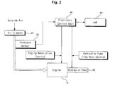
- an apparatus for controlling engine revolutions for an excavator includes an engine 10 installed in the excavator and a hydraulic pump 60 connected to the engine 10; an air cleaner 20 for filtering out foreign substances included in outside air being inhaled into an engine combustion chamber through elements and supplying the filtered air to the engine combustion chamber; a pressure sensor 30, installed in a bypass between the air cleaner 20 and the engine combustion chamber, for detecting pressure of the air in the bypass and outputting a pressure signal corresponding to the detected pressure; and an electronic control unit (ECU) 40 for comparing the pressure signal inputted from the pressure sensor 30 with a predetermined reference pressure value, outputting a warning signal for requiring an operator in a cab 50 to check the air cleaner 20 if the pressure signal exceeds the reference pressure value, and outputting a control signal for compulsorily lowering the revolutions of the engine 10 and reducing a flow rate of hydraulic fluid discharged from the hydraulic pump 60 if a predetermined time elapses after the transfer
- ECU electronice control unit
- the warning signal is transferred from the electronic control unit 40 to the operator in the cab 50 through a warning light or a warning sound or message.
- step S100 the pressure of the outside air being inhaled into the combustion chamber of the engine 10 after passing through the air cleaner 20 and an inhale tube under the operation of the engine is detected by the pressure sensor 30.
- the air cleaner 20 e.g. wet type air cleaner or dry type air cleaner.
- step S200 the pressure value corresponding to the pressure of the outside air detected by the pressure sensor 30 is compared with the predetermined reference pressure value.
- step S300 if the detected pressure value exceeds the reference pressure value (which corresponds to a state that the air cleaner 20 is severely polluted and thus the replacement of the air cleaner is required) as a result of comparison, it is judged that the replacement time of the air cleaner 20 arrives, and the warning signal is transferred to the operator so that the operator checks and confirms the intake system such as the air cleaner 20.
- the reference pressure value which corresponds to a state that the air cleaner 20 is severely polluted and thus the replacement of the air cleaner is required
- the warning signal may be transferred to the operator in the cab 50 through a warning light or a warning sound or message.
- step S400 after the transfer of the warning signal to the operator, it is judged whether the polluted air cleaner has been checked.
- step S500 if a predetermined time elapses after the transfer of the warning signal to the operator, or the warning signal is transferred to the operator over a predetermined number of times (which corresponds to a state that the operator disregards the warning signal and continues the excavator work), the revolutions of the engine 10 are lowered and the flow rate of the hydraulic fluid discharged from the hydraulic pump 60 is compulsorily reduced in accordance with the control signal from the electronic control unit 40.
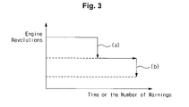
- the step S500 is to induce the operator to check the polluted air cleaner 20 and to perform the work. That is, if a predetermined time elapses after the transfer of the warning signal to the operator, or the warning signal is transferred to the operator over a predetermined number of times, the revolutions of the engine 10 is firstly lowered and the flow rate of the hydraulic fluid discharged from the hydraulic pump 60 is reduced (as indicated as section "a" in FIG. 3 ). Accordingly, the working device does not operate smoothly even if the operator manipulates the working device (such as a boom and so on).
- the operator disregards the warning signal for requiring the operator to check the air cleaner 20 and continues the excavator work in a state that the pressure value of the outside air of the intake system exceeds the reference pressure value due to the pollution of the air cleaner 20 and so on, the revolutions of the engine 10 are lowered, and the flow rate of the hydraulic fluid discharged from the hydraulic pump 60 is reduced. This induces the operator, who cannot perform the normal operation of the working device, to check the air cleaner 20.
Landscapes
- Engineering & Computer Science (AREA)
- Mining & Mineral Resources (AREA)
- Civil Engineering (AREA)
- General Engineering & Computer Science (AREA)
- Structural Engineering (AREA)
- Physics & Mathematics (AREA)
- Fluid Mechanics (AREA)
- Operation Control Of Excavators (AREA)
- Combined Controls Of Internal Combustion Engines (AREA)
- Control Of Vehicle Engines Or Engines For Specific Uses (AREA)
- Component Parts Of Construction Machinery (AREA)
- Electrical Control Of Air Or Fuel Supplied To Internal-Combustion Engine (AREA)
Abstract
Description
- This application is based on and claims priority from Korean Patent Application No.
10-2007-0115558, filed on November 13, 2007 - The present invention relates to an apparatus and method for controlling engine revolutions for an excavator, which can intervene in the operation of the excavator through lowering of the engine revolutions if an operator disregards a warning signal for requiring the operator to check an engine intake system and continues the excavator work even when a predetermined time elapses after transfer of the warning signal to the operator.
- More particularly, the present invention relates to an apparatus and method for controlling engine revolutions for an excavator, which can set the excavator not to perform a normal operation so as to induce an operator to check an air cleaner and so on by reducing a flow rate of hydraulic fluid discharged from a hydraulic pump through lowering of the engine revolutions if an operator disregards a warning signal for requiring the operator to check an engine intake system and continues the excavator work even when a predetermined time elapses after transfer of the warning signal to the operator or the warning signal is transferred to the operator over a predetermined number of times.
- In general, construction equipment such as an excavator works in inferior working environments. Outside air inhaled into an engine combustion chamber during the operation of the excavator includes foreign substances, such as fine particles including dust, soil, sand, and the like. Such outside air is supplied to the engine combustion chamber after being filtered through an air cleaner.
- That is, as the outside air is introduced into the engine combustion chamber after the foreign substances, such as soil, dust, and the like, included in the outside air are filtered out by the air cleaner, sliding parts of an engine are prevented from being worn down or damaged, and thus the lifespan of the corresponding parts are prolonged.
- The flow of the outside air into the engine combustion chamber may not be smooth due to the foreign substances accumulated in elements of the air cleaner to increase the resistance, and in this case, a corresponding system informs an operator in an operator's seat of the replacement time of the air cleaner and so on.
- As illustrated in
FIG. 1 , a conventional apparatus for controlling engine revolutions for an excavator includes an engine 1 installed in the excavator; a pre-cleaner (not illustrated) for firstly separating outside air being inhaled into an engine combustion chamber into air and foreign substances, such as fine particles by applying a centrifugal force thereto; an air cleaner 2 for filtering out foreign substances, such as dust, soil, and the like, included in the outside air, which has passed through the pre-cleaner, through elements and supplying the filtered air to the engine combustion chamber (in the case of a wet type air cleaner, oil is replaced, while in the case of a dry type air cleaner, a filter is cleaned or replaced); apressure sensor 3, installed in a bypass (i.e. an intake manifold) between the air cleaner 2 and the engine combustion chamber, for detecting pressure of the air in the bypass and outputting a pressure signal corresponding to the detected pressure; and an electronic control unit (ECU) 4 for comparing the pressure signal inputted from thepressure sensor 3 with a predetermined reference pressure value, and if the pressure signal exceeds the reference pressure value, outputting a warning signal for requiring an operator in acab 5 to check an engine intake system (including the air cleaner) having the increased pressure. - According to the conventional apparatus for controlling engine revolutions for an excavator as constructed above, if the pressure of the outside air being inhaled into the engine combustion chamber exceeds the predetermined reference pressure value due to the clogging of the air cleaner 2 and so on, the electronic control unit 4 transfers the warning signal to the operator to induce the operator to check the air cleaner 2.
- In this case, if the operator disregards the warning signal transferred from the electronic control unit 4 and continues the work, the consumption of fuel in the engine 1 is increased, and pipes and hoses constituting the intake system may be damaged.
- Accordingly, the foreign substances, such as dust, included in the outside air are directly inhaled into the engine combustion chamber, and this causes the damage of the engine 1 to shorten the lifespan of the engine.
- Accordingly, the present invention has been made to solve the above-mentioned problems occurring in the prior art while advantages achieved by the prior art are maintained intact.
- One object of the present invention is to provide an apparatus and method for controlling engine revolutions for an excavator, which can set working devices (e.g. a boom, an arm, and the like) of the excavator not to perform a normal operation by reducing a flow rate of hydraulic fluid discharged from a hydraulic pump through lowering of the engine revolutions if an operator disregards a warning signal for requiring the operator to check an engine intake system and continues the excavator work even when a predetermined time elapses after transfer of the warning signal to the operator.
- In order to accomplish this and other objects, there is provided an apparatus for controlling engine revolutions for an excavator, according to an embodiment of the present invention, which includes an engine and a hydraulic pump installed in the excavator; an air cleaner for filtering out foreign substances included in outside air being inhaled into an engine combustion chamber through elements and supplying the filtered air to the engine combustion chamber; a pressure sensor, installed in a bypass between the air cleaner and the engine combustion chamber, for detecting pressure of the air in the bypass and outputting a pressure signal corresponding to the detected pressure; and an electronic control unit (ECU) for comparing the pressure signal inputted from the
pressure sensor 3 with a predetermined reference pressure value, outputting a warning signal for requiring an operator in a cab to check the air cleaner if the pressure signal exceeds the reference pressure value, and lowering the engine revolutions and reducing a flow rate of hydraulic fluid discharged from the hydraulic pump if the operator disregards the warning signal and continues the excavator work after the transfer of the warning signal to the operator. - In a preferred embodiment of the present invention, the warning signal may be transferred from the ECU to the operator in the cab through a warning light or a warning sound or message.
- In another aspect of the present invention, there is provided a method for controlling engine revolutions for an excavator including an engine, a hydraulic pump, an air cleaner, a pressure sensor, and an electronic control unit, which includes a first step of detecting pressure of outside air being inhaled into an engine combustion chamber through the air cleaner using the pressure sensor; a second step of comparing a value of the pressure detected by the pressure sensor with a predetermined reference pressure value; a third step of transferring a warning signal for requiring an operator to check the air cleaner to the operator if the detected pressure value exceeds the reference pressure value; a fourth step of confirming whether the air cleaner has been checked; and a fifth step of lowering the engine revolution and reducing a flow rate of hydraulic fluid discharged from the hydraulic pump in accordance with a control signal from the electronic control unit if the operator disregards the warning signal and continues the excavator work after the transfer of the warning signal to the operator.
- The fifth step may include the steps of intervening in operation of working devices by firstly lowering the engine revolutions and reducing the flow rate of the hydraulic fluid discharged from the hydraulic pump if the operator disregards the warning signal and continues the excavator work after the transfer of the warning signal to the operator; and setting working devices of the excavator not to perform a normal operation by secondly lowering the engine revolutions and reducing the flow rate of the hydraulic fluid discharged from the hydraulic pump if the operator disregards the warning signal and continues the excavator work after the intervening in the operation of the working devices.
- The method for controlling engine revolutions according to an embodiment of the present invention may further include the step of judging that the operator has disregarded the warning signal if a predetermined time elapses after the transfer of the warning signal to the operator.
- The method for controlling engine revolutions according to an embodiment of the present invention may further include the step of judging that the operator has disregarded the warning signal if the warning signal is transferred to the operator over a predetermined number of times.
- With the above-described construction, if an operator disregards a warning signal for requiring the operator to check an engine intake system and continues the excavator work even when a predetermined time elapses after transfer of the warning signal to the operator or the warning signal is transferred to the operator over a predetermined number of times, the flow rate of hydraulic fluid discharged from a hydraulic pump is reduced through lowering of the engine revolutions, and thus the excavator does not perform a normal operation, so that an operator checks the engine intake system to protect the engine.
- The above and other objects, features and advantages of the present invention will be more apparent from the following detailed description taken in conjunction with the accompanying drawings, in which:
-
FIG. 1 is a schematic block diagram illustrating the configuration of a conventional apparatus for controlling engine revolutions for an excavator; -
FIG. 2 is a schematic block diagram illustrating the configuration of an apparatus for controlling engine revolutions for an excavator according to an embodiment of the present invention; -
FIG. 3 is a graph explaining the control of engine revolution performed by the apparatus for controlling engine revolutions for an excavator according to an embodiment of the present invention; and -
FIG. 4 is a flowchart illustrating a method for controlling engine revolutions for an excavator according to an embodiment of the present invention. - Hereinafter, preferred embodiments of the present invention will be described with reference to the accompanying drawings. The matters defined in the description, such as the detailed construction and elements, are nothing but specific details provided to assist those of ordinary skill in the art in a comprehensive understanding of the invention, and thus the present invention is not limited thereto.
- As illustrated in
FIG. 2 , an apparatus for controlling engine revolutions for an excavator according to an embodiment of the present invention includes anengine 10 installed in the excavator and ahydraulic pump 60 connected to theengine 10; anair cleaner 20 for filtering out foreign substances included in outside air being inhaled into an engine combustion chamber through elements and supplying the filtered air to the engine combustion chamber; a pressure sensor 30, installed in a bypass between theair cleaner 20 and the engine combustion chamber, for detecting pressure of the air in the bypass and outputting a pressure signal corresponding to the detected pressure; and an electronic control unit (ECU) 40 for comparing the pressure signal inputted from the pressure sensor 30 with a predetermined reference pressure value, outputting a warning signal for requiring an operator in acab 50 to check theair cleaner 20 if the pressure signal exceeds the reference pressure value, and outputting a control signal for compulsorily lowering the revolutions of theengine 10 and reducing a flow rate of hydraulic fluid discharged from thehydraulic pump 60 if a predetermined time elapses after the transfer of the warning signal to the operator or the warning signal is transferred to the operator over a predetermined number of times. - The warning signal is transferred from the
electronic control unit 40 to the operator in thecab 50 through a warning light or a warning sound or message. - Since the techniques of inhaling the outside air to the combustion chamber of the
engine 10 through theair cleaner 20 during the operation of theengine 10, inputting the pressure signal of the outside air detected by the pressure sensor 30 to theelectronic control unit 40, and lowering the revolutions of theengine 10 and reducing the flow rate of the hydraulic fluid discharged from thehydraulic pump 60 in accordance with the control signal from theelectronic control unit 40 are known in the technical field to which the present invention pertains, the detailed description thereof will be omitted. - Hereinafter, the apparatus and method for controlling engine revolutions for an excavator according to an embodiment of the present invention will be described with reference to the accompanying drawings.
- Referring to
FIGS. 2 to 4 , in step S100, the pressure of the outside air being inhaled into the combustion chamber of theengine 10 after passing through theair cleaner 20 and an inhale tube under the operation of the engine is detected by the pressure sensor 30. - In this case, foreign substances, such as dust, fine particles, soil, and the like, included in the outside air being inhaled into the combustion chamber of the
engine 10 are filtered out by the air cleaner 20 (e.g. wet type air cleaner or dry type air cleaner). - In step S200, the pressure value corresponding to the pressure of the outside air detected by the pressure sensor 30 is compared with the predetermined reference pressure value.
- In step S300, if the detected pressure value exceeds the reference pressure value (which corresponds to a state that the
air cleaner 20 is severely polluted and thus the replacement of the air cleaner is required) as a result of comparison, it is judged that the replacement time of theair cleaner 20 arrives, and the warning signal is transferred to the operator so that the operator checks and confirms the intake system such as theair cleaner 20. - In this case, the warning signal may be transferred to the operator in the
cab 50 through a warning light or a warning sound or message. - In step S400, after the transfer of the warning signal to the operator, it is judged whether the polluted air cleaner has been checked.
- In step S500, if a predetermined time elapses after the transfer of the warning signal to the operator, or the warning signal is transferred to the operator over a predetermined number of times (which corresponds to a state that the operator disregards the warning signal and continues the excavator work), the revolutions of the
engine 10 are lowered and the flow rate of the hydraulic fluid discharged from thehydraulic pump 60 is compulsorily reduced in accordance with the control signal from theelectronic control unit 40. - The step S500 is to induce the operator to check the polluted
air cleaner 20 and to perform the work. That is, if a predetermined time elapses after the transfer of the warning signal to the operator, or the warning signal is transferred to the operator over a predetermined number of times, the revolutions of theengine 10 is firstly lowered and the flow rate of the hydraulic fluid discharged from thehydraulic pump 60 is reduced (as indicated as section "a" inFIG. 3 ). Accordingly, the working device does not operate smoothly even if the operator manipulates the working device (such as a boom and so on). - On the other hand, if the operator continues the working after the transfer of the warning through the intervening in the operation of the working device, the revolutions of the
engine 10 are secondly lowered and the flow rate of the hydraulic fluid discharged from thehydraulic pump 60 is reduced (as indicated as section "b" inFIG. 3 ). Accordingly, the operating speed of the working device is considerably lowered even if the operator forcibly manipulates the working device. - As described above, if the operator disregards the warning signal for requiring the operator to check the
air cleaner 20 and continues the excavator work in a state that the pressure value of the outside air of the intake system exceeds the reference pressure value due to the pollution of theair cleaner 20 and so on, the revolutions of theengine 10 are lowered, and the flow rate of the hydraulic fluid discharged from thehydraulic pump 60 is reduced. This induces the operator, who cannot perform the normal operation of the working device, to check theair cleaner 20. - Although preferred embodiment of the present invention has been described for illustrative purposes, those skilled in the art will appreciate that various modifications, additions and substitutions are possible, without departing from the scope and spirit of the invention as disclosed in the accompanying claims.
Claims (6)
- An apparatus for controlling engine revolutions for an excavator, comprising:an engine and a hydraulic pump installed in the excavator;an air cleaner for filtering out foreign substances included in outside air being inhaled into an engine combustion chamber through elements and supplying the filtered air to the engine combustion chamber;a pressure sensor, installed in a bypass between the air cleaner and the engine combustion chamber, for detecting pressure of the air in the bypass and outputting a pressure signal corresponding to the detected pressure; andan electronic control unit (ECU) for comparing the pressure signal inputted from the pressure sensor 3 with a predetermined reference pressure value, outputting a warning signal for requiring an operator in a cab to check the air cleaner if the pressure signal exceeds the reference pressure value, and lowering the engine revolutions and reducing a flow rate of hydraulic fluid discharged from the hydraulic pump if the operator disregards the warning signal and continues the excavator work after the transfer of the warning signal to the operator.
- The apparatus of claim 1, wherein the warning signal is transferred from the ECU to the operator in the cab through a warning light or a warning sound or message.
- A method for controlling engine revolutions for an excavator including an engine, a hydraulic pump, an air cleaner, a pressure sensor, and an electronic control unit, the method comprising:a first step of detecting pressure of outside air being inhaled into an engine combustion chamber through the air cleaner using the pressure sensor;a second step of comparing a value of the pressure detected by the pressure sensor with a predetermined reference pressure value;a third step of transferring a warning signal for requiring an operator to check the air cleaner to the operator if the detected pressure value exceeds the reference pressure value;a fourth step of confirming whether the air cleaner has been checked; anda fifth step of lowering the engine revolutions and reducing a flow rate of hydraulic fluid discharged from the hydraulic pump in accordance with a control signal from the electronic control unit if the operator disregards the warning signal and continues the excavator work after the transfer of the warning signal to the operator.
- The method of claim 3, wherein the fifth step comprises the steps of:intervening in operation of working devices by firstly lowering the engine revolutions and reducing the flow rate of the hydraulic fluid discharged from the hydraulic pump if the operator disregards the warning signal and continues the excavator work after the transfer of the warning signal to the operator; andsetting working devices of the excavator not to perform a normal operation by secondly lowering the engine revolutions and reducing the flow rate of the hydraulic fluid discharged from the hydraulic pump if the operator disregards the warning signal and continues the excavator work after the intervening in the operation of the working devices.
- The method of claim 3 or 4, further comprising the step of judging that the operator has disregarded the warning signal if a predetermined time elapses after the transfer of the warning signal to the operator.
- The method of claim 3 or 4, further comprising the step of judging that the operator has disregarded the warning signal if the warning signal is transferred to the operator over a predetermined number of times.
Applications Claiming Priority (1)
| Application Number | Priority Date | Filing Date | Title |
|---|---|---|---|
| KR1020070115558A KR20090049334A (en) | 2007-11-13 | 2007-11-13 | Engine speed control device for excavator and its control method |
Publications (2)
| Publication Number | Publication Date |
|---|---|
| EP2060681A2 true EP2060681A2 (en) | 2009-05-20 |
| EP2060681A3 EP2060681A3 (en) | 2017-03-15 |
Family
ID=40344572
Family Applications (1)
| Application Number | Title | Priority Date | Filing Date |
|---|---|---|---|
| EP08019562.1A Withdrawn EP2060681A3 (en) | 2007-11-13 | 2008-11-08 | Apparatus and method for controlling engine revolutions for excavator |
Country Status (5)
| Country | Link |
|---|---|
| US (1) | US20090125198A1 (en) |
| EP (1) | EP2060681A3 (en) |
| JP (1) | JP2009121464A (en) |
| KR (1) | KR20090049334A (en) |
| CN (1) | CN101435210B (en) |
Cited By (1)
| Publication number | Priority date | Publication date | Assignee | Title |
|---|---|---|---|---|
| EP3015689A4 (en) * | 2013-06-26 | 2017-03-08 | Volvo Construction Equipment AB | Device and method for controlling engine rpm for construction machinery |
Families Citing this family (9)
| Publication number | Priority date | Publication date | Assignee | Title |
|---|---|---|---|---|
| JP2013534294A (en) * | 2010-08-17 | 2013-09-02 | ボルボ コンストラクション イクイップメント アーベー | Engine protection device to prevent moisture inflow |
| CN102505726B (en) * | 2011-11-08 | 2014-04-02 | 三一重机有限公司 | Control method of automatic calibration in rotation speed of excavator |
| ES2686355T3 (en) * | 2014-06-27 | 2018-10-17 | Fpt Motorenforschung Ag | System for detecting an air filter condition, in particular for combustion engines |
| JP2018035570A (en) * | 2016-08-31 | 2018-03-08 | 住友建機株式会社 | Excavator |
| WO2021102333A1 (en) * | 2019-11-20 | 2021-05-27 | Autonomous Solutions, Inc. | Autonomous loader controller |
| CN111335395B (en) * | 2020-02-26 | 2021-11-05 | 上海三一重机股份有限公司 | Excavator rotating speed protection control method and device, excavator and storage medium |
| GB2606227B (en) * | 2021-04-30 | 2023-11-15 | Dyson Technology Ltd | Haircare appliance |
| CN115586007B (en) * | 2022-10-08 | 2025-09-16 | 东风柳州汽车有限公司 | Rack timing alarm protection system and method |
| CN120608777B (en) * | 2025-08-11 | 2025-10-10 | 中国水利水电第六工程局有限公司 | Underground plant excavation equipment and control method thereof |
Family Cites Families (14)
| Publication number | Priority date | Publication date | Assignee | Title |
|---|---|---|---|---|
| US4029073A (en) * | 1975-07-14 | 1977-06-14 | James Dey | Automatic motor kill system for preventing damage to a heavy equipment motor due to a dirty air filter |
| US5205261A (en) * | 1992-07-07 | 1993-04-27 | Caterpillar Inc. | Air restriction derate for internal combustion engines |
| JPH07279714A (en) * | 1994-04-13 | 1995-10-27 | Yamaha Motor Co Ltd | Gas fuel engine |
| JPH0893518A (en) * | 1994-09-20 | 1996-04-09 | Yazaki Corp | Vehicle control device when stopped |
| JPH08268091A (en) * | 1995-03-31 | 1996-10-15 | Hitachi Constr Mach Co Ltd | Engine intake structure of construction machinery |
| JP3703575B2 (en) * | 1996-08-30 | 2005-10-05 | 日立建機株式会社 | Operational machine remaining time prediction device |
| RU2158805C1 (en) * | 1999-03-09 | 2000-11-10 | Курский государственный технический университет | Lifting-and-digging mechanism control device |
| US7021074B2 (en) * | 2003-03-10 | 2006-04-04 | Kubota Corporation | Work vehicle |
| US7349794B2 (en) * | 2003-09-03 | 2008-03-25 | Malone Specialty, Inc. | Engine protection system |
| JP4188902B2 (en) * | 2004-11-22 | 2008-12-03 | 日立建機株式会社 | Control equipment for hydraulic construction machinery |
| CN2816384Y (en) * | 2005-03-07 | 2006-09-13 | 深圳市乾程电子有限公司 | Electric-controlled energy-saving purifying device generally for motor vehicles |
| JP4580803B2 (en) * | 2005-03-31 | 2010-11-17 | キャタピラー エス エー アール エル | Clogging notification device for exhaust gas purification device for internal combustion engine |
| US20070142169A1 (en) * | 2005-12-16 | 2007-06-21 | Jean-Pierre Marcil | Erroneous sudden acceleration neutralization system and method |
| JP4610514B2 (en) * | 2006-04-20 | 2011-01-12 | ヤンマー株式会社 | engine |
-
2007
- 2007-11-13 KR KR1020070115558A patent/KR20090049334A/en not_active Ceased
-
2008
- 2008-11-03 US US12/263,547 patent/US20090125198A1/en not_active Abandoned
- 2008-11-06 JP JP2008285248A patent/JP2009121464A/en active Pending
- 2008-11-08 EP EP08019562.1A patent/EP2060681A3/en not_active Withdrawn
- 2008-11-12 CN CN2008101673785A patent/CN101435210B/en not_active Expired - Fee Related
Cited By (1)
| Publication number | Priority date | Publication date | Assignee | Title |
|---|---|---|---|---|
| EP3015689A4 (en) * | 2013-06-26 | 2017-03-08 | Volvo Construction Equipment AB | Device and method for controlling engine rpm for construction machinery |
Also Published As
| Publication number | Publication date |
|---|---|
| CN101435210B (en) | 2012-11-07 |
| EP2060681A3 (en) | 2017-03-15 |
| CN101435210A (en) | 2009-05-20 |
| JP2009121464A (en) | 2009-06-04 |
| KR20090049334A (en) | 2009-05-18 |
| US20090125198A1 (en) | 2009-05-14 |
Similar Documents
| Publication | Publication Date | Title |
|---|---|---|
| US20090125198A1 (en) | Apparatus and method for controlling engine revolutions for excavator | |
| CN102046932B (en) | Exhaust gas purification device | |
| JP5220856B2 (en) | Construction machinery | |
| CN104066940B (en) | construction machinery | |
| JP5845285B2 (en) | Construction machinery | |
| KR101678079B1 (en) | Hydraulic working machine | |
| CN101554924A (en) | Device for feeding combustion air to an air craft engines | |
| KR101734977B1 (en) | Construction machine | |
| KR102116915B1 (en) | Construction machinery | |
| CN202338421U (en) | Air filter device for mine wide-body dump truck | |
| JPH09250510A (en) | Protection equipment for hydraulic circuits in work machines | |
| CN105339633A (en) | Device and method for controlling engine RPM for construction machinery | |
| JP2023163916A (en) | Abnormality detection device for hydraulic fluid tank, abnormality detection method for hydraulic fluid tank, and abnormality detection program for hydraulic fluid tank | |
| KR20100030442A (en) | Air cleaner assembly for heavy construction equipment | |
| CN116265057A (en) | Automatic dredging and filtering system for crude oil gathering and transportation pipeline and its application method | |
| JPH09250407A (en) | Air cleaner device | |
| JP2007056864A (en) | Exhaust gas treatment apparatus and exhaust gas treatment method | |
| JP2010270610A (en) | Dpf self-regeneration device for construction machine |
Legal Events
| Date | Code | Title | Description |
|---|---|---|---|
| PUAI | Public reference made under article 153(3) epc to a published international application that has entered the european phase |
Free format text: ORIGINAL CODE: 0009012 |
|
| AK | Designated contracting states |
Kind code of ref document: A2 Designated state(s): AT BE BG CH CY CZ DE DK EE ES FI FR GB GR HR HU IE IS IT LI LT LU LV MC MT NL NO PL PT RO SE SI SK TR |
|
| AX | Request for extension of the european patent |
Extension state: AL BA MK RS |
|
| PUAL | Search report despatched |
Free format text: ORIGINAL CODE: 0009013 |
|
| AK | Designated contracting states |
Kind code of ref document: A3 Designated state(s): AT BE BG CH CY CZ DE DK EE ES FI FR GB GR HR HU IE IS IT LI LT LU LV MC MT NL NO PL PT RO SE SI SK TR |
|
| AX | Request for extension of the european patent |
Extension state: AL BA MK RS |
|
| RIC1 | Information provided on ipc code assigned before grant |
Ipc: B60W 50/02 20120101ALI20170209BHEP Ipc: E02F 9/20 20060101AFI20170209BHEP Ipc: E02F 9/22 20060101ALI20170209BHEP Ipc: E02F 9/26 20060101ALI20170209BHEP |
|
| REG | Reference to a national code |
Ref country code: DE Ref legal event code: R108 |
|
| AKY | No designation fees paid | ||
| AXX | Extension fees paid |
Extension state: RS Extension state: BA Extension state: AL Extension state: MK |
|
| STAA | Information on the status of an ep patent application or granted ep patent |
Free format text: STATUS: THE APPLICATION IS DEEMED TO BE WITHDRAWN |
|
| 18D | Application deemed to be withdrawn |
Effective date: 20170916 |