EP2060669A1 - Bearing housing and washing machine therewith - Google Patents
Bearing housing and washing machine therewith Download PDFInfo
- Publication number
- EP2060669A1 EP2060669A1 EP08168326A EP08168326A EP2060669A1 EP 2060669 A1 EP2060669 A1 EP 2060669A1 EP 08168326 A EP08168326 A EP 08168326A EP 08168326 A EP08168326 A EP 08168326A EP 2060669 A1 EP2060669 A1 EP 2060669A1
- Authority
- EP
- European Patent Office
- Prior art keywords
- bearing housing
- tub
- rib
- washing machine
- bearing
- Prior art date
- Legal status (The legal status is an assumption and is not a legal conclusion. Google has not performed a legal analysis and makes no representation as to the accuracy of the status listed.)
- Withdrawn
Links
Images


Classifications
-
- D—TEXTILES; PAPER
- D06—TREATMENT OF TEXTILES OR THE LIKE; LAUNDERING; FLEXIBLE MATERIALS NOT OTHERWISE PROVIDED FOR
- D06F—LAUNDERING, DRYING, IRONING, PRESSING OR FOLDING TEXTILE ARTICLES
- D06F37/00—Details specific to washing machines covered by groups D06F21/00 - D06F25/00
- D06F37/26—Casings; Tubs
- D06F37/267—Tubs specially adapted for mounting thereto components or devices not provided for in preceding subgroups
- D06F37/269—Tubs specially adapted for mounting thereto components or devices not provided for in preceding subgroups for the bearing of the rotary receptacle
-
- D—TEXTILES; PAPER
- D06—TREATMENT OF TEXTILES OR THE LIKE; LAUNDERING; FLEXIBLE MATERIALS NOT OTHERWISE PROVIDED FOR
- D06F—LAUNDERING, DRYING, IRONING, PRESSING OR FOLDING TEXTILE ARTICLES
- D06F37/00—Details specific to washing machines covered by groups D06F21/00 - D06F25/00
- D06F37/02—Rotary receptacles, e.g. drums
-
- D—TEXTILES; PAPER
- D06—TREATMENT OF TEXTILES OR THE LIKE; LAUNDERING; FLEXIBLE MATERIALS NOT OTHERWISE PROVIDED FOR
- D06F—LAUNDERING, DRYING, IRONING, PRESSING OR FOLDING TEXTILE ARTICLES
- D06F37/00—Details specific to washing machines covered by groups D06F21/00 - D06F25/00
- D06F37/20—Mountings, e.g. resilient mountings, for the rotary receptacle, motor, tub or casing; Preventing or damping vibrations
- D06F37/206—Mounting of motor
-
- D—TEXTILES; PAPER
- D06—TREATMENT OF TEXTILES OR THE LIKE; LAUNDERING; FLEXIBLE MATERIALS NOT OTHERWISE PROVIDED FOR
- D06F—LAUNDERING, DRYING, IRONING, PRESSING OR FOLDING TEXTILE ARTICLES
- D06F37/00—Details specific to washing machines covered by groups D06F21/00 - D06F25/00
- D06F37/26—Casings; Tubs
- D06F37/261—Tubs made by a specially selected manufacturing process or characterised by their assembly from elements
- D06F37/262—Tubs made by a specially selected manufacturing process or characterised by their assembly from elements made of plastic material, e.g. by injection moulding
-
- D—TEXTILES; PAPER
- D06—TREATMENT OF TEXTILES OR THE LIKE; LAUNDERING; FLEXIBLE MATERIALS NOT OTHERWISE PROVIDED FOR
- D06F—LAUNDERING, DRYING, IRONING, PRESSING OR FOLDING TEXTILE ARTICLES
- D06F37/00—Details specific to washing machines covered by groups D06F21/00 - D06F25/00
- D06F37/26—Casings; Tubs
- D06F37/264—Tubs provided with reinforcing structures, e.g. ribs, inserts, braces
-
- D—TEXTILES; PAPER
- D06—TREATMENT OF TEXTILES OR THE LIKE; LAUNDERING; FLEXIBLE MATERIALS NOT OTHERWISE PROVIDED FOR
- D06F—LAUNDERING, DRYING, IRONING, PRESSING OR FOLDING TEXTILE ARTICLES
- D06F37/00—Details specific to washing machines covered by groups D06F21/00 - D06F25/00
- D06F37/26—Casings; Tubs
- D06F37/267—Tubs specially adapted for mounting thereto components or devices not provided for in preceding subgroups
- D06F37/268—Tubs specially adapted for mounting thereto components or devices not provided for in preceding subgroups for suspension devices
-
- D—TEXTILES; PAPER
- D06—TREATMENT OF TEXTILES OR THE LIKE; LAUNDERING; FLEXIBLE MATERIALS NOT OTHERWISE PROVIDED FOR
- D06F—LAUNDERING, DRYING, IRONING, PRESSING OR FOLDING TEXTILE ARTICLES
- D06F39/00—Details of washing machines not specific to a single type of machines covered by groups D06F9/00 - D06F27/00
- D06F39/12—Casings; Tubs
-
- Y—GENERAL TAGGING OF NEW TECHNOLOGICAL DEVELOPMENTS; GENERAL TAGGING OF CROSS-SECTIONAL TECHNOLOGIES SPANNING OVER SEVERAL SECTIONS OF THE IPC; TECHNICAL SUBJECTS COVERED BY FORMER USPC CROSS-REFERENCE ART COLLECTIONS [XRACs] AND DIGESTS
- Y02—TECHNOLOGIES OR APPLICATIONS FOR MITIGATION OR ADAPTATION AGAINST CLIMATE CHANGE
- Y02B—CLIMATE CHANGE MITIGATION TECHNOLOGIES RELATED TO BUILDINGS, e.g. HOUSING, HOUSE APPLIANCES OR RELATED END-USER APPLICATIONS
- Y02B40/00—Technologies aiming at improving the efficiency of home appliances, e.g. induction cooking or efficient technologies for refrigerators, freezers or dish washers
Definitions
- the present invention relates to a bearing housing and, more particularly, to a bearing housing capable of simplifying an assembly process and maintaining concentricity of a stator, and a washing machine including the same.
- a washing machine is designed to wash laundry using a suitable detergent and mechanical force.
- a drum type washing machine is designed to receive the laundry in a horizontally disposed drum which is rotated by a drive force from a motor, and to wash the laundry by impact generated between the laundry and the drum when the laundry is lifted and dropped inside the rotating drum.
- the drum type washing machine has many advantages, such as minimal damage to and less entanglement of laundry, etc.
- Fig. 1 is a sectional view illustrating a rear side of a tube of a conventional washing machine
- Fig. 2 is a perspective view of a bearing housing shown in Fig. 1 .
- a conventional washing machine includes a cabinet (not shown) having a tub 2 and a drum 4 in which laundry is washed, and a door (not shown) attached to the cabinet to open or close an opening of the cabinet through which laundry is input into and removed from the drum 4.
- the drum 4 is rotatably disposed inside the tub 2, on the rear side of which a motor 10 is mounted to rotate the drum 4.
- the motor 10 is connected with the drum 4 via a rotational shaft 12 to transmit a rotational force to the drum 4.
- the motor 10 includes a rotor 14 connected with the shaft 12 to cooperate therewith and a stator 16 disposed inside the rotor 14 to face the rear side of the tub 12.
- a spider 18 is fastened between the drum 4 and the rotational shaft 12 to ensure more effective transmission of the rotational force from the motor 10 to the drum 4 through the rotational shaft 12.
- the tub 2 is formed at the center of the rear side with a through-hole 2a through which the rotational shaft 12 passes, and which has a bearing housing 22 disposed therein and having a bearing 20 supporting the rotational shaft 12.
- the bearing housing 22 is formed integrally with the tub 2 via insert-injection molding. As shown in Fig. 2 , the bearing housing 22 includes a bearing support 22a for supporting the bearing and a stator fastening part 22b formed outside the bearing support 22a. The stator fastening part 22b is formed with a rib 22c.
- a metallic supporter 24 is secured to the rear wall of the tub 2 to be disposed between the rear wall of the tub 2 and the stator 16.
- One side of the supporter 24 closely contacts the rear wall of the tub 2, and the other side thereof closely contacts an outer circumference of the bearing housing 22 to maintain concentricity of the stator 16 while supporting the stator 16.
- the tube is made of a different material from that of the bearing housing, a space between the tub and the bearing housing, specifically, the space in the stator fastening part is not filled with a resin, thereby forming a void therein due to different shrinkage rates by cooling during injection molding of the tub. As a result, coupling strength between the tub and the bearing housing is weakened. Therefore, there is a need for solving these problems of the conventional washing machine.
- the present invention is conceived to solve the problems of the conventional techniques as described above, and an aspect of the present invention is to provide a washing machine that can ensure a supporting force and concentricity with respect to a bearing housing and a stator at a rear wall of a tub while simplifying an assembly process, and that is improved in structure to increase coupling strength between the tub and the bearing housing.
- a bearing housing includes: a bearing support supporting a bearing; a rib formed integrally with the bearing support and including a penetration part; and a flange part extending radially from the rib.
- the rib may further include a partition dividing the penetration part.
- the rib may further include a closed part.
- the rib may further include a partition disposed between the penetration part and the closed part to divide the penetration part and the closed part.
- the flange part may include a bottom surface portion constituting a bottom of the flange part and an upper surface portion extending from the bottom portion to form a step between the bottom surface portion and the upper surface portion.
- the upper surface portion may be formed with a protrusion extending radially from an outer circumference thereof.
- the flange part may be formed with a flange rib bent from an outer circumference thereof.
- a washing machine includes: a tub; a bearing housing formed by insert injection molding into the tub; and a stator coupled to the bearing housing, the bearing housing including a bearing support to support a bearing, a rib formed integrally with the bearing support and including a penetration part, and a flange part extending radially from the rib.
- the bearing housing may be formed with a fastening part to which the stator is coupled, and may be insert-injection molded into the tub to expose the fastening part from the tub.
- the rib may further include a partition dividing the penetration part.
- the rib may further include a closed part, and the closed part may be open at one side thereof facing the stator and may be closed at the other side.
- the rib may further include a partition disposed between the penetration part and the closed part to divide the penetration part and the closed part.
- the flange part may include a bottom surface portion constituting a bottom of the flange part and an upper surface portion extending from the bottom surface portion to form a step between the bottom surface portion and the upper surface portion.
- the flange part may have a flange rib bent from an outer circumference thereof.
- Fig. 3 is a section side elevation of a washing machine according to an embodiment of the present invention
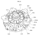
- Fig. 4 is a perspective view of a bearing housing shown in Fig. 3
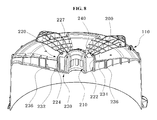
- Fig. 5 is a plan view of the bearing housing shown in Fig. 3 .
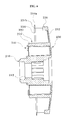
- Fig. 6 is a cross-sectional view taken along line VI-VI
- Fig. 7 is a cross-sectional view taken along line VII-VII
- Fig. 8 is a partially sectional perspective view of the washing machine of Fig. 3 with some components omitted therefrom
- Fig. 9 is a plan view of a bearing housing according to another embodiment of the present invention.
- the washing machine 400 includes a tub 100, a bearing housing 200, and a stator 300.
- the tub 100 is an injection molded product and can be formed of plastics or synthetic resins (hereinafter, generally referred to as a "resin").
- the tub 100 is disposed inside a cabinet (not shown), and has a drum 30 rotatably disposed inside the tub 100.
- a shaft 50 is connected with the drum 30 through the center of a rear wall of the tub 100 to transmit a drive force from a motor 40 to the drum 30.
- the washing machine 400 since the tub 100 is made of a lightweight resin through injection molding, the washing machine 400 has a light weight and improved productivity.
- the tub 100 is provided at the center of a rear wall thereof with a bearing housing 200 for supporting a bearing 60 disposed at either end of the shaft 50 while being fastened to the stator 300.
- the bearing housing 200 is insert-injection molded into the rear wall of the tub 100 to be integral with the rear wall of the tub 100 during injection molding of the tub 100. As shown in Figs. 4 to 7 , the bearing housing 200 includes a bearing support 210, a rib 220, and a flange part 230.
- the bearing support 210 is formed in a sleeve shape to be inserted into the center of the rear wall of the tub 100, and has a stepped surface 212 formed on an inner surface thereof to support the bearing 60.
- the rib 220 is integral with the bearing support 210 and extends radially from the bearing support 210.
- the rib 220 serves to increase a coupling force between the resin and the bearing housing 200 when the bearing housing 200 is insert-injection molded into the tub 100.
- the rib 220 has a penetration part 222.
- the penetration part 222 is formed with a through-hole 222a.
- the through-hole 222a is filled with a resin when the bearing housing 200 is insert-injection molded into the tub 100. Since the through-hole 222a is filled with the resin, the penetration part 222 is surrounded by the resin, as shown in Fig. 8 .
- the bearing housing 200 is insert-injection molded into the tub 100 such that both inner and outer sides of the bearing housing 200 are surrounded by the tub 100. As a result, the bearing housing 200 is further rigidly coupled to the tub 100.
- the rib 220 may further include a closed part 224.
- the closed part 224 is formed outside the bearing support 210 to be located between the penetration parts 222.
- the bearing housing 200 further includes a partition 226 between the penetration part 222 and the closed part 224 to divide the penetration part 222 and the closed part 224.
- the partition 226 has a rib shape.
- the closed part 224 is open at one side thereof facing a stator, and is closed at the other side thereof, which is inserted into the tub 100.
- the closed part 224 is also filled with the resin during insert injection molding of the bearing housing 200, but is different from the penetration part 222 in that a coupling structure of the closed part 224 with respect to the tub 100 is different from that of the penetration part 222 since the other side of the closed part 224 inserted into the tub 100 is closed.
- the closed part 224 is not completely filled with the resin to such a degree that the resin penetrates the closed part 224.
- the closed part 224 is configured to allow the resin to be introduced into the closed part 224 and to have the closed other side disposed in parallel with the rear wall of the tub 100, thereby increasing the coupling force between the bearing housing 200 and the resin. Additionally, the closed part 224 serves to allow the bearing housing 200 to be further rigidly coupled to the rear wall of the tub 100 by imparting surface resistance to an interface between the tub 100 and the bearing housing 200.
- the flange part 230 is connected with the rib 220 and extends radially from the rib 220 to be inserted into the tub 100.
- the flange part 230 includes a bottom surface portion 232 constituting the bottom of the flange part 230 and an upper surface portion 234 extending from the bottom surface portion 232 to form a step between the bottom surface portion 232 and the upper surface portion 234. In this manner, the flange part 230 is generally formed to have a concave-convex shape.
- the flange part 230 enlarges a coupling area between the tub 100 and the bearing housing 200, thereby increasing rigidity of the coupling area between the rear wall of the tub 100 and the bearing housing 200 during the insert injection molding of the bearing housing 200. Further, the flange part 230 serves to effectively absorb and damp vibration of the motor 40 during operation of the washing machine.
- the upper surface portion 234 of the flange part 230 may include a protrusion 234a formed thereon.
- the protrusion 234a protrudes from an outer circumference of the upper surface portion 234 and serves to further enlarge the coupling area between the tub 100 and the bearing housing 200.
- the protrusion 234a may be formed with a through-hole 234b, thereby increasing the coupling force between the resin and the bearing housing 200 during the insert injection molding of the bearing housing 200.
- the flange part 230 may further include a flange rib 236.
- the flange rib 236 is bent from the outer circumference of the flange part 230.
- the flange rib 236 reinforces the flange part 230 and the bearing housing 200 comprising the flange part, and serves to further increase the coupling force between the resin and the bearing housing 200 during the insert injection molding of the bearing housing 200.
- the stator 300 constituting the motor 40 together with the rotor 45 is coupled to the bearing housing 200 so that the stator 300 is secured to the tub 100.
- the bearing housing 200 further includes a fastening part 240, as shown in Figs. 4 to 8 .
- the fastening part 240 is formed so as not to be embedded in the tub 100, but to be exposed from the resin, as is different from other components of the bearing housing 200 which are embedded in the tub 100 by insert injection during injection molding of the tub 100.
- the fastening part 240 is formed with a fastening hole 242, which has a thread formed therein.
- the fastening part 240 may be formed to protrude from the bearing housing 200 towards the stator 300 and to have a thread formed on a protruded outer circumferential surface of the fastening part 240.
- the bearing housing 200 is provided with the fastening part 240 that has the fastening hole 242 therein, thereby eliminating a separate process of forming the fastening hole in the tub 100.
- the rib 220 including the penetration part 222 and the closed part 224 is formed with a positioning surface 227 at one side of the rib 220 facing the stator 300 (see Fig. 3 ).
- the stator 300 is mounted to be brought into surface contact with the positioning surface 227 and is coupled to the bearing housing 200 by fastening between the fastening part 240 and fastening members (not shown) such as bolts.
- the bearing housing 200 may be formed of metallic materials such as aluminum and the like. In this case, since the bearing housing 200 does not suffer thermal deformation even at high temperatures, it can be applied to the drum type washing machine that performs a drying operation.
- tub 100 is described as being made of the plastic material or the synthetic resin in this embodiment, but the present invention is not limited thereto.
- the tub 100 may be made of metallic materials.
- the bearing housing 200 can be insert-injection molded into the tub 100 by die-casting or the like.
- Fig. 9 shows a bearing housing 200' according to another embodiment of the present invention.
- a rib 220' does not include the closed part 224 (see Fig. 5 ), but includes only a penetration part 222.
- a bearing housing is insert-injection molded into a tube of the washing machine to eliminate a process of assembling the bearing housing to the tub, thereby simplifying an assembling process and reducing manufacturing costs.
- the bearing housing is formed integrally with the tub, thereby preventing concentricity of the bearing housing and a stator from being deviated due to assembly errors.
- the bearing housing is formed with a rib having a penetration part and a closed part, the bearing housing can be insert-injection molded into the tub to be surrounded by a resin inside and outside the tub, so that a coupling force between the bearing housing and the resin is increased, and surface resistance is imparted to an interface between the tub and the bearing housing to allow the bearing housing to be further rigidly coupled to the tub.
- the bearing housing is formed with a flange part extending radially from the tub and having a flange rib formed on the outer circumference of the flange part, so that a coupling area between the tub and the bearing housing is enlarged, thereby increasing rigidity of the coupling area between the rear wall of the tub and the bearing housing without a separate supporter.
- the present invention can effectively absorb and damp vibration of a motor during operation of the washing machine.
Abstract
Description
- The present invention relates to a bearing housing and, more particularly, to a bearing housing capable of simplifying an assembly process and maintaining concentricity of a stator, and a washing machine including the same.
- Generally, a washing machine is designed to wash laundry using a suitable detergent and mechanical force. Particularly, a drum type washing machine is designed to receive the laundry in a horizontally disposed drum which is rotated by a drive force from a motor, and to wash the laundry by impact generated between the laundry and the drum when the laundry is lifted and dropped inside the rotating drum. The drum type washing machine has many advantages, such as minimal damage to and less entanglement of laundry, etc.
-
Fig. 1 is a sectional view illustrating a rear side of a tube of a conventional washing machine, andFig. 2 is a perspective view of a bearing housing shown inFig. 1 . - Referring to
Fig. 1 , a conventional washing machine includes a cabinet (not shown) having a tub 2 and a drum 4 in which laundry is washed, and a door (not shown) attached to the cabinet to open or close an opening of the cabinet through which laundry is input into and removed from the drum 4. - The drum 4 is rotatably disposed inside the tub 2, on the rear side of which a
motor 10 is mounted to rotate the drum 4. - The
motor 10 is connected with the drum 4 via arotational shaft 12 to transmit a rotational force to the drum 4. Themotor 10 includes a rotor 14 connected with theshaft 12 to cooperate therewith and a stator 16 disposed inside the rotor 14 to face the rear side of thetub 12. - Further, a
spider 18 is fastened between the drum 4 and therotational shaft 12 to ensure more effective transmission of the rotational force from themotor 10 to the drum 4 through therotational shaft 12. - The tub 2 is formed at the center of the rear side with a through-
hole 2a through which therotational shaft 12 passes, and which has a bearinghousing 22 disposed therein and having abearing 20 supporting therotational shaft 12. - The bearing
housing 22 is formed integrally with the tub 2 via insert-injection molding. As shown inFig. 2 , the bearinghousing 22 includes abearing support 22a for supporting the bearing and a stator fasteningpart 22b formed outside thebearing support 22a. The stator fasteningpart 22b is formed with arib 22c. - In
Fig. 1 , ametallic supporter 24 is secured to the rear wall of the tub 2 to be disposed between the rear wall of the tub 2 and the stator 16. - One side of the
supporter 24 closely contacts the rear wall of the tub 2, and the other side thereof closely contacts an outer circumference of the bearinghousing 22 to maintain concentricity of the stator 16 while supporting the stator 16. - In such a conventional washing machine, since the bearing housing and the supporter are separately provided, processes of assembling the bearing housing and the supporter to the rear wall of the tub must be separately performed on an assembly line, followed by fastening the stator. As a result, for the conventional washing machine, the number of assembling processes and components are increased, thereby causing productivity deterioration and an increase in manufacturing costs. Furthermore, since the supporter is disposed between the bearing housing and the stator, the concentricity of the bearing housing and the stator tends to be deviated due to errors in assembly.
- Further, since the tube is made of a different material from that of the bearing housing, a space between the tub and the bearing housing, specifically, the space in the stator fastening part is not filled with a resin, thereby forming a void therein due to different shrinkage rates by cooling during injection molding of the tub. As a result, coupling strength between the tub and the bearing housing is weakened. Therefore, there is a need for solving these problems of the conventional washing machine.
- The present invention is conceived to solve the problems of the conventional techniques as described above, and an aspect of the present invention is to provide a washing machine that can ensure a supporting force and concentricity with respect to a bearing housing and a stator at a rear wall of a tub while simplifying an assembly process, and that is improved in structure to increase coupling strength between the tub and the bearing housing.
- In accordance with an aspect of the present invention, a bearing housing includes: a bearing support supporting a bearing; a rib formed integrally with the bearing support and including a penetration part; and a flange part extending radially from the rib.
- The rib may further include a partition dividing the penetration part.
- The rib may further include a closed part.
- The closed part may be open at one side thereof facing a stator and may be closed at the other side.
- The rib may further include a partition disposed between the penetration part and the closed part to divide the penetration part and the closed part.
- The flange part may include a bottom surface portion constituting a bottom of the flange part and an upper surface portion extending from the bottom portion to form a step between the bottom surface portion and the upper surface portion.
- The upper surface portion may be formed with a protrusion extending radially from an outer circumference thereof.
- The flange part may be formed with a flange rib bent from an outer circumference thereof.
- In accordance with another aspect of the present invention, a washing machine includes: a tub; a bearing housing formed by insert injection molding into the tub; and a stator coupled to the bearing housing, the bearing housing including a bearing support to support a bearing, a rib formed integrally with the bearing support and including a penetration part, and a flange part extending radially from the rib.
- The bearing housing may be formed with a fastening part to which the stator is coupled, and may be insert-injection molded into the tub to expose the fastening part from the tub.
- The rib may further include a partition dividing the penetration part.
- The rib may further include a closed part, and the closed part may be open at one side thereof facing the stator and may be closed at the other side.
- The rib may further include a partition disposed between the penetration part and the closed part to divide the penetration part and the closed part.
- The flange part may include a bottom surface portion constituting a bottom of the flange part and an upper surface portion extending from the bottom surface portion to form a step between the bottom surface portion and the upper surface portion.
- The flange part may have a flange rib bent from an outer circumference thereof.
- The above and other aspects, features and advantages of the present invention will become apparent from the following description of exemplary embodiments given in conjunction with the accompanying drawings, in which:
-
Fig. 1 is a sectional view illustrating a rear side of a tube of a conventional washing machine; -
Fig. 2 is a perspective view of a bearing housing shown inFig. 1 ; -
Fig. 3 is a section side elevation of a washing machine according to an embodiment of the present invention; -
Fig. 4 is a perspective view of a bearing housing shown inFig. 3 ; -
Fig. 5 is a plan view of the bearing housing shown inFig. 3 ; -
Fig. 6 is a cross-sectional view taken along line VI-VI; -
Fig. 7 is a cross-sectional view taken along line VII-VII; -
Fig. 8 is a partially sectional perspective view of the washing machine ofFig. 3 with some components omitted therefrom; and -
Fig. 9 is a plan view of a bearing housing according to another embodiment of the present invention. - Exemplary embodiments of the present invention will be described in detail with reference to the accompanying drawings hereinafter. For convenience of description, a drum type washing machine will be described by way of illustration. Here, it should be noted that the drawings are not to precise scale and may be exaggerated in thickness of lines or size of components for descriptive convenience and clarity.
- Furthermore, terms used herein are defined by taking functions of the present invention into account and can be changed according to the custom or intention of users or operators. Therefore, definition of the terms should be made according to overall disclosures set forth herein.
-
Fig. 3 is a section side elevation of a washing machine according to an embodiment of the present invention,Fig. 4 is a perspective view of a bearing housing shown inFig. 3 , andFig. 5 is a plan view of the bearing housing shown inFig. 3 . -
Fig. 6 is a cross-sectional view taken along line VI-VI,Fig. 7 is a cross-sectional view taken along line VII-VII,Fig. 8 is a partially sectional perspective view of the washing machine ofFig. 3 with some components omitted therefrom, andFig. 9 is a plan view of a bearing housing according to another embodiment of the present invention. - Referring to
Fig. 3 , thewashing machine 400 according to the embodiment of this invention includes atub 100, a bearinghousing 200, and astator 300. - The
tub 100 is an injection molded product and can be formed of plastics or synthetic resins (hereinafter, generally referred to as a "resin"). Thetub 100 is disposed inside a cabinet (not shown), and has adrum 30 rotatably disposed inside thetub 100. Ashaft 50 is connected with thedrum 30 through the center of a rear wall of thetub 100 to transmit a drive force from amotor 40 to thedrum 30. - According to this embodiment, since the
tub 100 is made of a lightweight resin through injection molding, thewashing machine 400 has a light weight and improved productivity. - The
tub 100 is provided at the center of a rear wall thereof with a bearinghousing 200 for supporting abearing 60 disposed at either end of theshaft 50 while being fastened to thestator 300. - The bearing
housing 200 is insert-injection molded into the rear wall of thetub 100 to be integral with the rear wall of thetub 100 during injection molding of thetub 100. As shown inFigs. 4 to 7 , the bearinghousing 200 includes abearing support 210, arib 220, and aflange part 230. - The
bearing support 210 is formed in a sleeve shape to be inserted into the center of the rear wall of thetub 100, and has a steppedsurface 212 formed on an inner surface thereof to support thebearing 60. - The
rib 220 is integral with thebearing support 210 and extends radially from thebearing support 210. Therib 220 serves to increase a coupling force between the resin and the bearinghousing 200 when the bearinghousing 200 is insert-injection molded into thetub 100. Therib 220 has apenetration part 222. - The
penetration part 222 is formed with a through-hole 222a. The through-hole 222a is filled with a resin when the bearinghousing 200 is insert-injection molded into thetub 100. Since the through-hole 222a is filled with the resin, thepenetration part 222 is surrounded by the resin, as shown inFig. 8 . - As such, since the
penetration part 222 is surrounded by the resin, the coupling force between the resin and the bearinghousing 200 is enhanced. In particular, since the resin surrounds both inner and outer sides of thepenetration part 222, the bearinghousing 200 is insert-injection molded into thetub 100 such that both inner and outer sides of the bearinghousing 200 are surrounded by thetub 100. As a result, the bearinghousing 200 is further rigidly coupled to thetub 100. - The
rib 220 may further include aclosed part 224. Referring toFig. 4 , like thepenetration part 222, theclosed part 224 is formed outside thebearing support 210 to be located between thepenetration parts 222. - The bearing
housing 200 further includes apartition 226 between thepenetration part 222 and theclosed part 224 to divide thepenetration part 222 and theclosed part 224. Thepartition 226 has a rib shape. - The
closed part 224 is open at one side thereof facing a stator, and is closed at the other side thereof, which is inserted into thetub 100. Like thepenetration part 222, theclosed part 224 is also filled with the resin during insert injection molding of the bearinghousing 200, but is different from thepenetration part 222 in that a coupling structure of theclosed part 224 with respect to thetub 100 is different from that of thepenetration part 222 since the other side of theclosed part 224 inserted into thetub 100 is closed. In other words, as shown inFig. 8 , theclosed part 224 is not completely filled with the resin to such a degree that the resin penetrates theclosed part 224. - The
closed part 224 is configured to allow the resin to be introduced into theclosed part 224 and to have the closed other side disposed in parallel with the rear wall of thetub 100, thereby increasing the coupling force between the bearinghousing 200 and the resin. Additionally, theclosed part 224 serves to allow the bearinghousing 200 to be further rigidly coupled to the rear wall of thetub 100 by imparting surface resistance to an interface between thetub 100 and the bearinghousing 200. - The
flange part 230 is connected with therib 220 and extends radially from therib 220 to be inserted into thetub 100. Theflange part 230 includes abottom surface portion 232 constituting the bottom of theflange part 230 and anupper surface portion 234 extending from thebottom surface portion 232 to form a step between thebottom surface portion 232 and theupper surface portion 234. In this manner, theflange part 230 is generally formed to have a concave-convex shape. - The
flange part 230 enlarges a coupling area between thetub 100 and the bearinghousing 200, thereby increasing rigidity of the coupling area between the rear wall of thetub 100 and the bearinghousing 200 during the insert injection molding of the bearinghousing 200. Further, theflange part 230 serves to effectively absorb and damp vibration of themotor 40 during operation of the washing machine. - The
upper surface portion 234 of theflange part 230 may include aprotrusion 234a formed thereon. Theprotrusion 234a protrudes from an outer circumference of theupper surface portion 234 and serves to further enlarge the coupling area between thetub 100 and the bearinghousing 200. - The
protrusion 234a may be formed with a through-hole 234b, thereby increasing the coupling force between the resin and the bearinghousing 200 during the insert injection molding of the bearinghousing 200. - The
flange part 230 may further include aflange rib 236. Theflange rib 236 is bent from the outer circumference of theflange part 230. Theflange rib 236 reinforces theflange part 230 and the bearinghousing 200 comprising the flange part, and serves to further increase the coupling force between the resin and the bearinghousing 200 during the insert injection molding of the bearinghousing 200. - The
stator 300 constituting themotor 40 together with therotor 45 is coupled to the bearinghousing 200 so that thestator 300 is secured to thetub 100. For this purpose, the bearinghousing 200 further includes afastening part 240, as shown inFigs. 4 to 8 . Thefastening part 240 is formed so as not to be embedded in thetub 100, but to be exposed from the resin, as is different from other components of the bearinghousing 200 which are embedded in thetub 100 by insert injection during injection molding of thetub 100. - The
fastening part 240 is formed with afastening hole 242, which has a thread formed therein. However, the present invention it not limited to this configuration. For example, thefastening part 240 may be formed to protrude from the bearinghousing 200 towards thestator 300 and to have a thread formed on a protruded outer circumferential surface of thefastening part 240. As such, the bearinghousing 200 is provided with thefastening part 240 that has thefastening hole 242 therein, thereby eliminating a separate process of forming the fastening hole in thetub 100. - As shown in
Fig. 8 , when thepenetration part 222 and theclosed part 224 are filled with the resin, therib 220 including thepenetration part 222 and theclosed part 224 is formed with apositioning surface 227 at one side of therib 220 facing the stator 300 (seeFig. 3 ). - The
stator 300 is mounted to be brought into surface contact with thepositioning surface 227 and is coupled to the bearinghousing 200 by fastening between thefastening part 240 and fastening members (not shown) such as bolts. - The bearing
housing 200 may be formed of metallic materials such as aluminum and the like. In this case, since the bearinghousing 200 does not suffer thermal deformation even at high temperatures, it can be applied to the drum type washing machine that performs a drying operation. - Further, the
tub 100 is described as being made of the plastic material or the synthetic resin in this embodiment, but the present invention is not limited thereto. Alternatively, thetub 100 may be made of metallic materials. In this case, the bearinghousing 200 can be insert-injection molded into thetub 100 by die-casting or the like. -
Fig. 9 shows a bearing housing 200' according to another embodiment of the present invention. In this bearing housing 200', a rib 220' does not include the closed part 224 (seeFig. 5 ), but includes only apenetration part 222. - As apparent from the above description, in the washing machine according to the present invention, a bearing housing is insert-injection molded into a tube of the washing machine to eliminate a process of assembling the bearing housing to the tub, thereby simplifying an assembling process and reducing manufacturing costs.
- In addition, the bearing housing is formed integrally with the tub, thereby preventing concentricity of the bearing housing and a stator from being deviated due to assembly errors.
- Further, since the bearing housing is formed with a rib having a penetration part and a closed part, the bearing housing can be insert-injection molded into the tub to be surrounded by a resin inside and outside the tub, so that a coupling force between the bearing housing and the resin is increased, and surface resistance is imparted to an interface between the tub and the bearing housing to allow the bearing housing to be further rigidly coupled to the tub.
- Moreover, the bearing housing is formed with a flange part extending radially from the tub and having a flange rib formed on the outer circumference of the flange part, so that a coupling area between the tub and the bearing housing is enlarged, thereby increasing rigidity of the coupling area between the rear wall of the tub and the bearing housing without a separate supporter. As a result, the present invention can effectively absorb and damp vibration of a motor during operation of the washing machine.
- Although the present invention has been described with reference to the embodiments and the accompanying drawings, it will be apparent to those skilled in the art that the embodiments are given by way of illustration, and that various modifications and equivalent embodiments can be made without departing from the spirit and scope of the present invention. Further, the description of the drum type washing machine as provided herein is only one example of the present invention, and the present invention can be applied to other devices. Accordingly, the scope and spirit of the present invention should be limited only by the following claims.
Claims (15)
- A bearing housing comprising:a bearing support supporting a bearing;a rib formed integrally with the bearing support and comprising a penetration part; anda flange part extending radially from the rib.
- The bearing housing according to claim 1, wherein the rib further comprises a partition dividing the penetration part.
- The bearing housing according to claim 1, wherein the rib further comprises a closed part.
- The bearing housing according to claim 3, wherein the closed part is open at one side thereof facing a stator and is closed at the other side.
- The bearing housing according to claim 3, wherein the rib further comprises a partition disposed between the penetration part and the closed part to divide the penetration part and the closed part.
- The bearing housing according to claim 1, wherein the flange part comprises a bottom surface portion constituting a bottom of the flange part and an upper surface portion extending from the bottom portion to form a step between the bottom surface portion and the upper surface portion.
- The bearing housing according to claim 6, wherein the upper surface portion is formed with a protrusion extending radially from an outer circumference thereof.
- The bearing housing according to claim 1, wherein the flange part is formed with a flange rib bent from an outer circumference thereof.
- A washing machine comprising:a tub;a bearing housing formed by insert injection molding into the tub, the bearing housing comprising a bearing support supporting a bearing, a rib formed integrally with the bearing support and comprising a penetration part, and a flange part extending radially from the rib; anda stator coupled to the bearing housing.
- The washing machine according to claim 9, wherein the bearing housing is formed with a fastening part to which the stator is coupled, and is insert-injection molded into the tub to expose the fastening part from the tub.
- The washing machine according to claim 9, wherein the rib further comprises a partition dividing the penetration part.
- The washing machine according to claim 9, wherein the rib further comprises a closed part, the closed part being open at one side thereof facing the stator and closed at the other side.
- The washing machine according to claim 12, wherein the rib further comprises a partition disposed between the penetration part and the closed part to divide the penetration part and the closed part.
- The washing machine according to claim 9, wherein the flange part comprises a bottom surface portion constituting a bottom of the flange part and an upper surface portion extending from the bottom portion to form a step between the bottom surface portion and the upper surface portion.
- The washing machine according to claim 9, wherein the flange part comprises a flange rib bent from an outer circumference thereof.
Applications Claiming Priority (1)
| Application Number | Priority Date | Filing Date | Title |
|---|---|---|---|
| KR1020070112010A KR101297998B1 (en) | 2007-11-05 | 2007-11-05 | Bearing housing and washing machine therewith |
Publications (1)
| Publication Number | Publication Date |
|---|---|
| EP2060669A1 true EP2060669A1 (en) | 2009-05-20 |
Family
ID=40456459
Family Applications (1)
| Application Number | Title | Priority Date | Filing Date |
|---|---|---|---|
| EP08168326A Withdrawn EP2060669A1 (en) | 2007-11-05 | 2008-11-05 | Bearing housing and washing machine therewith |
Country Status (3)
| Country | Link |
|---|---|
| US (1) | US20090113943A1 (en) |
| EP (1) | EP2060669A1 (en) |
| KR (1) | KR101297998B1 (en) |
Cited By (5)
| Publication number | Priority date | Publication date | Assignee | Title |
|---|---|---|---|---|
| DE102009044574B3 (en) * | 2009-11-18 | 2011-02-17 | Miele & Cie. Kg | Plastic container for a washing machine |
| EP2574694A1 (en) * | 2011-09-28 | 2013-04-03 | Samsung Electronics Co., Ltd | Washing machine |
| US9906084B2 (en) | 2010-12-22 | 2018-02-27 | Fisher & Paykel Appliances Limited | Appliance, motor or stator |
| EP3613886A1 (en) * | 2018-08-23 | 2020-02-26 | LG Electronics Inc. -1- | Laundry apparatus |
| EP3656909A1 (en) * | 2018-11-22 | 2020-05-27 | Haier Deutschland GmbH | Washing machine |
Families Citing this family (16)
| Publication number | Priority date | Publication date | Assignee | Title |
|---|---|---|---|---|
| EP2391761B1 (en) | 2008-12-30 | 2016-03-30 | LG Electronics Inc. | Laundry machine |
| KR20100129156A (en) | 2009-05-28 | 2010-12-08 | 엘지전자 주식회사 | Laundry machine |
| KR20100129157A (en) * | 2009-05-28 | 2010-12-08 | 엘지전자 주식회사 | Laundry machine |
| WO2011014029A2 (en) * | 2009-07-31 | 2011-02-03 | Lg Electronics Inc. | A fabric treating machine |
| KR101644430B1 (en) * | 2009-09-04 | 2016-08-01 | 엘지전자 주식회사 | Washing machine |
| KR101686240B1 (en) * | 2009-09-24 | 2016-12-13 | 동부대우전자 주식회사 | Drum type washing machine |
| IT1398582B1 (en) * | 2010-03-09 | 2013-03-01 | Skf Ab | CANNOTTO COSTAMPABILE WITH WASHING MACHINE TANKS |
| IT1399001B1 (en) * | 2010-03-25 | 2013-03-28 | Skf Ab | PRINTABLE SLEEVE. |
| KR101668452B1 (en) * | 2010-05-04 | 2016-10-21 | 동부대우전자 주식회사 | Drum type washing machine |
| US9206540B2 (en) * | 2011-03-23 | 2015-12-08 | Lg Electronics Inc. | Washing machine |
| KR102252508B1 (en) | 2015-01-05 | 2021-05-14 | 엘지전자 주식회사 | laundry machine |
| WO2018048314A1 (en) * | 2016-09-08 | 2018-03-15 | Fisher & Paykel Appliances Limited | Appliance direct-drive motor mounting arrangement |
| KR102639680B1 (en) * | 2016-12-23 | 2024-02-26 | 삼성전자주식회사 | Washing machine |
| CN109440394B (en) * | 2018-12-06 | 2022-07-08 | 合肥美的洗衣机有限公司 | Clothes treating device |
| US11859334B2 (en) * | 2020-12-09 | 2024-01-02 | Samsung Electronics Co., Ltd. | Washing machine |
| KR20220124541A (en) * | 2021-03-03 | 2022-09-14 | 엘지전자 주식회사 | Laundry Treating Machine |
Citations (2)
| Publication number | Priority date | Publication date | Assignee | Title |
|---|---|---|---|---|
| EP1428924A1 (en) | 2002-12-10 | 2004-06-16 | LG Electronics Inc. | Drum type washing machine |
| WO2007132953A1 (en) | 2006-05-12 | 2007-11-22 | Lg Electronics Inc. | A tub for a washing machine with a bearing housing |
Family Cites Families (5)
| Publication number | Priority date | Publication date | Assignee | Title |
|---|---|---|---|---|
| KR100214260B1 (en) * | 1996-12-03 | 1999-08-02 | 구자홍 | Full automatic washing machine |
| JP4014989B2 (en) * | 2002-09-30 | 2007-11-28 | 株式会社東芝 | Drum washing machine |
| KR100651877B1 (en) * | 2005-08-02 | 2006-12-01 | 엘지전자 주식회사 | structure of driving unit of drum-type washing machine |
| KR100777304B1 (en) * | 2006-07-20 | 2007-11-20 | 엘지전자 주식회사 | Drum-type washing machine |
| KR20070004508A (en) * | 2006-12-20 | 2007-01-09 | 주식회사 대우일렉트로닉스 | Washing machine |
-
2007
- 2007-11-05 KR KR1020070112010A patent/KR101297998B1/en active IP Right Grant
-
2008
- 2008-11-05 EP EP08168326A patent/EP2060669A1/en not_active Withdrawn
- 2008-11-05 US US12/265,034 patent/US20090113943A1/en not_active Abandoned
Patent Citations (2)
| Publication number | Priority date | Publication date | Assignee | Title |
|---|---|---|---|---|
| EP1428924A1 (en) | 2002-12-10 | 2004-06-16 | LG Electronics Inc. | Drum type washing machine |
| WO2007132953A1 (en) | 2006-05-12 | 2007-11-22 | Lg Electronics Inc. | A tub for a washing machine with a bearing housing |
Cited By (10)
| Publication number | Priority date | Publication date | Assignee | Title |
|---|---|---|---|---|
| DE102009044574B3 (en) * | 2009-11-18 | 2011-02-17 | Miele & Cie. Kg | Plastic container for a washing machine |
| US9906084B2 (en) | 2010-12-22 | 2018-02-27 | Fisher & Paykel Appliances Limited | Appliance, motor or stator |
| US10998784B2 (en) | 2010-12-22 | 2021-05-04 | Fisher & Paykel Appliances Limited | Appliance, motor or stator |
| EP2574694A1 (en) * | 2011-09-28 | 2013-04-03 | Samsung Electronics Co., Ltd | Washing machine |
| CN103031690A (en) * | 2011-09-28 | 2013-04-10 | 三星电子株式会社 | Washing machine |
| EP3613886A1 (en) * | 2018-08-23 | 2020-02-26 | LG Electronics Inc. -1- | Laundry apparatus |
| CN110857503A (en) * | 2018-08-23 | 2020-03-03 | Lg电子株式会社 | Laundry appliance |
| CN110857503B (en) * | 2018-08-23 | 2021-10-12 | Lg电子株式会社 | Laundry appliance |
| US11168429B2 (en) | 2018-08-23 | 2021-11-09 | Lg Electronics Inc. | Laundry apparatus |
| EP3656909A1 (en) * | 2018-11-22 | 2020-05-27 | Haier Deutschland GmbH | Washing machine |
Also Published As
| Publication number | Publication date |
|---|---|
| KR20090046073A (en) | 2009-05-11 |
| KR101297998B1 (en) | 2013-08-26 |
| US20090113943A1 (en) | 2009-05-07 |
Similar Documents
| Publication | Publication Date | Title |
|---|---|---|
| EP2060669A1 (en) | Bearing housing and washing machine therewith | |
| US9493899B2 (en) | Motor usable with washing machine and washing machine having the same | |
| US8756957B2 (en) | Tub for a washing machine with a bearing housing inserted therein | |
| KR101414599B1 (en) | Drum type washer | |
| US8336341B2 (en) | Tub for a washing machine with a bearing housing | |
| US7997103B2 (en) | Tub having structurally strengthened rear wall and washing machine with the same therein | |
| US9206540B2 (en) | Washing machine | |
| US9353471B2 (en) | Washing machine having balancer | |
| US20090064726A1 (en) | Driving apparatus for washing machine | |
| KR20090111344A (en) | Washing machine tank provided with external reinforcing cap on bottom wall | |
| KR20110113365A (en) | Motor usable with washing machine and washing machine having the same | |
| EP2420606B1 (en) | Motor for washing machine and washing machine having the same | |
| EP2055823B1 (en) | Washing machine and manufacturing method thereof | |
| US20050104462A1 (en) | Motor for washing machine | |
| US8490441B2 (en) | Washing machine | |
| WO2007126170A2 (en) | Drum washing machine | |
| CN107385763B (en) | Washing machine | |
| KR100582297B1 (en) | Motor mounting structure in washing machine and structure of rotor in motor of washing machine | |
| CN112334613B (en) | washing machine | |
| KR20160038241A (en) | Washing machine with tub and manufacturing method the same | |
| KR20050066539A (en) | Motor mounting structure in washing machine and structure of rotor in motor of washing machine | |
| KR20080113255A (en) | A tub having structurally strengthened rear wall and washing machine with the same therein |
Legal Events
| Date | Code | Title | Description |
|---|---|---|---|
| PUAI | Public reference made under article 153(3) epc to a published international application that has entered the european phase |
Free format text: ORIGINAL CODE: 0009012 |
|
| AK | Designated contracting states |
Kind code of ref document: A1 Designated state(s): AT BE BG CH CY CZ DE DK EE ES FI FR GB GR HR HU IE IS IT LI LT LU LV MC MT NL NO PL PT RO SE SI SK TR |
|
| AX | Request for extension of the european patent |
Extension state: AL BA MK RS |
|
| 17P | Request for examination filed |
Effective date: 20091022 |
|
| 17Q | First examination report despatched |
Effective date: 20091116 |
|
| AKX | Designation fees paid |
Designated state(s): AT BE BG CH CY CZ DE DK EE ES FI FR GB GR HR HU IE IS IT LI LT LU LV MC MT NL NO PL PT RO SE SI SK TR |
|
| STAA | Information on the status of an ep patent application or granted ep patent |
Free format text: STATUS: THE APPLICATION IS DEEMED TO BE WITHDRAWN |
|
| 18D | Application deemed to be withdrawn |
Effective date: 20140322 |