EP2060661A1 - Electrolyser pour produire des substances - Google Patents
Electrolyser pour produire des substances Download PDFInfo
- Publication number
- EP2060661A1 EP2060661A1 EP07405328A EP07405328A EP2060661A1 EP 2060661 A1 EP2060661 A1 EP 2060661A1 EP 07405328 A EP07405328 A EP 07405328A EP 07405328 A EP07405328 A EP 07405328A EP 2060661 A1 EP2060661 A1 EP 2060661A1
- Authority
- EP
- European Patent Office
- Prior art keywords
- substance
- container
- electrolysis
- electrolyser
- cells
- Prior art date
- Legal status (The legal status is an assumption and is not a legal conclusion. Google has not performed a legal analysis and makes no representation as to the accuracy of the status listed.)
- Withdrawn
Links
Images

Classifications
-
- C—CHEMISTRY; METALLURGY
- C25—ELECTROLYTIC OR ELECTROPHORETIC PROCESSES; APPARATUS THEREFOR
- C25B—ELECTROLYTIC OR ELECTROPHORETIC PROCESSES FOR THE PRODUCTION OF COMPOUNDS OR NON-METALS; APPARATUS THEREFOR
- C25B15/00—Operating or servicing cells
-
- C—CHEMISTRY; METALLURGY
- C25—ELECTROLYTIC OR ELECTROPHORETIC PROCESSES; APPARATUS THEREFOR
- C25B—ELECTROLYTIC OR ELECTROPHORETIC PROCESSES FOR THE PRODUCTION OF COMPOUNDS OR NON-METALS; APPARATUS THEREFOR
- C25B1/00—Electrolytic production of inorganic compounds or non-metals
- C25B1/01—Products
- C25B1/02—Hydrogen or oxygen
- C25B1/04—Hydrogen or oxygen by electrolysis of water
-
- C—CHEMISTRY; METALLURGY
- C25—ELECTROLYTIC OR ELECTROPHORETIC PROCESSES; APPARATUS THEREFOR
- C25B—ELECTROLYTIC OR ELECTROPHORETIC PROCESSES FOR THE PRODUCTION OF COMPOUNDS OR NON-METALS; APPARATUS THEREFOR
- C25B9/00—Cells or assemblies of cells; Constructional parts of cells; Assemblies of constructional parts, e.g. electrode-diaphragm assemblies; Process-related cell features
- C25B9/05—Pressure cells
-
- C—CHEMISTRY; METALLURGY
- C25—ELECTROLYTIC OR ELECTROPHORETIC PROCESSES; APPARATUS THEREFOR
- C25B—ELECTROLYTIC OR ELECTROPHORETIC PROCESSES FOR THE PRODUCTION OF COMPOUNDS OR NON-METALS; APPARATUS THEREFOR
- C25B9/00—Cells or assemblies of cells; Constructional parts of cells; Assemblies of constructional parts, e.g. electrode-diaphragm assemblies; Process-related cell features
- C25B9/17—Cells comprising dimensionally-stable non-movable electrodes; Assemblies of constructional parts thereof
-
- Y—GENERAL TAGGING OF NEW TECHNOLOGICAL DEVELOPMENTS; GENERAL TAGGING OF CROSS-SECTIONAL TECHNOLOGIES SPANNING OVER SEVERAL SECTIONS OF THE IPC; TECHNICAL SUBJECTS COVERED BY FORMER USPC CROSS-REFERENCE ART COLLECTIONS [XRACs] AND DIGESTS
- Y02—TECHNOLOGIES OR APPLICATIONS FOR MITIGATION OR ADAPTATION AGAINST CLIMATE CHANGE
- Y02E—REDUCTION OF GREENHOUSE GAS [GHG] EMISSIONS, RELATED TO ENERGY GENERATION, TRANSMISSION OR DISTRIBUTION
- Y02E60/00—Enabling technologies; Technologies with a potential or indirect contribution to GHG emissions mitigation
- Y02E60/30—Hydrogen technology
- Y02E60/36—Hydrogen production from non-carbon containing sources, e.g. by water electrolysis
Definitions
- the present invention relates to the technical field of electrolysis devices.
- the present invention relates to an electrolysis device for producing substances as defined by the preamble of Claim 1.
- Electrolysis is a process that converts electrical energy to chemical energy. The process is the reverse of that which takes place in a battery. In a battery, a chemical reaction is used to produce electrical energy, while in electrolysis electrical energy is used to create a chemical reaction which would not take place spontaneously.
- the electrolytic cell In the case of electrolysis of water, the electrolytic cell is composed of two electrodes of a metal immersed in an electrolytic solution and connected to a current source. The electric current dissociates the water molecule to form the ions H+ and OH-.
- the hydrogen ions acquire electrons at the cathode in a reduction reaction which leads to the formation of gaseous hydrogen: 2H 2 O + 2e- ⁇ H 2 + 2OH-.
- the hydroxide ions undergo oxidation and give up electrons: 2H 2 O ⁇ O 2 + 4H+ + 4e-.
- An electrolyser is an electrochemical system on which electrical work is done by an environment outside the said system, causing a non-spontaneous chemical reduction-oxidation reaction, again divided into two sub-reactions located at the electrode/solution interphases, where the anode is the oxidation site and the cathode is the reduction site.
- the industrial electrolysers on the market at present essentially use three different methods for producing hydrogen: two use an aqueous solution, for example potassium hydroxide (KOH) or sodium hydroxide (NaOH), used as electrolytes because of their high conductivity, with unipolar or bipolar electrodes.
- KOH potassium hydroxide
- NaOH sodium hydroxide
- Unipolar electrolysers have container-like structures and have their electrodes connected in parallel or in series; the cathode is separated from the anode by a membrane which divides the two gases produced, but allows the passage of the ions.
- the bipolar structure is more like an assembly of single elements: the electrolytic cells are usually connected in series, and therefore, in the case of water electrolysis, hydrogen is produced at one side of the structure while oxygen is produced at the other; in this case also, the electrodes are separated by a suitable membrane, as also described in DE 4 418 999 .
- the third type of electrolyser is called a "solid polymer electrolyte" electrolyser.
- the electrolyte consists of a solid ion-conducting membrane, unlike the aqueous solution used in alkaline electrolysers; this membrane allows H+ ions to pass from the anode to the cathode where the gaseous hydrogen is formed.
- Electrolysis devices of the alkaline type are characterized by a concentration of electrolytic solution in the range from 20% to 30% of an alkaline substance which can be potash, KOH, or sodium hydroxide, NaOH, while the operating temperatures range from 50°C to 100°C, providing a compromise between high electrolyte conductivity and limited corrosive action.
- An electrolysis device of this kind consists of a specified number of cells.
- the cathode region is separated from the anode region by a diaphragm which has the property of allowing ions to pass through by diffusion but not allowing the passage of the gaseous substances produced by the electrolysis.
- the object of the invention is to develop an electrolysis device which is an improvement of the known devices, particularly in respect of the safety of the device in case of a malfunction of elements within it, the energy efficiency of the production of substances, and the possibility of producing hydrogen efficiently at high pressure.
- the electrolysis device proposed by the invention prevents losses of electrolyte from the central module to the outside, increases safety in case of incidents, protects the anode and provides electrical insulation from the external environment, and stabilizes the operating pressure inside the device, thus reducing the dynamic mechanical stress on the components, particularly on the internal seals.
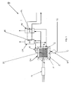
- Figure 1 shows the following components of the electrolyser 10: an electric current source P1; a central part or electrolysis module EM formed by an assembly of cells 2 where electrolysis takes place, causing the production of substances such as hydrogen and oxygen from a first substance S1; the said electrolyte, present inside the cell 2; and a container 1 of any shape, for example a substantially cylindrical shape with an axis A-A.
- a second substance S2 is located between the cell assembly 2, also called the body C, and the inner surface of the container 1, the said second substance being preferably a liquid electrical insulator.
- the electrolyser 10 is provided with a hydraulic pump WP1 for pumping the second substance S2 into the container 1 through a suitable flow channel T1.
- the container 1 is connected by means of a further flow channel T2 for the flow of the substance S2 to an overpressure device UC.
- the said device UC comprises means such as hydraulic valves, which are controlled by a control device so as to create an overpressure of the second substance S2 with respect to the pressure of the substance S1 contained in the cells 2.
- the result of the aforementioned structural configuration is a difference in pressure, P1 and P2, between the two aforementioned substances.
- the electrolyte in the cell is subjected to continuous pressure variations, causing a dynamic mechanical stress to which the various components of the body C are subjected; this unfavourable effect is overcome by the electrolysis device proposed by the invention, since the pressure acting on the individual cells is equal to the pressure difference which is controlled by the overpressure device UC in such a way that it remains constant in time.
- the electrolyser 10 also has substance separators OV and HV, provided with suitable means for separating the electrolysis products from the electrolyte, the said separators OV and HV being provided with devices comprising cooling means RR.
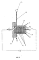
- FIG. 2 shows a side view of the electrolyser 10 proposed by the invention, with the electrolyser module EM, in which the electrolytic cells 2 forming the said module can be seen. Also visible are the container of the electrolysis module EM and the spacing seals G for providing a seal in the module.
- the electrolyser device 10 proposed by the invention comprises a container 1 of any shape, inside which is a body which contains a set of electrolytic cells C, which in this case are provided with electrodes of bipolar or monopolar configuration connected in parallel to each other, and are positioned longitudinally with respect to the axis A-A of the container 1.
- the body C is connected electrically at its ends to an electrical power source P1, particularly an appropriate transformer rectifier unit which supplies continuous electric current for the electrolysis.
- the high mechanical stability of the electrodes which are covered with a coating of synthetic insulating material for interconnecting the elements to form a set of electrolytic cells C, greatly facilitates assembly, dismantling and maintenance.
- the said set of electrolytic cells C, together with the contact electrodes E1 and E2, is called the electrolysis module EM.
- the surface of the said body C positioned longitudinally with respect to the axis A-A of the container 1, consists of electrically insulated synthetic material, particularly reinforced injection-moulded plastics, which is very strong and highly insulating.
- the first substance S1 which is located in each cell 2 is an electrolytic solution, formed for example by potash, KOH, or sodium hydroxide, NaOH, mixed with the process substance which, in the case of water electrolysis, is demineralized water.
- the hydrogen ions acquire electrons at the cathode in a reduction reaction, producing gaseous hydrogen, while in the same cell 2 the hydroxide ions undergo oxidation at the anode and give up electrons, thus forming gaseous oxygen.
- Each cell 2 is provided with the said diaphragm DF, consisting of a special porous membrane, particularly one composed of an asbestos-free synthetic material, the said membrane not permitting the passage of the gaseous substances produced at the cathode and at the anode.
- a special porous membrane particularly one composed of an asbestos-free synthetic material
- Each electrolytic cell 2 is therefore provided with a cathode on one side and an anode on the other side, and uses a first substance S1 and electric current, both supplied from suitable sources, to generate oxygen at the cathode and hydrogen at the anode; the gases produced by the electrolysis are separated by the said diaphragm DF.
- the supply voltage of the electrolyser 10 is equal to that of an individual cell multiplied by the number of cells.
- the electrolytic process of molecular decomposition of the process substances of which the substance S 1 partially consists requires constant topping up in order to provide continuity of the process.
- the topping up is carried out by providing a continuous or intermittent supply of demineralized water in proportion to the quantity decomposed by the electrolysis process.
- the second substance S2 is of the same nature as the process substance contained in S1
- S2 in the case of water electrolysis, if S2 is demineralized water, the possible reverse suction of S2 into the body C is equivalent to partially or totally topping up the substance decomposed by the electrolytic process.
- the pump WP1 together with the overpressure device UC, can be used simultaneously for maintaining the pressure P2 and for topping up the process substance.
- the topping up of the process substance through the space IT between the body C and the container 1 causes the desired flushing process in the space IT, thus maintaining the purity of the substance S2 without contamination with electrolyte S1.
- the effect of flushing the space IT can be achieved by making the substance S2 flow within IT independently of the function of topping up the process substances.
- the body 1 and the flow channels T1 and T2 are electrically insulated with respect to the electrical potential generated by P1 in the electrolysis module EM.
- the electrolyser 10 is provided with an appropriate transformer rectifier unit P1 which supplies electric current for the electrolysis process in the cells 2.
Landscapes
- Chemical & Material Sciences (AREA)
- Engineering & Computer Science (AREA)
- Chemical Kinetics & Catalysis (AREA)
- Electrochemistry (AREA)
- Materials Engineering (AREA)
- Metallurgy (AREA)
- Organic Chemistry (AREA)
- Inorganic Chemistry (AREA)
- Electrolytic Production Of Non-Metals, Compounds, Apparatuses Therefor (AREA)
Priority Applications (1)
| Application Number | Priority Date | Filing Date | Title |
|---|---|---|---|
| EP07405328A EP2060661A1 (fr) | 2007-11-16 | 2007-11-16 | Electrolyser pour produire des substances |
Applications Claiming Priority (1)
| Application Number | Priority Date | Filing Date | Title |
|---|---|---|---|
| EP07405328A EP2060661A1 (fr) | 2007-11-16 | 2007-11-16 | Electrolyser pour produire des substances |
Publications (1)
| Publication Number | Publication Date |
|---|---|
| EP2060661A1 true EP2060661A1 (fr) | 2009-05-20 |
Family
ID=39595797
Family Applications (1)
| Application Number | Title | Priority Date | Filing Date |
|---|---|---|---|
| EP07405328A Withdrawn EP2060661A1 (fr) | 2007-11-16 | 2007-11-16 | Electrolyser pour produire des substances |
Country Status (1)
| Country | Link |
|---|---|
| EP (1) | EP2060661A1 (fr) |
Citations (6)
| Publication number | Priority date | Publication date | Assignee | Title |
|---|---|---|---|---|
| US4036714A (en) * | 1972-10-19 | 1977-07-19 | E. I. Du Pont De Nemours And Company, Inc. | Electrolytic cells and processes |
| FR2608715A1 (fr) * | 1986-12-19 | 1988-06-24 | Srti Soc Rech Tech Ind | Procede de prevention de fuite de liquide, et dispositif muni de moyens de mise en oeuvre de ce procede |
| DE4418999A1 (de) | 1994-05-31 | 1995-12-07 | Von Hoerner System Gmbh | Druckelektrolyseur mit einem gekapselten Zellenblock aus einzelnen Elektrolysezellen |
| US5665211A (en) * | 1992-08-31 | 1997-09-09 | Neste Oy | Electrolysis apparatus for producing hydrogen |
| US20030094378A1 (en) * | 2001-11-16 | 2003-05-22 | Jason Shiepe | Electrochemical cell pressure regulating system and methods of using the same |
| DE102005011316A1 (de) * | 2005-03-11 | 2006-10-05 | Kaufmann, Hans, Dipl.-Ing. (FH) | Elektrolyseur und Verfahren zum Betrieb des Elektrolyseurs |
-
2007
- 2007-11-16 EP EP07405328A patent/EP2060661A1/fr not_active Withdrawn
Patent Citations (6)
| Publication number | Priority date | Publication date | Assignee | Title |
|---|---|---|---|---|
| US4036714A (en) * | 1972-10-19 | 1977-07-19 | E. I. Du Pont De Nemours And Company, Inc. | Electrolytic cells and processes |
| FR2608715A1 (fr) * | 1986-12-19 | 1988-06-24 | Srti Soc Rech Tech Ind | Procede de prevention de fuite de liquide, et dispositif muni de moyens de mise en oeuvre de ce procede |
| US5665211A (en) * | 1992-08-31 | 1997-09-09 | Neste Oy | Electrolysis apparatus for producing hydrogen |
| DE4418999A1 (de) | 1994-05-31 | 1995-12-07 | Von Hoerner System Gmbh | Druckelektrolyseur mit einem gekapselten Zellenblock aus einzelnen Elektrolysezellen |
| US20030094378A1 (en) * | 2001-11-16 | 2003-05-22 | Jason Shiepe | Electrochemical cell pressure regulating system and methods of using the same |
| DE102005011316A1 (de) * | 2005-03-11 | 2006-10-05 | Kaufmann, Hans, Dipl.-Ing. (FH) | Elektrolyseur und Verfahren zum Betrieb des Elektrolyseurs |
Similar Documents
| Publication | Publication Date | Title |
|---|---|---|
| Ding et al. | Electrochemical neutralization energy: from concept to devices | |
| KR102274666B1 (ko) | 중수의 전해농축 방법 | |
| US20210040631A1 (en) | Apparatus for alkaline water electrolysis, and gas production method | |
| US4210511A (en) | Electrolyzer apparatus and electrode structure therefor | |
| US20120103829A1 (en) | Device for the production on-demand of hydrogen by electrolysis of aqueous solutions from dry cathode | |
| JP2006518812A5 (fr) | ||
| CA2834050C (fr) | Generateur de gaz hydrogene | |
| WO2014043651A2 (fr) | Cellule électrochimique à haute pression et processus pour la réduction électrochimique de dioxyde de carbone | |
| RU2016129051A (ru) | Устройство и способ гибкого использования электроэнергии | |
| DK1274884T3 (da) | Elektrolytisk celle og fremgangsmåde til elektrolyse | |
| AU2015291762A1 (en) | A diaphragm type electrolytic cell and a process for the production of hydrogen from unipolar electrolysis of water | |
| FI79145C (fi) | Bipolaer elektrolysanordning med gasdiffusionskatod. | |
| AU2016281251A1 (en) | Water treatment system using alkaline water electrolysis device and alkaline fuel cell | |
| WO2009030203A3 (fr) | Pile électrolytique ayant une capacité électrique élevée, destinée à produire un mélange ozone-oxygène | |
| EP0104137A2 (fr) | Cellule d'électrolyse à électrode gazeuse et faible distance interélectrode | |
| Brillas et al. | Electrochemical extraction of oxygen from air via hydroperoxide ion | |
| CN114402095B (zh) | 错流式水电解 | |
| US4357224A (en) | Energy efficient electrolyzer for the production of hydrogen | |
| CN219280053U (zh) | 一种电解硫酸氢铵生产双氧水及氢气的复极式电解装置 | |
| EP2060661A1 (fr) | Electrolyser pour produire des substances | |
| KR101714601B1 (ko) | 이산화탄소의 전기화학적 환원 방법 및 장치 | |
| KR20160038363A (ko) | 이산화탄소의 전기화학적 환원 방법 및 장치 | |
| RU2007132407A (ru) | Электролизер для получения водорода и кислорода электролизом водного раствора электролита | |
| KR100414880B1 (ko) | 전기분해를 이용한 산소 및 수소 발생장치 | |
| US7914934B2 (en) | Hydro-oxy fuel generator |
Legal Events
| Date | Code | Title | Description |
|---|---|---|---|
| PUAI | Public reference made under article 153(3) epc to a published international application that has entered the european phase |
Free format text: ORIGINAL CODE: 0009012 |
|
| AK | Designated contracting states |
Kind code of ref document: A1 Designated state(s): AT BE BG CH CY CZ DE DK EE ES FI FR GB GR HU IE IS IT LI LT LU LV MC MT NL PL PT RO SE SI SK TR |
|
| AX | Request for extension of the european patent |
Extension state: AL BA HR MK RS |
|
| 17P | Request for examination filed |
Effective date: 20091030 |
|
| 17Q | First examination report despatched |
Effective date: 20091125 |
|
| AKX | Designation fees paid |
Designated state(s): AT BE BG CH CY CZ DE DK EE ES FI FR GB GR HU IE IS IT LI LT LU LV MC MT NL PL PT RO SE SI SK TR |
|
| AXX | Extension fees paid |
Extension state: RS Payment date: 20091030 Extension state: MK Payment date: 20091030 Extension state: HR Payment date: 20091030 Extension state: BA Payment date: 20091030 Extension state: AL Payment date: 20091030 |
|
| STAA | Information on the status of an ep patent application or granted ep patent |
Free format text: STATUS: THE APPLICATION IS DEEMED TO BE WITHDRAWN |
|
| 18D | Application deemed to be withdrawn |
Effective date: 20110719 |