EP2060421B1 - Shutter arrangement with lower friction in the drive - Google Patents
Shutter arrangement with lower friction in the drive Download PDFInfo
- Publication number
- EP2060421B1 EP2060421B1 EP08018219A EP08018219A EP2060421B1 EP 2060421 B1 EP2060421 B1 EP 2060421B1 EP 08018219 A EP08018219 A EP 08018219A EP 08018219 A EP08018219 A EP 08018219A EP 2060421 B1 EP2060421 B1 EP 2060421B1
- Authority
- EP
- European Patent Office
- Prior art keywords
- roller blind
- arrangement according
- linear drive
- window
- window roller
- Prior art date
- Legal status (The legal status is an assumption and is not a legal conclusion. Google has not performed a legal analysis and makes no representation as to the accuracy of the status listed.)
- Expired - Fee Related
Links
Images

Classifications
-
- B—PERFORMING OPERATIONS; TRANSPORTING
- B60—VEHICLES IN GENERAL
- B60J—WINDOWS, WINDSCREENS, NON-FIXED ROOFS, DOORS, OR SIMILAR DEVICES FOR VEHICLES; REMOVABLE EXTERNAL PROTECTIVE COVERINGS SPECIALLY ADAPTED FOR VEHICLES
- B60J1/00—Windows; Windscreens; Accessories therefor
- B60J1/20—Accessories, e.g. wind deflectors, blinds
- B60J1/2011—Blinds; curtains or screens reducing heat or light intensity
- B60J1/2013—Roller blinds
- B60J1/2036—Roller blinds characterised by structural elements
- B60J1/2041—Blind sheets, e.g. shape of sheets, reinforcements in sheets, materials therefor
-
- B—PERFORMING OPERATIONS; TRANSPORTING
- B60—VEHICLES IN GENERAL
- B60J—WINDOWS, WINDSCREENS, NON-FIXED ROOFS, DOORS, OR SIMILAR DEVICES FOR VEHICLES; REMOVABLE EXTERNAL PROTECTIVE COVERINGS SPECIALLY ADAPTED FOR VEHICLES
- B60J1/00—Windows; Windscreens; Accessories therefor
- B60J1/20—Accessories, e.g. wind deflectors, blinds
- B60J1/2011—Blinds; curtains or screens reducing heat or light intensity
- B60J1/2013—Roller blinds
- B60J1/2019—Roller blinds powered, e.g. by electric, hydraulic or pneumatic actuators
- B60J1/2027—Roller blinds powered, e.g. by electric, hydraulic or pneumatic actuators with a buckle-proof guided flexible actuating element acting on the draw bar for pushing or push-pulling, e.g. a Bowden cable
-
- B—PERFORMING OPERATIONS; TRANSPORTING
- B60—VEHICLES IN GENERAL
- B60J—WINDOWS, WINDSCREENS, NON-FIXED ROOFS, DOORS, OR SIMILAR DEVICES FOR VEHICLES; REMOVABLE EXTERNAL PROTECTIVE COVERINGS SPECIALLY ADAPTED FOR VEHICLES
- B60J1/00—Windows; Windscreens; Accessories therefor
- B60J1/20—Accessories, e.g. wind deflectors, blinds
- B60J1/2011—Blinds; curtains or screens reducing heat or light intensity
- B60J1/2013—Roller blinds
- B60J1/2036—Roller blinds characterised by structural elements
- B60J1/205—Winding tubes, e.g. telescopic tubes or conically shaped tubes
-
- B—PERFORMING OPERATIONS; TRANSPORTING
- B60—VEHICLES IN GENERAL
- B60J—WINDOWS, WINDSCREENS, NON-FIXED ROOFS, DOORS, OR SIMILAR DEVICES FOR VEHICLES; REMOVABLE EXTERNAL PROTECTIVE COVERINGS SPECIALLY ADAPTED FOR VEHICLES
- B60J1/00—Windows; Windscreens; Accessories therefor
- B60J1/20—Accessories, e.g. wind deflectors, blinds
- B60J1/2011—Blinds; curtains or screens reducing heat or light intensity
- B60J1/2013—Roller blinds
- B60J1/2036—Roller blinds characterised by structural elements
- B60J1/2052—Guides
-
- B—PERFORMING OPERATIONS; TRANSPORTING
- B60—VEHICLES IN GENERAL
- B60J—WINDOWS, WINDSCREENS, NON-FIXED ROOFS, DOORS, OR SIMILAR DEVICES FOR VEHICLES; REMOVABLE EXTERNAL PROTECTIVE COVERINGS SPECIALLY ADAPTED FOR VEHICLES
- B60J1/00—Windows; Windscreens; Accessories therefor
- B60J1/20—Accessories, e.g. wind deflectors, blinds
- B60J1/2011—Blinds; curtains or screens reducing heat or light intensity
- B60J1/2013—Roller blinds
- B60J1/2066—Arrangement of blinds in vehicles
- B60J1/2069—Arrangement of blinds in vehicles of multiple blinds, e.g. more than one blind per window or per actuation system
-
- B—PERFORMING OPERATIONS; TRANSPORTING
- B60—VEHICLES IN GENERAL
- B60J—WINDOWS, WINDSCREENS, NON-FIXED ROOFS, DOORS, OR SIMILAR DEVICES FOR VEHICLES; REMOVABLE EXTERNAL PROTECTIVE COVERINGS SPECIALLY ADAPTED FOR VEHICLES
- B60J1/00—Windows; Windscreens; Accessories therefor
- B60J1/20—Accessories, e.g. wind deflectors, blinds
- B60J1/2011—Blinds; curtains or screens reducing heat or light intensity
- B60J1/2013—Roller blinds
- B60J1/2066—Arrangement of blinds in vehicles
- B60J1/2075—Arrangement of blinds in vehicles specially adapted for fixed windows
- B60J1/2083—Arrangement of blinds in vehicles specially adapted for fixed windows for side windows, e.g. quarter windows
-
- B—PERFORMING OPERATIONS; TRANSPORTING
- B60—VEHICLES IN GENERAL
- B60J—WINDOWS, WINDSCREENS, NON-FIXED ROOFS, DOORS, OR SIMILAR DEVICES FOR VEHICLES; REMOVABLE EXTERNAL PROTECTIVE COVERINGS SPECIALLY ADAPTED FOR VEHICLES
- B60J1/00—Windows; Windscreens; Accessories therefor
- B60J1/20—Accessories, e.g. wind deflectors, blinds
- B60J1/2011—Blinds; curtains or screens reducing heat or light intensity
- B60J1/2013—Roller blinds
- B60J1/2066—Arrangement of blinds in vehicles
- B60J1/2086—Arrangement of blinds in vehicles specially adapted for openable windows, e.g. side window
-
- B—PERFORMING OPERATIONS; TRANSPORTING
- B60—VEHICLES IN GENERAL
- B60J—WINDOWS, WINDSCREENS, NON-FIXED ROOFS, DOORS, OR SIMILAR DEVICES FOR VEHICLES; REMOVABLE EXTERNAL PROTECTIVE COVERINGS SPECIALLY ADAPTED FOR VEHICLES
- B60J3/00—Antiglare equipment associated with windows or windscreens; Sun visors for vehicles
- B60J3/002—External sun shield, e.g. awning or visor
- B60J3/005—External sun shield, e.g. awning or visor for side windows
Landscapes
- Engineering & Computer Science (AREA)
- Mechanical Engineering (AREA)
- Operating, Guiding And Securing Of Roll- Type Closing Members (AREA)
Description
Gelegentlich müssen bei Fahrzeugen zwei Rollos eines Fensters gemeinsam über eine Antriebseinrichtung angetrieben werden. Ein Beispiel für eine solche Beschattungsanordnung findet sich beispielsweise an den hinteren Seitenfenstern. Diese sind in einem im Wesentlichen rechteckigen Teil und einen etwa dreieckförmigen Teil unterteilt. In dem rechteckigen Teil befindet sich die versenkbare Scheibe der Seitentür während der dreieckförmige Teil starr ist. Die beiden Abschnitte des Fensters werden durch eine Fensterstrebe voneinander getrennt.Occasionally in vehicles two blinds of a window must be driven together via a drive device. An example of such a shading arrangement can be found, for example, at the rear side windows. These are divided into a substantially rectangular part and an approximately triangular part. In the rectangular part is the retractable disc of the side door while the triangular part is rigid. The two sections of the window are separated by a window strut.
Die Rolloanordnungen, die für solche Seitenfenster vorgesehen sind, bestehen aus einer horizontalen Wickelwelle für den rechteckigen Teil und einer vertikal angeordneten Wickelwelle für den dreieckförmigen Teil. Die Wickelwelle für den dreieckförmigen Teil befindet sich bei der Fensterstrebe.The roller blind arrangements which are provided for such side windows consist of a horizontal winding shaft for the rectangular part and a vertically arranged winding shaft for the triangular part. The winding shaft for the triangular part is located at the window strut.
Die Rollobahn für das horizontale Fenster ist mit einem Zugstab verbunden, der beidends in Führungsschienen geführt ist. Diese Führungsschiene dienen gleichzeitig zur ausknicksicheren Führung von linienförmigen Schubgliedern. Diese laufen in Führungsrohren zu einer Antriebseinrichtung in Gestalt eines Getriebemotors mit Stirnzahnrad auf der Ausgangswelle. Das Stirnzahnrad kämmt mit der Verzahnung der linienförmigen Schubglieder. Für das nichtbenutzte Leertrum jedes Schubglieds ist zusätzlich noch ein Speicherrohr vorhanden.The roller blind for the horizontal window is connected to a pull rod, which is guided at both ends in guide rails. This guide rail also serve for ausknicksicheren leadership of linear push members. These run in guide tubes to a drive device in the form of a geared motor with spur gear on the output shaft. The spur gear meshes with the teeth of the linear thrust links. For the unused empty section of each push element, a storage tube is additionally available.
Der Zugstab des dreieckförmigen Rollos ist einends in einer Führungsschiene geführt, die ebenfalls horizontal unterhalb der Fensterbrüstung verläuft. Bei den bekannten Anordnungen führt von dieser Führungsschiene ein s- oder Z-förmig gekrümmtes Führungsrohr zu demselben Antriebsmotor, um den Antrieb für das dreieckförmige Rollo zu erreichen.The tension rod of the triangular roller blind is guided at one end in a guide rail, which also runs horizontally below the window sill. In the known arrangements of this guide rail leads an s- or Z-shaped guide tube to the same drive motor to achieve the drive for the triangular blind.
Während die Führungsrohre für das rechteckige Fensterrollo nur eine Krümmung aufweisen und demzufolge relativ wenig Reibung erzeugen, verläuft das Führungsrohr für das dreieckförmige Fenster wegen der doppelten gegenseitigen Krümmung sehr kompliziert und erzeugt extrem viel Reibung.While the guide tubes for the rectangular window blind only have a curvature and consequently generate relatively little friction, the guide tube for the triangular window is very complicated because of the double mutual curvature and generates extremely much friction.
Die
Ausgehend hiervon ist es Aufgabe der Erfindung eine Rolloanordnung zu schaffen, bei der weniger verlustreibung auftritt.Based on this, it is an object of the invention to provide a roller blind, in which less loss of friction occurs.
Diese Aufgabe wird erfindungsgemäß durch die Rolloanordnung mit den Merkmalen des Anspruches 1 gelöst.This object is achieved by the roller blind arrangement with the features of claim 1.
Zu der neuen Fensterrolloanordnung gehören eine erste und eine zweite Wickelwelle, die, jede für sich, drehbar gelagert sind. Mit der ersten Wickelwelle ist eine erste Rollobahn verbunden, deren freie Kante an einem zugehörigen ersten Zugstab befestigt ist. Die zweite Rollobahn ist an der zweiten Wickelwelle verankert und ebenfalls mit einem zugehörigen zweiten Zugstab verbunden. Um die erste Rollobahn zu bewegen ist eine Antriebseinrichtung mit Ausgangszahnrad vorgesehen, das mit wenigstens einem ersten linienförmigen Antriebsmittel formschlüssig kämmt. Dadurch kann die erste Rollobahn mit Hilfe des Antriebsmittels über die Antriebseinrichtung bewegt werden.To the new window blind assembly include a first and a second winding shaft, which are rotatably mounted, each by itself. With the first winding shaft, a first roller blind is connected, the free edge is attached to an associated first tie rod. The second roller blind is anchored to the second winding shaft and also connected to an associated second pull rod. In order to move the first roller blind a drive device is provided with output gear, which meshes with a form-fitting manner with at least one first linear drive means. Thereby, the first roller blind can be moved by means of the drive means via the drive means.
Die Bewegung für die zweite Rollobahn wird aus der Bewegung des ersten linienförmigen Antriebmittels abgeleitet. Hierzu ist das erste linienförmige Antriebsmittel getrieblich mit einer lose drehbaren Zahnradanordnung gekuppelt mit der auch ein zweites linienförmiges Antriebsmittel kämmt.The movement for the second roller blind is derived from the movement of the first linear drive means. For this purpose, the first linear drive means is coupled by means of a gear with a loosely rotatable gear arrangement which also meshes with a second linear drive means.
Dieses neue erfinderische Konzept ermöglicht es, ein weiteres langes Führungsrohr einzusparen, das sonst erforderlich wäre, um das zweite linienförmige Antriebsmittel bis zur Antriebseinrichtung zu führen.This new inventive concept makes it possible to save another long guide tube, which would otherwise be required to guide the second linear drive means to the drive means.
Übertragen auf ein Seitenfenster bei einem Kraftfahrzeug kann die Anordnung beispielsweise derart gestaltet sein, dass die erste Rollobahn der Rollobahn für das viereckige Fenster entspricht, wobei der Zugstab in zwei endseitigen Führungsschienen geführt ist. Jede Führungsschiene führt ein erstes linienförmiges Antriebsmittel, das über ein Führungsrohr bis hin zur Antriebseinrichtung geführt ist. Die Bewegung für das dreieckförmige Rollo wird aus der Bewegung jenes Schubglieds abgeleitet, dass bei der Fensterstrebe läuft, die die beiden Fensterabschnitte voneinander trennt. Die Bewegung des dreieckförmigen Rollos geschieht über ein linienförmiges Antriebsmittel, das auf diese Weise nur mittelbar mit der Antriebseinrichtung gekuppelt ist. Die Führungsschiene für das dreieckförmige Rollo verläuft horizontal unterhalb der Fensterunterkante und somit im rechten Winkel zu der Führungsschiene an der Fensterstrebe.Transferred to a side window in a motor vehicle, the arrangement may be designed, for example, such that the first roller blind corresponds to the roller blind for the quadrangular window, wherein the pull rod is guided in two end guide rails. Each guide rail guides a first linear drive means, which is guided over a guide tube up to the drive device. The movement for the triangular blind is derived from the movement of that push member that runs at the window strut separating the two window sections. The movement of the triangular roller blinds takes place via a line-shaped drive means, which in this way is coupled only indirectly to the drive device. The guide rail for the triangular roller blind runs horizontally below the lower edge of the window and thus at right angles to the guide rail on the window strut.
Die Zahnradanordnung sitzt in der Innenecke an der Stelle, an der sich das linienförmige Antriebsmittel für das dreieckförmige Rollo mit dem linienförmigen Antriebsmittel, das bei der Fensterstrebe geführt ist, schneiden.The gear assembly is seated in the inner corner at the point where the linear drive means for the triangular blind with the linear drive means, which is guided at the window strut, cut.
Aus diesem Grund ist kein langes Führungsrohr für das dreieckförmige Fensterrollo mehr erforderlich. Das Antriebsmittel für das dreieckförmige Rollo läuft im Wesentlichen nur horizontal, so dass hier praktisch keine nennenswerten Reibungskräfte auftreten. Insbesondere ist der Hub für das dreieckförmige Fensterrollo deutlich kürzer als die Breite des viereckigen Rollos, womit es möglich ist, unmittelbar in der Verlängerung der Führungsschiene für das dreieckförmige Fensterrollo auch das Speicherrohr unterzubringen. Die Reibungskräfte sind deutlich vermindert. Außerdem ist der Fertigungsaufwand wesentlich reduziert, weil kein weiteres Führungsrohr gebogen werden muss, das nach dem Stand der Technik die Führungsschiene für das dreieckförmige Fensterrollo mit der Antriebseinrichtung verbindet.For this reason, no longer guide tube for the triangular window blind is required. The drive means for the triangular roller blind runs essentially only horizontally, so that practically no significant frictional forces occur here. In particular, the stroke for the triangular window roller blind is significantly shorter than the width of the quadrangular roller blind, which makes it possible to accommodate the storage tube directly in the extension of the guide rail for the triangular window roller blind. The frictional forces are significantly reduced. In addition, the production cost is significantly reduced, because no further guide tube must be bent, which connects the guide rail for the triangular window blind with the drive device according to the prior art.
Die erfindungsgemäße Anordnung eignet sich insbesondere, wie sich aus der obigen Erläuterung ergibt, für Fensterrolloanordnungen, bei denen die Wickelwelle im Winkel zueinander angeordnet sind.The arrangement according to the invention is particularly suitable, as can be seen from the above explanation, for window blind arrangements in which the winding shaft is arranged at an angle to one another.
Die Antriebseinrichtung kann von einem elektrischen Getriebemotor gebildet sein, wobei das Ausgangszahnrad auf der Ausgangswelle des Getriebemotors drehfest sitzt.The drive device may be formed by an electric geared motor, wherein the output gear rotatably seated on the output shaft of the geared motor.
Die linienförmigen Antriebmittel können die Gestalt einer Zahnstange haben. Vorteilhafterweise handelt sich um eine rundumverzahnte Zahnstange, beispielsweise eine schräg verzahnte Zahnstange. Das linienförmige Antriebsmittel kann auch als Lochband ausgeführt sein.The linear drive means may take the form of a rack. Advantageously, is a toothed rack around, for example, a helical rack. The linear drive means can also be designed as a perforated belt.
Bei der neuen Fensterrolloanordnung können entweder für die erste oder für die zweite Rollobahn, je nachdem welche als erste angesehen wird, zwei linienförmige Antriebsmittel vorhanden sein.In the new window roller blind arrangement, two line-shaped drive means can be used either for the first or for the second roller blind, whichever is considered first to be available.
Die linienförmigen Antriebsmittel können so gestaltet sein, dass sie beim Ausfahren des Rollos auf Druck belastet werden.The linear drive means can be designed so that they are subjected to pressure when extending the roller blind.
Zum Führen des Zugstabs kann diesem wenigstens eine Führungsschiene zugeordnet sein.To guide the tension rod can be assigned to this at least one guide rail.
Die Führungsschiene kann zur ausknicksicheren Führung des zugeordneten linienförmigen Antriebsmittels eingerichtet sein.The guide rail can be configured for kink-proof guidance of the associated linear drive means.
Der ersten und/oder der zweiten Wickelwelle kann ein Federmotor zugeordnet sein.The first and / or the second winding shaft may be associated with a spring motor.
Die lose drehbare Zahnradanordnung kann von einem einzigen Zahnrad gebildet sein, oder aber von einer Zahnradanordnung, die zwei drehfest miteinander gekuppelte Zahnräder umfasst. Jedes der beiden Zahnräder ist mit einem der linienförmigen Antriebsmittel gekuppelt.The loose rotatable gear assembly may be formed by a single gear, or by a gear assembly comprising two rotatably coupled together gears. Each of the two gears is coupled with one of the linear drive means.
Das Zahnrad mit dem kleinsten Durchmesser kann mit jenem linienförmigen Antriebsmittel gekuppelt sein das die Rollobahn mit dem kleineren Hub betätigt.The gear with the smallest diameter can be coupled with that linear drive means which actuates the roller blind with the smaller stroke.
Im Übrigen sind Weiterbildungen der Erfindung Gegenstand von Unteransprüchen.Incidentally, developments of the invention are the subject of subclaims.
Die nachfolgende Figurenbeschreibung erläutert Aspekte zum Verständnis der Erfindung. Weitere nicht beschriebene Details kann der Fachmann in der gewohnten Weise den Figuren entnehmen, die insoweit die Figurenbeschreibung ergänzen. Es ist klar dass eine Reihe von Abwandlungen möglich sind.The following description of the figures explains aspects for understanding the invention. Other details not described, the expert can refer to the figures in the usual way, the extent to complement the description of the figures. It It is clear that a number of modifications are possible.
Die nachfolgenden Figuren sind nicht unbedingt maßstäblich. Zur Veranschaulichung von Details können möglicherweise bestimmte Bereiche übertrieben groß dargestellt sein. Darüber hinaus sind die Zeichnungen plakativ vereinfacht und enthalten nicht jedes bei der praktischen Ausführung gegebenenfalls vorhandene Detail. Die Begriffe "oben" und "unten" bzw. "vorne" und "hinten" sowie "links" und "rechts" beziehen sich auf die normale Einbaulage bzw. die Terminologie bei Kraftfahrzeugen.The following figures are not necessarily to scale. To illustrate details, certain areas may be exaggerated. Moreover, the drawings are simplistically simplified and do not include any detail that may be present in the practice. The terms "top" and "bottom" or "front" and "rear" as well as "left" and "right" refer to the normal installation position or terminology in motor vehicles.
In der Zeichnung ist ein Ausführungsbeispiel des Gegenstandes der Erfindung dargestellt.
- Fig. 1
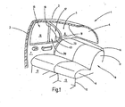
- zeigt den aufgebrochenen Fondbereich eines Pkw un- ter Veranschaulichung des rechten Seitenfensters.
- Fig. 2
- veranschaulicht in einer schematischen Darstellung das Antriebskonzept des erfindungsgemäßen Fenster- rollos.
- Fig. 1
- shows the broken-up rear area of a car under the illustration of the right-hand side window.
- Fig. 2
- illustrated in a schematic representation of the drive concept of the window blind invention.
Der veranschaulichte Karosserieabschnitt 1 weist ein Dach 2 auf, von dem seitlich eine B-Säule 3 nach unten zu einer nicht gezeigten Bodengruppe führt. Eine entsprechende B-Säule wäre auf der weggebrochenen Seite des Fahrzeugs zu denken. Das Dach 2 geht an seiner Hinterkante in ein Heckfenster 4 über. Seitlich endet das Heckfenster 4 an einer C-Säule 5, die sich im Abstand zu der B-Säule 3 befindet. Die C-Säule trägt eine Innenverkleidung 6.The illustrated body section 1 has a
Zwischen der B-Säule und der C-Säule ist an der B-Säule eine hintere rechte Seitentür in der bekannten Weise anscharniert.Between the B-pillar and the C-pillar, a rear right side door is hinged to the B-pillar in the known manner.
Auf der Höhe der hinteren rechten Seitentür befindet sich eine Rücksitzbank 8 zu der eine Sitzfläche 9 sowie eine Rücksitzlehne 11 gehören. Die Rücksitzfläche 9 liegt auf einer Sockelfläche 12, die zu der Bodengruppe gehört und vor der Fußräume 13 ausgebildet sind.At the height of the rear right side door is a rear seat 8 to which a seat 9 and a rear seat back 11 belong. The rear seat 9 lies on a
Auf Höhe der Oberkante der Rücksitzlehne 11 erstreckt sich eine Hutablage 14 zu der Unterkante der Heckscheibe 4.At the height of the upper edge of the rear seat back 11, a
Die hintere rechte Seitentür 7 ist in der für Limousinen üblichen Weise mit einem Seitenfenster 15 versehen. Das Seitenfenster 15 gliedert sich in einen ersten Fensterabschnitt 16 sowie einen hinteren zweiten Fensterabschnitt 17. Der erste Fensterabschnitt 16 hat eine im Wesentlichen rechteckige Gestalt und wird nach hinten von einer Führungssäule 18 begrenzt, die gleichzeitig eine Kante des zweiten Fensterabschnitts 17 darstellt. Der zweite Fensterabschnitt 17 wird gegenüber der Führungssäule 18 von einem Türrahmen 19 begrenzt, der zusammen mit der Führungssäule 17 die Gestalt des zweiten Fensterabschnitts 16 festlegt. Er ist, wie dargestellt, etwa dreieckförmig.The rear
Dem Fenster 15 ist ein Seitenfensterrollo 20 zugeordnet. Der prinzipielle Aufbau des Seitenfensterrollos 20 ist in
Das Teilrollo 23 dient der Abschattung des rechteckigen Bereiches 16 während das Fensterrollo 24 zur Abschattung des dreieckförmigen Abschnittes 17 dient.The partial blind 23 serves to shade the
Zu dem Fensterrollo 23 gehört eine Wickelwelle 25, die unterhalb der Fensterunterkante 2 in dem Türkorpus 21 gelagert ist. Die Wickelwelle 25 liegt parallel zur Fensterunterkante. An der Wickelwelle 25 ist eine Rollobahn 26 mit einer Kante befestigt, deren andere Kante 27 an einem Zugstab 28 befestigt ist. Im Inneren der wickelwelle 25 befindet sich ein an sich bekannter Federmotor, der dazu eingerichtet ist, die Wickelwelle im Sinne des Aufwicklns der Rollobahn 26 auf die Wickelwelle 25 vorzuspannen.To the
Der Zugstab 28 ist in zwei seitlichen Führungsschienen 29 und 31 geführt. Die Führungsschienen 29 und 31 laufen neben den seitlichen vertikalen Fensterkanten des Fensterabschnitt 16. Das heißt die Führungsschiene 29 befindet sich im linken vertikalen Abschnitt des Fensterrahmens 19 während die Führungsschiene 31 in der Führungsrolle 18 untergebracht ist.The
Beide Führungsschienen 29, 31 reichen bis unter die Fensterunterkante 22 bis in die Türzarge 21 hinein. Am unteren Ende der Führungsschiene 29 schließt sich ein Führungsrohr 32 an, das zu einem Getriebegehäuse 33 eines Getrieberotors 34 führt. Mit dem Führungsrohr 32 fluchtet auf der anderen Seite des Getriebegehäuses 33 ein Speicherrohr 35.Both
An die Führungsschiene 31 ist an der Unterseite ein Zwischengetriebe 36 angeschlossen, dessen Aufbau in Verbindung mit
Von dem Zwischengetriebe 36 führt ein Führungsrohr 37 zu dem Getriebegehäuse 33 des Antriebsgetriebemotors 34. Auf der gegenüberliegenden Seite fluchtet mit dem Führungsrohr 37 ein Speicherrohr 38.From the
Zu dem Fensterrollo 24 gehört ein unterhalb der Fehnsterunterkante 22 angeordnete Führungsschiene 39, die von dem Zwischengetriebe 36 ausgeht.To the
Neben der Führungsschiene 31 ist auf der Führungssäule 19 eine weitere Wickelwelle 41 drehbar gelagert, an der mit einer Kante eine dreieckförmige Rollobahn 42 befestigt ist. Die Wickelwelle 41 enthält einen an sich bekannten Federmotor ähnlich wie die Wickelwelle 25, um die Wickelwelle 41 mit einem Drehsinn vorzuspannen, der bestrebt ist, die Rollobahn 42 auf die Wickelwelle 41 aufzuwickeln. An der Spitze der Rollobahn 42 befindet sich ein kleines Konturteil 43, das an einem Arm 44 befestigt ist, der in die Führungsschiene 39 hinein ragt.In addition to the
Die geführten linienförmigen Schubgliedern in Gestalt von rundum verzahnten flexiblen Zahnstangen. Von diesen Schubglieder sind in
Jedes der beiden Zugglieder 45 und 46 besteht aus einer zylindrischen Seele 47, um die sich schraubenförmig eine Rippe 48 herum windet, die mit der Seele 47 fest verbunden ist. Dazu entsteht eine Art rundum verzahnte flexible Zahnstange. Mit Hilfe der Rippe 48 kann eine Schub- oder Druckkraft auf die Seele 47 übertragen werden.Each of the two
Das Zwischengetriebe 36 weist ein Gehäuse 51 auf, dass zwei rechtwinklige zueinander verlaufende Durchgangsbohrungen 52 und 53 enthält. Die beiden Durchgangsbohrungen 52 und 53 sind seitlich gegeneinander versetzt, so dass sie einander nicht schneiden. Der Durchmesser der Durchgangsbohrungen 52 und 53 entspricht dem Außendurchmesser der Schubglieder 45, 46 gemäß über der Scheitellinie der Rippe 48.The
Im Bereich der Innenecke, die von den beiden Durchgangsbohrungen 52 und 53 gebildet ist, befindet sich eine Kammer 54, in der eine Zahnradanordnung auf einer Achse 56 drehbar gelagert ist. Die Achse 56 steht senkrecht auf zwei zueinander parallele Ebenen, von denen die eine die Achse der Durchgangsbohrung 52 und die andere die Achse der Durchgangsbohrung 53 enthält.In the region of the inner corner, which is formed by the two through
Die Zahnradanordnung 55 enthält ein großes Zahnrad 57 sowie ein kleineres Zahnrad 58. Beide Zahnräder 57 und 58 sind Stirnzahnräder und mit eiern Verzahnung auf der Außenumfangsfläche versehen, so das sich mit der Rippe 58 der 45 bzw. 46 kämmen können. Die beiden Zahnräder 57 und 58 sind koaxial drehfest miteinander verbunden. Die Achse 56 ist so gelegen, dass die Zahnradstirn des groOen Zahnrads 57 in die Durchgangsbohrung 53 eintaucht, um dort, wie gezeigt, mit der Schubglied 45 in Eingriff zu kommen. Außerdem ist die Achse 56 so gelegen, dass das kleinere Zahnrad 58 in die Durchgangsbohrung 52 eintauchen kann damit die Zahnradstirn des Stirnzahnrades 58 mit dem Schubglied 46 formschlüssig klemmen kann.The
In Verlängerung der Durchgangsbohrung 52 ist nach hinten die Führungsschiene 39 angeschlossen, während in der entgegengesetzten Richtung ein Speicherrohr 59 angeschlossen ist, dass das Leertrum des Schubglieds 46 aufnimmt.In extension of the through
Die Führungsschiene 39 enthält eine Führungsnut 61. Der Querschnitt der Führungsnut 61 setzt sich aus einer zylindrischen Führungskammer 62 und einen rechteckigen Schlitz 63 zusammen, dessen Weite kleiner ist als der Durchmesser der Nutenkammer 62. Dadurch entsteht eine hinterschnittene Führungsnut 61, in der ein Gleitstein 64 geführt ist, mit dem der Arm 44 verbunden ist. Die Weite des Schlitzes 63 entspricht der Dicke des Armes 44.The
An das Getriebegehäuse 51 schließt sich in Verlängerung der geraden Durchgangsbohrung 53 nach oben die Führungsschiene 31 und nach unten das Führungsrohr 37 an. Die Führungsschiene 31 sowie die Führungsschiene 29 haben dasselbe Querschnittsprofil hinsichtlich der Führungsnut, wie diese im Zusammenhang mit der Führungsnut 61 der Führungsschiene 39 erläutert ist.The
Die Funktionsweise des beschriebenen Seitenfensterrollos ist wie folgt:The operation of the described side window blinds is as follows:
Im eingefahrenen Zustand sind die beiden Rollobahnen 26 und 42 unter Wirkung der Federmotoren auf die zugehörige Wickelwelle 25, 41 aufgewickelt. Dies ist möglich, weil die Schubglieder die in den Führungsschienen 29 und 31 laufen, d.h. das Schubglied 45 und das dem Schubglied 45 entsprechende Schubglied in der Führungsschiene 29 weitgehend zurückgezogen sind, wobei das Leertrum in dem jeweiligen Speicherrohren 35, 38 aufgenommen ist.In the retracted state, the two
Außerdem ist das Schubglied 46 aus der Führungsschiene 39 zurückgezogen, so dass auch hier das Aufwickeln der Rollobahn 42 auf die Wickelwelle 41 von dem Schubglied 41 nicht behindert wird.In addition, the thrust member 46 is withdrawn from the
Wenn der Benutzer ausgehend von der eingefahrenen Stellung das Rollo ausfahren will, setzt ein nicht gezeigter Schalter den Getriebemotor 34 in Gang. Dieser treibt ein Zahnrad an, das mit dem Schubgliedern für das Fensterrollo 23 kämmend in Eingriff steht. Es zieht die zugehörigen Schubglieder aus den Speicherrohren 35 und 38 heraus und schiebt sie in Richtung auf das obere Ende der Führungsschienen 28 und 31 vor. Dabei drücken die beiden Schubglieder, nämlich das Schubglied 45 in dem in der Führungsschiene 31 und das Schubglied in der Führungsschiene 29, den Auszugsstab 28 vor sich her nach oben, wodurch die Rollobahn 26 gegen die Wirkung des Federmotors von der Wickelwelle 25 abgewickelt wird.If the user wants to extend the roller blind, starting from the retracted position, a switch (not shown) activates the geared
Auf eine Darstellung des Schubglieds in der Führungsschiene 29 kann verzichtet werden. Dieses Schubglied entspricht in seinem Aufbau dem Schubglied 45 aus
Die Antriebsbewegung zum Ausfahren der rollobahn 42 wird aus der Bewegung des Schubglieds 45 abgeleitet, dass das rechte oder hintere Ende des Zugstabs 28 des Fensterrollos 23 antreibt. Durch die Aufwärtsbewegung des Schubglieds 45 beim Ausfahren der Rollobahn 26 wird die zahnradanordnung 55 im Uhrzeigersinn in Umdrehung versetzt. Die Drehbewegung ist schlupffrei, weil das Zahnrad 57 formschlüssig mit der Rippe 48 des Schubglieds 45 in Eingriff steht.The drive movement for extending the
Da die beiden Zahnräder 57 und 58 drehfest miteinander verbunden sind, wird auch gleichzeitig das Zahnrad 58 im Uhrzeigersinn im Umdrehung versetzt und schiebt somit das Schubglied 46 bezogen auf
Das Einfahren geschieht sinngemäß in der umgekehrten Richtung. Der Benutzer setzt den Getriebemotor 34 mit der entgegengesetzten Drehbewegung in Gang, wodurch die Schubglieder aus den beiden Führungsschienen 29 und 31 zurückgezogen werden. Die Abwärtsbewegung des Druckglieds 45 dreht die Zahnradanordnung 55 im gegenuhrzeigersinn was dazu führt, dass das Schubglied 46 aus der Führungsschiene 39 zurückgezogen wird. Die Federmotoren in den Wickelwellen 25 und 41 können die zugehörigen Rollobahnen 26 und 62 auswickeln in dem Maße, indem diese die Schubglieder zulassen.The retraction happens analogously in the opposite direction. The user actuates the
Wie die schematische Darstellung in
Sinngemäß das Gleiche gilt für die Speicherrohre 35 und 38, die ebenfalls zwischen den Einbauten innerhalb des Türkorpus 21 sich hindurch winden müssen.Analogously, the same applies to the
Je stärker die Führungsrohre oder Speicherrohre für die Schubglieder gekrümmt und gewunden verlaufen, um so größer wird der Reibungsverlust darin. Im Gegensatz zum Stand der Technik wird für den Antrieb des dreieckförmuigen hinteren Rollos 24 nicht etwa ein weiteres Führungsrohr verwendet, das die Führungsschiene 39 mit dem Getriebemotor 34 verbindet. Ein solches Führungsrohr muss z-förmig oder s-förmig gebogen werden und erzeugt entsprechend sehr viel Reibung. Bei der Erfindung wird statt dessen die Bewegung für das Schubglied 46 aus der Bewegung des Schubglieds 45 abgeleitet, womit es möglich wird, die Antriebsquelle für das Schubglied 46 in Gestalt des Zwischengetriebes 51 an einer Stelle zu platzieren, die ein praktisch gestreckten Verlauf des Schubglieds 46 ermöglicht. Das Schubglied 46 läuft gerade in die Führungsschiene 39 ein und auch das Speicherrohr 59 das das Leertrum des Schubglieds 46 aufnimmt, kann in gerader Richtung unterhalb der Fensterunterkante 22 verlaufend angeordnet sein. Die Reibung, die das Schubglied 46 in der Führungsschiene 39 bzw. dem Speicherrohr 59 erfährt, wird dadurch minimal.The more the guide tubes or storage tubes for the thrust members are curved and twisted, the greater the friction loss therein. In contrast to the prior art, not another guide tube is used to drive the triangular
Die Verminderung der Reibungskräfte bei dem Schubglied 46 zum Antrieb des dreieckförmigen hinteren Fensterrollos 24 bringt auch den Vorteil mit sich, dass der Einklemmschutz besser zu realisieren ist. Der Einklemmschutz wird in der Regel dadurch erreicht, dass der Strom für den Motor im Ausfahrbetrieb überwacht wird. Je höher die Reibungsverluste sind, um so größer ist der Motorstrom auch bei ordnungsgemäß laufendem Rollo, so dass eine Differenzierung zwischen frei laufendem Rollo und eingeklemmten Körperteilen schwierig wird. Wenn hingegen die Reibung klein ist, ist der Einklemmschutz mit Hilfe einer Stromüberwachung leichter zu bewerkstelligen.The reduction of the frictional forces in the thrust member 46 for driving the triangular
Wie für den Fachmann unschwer zu erkennen ist, sind die beiden Zahnräder 57 und 58 in ihrem Wirkdurchmesser so bemessen, dass sie dem unterschiedlichen Hub der Rollobahn 26 im Verhältnis zur Rollobahn 42 Rechnung tragen.As will be readily apparent to those skilled in the art, the two
Eine Seitenfensterrollo für ein Kraftfahrzeug setzt sich aus zwei Rollos zusammen. Das eine Teilrollo wird zum Abschatten des dreieckförmigen Bereiches verwendet und das andere zum Abschatten des viereckförmigen Bereich. Zum Ausfahren der Rollobahn werden ausknicksicher geführte Schubglieder verwendet. Die Bewegung des Schubglieds für das dreieckförmige Rollo wird aus der Bewegung des benachbarten Schubglieds für das rechteckige Rollo abgeleitet. Dadurch werden komplizierte verlegte Führungsrohre für das Schubglied des dreieckförmigen Rollos vermieden.A side window roller blind for a motor vehicle is composed of two blinds. One partial blind is used for shading the triangular area and the other for shading the quadrangular area. To extend the roller blind ausknicksicher guided push elements are used. The movement of the thrust member for the triangular blind is derived from the movement of the adjacent thrust member for the rectangular blind. As a result, complicated laid guide tubes for the thrust member of the triangular blinds are avoided.
Claims (16)
- Window roller blind arrangement for motor vehicles
with a first winding shaft (25, 41), which is rotatably mounted,
with a first blind sheet (26), which is fastened to the first winding shaft (25) and is connected to a first pull rod (27),
with a drive means (34), which has a drive gear wheel,
with at least one first linear drive element (45), which connects the output gear wheel of the drive means (34) to the first pull rod (27),
with a second winding shaft (41), which is rotatably mounted,
with a second blind sheet (42), which is fastened to the second winding shaft (41) and is connected to a second pull rod (43),
characterised by a loose rotatable gear wheel arrangement (55), which meshes positively with the first linear drive elements (45), and
at least one second linear drive element (46), which meshes positively with the loose rotatable gear wheel arrangement (55) in order to couple the loose rotatable gear wheel arrangement (55) to the second blind sheet (42). - Window roller blind arrangement according to claim 1, characterised in that it is dimensioned for a divided side window (15).
- Window roller blind arrangement according to claim 1, characterised in that the two winding shafts (25, 41) are arranged at an angle to one another.
- Window roller blind arrangement according to claim 1, characterised in that the drive means (34) comprises a geared motor, wherein the drive gear wheel is coupled to the output shaft of the geared motor or sits thereon.
- Window roller blind arrangement according to claim 1, characterised in that the first and/or the second linear drive element (45, 46) has the structure of a toothed rack.
- Window roller blind arrangement according to claim 1, characterised in that the first and/or the second linear drive element (45, 46) has the structure of a toothed rack with full tooth system.
- Window roller blind arrangement according to claim 1, characterised in that the first and/or the second linear drive element (45, 46) is a perforated band.
- Window roller blind arrangement according to claim 1, characterised in that there are two first linear drive elements (45).
- Window roller blind arrangement according to claim 1, characterised in that the linear drive elements (45, 46) are subjected to pressure when the roller blind is extended.
- Window roller blind arrangement according to claim 1, characterised in that the linear drive elements (45, 46) are guided, at least in sections, in a buckle-resistant manner.
- Window roller blind arrangement according to claim 1, characterised in that the first and/or the second pull rod (27, 43) has at least one associated guide rail (29, 32, 39).
- Window roller blind arrangement according to claim 11, characterised in that the guide rail (29, 32, 39) serves to guide the associated linear drive element (45, 46) in a buckle-resistant manner.
- Window roller blind arrangement according to claim 1, characterised in that the first and/or the second winding shaft (25, 41) can be driven by means of an associated spring motor.
- Window roller blind arrangement according to claim 1, characterised in that the loose rotatable gear wheel arrangement (55) is formed by a single gear wheel.
- Window roller blind arrangement according to claim 1, characterised in that the loose rotatable gear wheel arrangement (55) has two gear wheels (57, 58), which are coupled to one another to be fixed against rotation and of which one gear wheel (57, 58) is coupled to one linear drive element (45, 46) and the other gear wheel (57, 58) is coupled to the other linear drive element (45, 46).
- Window roller blind arrangement according to claim 15, characterised in that the gear wheel (58) with the smaller diameter is coupled to the linear drive element (46), which actuates the blind sheet (42) with a smaller stroke.
Applications Claiming Priority (1)
| Application Number | Priority Date | Filing Date | Title |
|---|---|---|---|
| DE102007054694A DE102007054694A1 (en) | 2007-11-14 | 2007-11-14 | Roller blind with reduced friction in the drive forks |
Publications (2)
| Publication Number | Publication Date |
|---|---|
| EP2060421A1 EP2060421A1 (en) | 2009-05-20 |
| EP2060421B1 true EP2060421B1 (en) | 2010-10-27 |
Family
ID=40303478
Family Applications (1)
| Application Number | Title | Priority Date | Filing Date |
|---|---|---|---|
| EP08018219A Expired - Fee Related EP2060421B1 (en) | 2007-11-14 | 2008-10-17 | Shutter arrangement with lower friction in the drive |
Country Status (5)
| Country | Link |
|---|---|
| EP (1) | EP2060421B1 (en) |
| JP (1) | JP2009120193A (en) |
| KR (1) | KR101477997B1 (en) |
| CN (1) | CN101492993B (en) |
| DE (2) | DE102007054694A1 (en) |
Families Citing this family (12)
| Publication number | Priority date | Publication date | Assignee | Title |
|---|---|---|---|---|
| JP5207397B2 (en) * | 2009-05-21 | 2013-06-12 | 株式会社椿本チエイン | Curtain opening and closing device |
| JP5638288B2 (en) * | 2010-06-11 | 2014-12-10 | 芦森工業株式会社 | Window shade device for vehicle |
| JP5427732B2 (en) * | 2010-08-26 | 2014-02-26 | 本田技研工業株式会社 | Blind device for vehicle |
| JP5719585B2 (en) * | 2010-12-27 | 2015-05-20 | 芦森工業株式会社 | Shade device |
| JP6171657B2 (en) * | 2013-07-19 | 2017-08-02 | スズキ株式会社 | Sunshade structure |
| KR20180019222A (en) * | 2015-06-22 | 2018-02-23 | 보스 게엠베하 운트 코. 카게 | An awning device for two-sided side window construction of a vehicle |
| CN105691156B (en) * | 2016-03-14 | 2017-12-05 | 上海世德子汽车零部件有限公司 | A kind of driving equipment and its application method for window roller blind |
| CN105774484B (en) * | 2016-03-14 | 2017-11-24 | 吉林大学 | A kind of solar powered window roller blind drive mechanism and its application method |
| DE102016206301B4 (en) * | 2016-04-14 | 2017-11-30 | Bos Gmbh & Co. Kg | Shading system for a motor vehicle |
| CN105667274B (en) * | 2016-04-19 | 2019-05-14 | 南通伟恩汽车配件有限公司 | Skylight sunshade curtain |
| KR20210100968A (en) * | 2020-02-07 | 2021-08-18 | 현대자동차주식회사 | Door curtain assembly having sub-curtain unit |
| KR20220006886A (en) * | 2020-07-09 | 2022-01-18 | 현대자동차주식회사 | Electric curtain apparatus for vehicle |
Family Cites Families (6)
| Publication number | Priority date | Publication date | Assignee | Title |
|---|---|---|---|---|
| ATE228071T1 (en) * | 2000-03-03 | 2002-12-15 | Schwab Technik Gmbh | ROLLER BLIND DEVICE FOR VEHICLE WINDOWS |
| DE10151872B4 (en) * | 2001-10-24 | 2007-10-04 | Bos Gmbh & Co. Kg | Divided window blind for motor vehicles |
| DE10215322A1 (en) * | 2002-04-02 | 2003-10-16 | Brose Fahrzeugteile | Sun protection roller blind for side windows in motor vehicles has flexible winder shaft with roller length to prevent sun glare while covering minimum part of window |
| DE102004036075B3 (en) * | 2004-07-24 | 2006-02-16 | Bos Gmbh & Co. Kg | Arrangement for side window blinds |
| DE202004020106U1 (en) * | 2004-12-23 | 2006-04-27 | Brose Fahrzeugteile Gmbh & Co. Kommanditgesellschaft, Coburg | Window roller blind for motor vehicle window, has sliding units connected with section that is detachable from winding shaft and with drive device over drive section, and drive adjustment device for modifying length of drive section |
| DE102005036318A1 (en) * | 2005-07-29 | 2007-02-01 | Bos Gmbh & Co. Kg | Window blind with smooth push members |
-
2007
- 2007-11-14 DE DE102007054694A patent/DE102007054694A1/en not_active Withdrawn
-
2008
- 2008-10-17 DE DE502008001630T patent/DE502008001630D1/en active Active
- 2008-10-17 EP EP08018219A patent/EP2060421B1/en not_active Expired - Fee Related
- 2008-11-06 KR KR1020080109829A patent/KR101477997B1/en not_active IP Right Cessation
- 2008-11-13 CN CN2008101738845A patent/CN101492993B/en not_active Expired - Fee Related
- 2008-11-14 JP JP2008292807A patent/JP2009120193A/en active Pending
Also Published As
| Publication number | Publication date |
|---|---|
| JP2009120193A (en) | 2009-06-04 |
| KR101477997B1 (en) | 2014-12-31 |
| DE102007054694A1 (en) | 2009-05-20 |
| EP2060421A1 (en) | 2009-05-20 |
| DE502008001630D1 (en) | 2010-12-09 |
| KR20090049991A (en) | 2009-05-19 |
| CN101492993A (en) | 2009-07-29 |
| CN101492993B (en) | 2013-03-13 |
Similar Documents
| Publication | Publication Date | Title |
|---|---|---|
| EP2060421B1 (en) | Shutter arrangement with lower friction in the drive | |
| EP1970235B1 (en) | Side window blind with wire drive | |
| EP1782979B1 (en) | Gapless roller blind for rear window | |
| EP1666291B1 (en) | Window roller blind with simplified assembly | |
| EP2039547B1 (en) | Side window blind with intake aid | |
| EP1905625B1 (en) | Roller blind with undercut-free guide rail | |
| EP1619057B1 (en) | Roller blind assembly for side window | |
| DE102007063705B4 (en) | Roller blind with perforated belt drive | |
| EP1967401A2 (en) | Automatic side door roller blind | |
| DE10057760A1 (en) | Window roller blind with centering device for the tension rod | |
| EP1209013A2 (en) | Window pane with attached roller blind | |
| DE10005970A1 (en) | Side window roller blind | |
| DE10005951A1 (en) | Rear window blind | |
| EP1591287A2 (en) | Roller blind with pull-out element with adjustable centring | |
| EP1724137A1 (en) | Window roller blind with axially adjustable winding shaft | |
| DE102007039255A1 (en) | Rear window roller blind with angular support rail | |
| EP1739275A2 (en) | Roller blind with electrical anti-nipping device | |
| EP1972477B1 (en) | Side window blind with hinged pull bar and rectangular support rod | |
| DE202006017842U1 (en) | Window blind for motor vehicles has guide rail on each side of material web, two band-form operating components allocated to respective guide rails, and two drive pinions each allocated to respective operating component | |
| WO2004029396A1 (en) | High-speed door | |
| DE202005020690U1 (en) | Rear window curtain without residuary gap for motor vehicles to reduce heating up on the inside has contour plate, fitted on pull out rail, which runs in such a manner that in functional position almost no residuary gap remains | |
| DE202005020693U1 (en) | Roller e.g. side window roller, for motor vehicle, has control switch with control program, which controls operating parameter of electric motor and interrupts current to electric motor when exceeding predetermined limited value | |
| DE102005030962A1 (en) | Roller blind for motor vehicle with clamping protection has brake that introduces at least part of thrust into guide rail when deceleration force greater than certain value is applied to bar attached to end of blind | |
| DE20122590U1 (en) | Roller blind for car window is attached to roller mounted in bearings on either side connected by cross-bar, guide rails with longitudinal grooves on either side guiding mounting rails which are driven by motor which revolves roller | |
| DE202007015809U1 (en) | Rear window roller blind with angular support rail |
Legal Events
| Date | Code | Title | Description |
|---|---|---|---|
| PUAI | Public reference made under article 153(3) epc to a published international application that has entered the european phase |
Free format text: ORIGINAL CODE: 0009012 |
|
| AK | Designated contracting states |
Kind code of ref document: A1 Designated state(s): AT BE BG CH CY CZ DE DK EE ES FI FR GB GR HR HU IE IS IT LI LT LU LV MC MT NL NO PL PT RO SE SI SK TR |
|
| AX | Request for extension of the european patent |
Extension state: AL BA MK RS |
|
| 17P | Request for examination filed |
Effective date: 20090617 |
|
| AKX | Designation fees paid |
Designated state(s): DE FR SE |
|
| GRAP | Despatch of communication of intention to grant a patent |
Free format text: ORIGINAL CODE: EPIDOSNIGR1 |
|
| GRAJ | Information related to disapproval of communication of intention to grant by the applicant or resumption of examination proceedings by the epo deleted |
Free format text: ORIGINAL CODE: EPIDOSDIGR1 |
|
| GRAP | Despatch of communication of intention to grant a patent |
Free format text: ORIGINAL CODE: EPIDOSNIGR1 |
|
| GRAS | Grant fee paid |
Free format text: ORIGINAL CODE: EPIDOSNIGR3 |
|
| GRAA | (expected) grant |
Free format text: ORIGINAL CODE: 0009210 |
|
| AK | Designated contracting states |
Kind code of ref document: B1 Designated state(s): DE FR SE |
|
| REF | Corresponds to: |
Ref document number: 502008001630 Country of ref document: DE Date of ref document: 20101209 Kind code of ref document: P |
|
| PG25 | Lapsed in a contracting state [announced via postgrant information from national office to epo] |
Ref country code: SE Free format text: LAPSE BECAUSE OF FAILURE TO SUBMIT A TRANSLATION OF THE DESCRIPTION OR TO PAY THE FEE WITHIN THE PRESCRIBED TIME-LIMIT Effective date: 20101027 |
|
| PLBE | No opposition filed within time limit |
Free format text: ORIGINAL CODE: 0009261 |
|
| STAA | Information on the status of an ep patent application or granted ep patent |
Free format text: STATUS: NO OPPOSITION FILED WITHIN TIME LIMIT |
|
| 26N | No opposition filed |
Effective date: 20110728 |
|
| REG | Reference to a national code |
Ref country code: DE Ref legal event code: R097 Ref document number: 502008001630 Country of ref document: DE Effective date: 20110728 |
|
| PGFP | Annual fee paid to national office [announced via postgrant information from national office to epo] |
Ref country code: FR Payment date: 20121031 Year of fee payment: 5 |
|
| REG | Reference to a national code |
Ref country code: FR Ref legal event code: ST Effective date: 20140630 |
|
| PG25 | Lapsed in a contracting state [announced via postgrant information from national office to epo] |
Ref country code: FR Free format text: LAPSE BECAUSE OF NON-PAYMENT OF DUE FEES Effective date: 20131031 |
|
| PGFP | Annual fee paid to national office [announced via postgrant information from national office to epo] |
Ref country code: DE Payment date: 20161027 Year of fee payment: 9 |
|
| REG | Reference to a national code |
Ref country code: DE Ref legal event code: R119 Ref document number: 502008001630 Country of ref document: DE |
|
| PG25 | Lapsed in a contracting state [announced via postgrant information from national office to epo] |
Ref country code: DE Free format text: LAPSE BECAUSE OF NON-PAYMENT OF DUE FEES Effective date: 20180501 |