EP1739275A2 - Roller blind with electrical anti-nipping device - Google Patents
Roller blind with electrical anti-nipping device Download PDFInfo
- Publication number
- EP1739275A2 EP1739275A2 EP06001574A EP06001574A EP1739275A2 EP 1739275 A2 EP1739275 A2 EP 1739275A2 EP 06001574 A EP06001574 A EP 06001574A EP 06001574 A EP06001574 A EP 06001574A EP 1739275 A2 EP1739275 A2 EP 1739275A2
- Authority
- EP
- European Patent Office
- Prior art keywords
- roller blind
- motor
- window
- blind according
- window roller
- Prior art date
- Legal status (The legal status is an assumption and is not a legal conclusion. Google has not performed a legal analysis and makes no representation as to the accuracy of the status listed.)
- Withdrawn
Links
Images


Classifications
-
- B—PERFORMING OPERATIONS; TRANSPORTING
- B60—VEHICLES IN GENERAL
- B60J—WINDOWS, WINDSCREENS, NON-FIXED ROOFS, DOORS, OR SIMILAR DEVICES FOR VEHICLES; REMOVABLE EXTERNAL PROTECTIVE COVERINGS SPECIALLY ADAPTED FOR VEHICLES
- B60J1/00—Windows; Windscreens; Accessories therefor
- B60J1/20—Accessories, e.g. wind deflectors, blinds
- B60J1/2011—Blinds; curtains or screens reducing heat or light intensity
- B60J1/2013—Roller blinds
- B60J1/2016—Control means for actuating the roller blind, e.g. using electronic control
-
- B—PERFORMING OPERATIONS; TRANSPORTING
- B60—VEHICLES IN GENERAL
- B60J—WINDOWS, WINDSCREENS, NON-FIXED ROOFS, DOORS, OR SIMILAR DEVICES FOR VEHICLES; REMOVABLE EXTERNAL PROTECTIVE COVERINGS SPECIALLY ADAPTED FOR VEHICLES
- B60J1/00—Windows; Windscreens; Accessories therefor
- B60J1/20—Accessories, e.g. wind deflectors, blinds
- B60J1/2011—Blinds; curtains or screens reducing heat or light intensity
- B60J1/2013—Roller blinds
- B60J1/2019—Roller blinds powered, e.g. by electric, hydraulic or pneumatic actuators
- B60J1/2027—Roller blinds powered, e.g. by electric, hydraulic or pneumatic actuators with a buckle-proof guided flexible actuating element acting on the draw bar for pushing or push-pulling, e.g. a Bowden cable
-
- B—PERFORMING OPERATIONS; TRANSPORTING
- B60—VEHICLES IN GENERAL
- B60J—WINDOWS, WINDSCREENS, NON-FIXED ROOFS, DOORS, OR SIMILAR DEVICES FOR VEHICLES; REMOVABLE EXTERNAL PROTECTIVE COVERINGS SPECIALLY ADAPTED FOR VEHICLES
- B60J1/00—Windows; Windscreens; Accessories therefor
- B60J1/20—Accessories, e.g. wind deflectors, blinds
- B60J1/2011—Blinds; curtains or screens reducing heat or light intensity
- B60J1/2013—Roller blinds
- B60J1/2036—Roller blinds characterised by structural elements
- B60J1/2055—Pivoting arms
-
- B—PERFORMING OPERATIONS; TRANSPORTING
- B60—VEHICLES IN GENERAL
- B60J—WINDOWS, WINDSCREENS, NON-FIXED ROOFS, DOORS, OR SIMILAR DEVICES FOR VEHICLES; REMOVABLE EXTERNAL PROTECTIVE COVERINGS SPECIALLY ADAPTED FOR VEHICLES
- B60J1/00—Windows; Windscreens; Accessories therefor
- B60J1/20—Accessories, e.g. wind deflectors, blinds
- B60J1/2011—Blinds; curtains or screens reducing heat or light intensity
- B60J1/2013—Roller blinds
- B60J1/2066—Arrangement of blinds in vehicles
- B60J1/2086—Arrangement of blinds in vehicles specially adapted for openable windows, e.g. side window
-
- B—PERFORMING OPERATIONS; TRANSPORTING
- B60—VEHICLES IN GENERAL
- B60J—WINDOWS, WINDSCREENS, NON-FIXED ROOFS, DOORS, OR SIMILAR DEVICES FOR VEHICLES; REMOVABLE EXTERNAL PROTECTIVE COVERINGS SPECIALLY ADAPTED FOR VEHICLES
- B60J3/00—Antiglare equipment associated with windows or windscreens; Sun visors for vehicles
- B60J3/02—Antiglare equipment associated with windows or windscreens; Sun visors for vehicles adjustable in position
-
- E—FIXED CONSTRUCTIONS
- E06—DOORS, WINDOWS, SHUTTERS, OR ROLLER BLINDS IN GENERAL; LADDERS
- E06B—FIXED OR MOVABLE CLOSURES FOR OPENINGS IN BUILDINGS, VEHICLES, FENCES OR LIKE ENCLOSURES IN GENERAL, e.g. DOORS, WINDOWS, BLINDS, GATES
- E06B9/00—Screening or protective devices for wall or similar openings, with or without operating or securing mechanisms; Closures of similar construction
- E06B9/56—Operating, guiding or securing devices or arrangements for roll-type closures; Spring drums; Tape drums; Counterweighting arrangements therefor
- E06B9/80—Safety measures against dropping or unauthorised opening; Braking or immobilising devices; Devices for limiting unrolling
- E06B9/82—Safety measures against dropping or unauthorised opening; Braking or immobilising devices; Devices for limiting unrolling automatic
- E06B9/88—Safety measures against dropping or unauthorised opening; Braking or immobilising devices; Devices for limiting unrolling automatic for limiting unrolling
-
- E—FIXED CONSTRUCTIONS
- E05—LOCKS; KEYS; WINDOW OR DOOR FITTINGS; SAFES
- E05F—DEVICES FOR MOVING WINGS INTO OPEN OR CLOSED POSITION; CHECKS FOR WINGS; WING FITTINGS NOT OTHERWISE PROVIDED FOR, CONCERNED WITH THE FUNCTIONING OF THE WING
- E05F15/00—Power-operated mechanisms for wings
- E05F15/40—Safety devices, e.g. detection of obstructions or end positions
- E05F15/41—Detection by monitoring transmitted force or torque; Safety couplings with activation dependent upon torque or force, e.g. slip couplings
-
- E—FIXED CONSTRUCTIONS
- E05—LOCKS; KEYS; WINDOW OR DOOR FITTINGS; SAFES
- E05Y—INDEXING SCHEME RELATING TO HINGES OR OTHER SUSPENSION DEVICES FOR DOORS, WINDOWS OR WINGS AND DEVICES FOR MOVING WINGS INTO OPEN OR CLOSED POSITION, CHECKS FOR WINGS AND WING FITTINGS NOT OTHERWISE PROVIDED FOR, CONCERNED WITH THE FUNCTIONING OF THE WING
- E05Y2400/00—Electronic control; Power supply; Power or signal transmission; User interfaces
- E05Y2400/10—Electronic control
- E05Y2400/52—Safety arrangements
- E05Y2400/53—Wing impact prevention or reduction
- E05Y2400/54—Obstruction or resistance detection
- E05Y2400/55—Obstruction or resistance detection by using load sensors
- E05Y2400/554—Obstruction or resistance detection by using load sensors sensing motor load
-
- E—FIXED CONSTRUCTIONS
- E05—LOCKS; KEYS; WINDOW OR DOOR FITTINGS; SAFES
- E05Y—INDEXING SCHEME RELATING TO HINGES OR OTHER SUSPENSION DEVICES FOR DOORS, WINDOWS OR WINGS AND DEVICES FOR MOVING WINGS INTO OPEN OR CLOSED POSITION, CHECKS FOR WINGS AND WING FITTINGS NOT OTHERWISE PROVIDED FOR, CONCERNED WITH THE FUNCTIONING OF THE WING
- E05Y2900/00—Application of doors, windows, wings or fittings thereof
- E05Y2900/10—Application of doors, windows, wings or fittings thereof for buildings or parts thereof
- E05Y2900/106—Application of doors, windows, wings or fittings thereof for buildings or parts thereof for garages
-
- E—FIXED CONSTRUCTIONS
- E05—LOCKS; KEYS; WINDOW OR DOOR FITTINGS; SAFES
- E05Y—INDEXING SCHEME RELATING TO HINGES OR OTHER SUSPENSION DEVICES FOR DOORS, WINDOWS OR WINGS AND DEVICES FOR MOVING WINGS INTO OPEN OR CLOSED POSITION, CHECKS FOR WINGS AND WING FITTINGS NOT OTHERWISE PROVIDED FOR, CONCERNED WITH THE FUNCTIONING OF THE WING
- E05Y2900/00—Application of doors, windows, wings or fittings thereof
- E05Y2900/50—Application of doors, windows, wings or fittings thereof for vehicles
- E05Y2900/53—Application of doors, windows, wings or fittings thereof for vehicles characterised by the type of wing
- E05Y2900/55—Windows
Definitions
- a window blind for rear windows is for example from the DE 103 51 040 A1 known.
- the rear window roller blind described there has a winding shaft mounted rotatably below the rear shelf, to which a roller blind is fastened by one edge.
- the free end of the roller blind is connected to a bow or tie rod.
- the tension rod is tubular and receives the neck of two guideways provided at each end of the hoop.
- the guide pieces run in guide rails, which are arranged laterally next to the rear window in the inner side panel.
- the drive of the bow is done via linear thrust members running in the guide rails.
- the drive links in turn, are positively driven by an output gear of a geared motor.
- the same structure show the blinds of motor vehicle side windows or the blinds of skylights. Because of the electric motor drive there is a certain risk of trapping.
- the engine is reasonably oversized in terms of the available drive power.
- the shutdown of the engine is usually time-controlled, which means that when extending the blinds of the bow against a positive stop runs and there pressed with high force remains until the engine is shut off by the time grid.
- the actuation force is relatively high and there is a certain risk of injury if someone gets with body parts between the moving bow and a firm stop in the vehicle.
- the danger exists both during retraction and during extension.
- the danger is particularly large in side windows when the side window is lowered. Similar conditions exist with an open glass roof.
- a winding shaft is provided, which is rotatably mounted.
- a roller blind is attached with an edge. The edge remote from the winding shaft is connected to a tension rod arrangement.
- At least one electric motor is provided in order to move the roller blind in at least one direction.
- the electric motor is associated with a sensor to detect an operating parameter of the electric motor.
- This operating parameter may be dn / dt depending on the location and convenience of the overall arrangement of the current consumed by the motor, the current change dI / dt of the motor current or the speed of the motor or the speed change.
- These operating parameters change depending on whether the motor is merely moving the roller blind, or whether any objects are additionally in the path of movement of the pull-out profile and would cause a blockage. As a result, a trapping with risk of injury can be safely avoided.
- this arrangement enables a low-voltage end shutdown in the system.
- a control circuit connected to the sensor evaluates the signal emitted by the sensor and ensures that, independently of the other operation, the motor current is forcibly switched off when the limit value is exceeded.
- the limit value can be assigned to the operating parameter during extension or the operating parameter during retraction.
- Fig. 1 illustrates the broken-off cut rear region of a passenger car.
- the figure illustrates a view of the right inner side, which is a mirror image of the unillustrated left inner side.
- the presentation is simplified.
- body structures such as stiffening and fastening means are not shown because their representation is not required for the understanding of the invention.
- the representation of the body is schematic and does not recognize the existing cavities there.
- the illustrated body section 1 has a roof 2, from the side of a B pillar 3 down to a floor group, not shown leads.
- the corresponding B-pillar would be on the broken side of the vehicle to think.
- the B-pillars are inclined so that their upper end is shifted to the rear of the vehicle.
- the roof 2 goes over at its trailing edge in a rear window. Laterally, the rear window ends at a C-pillar 5, which is located at a distance from the B-pillar 3.
- the C-pillar 5 carries an inner lining 6.
- a rear right side door 7 is hinged to the B pillar in a known manner.
- a rear seat 8 At the height of the rear right side door 7 is a rear seat 8, to which a seat 9 and a rear seat back 11 belong.
- the rear seat 9 is located on a base surface 12, which belongs to a floor group and are formed in front of the foot wells 13.
- a rear shelf 15 extends to the lower edge of the rear window. 4
- the rear right side door 7 is provided in the usual manner for sedans with a side window 15.
- the side window 15 is divided by an approximately vertically extending strut 16 into a substantially quadrangular window field 17 and an approximately triangular window field 18.
- At the bottom of the two fields 17 and 18 are limited by a window sill 19.
- the window sill 19 extends at an angle smaller than 90 ° to a front edge of the window 20th
- the present in the window panel 17 disc is to move in a known manner up and down, to which it is guided, inter alia, in the vertical strut 16 in a known manner.
- the window panel 17 is selectively shaded by an associated roller blind 21, which can be pulled out of the interior of the door 7 through a slot in the window sill 19.
- the drive mechanism for the roller blind 21 is located in the interior of the door 7 below the window sill 19th
- Fig. 2 shows the essential components which are intended to drive the blind sheet 21 to lead or keep in the unused condition.
- the roller blind 21 has a blank which corresponds approximately to the surface of the window panel 17 and is approximated by substantially straight edges.
- the roller blind 21 is attached with its lower edge to a winding shaft 22 which is rotatably supported and axially movable between winding shaft bearing assemblies 23 and 24.
- the edge of the roller blind 21 remote from the winding shaft 22 forms a tubular loop through which a bending-resistant tension rod arrangement 25 passes.
- a bending-resistant tension rod arrangement 25 passes.
- the guide arm 26 carries end a guide body 28. Both guide arms are telescopically displaceable in a rigid center piece.
- each guide rail 29 includes a longitudinally extending groove chamber 30 which opens via a slot slot 31 in the direction of the roller blind 21 and is circular in cross-section.
- Each thrust member 32 consists of a cylindrical core 33 around which helically a raised coil 34 rotates.
- the helix 34 forms a helical tooth running around the core 33.
- the thrust member 32 thus has the shape of a helical flexible rack with a circular cross section.
- the thrust members (32) are connected with its upper end tension and pressure resistant with the associated guide body 28.
- the thrust members 32 are only very little kink-resistant, so they are guided ausknickêt in the groove chamber 30.
- a guide tube 35 connects, which connects the groove chamber 30 of the respective guide rail 29 with a geared motor 36.
- To the gear motor 36 includes a permanent-magnet DC motor 37, which drives a transmission which is located in a transmission housing 38.
- On an output shaft 39 sits an output gear 40, which is designed so that it can engage positively in the toothing of the two push members 32. So that the thrust members 32 can not escape laterally, they are guided in holes 41 which run tangentially past the output gear 40. At these holes 41 close the guide tubes 35.
- still storage tubes may be present to guide the non-active part of the thrust member ordered.
- the loop When retracted, the loop is immediately adjacent the winding shaft 22, i. it is retracted below the parapet 19 of the side window 17. If the user wants to span the roller blind 21 in front of the window 17 starting from this position, he sets the geared motor 36 in motion. As a result, the two push members 32 are advanced synchronously into the associated guide rails 29. They press on both sides of the roller blind 21, the guide body 28 upwards, i. they push them in front of them. against this advancing movement is a spring motor 42, as indicated schematically in Fig. 2. The force of the spring motor 42 is constantly striving to wind the roller blind 21 on the winding shaft 22, i. retreat or detain.
- the retraction is completed when the loop with the tension rod assembly 25 has arrived at the slot.
- the anti-jamming device has a current sensor resistor 46 which is electrically connected in series with the DC motor 37 and which is connected to a normally closed contact 47 of a relay 48. In the normally closed contact 47 there is an electrical connection to a vehicle electrical system 49 via a connecting line 50. Another connecting line 52 connects the other end of the DC motor 37 also with the electrical system 49, which is shown here only schematically. In practice, this will be the central control of the motor vehicle, with the aid of which a switch is controlled, normally the geared motor 37 for the side window blind can be set in motion in the respective operating direction. A response to the arrangement within the electrical system 49 will be at this point, since it is not the subject of the invention.
- a microprocessor or microcontroller 53 is provided, which is parallel with its inputs 54 and 55 to the current sensor resistor 46. Another input 56 is connected to the connecting line 52, while an input 57 of the microprocessor leads to the connecting line 51. Via two outputs 58 and 59, the magnetic coil of the relay 48 is connected to the microprocessor 53.
- the arrangement operates in the usual way.
- the line 51 to ground, while the other line 52 carries the full battery voltage, or in the reverse direction, the line 52 is grounded, while on the line 51, the full battery voltage is present.
- the DC motor 37 is turned off when either both lines 51 and 52 are at ground potential or at the potential of the battery voltage.
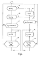
- the microprocessor 53 evaluates this situation via its signal inputs 56 and 57. He can according to the flowchart of FIG. 4 control the anti-trap 49.
- the program goes back to the beginning and goes through the checks cyclically. If, in the course of operation, the tension bar arrangement 25 starts against a resistance, the voltage drop across the sensor resistance 46 rises above the limit value 1. Thus, the query block 64 is exited to a following instruction block 65. Here, the power for the relay 48 is turned on, whereby the normally closed contact 47 is opened and the current through the motor 37 is interrupted.
- the microprocessor 53 checks whether the voltage on the line 51 has become equal to the voltage on the line 52, indicating that the user has shut down the window blind, or if the voltages on the lines 51 and 52 have previously been reversed, which means that the user wants to operate the blind in the sense of a retraction. If either condition is met, the program returns to the beginning, otherwise to the beginning of the instruction block 65. Thus, power to the motor 37 is forcibly turned off via the electrical pinch guard 45 until the user arbitrarily turns off the window blind, or in the sense of opening.
- the anti-pinch circuit shown is not only suitable for side window blinds, as they are explained with reference to FIGS. 1 and 2, but also for roof window blinds, as shown in Fig. 5, or for rear window blinds, as far as the operation of the tension rod assembly 25 as shown in FIG Fig. 2 takes place.
- the tension rod assembly 25 with the over the roller blind 19 laterally projecting guide arms 26 dives through the slot in the parcel shelf.
- the slot edges can act as a pair of scissors together with the laterally over the roller blind 19 projecting guide arms 26.
- An inevitable shutdown of the motor current in both directions of movement is therefore advisable.
- the gear motor When extended, the gear motor must operate against the action of the spring motor 42 and also overcome the frictional resistance of the thrust members 32 in the guide tubes or guide rails 29. When retracting, the conditions are reversed in that the spring motor 42 has a supporting effect.
- FIG. 4 the basic flowchart of FIG. 4 is expanded by a query block 67, in which it is checked whether the motor 37 receives a larger current in the reverse direction than is permissible according to a limit value II. If yes, an instruction block 68 is approached, which leads to the opening of the normally closed contact 47. This instruction block 68 is again executed until either the direction of rotation is reversed or the motor is switched off, which is checked in an instruction block 69.
- the monitoring of the instantaneous value of the motor current is provided.
- the instantaneous value of the motor current corresponds to the torque delivered by the motor.
- the current change dI / dt ie the derivative of the motor current after the time can be used.
- the program according to FIG. 4 thus remains unchanged, with the proviso that instead of the instantaneous value U 46, the differential of the voltage dU 46 / dt is used.
- the differentiating circuit can also be realized in software in the microprocessor 53.
- the electric motor 37 contains one or more Hall probes 70, as indicated by dashed lines in FIG. 3 by way of example.
- the flowchart of Fig. 3 changes to the effect that in place of U 46, the rotational speed n occurs.
- Fig. 5 shows a schematic view and a similar viewing angle of a section of a vehicle with a slightly different body shape, for the corresponding parts the same reference numerals as in Fig. 1 are used.
- the roof 2 includes a rectangular roof opening 71 by a corresponding roof window is housed.
- a roller blind 21 Below the roof cutout 71 is a roller blind 21, the free edge of a Extensible profile 72 is attached, which corresponds to the tension rod assembly 25 of FIG.
- the operation of the pull-out profile 72 is done via a similar mechanism as shown in Fig. 2.
- the winding shaft is located in the region of the vehicle rear edge of the roof cutout 71 while the guide rails 29 extend parallel to the side edges.
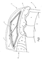
- Fig. 6 shows a rear window roller blind, in which the actuation of the roller blind is effected via two one-armed lever 75.
- the already mentioned winding shaft 22 is rotatably mounted in an elongated tubular housing 76. It is, as in the previous embodiments, biased by means of a spring motor in the sense of winding the blind sheet 21.
- a pull-out profile 77 At the free edge of the roller blind 21, i. the edge remote from the winding shaft is a pull-out profile 77, the function of the Switzerlandstaban extract 25 largely corresponds. It contains on the side facing the viewer grooves 78 which extend over the entire length of the extract profile. In these grooves slide the free ends of the two levers 75th
- the levers 75 are rotatably mounted on an output shaft 79 at its lower end.
- the output shaft 79 is part of an angular gear which is housed in a housing 81 and 82, respectively.
- the housings 81 and 82 are spaced apart from and fixed to the housing 76 as shown in the longitudinal direction.
- the output shafts 79 are parallel to each other.
- the arrangement is driven by the DC motor 37, for example, optionally displacing a worm contained in the gear housing 82 in revolutions. Via a coupling shaft 83, the motor 37 is also connected to the transmission contained in the transmission housing 81.
- Fig. 6 shows the rear window blind in the extended position.
- the levers 75 are in this position approximately at right angles to the longitudinal extent of the roller shaft 22.
- To retract the geared motor 37 is rotated with the corresponding direction in turns. This causes the two levers 75 to pivot towards each other, as a result of which the distance their free ends from the roller shaft 22 has decreases correspondingly.
- the coupled with the roller shaft 22 spring motor ensures that the roller blind 21 remains tensioned in any position of the lever 75.
- the retraction position is reached when the two levers 75 extend approximately parallel to the winding shaft 22.
- the blind housing 76 is located below the parcel shelf 14, as shown in Fig. 1.
- the roller blind moves through actuation by a slot contained in the rear shelf 14.
- the levers 75 are approximately parallel to the inside of the rear window 4.
Abstract
Description
In zunehmendem Maße werden in Pkw's elektrisch betätigte Sonnenrollos verwendet. Diese Sonnenrollos kommen an den Seitenfenstern der hinteren Türen, der Heckscheibe oder dem Glasdach zur Anwendung. Ein Fensterrollo für Heckscheiben ist beispielsweise aus der
Der Antrieb des Spriegels geschieht über linienförmige Schubglieder die in den Führungsschienen laufen. Die Antriebsglieder ihrerseits sind formschlüssig über ein Ausgangszahnrad eines Getriebemotors angetrieben.The drive of the bow is done via linear thrust members running in the guide rails. The drive links in turn, are positively driven by an output gear of a geared motor.
Grundsätzlich den gleichen Aufbau zeigen die Rollos von Kraftfahrzeugseitenfenstern oder auch die Rollos von Dachfenstern. Wegen des elektromotorischen Antriebs besteht eine gewisse Einklemmgefahr. Der Motor ist hinsichtlich der zur Verfügung stehenden Antriebskraft einigermaßen überdimensioniert. Das Abschalten des Motors ist in aller Regel zeitgesteuert, was bedeutet, dass beim Ausfahren des Rollos der Spriegel gegen einen formschlüssigen Anschlag läuft und dort mit hoher Kraft angepresst bleibt solange, bis durch das Zeitgitter der Motor abgeschaltet wird.Basically the same structure show the blinds of motor vehicle side windows or the blinds of skylights. Because of the electric motor drive there is a certain risk of trapping. The engine is reasonably oversized in terms of the available drive power. The shutdown of the engine is usually time-controlled, which means that when extending the blinds of the bow against a positive stop runs and there pressed with high force remains until the engine is shut off by the time grid.
Die Betätigungskraft ist verhältnismäßig hoch und es besteht durchaus eine gewisse Verletzungsgefahr, wenn jemand mit Körperteilen zwischen dem sich bewegenden Spriegel und einem festen Anschlag im Fahrzeug gelangt. Die Gefahr besteht sowohl beim Einfahren als auch beim Ausfahren. Die Gefahr ist insbesondere bei Seitenfenstern verhältnismäßig groß, wenn die Seitenscheibe heruntergelassen ist. Ähnliche Verhältnisse liegen vor bei einem geöffneten Glasdach.The actuation force is relatively high and there is a certain risk of injury if someone gets with body parts between the moving bow and a firm stop in the vehicle. The danger exists both during retraction and during extension. The danger is particularly large in side windows when the side window is lowered. Similar conditions exist with an open glass roof.
Bei Heckfenstern, bei denen der Spriegel bzw. das Auszugsprofil über eine Hebelanordnung betätigt wird, entsteht auch eine gewisse Gefahr des Einklemmens, wenn das Rollo einfährt, weil hier das Auszugsprofil nicht passiv über den Federmotor der Wickelwelle sondern über den Elektromotor erfolgt.In rear windows, in which the bow or the pull-out profile is actuated via a lever arrangement, there is also a certain risk of pinching when the roller blind enters because here the pull-out profile is not passive via the spring motor of the winding shaft but via the electric motor.
Ausgehend hiervon ist es Aufgabe der Erfindung ein Rollo zu schaffen, bei dem die Verletzungsgefahr durch Einklemmen vermindert ist.Based on this, it is an object of the invention to provide a roller blind in which the risk of injury is reduced by trapping.
Diese Aufgabe wird erfindungsgemäß durch ein Fensterrollo mit den Merkmalen des Anspruches 1 gelöst.This object is achieved by a window blind with the features of
Bei dem neuen Fensterrollo ist eine Wickelwelle vorgesehen, die drehbar gelagert ist. An der Wickelwelle ist eine Rollobahn mit einer Kante befestigt. Die von der Wickelwelle abliegende Kante ist mit einer Zugstabanordnung verbunden.In the new window blind a winding shaft is provided, which is rotatably mounted. At the winding shaft a roller blind is attached with an edge. The edge remote from the winding shaft is connected to a tension rod arrangement.
Es ist wenigstens ein Elektromotor vorgesehen, um die Rollobahn in wenigstens einer Richtung zu bewegen. Dem Elektromotor ist ein Sensor zugeordnet, um einen Betriebsparameter des Elektromotors zu erfassen. Dieser Betriebsparameter kann je nach Einbauort und Zweckmäßigkeit der Gesamtanordnung der vom Motor aufgenommene Strom, die Stromänderung dI/dt des Motorstroms oder die Drehzahl des Motors oder die Drehzahländerung dn/dt sein. Diese Betriebsparameter ändern sich abhängig davon, ob der Motor lediglich die Rollobahn bewegt, oder ob zusätzlich irgendwelche Gegenstände sich im Bewegungsweg des Auszugsprofils befinden und eine Blockierung hervorrufen würden. Hierdurch kann sicher ein Einklemmen mit Verletzungsgefahr vermieden werden. Gleichzeitig ermöglicht diese Anordnung eine Endabschaltung mit geringer Verspannung im System.At least one electric motor is provided in order to move the roller blind in at least one direction. The electric motor is associated with a sensor to detect an operating parameter of the electric motor. This operating parameter may be dn / dt depending on the location and convenience of the overall arrangement of the current consumed by the motor, the current change dI / dt of the motor current or the speed of the motor or the speed change. These operating parameters change depending on whether the motor is merely moving the roller blind, or whether any objects are additionally in the path of movement of the pull-out profile and would cause a blockage. As a result, a trapping with risk of injury can be safely avoided. At the same time, this arrangement enables a low-voltage end shutdown in the system.
Eine mit dem Sensor verbundene Steuerschaltung wertet das vom Sensor abgegebene Signal aus und sorgt dafür, dass unabhängig von der sonstigen Betätigung der Motorstrom zwangsläufig abgeschaltet wird, wenn der Grenzwert überschritten wird.A control circuit connected to the sensor evaluates the signal emitted by the sensor and ensures that, independently of the other operation, the motor current is forcibly switched off when the limit value is exceeded.
Durch diese Maßnahme kann die Kraft, die an der Zugstabanordnung entsteht in solchen Grenzen gehalten werden, dass eine Verletzung praktisch ausgeschlossen ist.By this measure, the force that arises at the tension rod assembly can be kept within such limits, that an injury is practically excluded.
Je nachdem wie das Rollo mechanisch ausgeführt ist, d.h. ob die Zugstabanordnung im Sinne des Wegbewegens von dem Auszugsschlitz mit dem Elektromotor betätigt wird oder in der entgegengesetzten Richtung, kann der Grenzwert dem Betriebsparameter beim Ausfahren oder dem Betriebsparameter beim Einfahren zugeordnet werden.Depending on how the blind is made mechanically, i. E. Whether the tension rod assembly is actuated in the direction of moving away from the pullout slot with the electric motor or in the opposite direction, the limit value can be assigned to the operating parameter during extension or the operating parameter during retraction.
Wenn die Bewegung der Zugstabanordnung in beiden Richtungen durch den Elektromotor erfolgt und in beiden Richtungen eine Einklemmgefahr besteht, kann es von Bedeutung sein bei beiden Bewegungsrichtungen die Überwachung des Betriebsparameters vorzunehmen.If the movement of the tension rod arrangement takes place in both directions by the electric motor and there is a danger of pinching in both directions, it may be important to monitor the operating parameter in both directions of movement.
Bei heute weit verbreiteten Heckscheibenrollos verfolgt das Aufwickeln der Rollobahn auf die Wickelwelle unter Zuhilfenahme eines Federmotors. In diesem Falle genügt es, wenn lediglich der Strom beim Ausfahren überwacht wird.In today widespread rear window blinds, the winding of the roller blind track on the winding shaft pursues with the aid of a spring motor. In this case, it is sufficient if only the power is monitored during extension.
Im Übrigen sind Weiterbildungen Gegenstand von Unteransprüchen.For the rest, further developments are the subject of dependent claims.
In der nachfolgenden Figurenbeschreibung sind einige prinzipielle Ausführungsbeispiele erläutert, ohne dass auf das letzte Detail eingegangen wird. Es versteht sich, dass diese grundsätzlichen Ausführungsformen abwandelbar sind, um sie an die jeweilige Anwendungssituation anzupassen.In the following description of the figures, some basic embodiments are explained, without going into the last detail. It is understood that these basic embodiments can be modified in order to adapt them to the respective application situation.
In der Zeichnung sind Ausführungsbeispiele des Gegenstandes der Erfindung dargestellt. Es zeigen:
- Fig. 1
- den aufgebrochenen Fondbereich eines Pkw mit Blick auf die rechte hintere Innenseite, in einer schematisierten perspektivischen Darstellung;
- Fig. 2
- den prinzipiellen mechanischen Aufbau des Seitenfensterrollos, wie es in dem Fahrzeug nach Fig. 1 eingebaut ist;
- Fig. 3
- das Prinzipschaltbild zur Motorstromüberwachung;
- Fig. 4
- das Flussdiagramm zu der Motorstromüberwachung nach Fig. 3;
- Fig. 5
- eine Darstellung des Dachbereiches eines PKWs mit einem Dachfensterrollo und
- Fig. 6
- ein Heckfensterrollo in einer perspektivischen Darstellung mit einer Hebelanordnung zum Bewegen der Zugstabanordnung.
- Fig. 1
- the broken rear area of a car with View of the right rear inside, in a schematic perspective view;
- Fig. 2
- the basic mechanical structure of the side window roller blind, as it is installed in the vehicle of Figure 1;
- Fig. 3
- the block diagram for motor current monitoring;
- Fig. 4
- the flowchart to the motor current monitoring of Fig. 3;
- Fig. 5
- a representation of the roof area of a car with a roof window roller blind and
- Fig. 6
- a rear window blind in a perspective view with a lever arrangement for moving the tension rod assembly.
Fig. 1 stellt den aufgebrochenen abgeschnittenen Fondbereich eines Pkw dar. Die Figur veranschaulicht einen Blick auf die rechte Innenseite, die zu der nicht veranschaulichten linken Innenseite spiegelbildlich ist. Die Darstellung ist vereinfacht. So sind beispielsweise Karosserinnenstrukturen, wie Versteifung und Befestigungsmittel nicht gezeigt, da ihre Darstellung für das Verständnis der Erfindung nicht erforderlich ist. Ebenso ist die Darstellung der Karosserie schematisiert und lässt die dort vorhandenen Hohlräume nicht erkennen.Fig. 1 illustrates the broken-off cut rear region of a passenger car. The figure illustrates a view of the right inner side, which is a mirror image of the unillustrated left inner side. The presentation is simplified. For example, body structures, such as stiffening and fastening means are not shown because their representation is not required for the understanding of the invention. Similarly, the representation of the body is schematic and does not recognize the existing cavities there.
Der veranschaulichte Karosserieabschnitt 1 weist ein Dach 2 auf, von dem seitlich eine B-Säule 3 nach unten zu einer nicht gezeigten Bodengruppe führt. Die entsprechende B-Säule wäre auf der weggebrochenen Seite des Fahrzeugs zu denken. Die B-Säulen sind geneigt, so dass ihr oberes Ende zum Fahrzeugheck verlagert ist.The illustrated
Das Dach 2 geht an seiner Hinterkante in ein Heckfenster über. Seitlich endet das Heckfenster an einer C-Säule 5, die sich im Abstand zu der B-Säule 3 befindet. Die C-Säule 5 trägt eine Innenverkleidung 6.The
Zwischen der B-Säule 3 und der C-Säule 6 ist an der B-Säule eine hintere rechte Seitentür 7 in bekannter Weise anscharniert.Between the
Auf der Höhe der hinteren rechten Seitentür 7 befindet sich eine Rücksitzbank 8, zu der eine Sitzfläche 9 sowie eine Rücksitzlehne 11 gehören. Die Rücksitzfläche 9 liegt auf einer Sockelfläche 12, die zu einer Bodengruppe gehört und vor der Fußräume 13 ausgebildet sind.At the height of the rear
Auf der Höhe der Oberkante der Rücksitzlehne 11 erstreckt sich eine Hutablage 15 zu der Unterkante der Heckscheibe 4.At the height of the upper edge of the rear seat back 11, a
Die hintere rechte Seitentür 7 ist in der für Limousinen üblichen Weise mit einem Seitenfenster 15 versehen. Das Seitenfenster 15 wird durch eine etwa vertikal verlaufende Strebe 16 in ein im Wesentlichen viereckiges Fensterfeld 17 sowie ein etwa dreieckiges Fensterfeld 18 aufgeteilt. Am unteren Ende werden die beiden Felder 17 und 18 von einer Fensterbrüstung 19 begrenzt. Die Fensterbrüstung 19 verläuft unter einem Winkel kleiner als 90° zu einer vorderen Fensterkante 20.The rear
Die in dem Fensterfeld 17 vorhandene Scheibe ist in bekannter Weise auf und ab zu bewegen, wozu sie unter anderem in der vertikalen Strebe 16 in bekannter Weise geführt ist.The present in the
Das Fensterfeld 17 ist durch eine zugeordnete Rollobahn 21 wahlweise abzuschatten, die durch einen Schlitz in der Fensterbrüstung 19 aus dem Innenraum der Tür 7 ausziehbar ist. Der Antriebsmechanismus für die Rollobahn 21 befindet sich in dem Innenraum der Tür 7 unterhalb der Fensterbrüstung 19.The
Fig. 2 zeigt die wesentlichen Bestandteile, die dazu vorgesehen sind, die Rollobahn 21 anzutreiben, zu führen bzw. im nicht gebrauchten Zustand aufzubewahren.Fig. 2 shows the essential components which are intended to drive the
Die Rollobahn 21 weist einen Zuschnitt auf, der etwa der Fläche des Fensterfeldes 17 entspricht und durch im Wesentlichen gerade Kanten angenähert ist. Die Rollobahn 21 ist mit ihrer Unterkante an einer Wickelwelle 22 befestigt, die zwischen Wickelwellenlageranordnungen 23 und 24 drehbar und axial beweglich gelagert ist.The
Die von der Wickelwelle 22 abliegende Kante der Rollobahn 21 bildet eine schlauchförmige Schlaufe, durch die hindurch eine biegefeste Zugstabanordnung 25 hindurch führt. Von der Zugstabanordnung 25 sind lediglich deren außen liegende Führungsarme 26 zu erkennen. Der Führungsarm 26 trägt endseitig einen Führungskörper 28. Beide Führungsarme sind in einem starren Mittelstück teleskopartig verschiebbar.The edge of the
Um die Rollobahn 21 während einer Ausfahrbewegung zu führen, verlaufen seitlich neben der ausgezogenen Rollobahn 21 zwei Führungsschienen 29. Jede Führungsschiene 29 enthält eine in Längsrichtung durchlaufende Nutenkammer 30, die sich über einen Nutenschlitz 31 in Richtung auf die Rollobahn 21 öffnet und im Querschnitt kreisförmig ist.To the
In den beiden Nutenkammern 30 der beiden Führungsschienen 29 laufen axial beweglich zugehörige und schraubenförmig verzahnte Schubglieder 32. Jedes Schubglied 32 besteht aus einer zylindrischen Seele 33, um die herum schraubenförmig eine erhabene Wendel 34 umläuft. Die Wendel 34 bildet einen schraubenförmig um die Seele 33 herumlaufenden Zahn. Das Schubglied 32 hat somit die Gestalt einer schräg verzahnten flexiblen Zahnstange mit kreisförmigem Querschnitt.In the two
Die Schubglieder (32) sind mit ihrem oberen Ende zug-und druckfest mit dem zugehörigen Führungskörper 28 verbunden.The thrust members (32) are connected with its upper end tension and pressure resistant with the associated
Die Schubglieder 32 sind an sich nur sehr wenig knicksteif, weshalb sie in der Nutenkammer 30 ausknicksicher geführt sind.The
Am unteren Ende jeder Führungsschiene 29 schließt sich ein Führungsrohr 35 an, das die Nutenkammer 30 der betreffenden Führungsschiene 29 mit einem Getriebemotor 36 verbindet.At the lower end of each
Zu dem Getriebemotor 36 gehört ein permanent erregter Gleichstrommotor 37, der ein Getriebe antreibt, das sich in einem Getriebegehäuse 38 befindet. Auf einer Ausgangswelle 39 sitzt ein Ausgangszahnrad 40, das so gestaltet ist, dass es formschlüssig in die Verzahnung der beiden Schubglieder 32 eingreifen kann. Damit die Schubglieder 32 seitlich nicht ausweichen können, sind sie in Bohrungen 41 geführt, die tangential an dem Ausgangszahnrad 40 vorbei laufen. An diese Bohrungen 41 schließen die Führungsrohre 35 an.To the
In Verlängerung der Bohrungen 41 können noch Speicherrohre vorhanden sein, um den nicht aktiven Teil des Schubglieds geordnet zu führen.In extension of the
Die Wirkungsweise der erläuterten Anordnung ist wie folgt:The operation of the illustrated arrangement is as follows:
Im eingefahren Zustand liegt die Schlaufe unmittelbar benachbart zu der Wickelwelle 22, d.h. sie ist unterhalb der Brüstung 19 des Seitenfensters 17 zurückgezogen. Wenn der Benutzer, ausgehend von dieser Stellung die Rollobahn 21 vor dem Fenster 17 aufspannen will, setzt er den Getriebemotor 36 in Gang. Hierdurch werden synchron die beiden Schubglieder 32 in die zugehörigen Führungsschienen 29 vorgeschoben. Dabei drücken sie an beiden Seiten der Rollobahn 21 die Führungskörper 28 nach oben, d.h. sie schieben diese vor sich her. Gegen diese Vorschubbewegung wird ein Federmotor 42, wie er in Fig. 2 schematisch angedeutet ist. Die Kraft des Federmotors 42 ist ständig bestrebt, die Rollobahn 21 auf die Wickelwelle 22 auf zu wickeln d.h. zurückzuziehen bzw. festzuhalten.When retracted, the loop is immediately adjacent the winding
Zum Einfahren der Rollobahn 21 wird der Getriebemotor 37 mit der umgekehrten Drehrichtung in Gang gesetzt. Hierdurch werden die Schubglieder 32 aus den Führungsschienen 29 nach unten in Richtung auf die Wickelwelle 22 zurückgezogen und nehmen dabei die angekuppelte Zugstabanordnung 25 nach unten mit. Der in der Wickelwelle 22 enthaltene Federmotor 42 wickelt entsprechend die Rollobahn 21 auf der Wickelwelle 22 auf.For retracting the
Das Einfahren ist beendet, wenn die Schlaufe mit der Zugstabanordnung 25 am Schlitz angekommen ist.The retraction is completed when the loop with the
Wie in den Figuren unschwer zu entnehmen ist, besteht eine gewisse Einklemmgefahr beim Ausfahren des Seitenfensterrollos. Wenn nämlich beispielsweise die Seitenscheibe geöffnet ist und der Getriebemotor im Sinne eines Ausfahrens der Rollobahn 21 in Gang gesetzt wird, kann zwischen der biegesteifen Zugstabanordnung 25 und der Fensteroberkante etwas eingeklemmt werden. Die von dem Getriebemotor 36 gelieferte Kraft kann durchaus so hoch sein, dass Verletzungen beim Einklemmen zwischen der Fensteroberkante und der Zugstabanordnung 25 nicht immer ausgeschlossen sind.As can be easily seen in the figures, there is a certain risk of entrapment when extending the side window roller blind. For example, if the side window is open and the geared motor is set in motion in the sense of extending the
Um dem vorzubeugen ist eine in Fig. 3 schematisch dargestellter elektrischer Einklemmschutz 45 vorgesehen. Der Einklemmschutz weist einen elektrisch mit dem Gleichstrommotor 37 in Serie liegenden Stromsensorwiderstand 46 auf, der mit einem Ruhekontakt 47 eines Relais 48 verbunden ist. In dem Ruhekontakt 47 besteht eine elektrische Verbindung zu einem Bordnetz 49 über eine Verbindungsleitung 50. Eine weitere Anschlussleitung 52 verbindet das andere Ende des Gleichstrommotors 37 ebenfalls mit dem Bordnetz 49, das hier lediglich schematisch gezeigt ist. In der Praxis wird es sich hierbei um die zentrale Steuerung des Kraftfahrzeugs handeln, mit deren Hilfe über einen Schalter gesteuert ist, normalerweise der Getriebemotor 37 für das Seitenfensterrollo wahlweise in jeweiligen Betriebsrichtung in Gang gesetzt werden kann. Ein Eingehen auf die Anordnung innerhalb des Bordnetzes 49 wird sich an dieser Stelle, da sie nicht Gegenstand der Erfindung ist.To prevent this is shown in Fig. 3 schematically illustrated
Zum Erfassen des von dem Gleichstrommotor 37 aufgenommenen Stroms ist ein Mikroprozessor oder Mikrokontroller 53 vorgesehen, der mit seinen Eingängen 54 und 55 zu dem Stromsensorwiderstand 46 parallel liegt. Ein weiterer Eingang 56 ist an die Anschlussleitung 52 angeschlossen, während ein Eingang 57 des Mikroprozessors zu der Verbindungsleitung 51 führt. Über zwei Ausgänge 58 und 59 ist der Magnetwickler des Relais 48 mit dem Mikroprozessor 53 verbunden.For detecting the current absorbed by the
Solange der Ruhekontakt 47 geschlossen ist, arbeitet die Anordnung in der üblichen Weise. Je nach Drehrichtung des Gleichstrommotors 37 liegt entweder die Leitung 51 auf Masse, während die andere Leitung 52 die volle Batteriespannung führt, oder bei umgekehrter Drehrichtung liegt die Leitung 52 auf Masse, während auf der Leitung 51 die volle Batteriespannung ansteht. Der Gleichstrommotor 37 ist abgeschaltet, wenn entweder beide Leitungen 51 und 52 auf Massepotential liegen oder auf dem Potential der Batteriespannung.As long as the normally closed
Der Mikroprozessor 53 wertet über seine Signaleingänge 56 und 57 diese Situation aus. Er kann gemäß dem Flussdiagramm nach Fig. 4 den Einklemmschutz 49 steuern.The
Wenn gemäß der Überprüfung im Abfragblock 61 die Spannung der Leitung 51 gleich der Spannung auf der Leitung 52 ist, ist der Strom für das Relais 48 abgeschaltet und somit der Ruhekontakt 47 geschlossen (Anweisungsblock 62). Wenn die beiden Spannungen nicht gleich sind, liegt beispielsweise ein Betrieb im Sinne des Ausfahrens des Rollos vor, wenn die Spannung auf der Leitung 52 größer ist als die Spannung auf der Leitung 51, was im Abfrageblock 63 geprüft wird. In diesem Falle setzt die Überwachung im Abfrageblock 64 ein und der Mikroprozessor 53 prüft den Spannungsabfall an den Widerstand 46. So lange diese Spannung unter einem vorbestimmten Wert bleibt, wird geschlossen, dass die Zugstabanordnung 26 nicht gegen einen Widerstand anläuft und damit keine Einklemmgefahr besteht. Das Programm geht wieder an den Anfang zurück und durchläuft die Überprüfungen zyklisch. Sollte im Laufe des Betriebs die Zugstabanordnung 25 gegen einen Widerstand anlaufen, steigt der Spannungsabfall an dem Sensorwiderstand 46 über den Grenzwert 1 an. Damit wird der Abfrageblock 64 zu einem folgenden Anweisungsblock 65 verlassen. Hier wird der Strom für das Relais 48 eingeschaltet, wodurch der Ruhekontakt 47 geöffnet wird und der Strom durch den Motor 37 unterbrochen wird.When, according to the check in the
In einem nachfolgenden Abfrageblock 66 prüft der Mikroprozessor 53, ob die Spannung auf der Leitung 51 gleich der Spannung auf der Leitung 52 geworden ist, was darauf hindeutet, dass der Benutzer das Fensterrollo abgeschaltet hat, oder ob sich die Spannungen an den Leitungen 51 und 52 gegenüber vorher umgekehrt haben, was bedeutet, dass der Benutzer das Rollo im Sinne eines Einfahrens betätigen will. Wenn eine von beiden Bedingungen erfüllt ist, kehrt das Programm an den Anfang zurück, andernfalls an den Anfang des Anweisungsblocks 65. Dadurch bleibt der Strom für den Motor 37 so lange zwangsweise über den elektrischen Einklemmschutz 45 abgeschaltet, bis der Benutzer willkürlich das Fensterrollo abschaltet, oder im Sinne eines Öffnens in Gang setzt.In a
Die gezeigte Einklemmschutzschaltung eignet sich nicht nur für Seitenfensterrollos, wie sie anhand der Fig. 1 und 2 erläutert sind, sondern auch für Dachfensterrollos, wie sie in Fig. 5 gezeigt sind, oder für Heckscheibenrollos, soweit die Betätigung der Zugstabanordnung 25 entsprechend der Darstellung in Fig. 2 erfolgt.The anti-pinch circuit shown is not only suitable for side window blinds, as they are explained with reference to FIGS. 1 and 2, but also for roof window blinds, as shown in Fig. 5, or for rear window blinds, as far as the operation of the
Wenn der in Fig. 2 gezeigte Mechanismus und Grundaufbau eines Rollos für ein Heckfensterrollo verwendet wird, wie es aus dem Stand der Technik ebenfalls bekannt ist, beispielsweise aus der
Umgekehrt kann eine Einklemmgefahr auch beim Einfahren vorliegen. Die Zugstabanordnung 25 mit den über die Rollobahn 19 seitlich überstehenden Führungsarmen 26 taucht durch den Schlitz in der Hutablage durch. Dabei können die Schlitzränder zusammen mit den seitlich über die Rollobahn 19 überstehenden Führungsarme 26 wie eine Schere wirken. Ein zwangsläufiges Abschalten des Motorstroms bei beiden Bewegungsrichtungen ist deswegen angeraten. Allerdings unterscheiden sich je nach Bewegungsrichtung von Haus aus die vom Motor aufzubringenden Kräfte. Beim Ausfahren muss der Getriebemotor gegen die Wirkung des Federmotors 42 arbeiten und außerdem den Reibungswiderstand der Schubglieder 32 in den Führungsrohren bzw. Führungsschienen 29 überwinden. Beim Einfahren kehren sich die Verhältnisse insofern um, als der Federmotor 42 unterstützend wirkt. Außerdem werden die Schubglieder 32 auf Zug belastet und nicht auf Druck und können dabei durchaus andere Reibwerte in den Führungsrohren 42 erzeugen. Schließlich kommt noch hinzu, dass beim Einfahren die Einklemmgefahr im unteren Bewegungsbereich vorliegt, dann nämlich, wenn die Schubglieder 32 weitgehend aus den Führungsschienen 29 zurückgezogen sind und sich die Schubglieder 32 weitgehend kräftefrei in den Speicherrohren befinden. Es macht also Sinn mit zwei unterschiedlichen Grenzwerten je nach Bewegungsrichtung zu arbeiten.Conversely, there may be a risk of entrapment even when entering. The
In diesem Falle erweitert sich das prinzipielle Flussdiagramm nach Fig. 4 durch einen Abfrageblock 67, in dem geprüft wird, ob der Motor 37 bei der umgekehrten Drehrichtung einen größeren Strom aufnimmt, als es gemäß einem Grenzwert II zulässig ist. Wenn ja, wird ein Anweisungsblock 68 angefahren, der zum Öffnen des Ruhekontaktes 47 führt. Dieser Anweisungsblock 68 wird wiederum so lange ausgeführt, bis entweder sich die Drehrichtung umkehrt oder der Motor abgeschaltet wird, was in einem Anweisungsblock 69 überprüft wird.In this case, the basic flowchart of FIG. 4 is expanded by a
In Fig. 3 ist die Überwachung des Momentanwertes des Motorstroms vorgesehen. Der Momentanwert des Motorstroms entspricht dem vom Motor abgegebenen Drehmoment. Anstelle des Momentanwertes des Motorstroms kann auch die Stromänderung dI/dt, also die Ableitung des Motorstroms nach der Zeit verwendet werden. Das Programm gemäß Fig. 4 bleibt damit unverändert, mit der Maßgabe, dass anstelle des Momentanwertes U46 das Differenzial der Spannung dU46/dt verwendet wird. Hierzu genügt es zwischen dem Stromsensor 46 und dem Programm eine Differenzierschaltung vorzusehen. Die Differenzierschaltung kann auch softwaremäßig in dem Mikroprozessor 53 realisiert werden.In Fig. 3, the monitoring of the instantaneous value of the motor current is provided. The instantaneous value of the motor current corresponds to the torque delivered by the motor. Instead of the instantaneous value of the motor current, the current change dI / dt, ie the derivative of the motor current after the time can be used. The program according to FIG. 4 thus remains unchanged, with the proviso that instead of the instantaneous value U 46, the differential of the voltage dU 46 / dt is used. For this purpose, it is sufficient to provide a differentiating circuit between the
Schließlich ist es denkbar, anstatt den Motorstrom zu überwachen als kennzeichnenden Parameter für eine Einklemmsituation die Motordrehzahl herzunehmen. Dazu enthält der Elektromotor 37 eine oder mehrere Hallsonden 70, wie sie in Fig. 3 gestrichelt exemplarisch angedeutet ist. Das Flussdiagramm nach Fig. 3 ändert sich dahingehend, dass an die Stelle von U46 die Drehzahl n tritt.Finally, instead of monitoring the motor current, it is conceivable to take the motor speed as the characteristic parameter for a pinching situation. For this purpose, the
Auch im Falle der Verwendung der Drehzahl besteht die Möglichkeit, anstelle des Momentanwertes die Drehzahländerung dn/dt als Kriterium heranzuziehen.Even if the speed is used, it is possible to use the speed change dn / dt as the criterion instead of the instantaneous value.
Schließlich kann es zweckmäßig sein eine Kombination der oben genannten Überwachungen von Betriebsparametern zu verwenden, also beispielsweise den Strom und die Drehzahländerung oder die Stromänderung und die Drehzahl usw.Finally, it may be appropriate to use a combination of the above monitoring of operating parameters, such as the current and the speed change or the current change and the speed, etc.
Die Einklemmgefahr besteht auch bei Dachfenstern und Dachfensterrollos. Ein solches ist in Fig. 5 vereinfacht dargestellt.The risk of entrapment also exists for skylights and skylights. Such is shown in simplified form in FIG.
Fig. 5 zeigt in einer schematisierten Ansicht und einem ähnlichen Blickwinkel einen Ausschnitt aus einem Fahrzeug mit einer etwas anderen Karosserieform, für die einander entsprechenden Teile sind dieselben Bezugszeichen wie in Fig. 1 verwendet.Fig. 5 shows a schematic view and a similar viewing angle of a section of a vehicle with a slightly different body shape, for the corresponding parts the same reference numerals as in Fig. 1 are used.
Damit erübrigt sich auch eine erneute Beschreibung.Thus, a new description is unnecessary.
Wie zu erkennen ist, enthält das Dach 2 einen rechteckigen Dachausschnitt 71 indem ein entsprechendes Dachfenster untergebracht ist. Unterhalb des Dachausschnitts 71 befindet sich eine Rollobahn 21, deren freie Kante an einem Auszugsprofil 72 angebracht ist, das der Zugstabanordnung 25 aus Fig. 2 entspricht. Die Betätigung des Auszugsprofils 72 geschieht über einen ähnlichen Mechanismus wie er in Fig. 2 dargestellt ist. Die Wickelwelle befindet sich im Bereich der Fahrzeugheck hin gelegenen Kante des Dachausschnitts 71 während die Führungsschienen 29 parallel zu den Seitenkanten verlaufen.As can be seen, the
Hier besteht die Gefahr des Einklemmens. Diese Gefahr wird mit der Anordnung nach den Fig. 3 und 4 weitgehend eliminiert.Here there is a danger of pinching. This risk is largely eliminated with the arrangement of FIGS. 3 and 4.
Fig. 6 zeigt ein Heckfensterrollo, bei dem die Betätigung der Rollobahn über zwei einarmige Hebel 75 erfolgt. In einem länglichen rohrförmigen Gehäuse 76 ist die bereits erwähnte Wickelwelle 22 drehbar gelagert. Sie ist, wie bei den vorherigen Ausführungsbeispielen, mittels eines Federmotors im Sinne eines Aufwickelns der Rollobahn 21 vorgespannt. An der freien Kante der Rollobahn 21, d.h. der von der Wickelwelle abliegenden Kante befindet sich ein Auszugsprofil 77, das funktionsmäßig der Zugstabanordnung 25 weitgehend entspricht. Es enthält auf der dem Betrachter zugekehrten Seite Nuten 78, die sich über die gesamte Länge des Auszugsprofils erstrecken. In diesen Nuten gleiten die freien Enden der beiden Hebel 75.Fig. 6 shows a rear window roller blind, in which the actuation of the roller blind is effected via two one-
Die Hebel 75 sind an ihrem unteren Ende drehfest auf einer Ausgangswelle 79 befestigt. Die Ausgangswelle 79 gehört zu einem Winkelgetriebe, das in einem Gehäuse 81 bzw. 82 untergebracht ist. Die Gehäuse 81 und 82 sind wie gezeigt in Längsrichtung des Gehäuses 76 voneinander beabstandet und an diesem befestigt. Die Ausgangswellen 79 sind zueinander parallel.The
Angetrieben wird die Anordnung durch den Gleichstrommotor 37 der beispielsweise eine in dem Getriebegehäuse 82 enthaltene Schnecke wahlweise in Umdrehungen versetzt. Über eine Kuppelwelle 83 ist der Motor 37 außerdem mit dem in dem Getriebegehäuse 81 enthaltenen Getriebe verbunden.The arrangement is driven by the
Fig. 6 zeigt das Heckfensterrollo in der ausgefahrenen Stellung. Die Hebel 75 liegen in dieser Stellung etwa rechtwinklig zur Längserstreckung der Rollowelle 22. Zum Einfahren wird der Getriebemotor 37 mit der entsprechenden Drehrichtung in Umdrehungen versetzt. Dieser veranlasst, dass die beiden Hebel 75 aufeinander zu schwenken, wodurch der Abstand, den ihre freien Enden von der Rollowelle 22 haben, entsprechend abnimmt. Der mit der Rollowelle 22 gekuppelte Federmotor sorgt dafür, dass die Rollobahn 21 in jeder Stellung der Hebel 75 gespannt bleibt.Fig. 6 shows the rear window blind in the extended position. The
Die Einfahrstellung ist erreicht, wenn die beiden Hebel 75 etwa parallel zu der Wickelwelle 22 verlaufen.The retraction position is reached when the two
In einer praktischen Ausführung befindet sich das Rollogehäuse 76 unterhalb der Hutablage 14, wie sie in Fig. 1 gezeigt ist. Das Rollo fährt durch Betätigung durch einen in der Hutablage 14 enthaltenen Schlitz aus. In der ausgefahrenen Stellung liegen die Hebel 75 etwa parallel zur Innenseite der Heckfensterscheibe 4.In a practical embodiment, the
Es leuchtet auch hier ohne weiteres ein, dass eine Einklemmgefahr besteht, sowohl in der vollständig ausgefahrenen Stellung zwischen der Fensteroberkante bzw. dem Dach einerseits und dem Auszugsprofil 77 andererseits, als auch dann, wenn das Auszugsprofil 77 zum Abdecken des Schlitzes in der Hutablage auf den Schlitzrändern aufstößt.It is also clear here that there is a risk of entrapment, both in the fully extended position between the upper edge of the window or the roof on the one hand and the pull-out
Bei ausgefahrenem Rollo können, weil die Hebel 75 steil stehen, bei einem verhältnismäßig kleinen Motordrehmoment relativ große Einklemmkräfte erzeugt werden. Im eingefahrenen Zustand hingegen sind die Einklemmkräfte kleiner, weil die Hebel liegen. Um dem Rechnung zu tragen, werden die beiden Grenzwerte I und II entsprechend unterschiedlich festgelegt.When the roller shutter is extended, because the
Als Einklemmschutz bei Fensterrollos von Kraftfahrzeugen ist eine Überwachung eines Betriebsparameters des Elektromotors vorgesehen, der das Fensterrollo bewegt. Der Motorstrom wird abgeschaltet, wenn ein Grenzwert überschritten wird. Dies wird als Signal dafür interpretiert, dass eine Einklemm- oder Quetschsituation vorliegt.As an anti-trap in window blinds of motor vehicles monitoring of an operating parameter of the electric motor is provided, which moves the window blind. The motor current is switched off when a limit is exceeded. This is interpreted as a signal that there is a pinching or squeezing situation.
Claims (17)
mit einer Wickelwelle (22), die drehbar gelagert ist,
mit einer Rollobahn (21), die mit einer Kante an der Wickelwelle (22) befestigt ist und die eine von der Wickelwelle (22) abliegende Kante aufweist,
mit einem Zugstabanordnung (25,77), die an der von der Wickelwelle (22) abliegenden Kante befestig ist,
mit wenigstens einem Elektromotor (37) um die Rollobahn (21) in wenigstens einer Richtung zu bewegen,
mit einem Sensor (46,70), der einen Betriebsparameter des Elektromotors (37) erfasst,
mit einer Steuerschaltung (45), die einen an dem Sensor (46) liegenden Eingang (54,55) aufweist und die ein Steuerprogramm enthält, das den Betriebsparameter des Elektromotors (37) überwacht und bei Überschreiten wenigstens eines vorgegebenen Grenzwertes (I,II) den Strom zu dem Elektromotor (37) unterbricht.Roller blind for motor vehicles (1),
with a winding shaft (22), which is rotatably mounted,
with a roller blind web (21) which is fastened with one edge to the winding shaft (22) and which has an edge remote from the winding shaft (22),
with a tension rod arrangement (25, 77) which is fastened to the edge remote from the winding shaft (22),
with at least one electric motor (37) to move the roller blind (21) in at least one direction,
with a sensor (46, 70) which detects an operating parameter of the electric motor (37),
with a control circuit (45) which has an input (54, 55) located at the sensor (46) and which contains a control program which monitors the operating parameter of the electric motor (37) and when at least one predetermined limit value (I, II) is exceeded. the current to the electric motor (37) interrupts.
Applications Claiming Priority (1)
| Application Number | Priority Date | Filing Date | Title |
|---|---|---|---|
| DE102005030962A DE102005030962A1 (en) | 2005-04-21 | 2005-06-30 | Roller blind for motor vehicle with clamping protection has brake that introduces at least part of thrust into guide rail when deceleration force greater than certain value is applied to bar attached to end of blind |
Publications (1)
| Publication Number | Publication Date |
|---|---|
| EP1739275A2 true EP1739275A2 (en) | 2007-01-03 |
Family
ID=37027792
Family Applications (1)
| Application Number | Title | Priority Date | Filing Date |
|---|---|---|---|
| EP06001574A Withdrawn EP1739275A2 (en) | 2005-06-30 | 2006-01-26 | Roller blind with electrical anti-nipping device |
Country Status (5)
| Country | Link |
|---|---|
| US (1) | US20070000624A1 (en) |
| EP (1) | EP1739275A2 (en) |
| JP (1) | JP2007008463A (en) |
| KR (1) | KR20070003618A (en) |
| CN (1) | CN1891969A (en) |
Families Citing this family (7)
| Publication number | Priority date | Publication date | Assignee | Title |
|---|---|---|---|---|
| ITTV20080004A1 (en) * | 2008-01-10 | 2009-07-11 | Nice Spa | DRIVE FOR ROLLER SHUTTERS WITH PROTECTION AGAINST EXCESSIVE WIND |
| JP4811618B2 (en) * | 2009-06-29 | 2011-11-09 | 八千代工業株式会社 | Sunroof device |
| CN102056362B (en) * | 2009-11-04 | 2013-08-28 | 海洋王照明科技股份有限公司 | Control circuit for vehicle-mounted lamp and vehicle-mounted lamp |
| JP5600484B2 (en) * | 2010-06-09 | 2014-10-01 | 芦森工業株式会社 | Shade device |
| KR101323028B1 (en) * | 2011-10-28 | 2013-10-29 | 주식회사 현대케피코 | Methods of controlling anti pinch system and appratuses using the same |
| FR3024176B1 (en) * | 2014-07-25 | 2016-08-05 | Somfy Sas | METHOD FOR CONTROLLING A WINDING ACTUATOR, CONFIGURED WINDING ACTUATOR FOR SUCH A METHOD AND SOLAR CLOSURE OR PROTECTION PLANT COMPRISING SUCH ACTUATOR |
| DE102018116346A1 (en) * | 2018-07-05 | 2020-01-09 | Webasto SE | shading |
Citations (2)
| Publication number | Priority date | Publication date | Assignee | Title |
|---|---|---|---|---|
| DE10057760A1 (en) | 2000-11-22 | 2002-06-06 | Bos Gmbh | Window roller blind with centering device for the tension rod |
| DE10351040B3 (en) | 2003-10-31 | 2005-05-25 | Bos Gmbh & Co. Kg | Window roller blind for motor vehicles and side paneling with integrated guide rail |
Family Cites Families (19)
| Publication number | Priority date | Publication date | Assignee | Title |
|---|---|---|---|---|
| ZA847740B (en) * | 1983-10-12 | 1985-05-29 | Byrne & Davidson Ind Ltd | Obstruction detection means |
| JPS60115784A (en) * | 1983-11-28 | 1985-06-22 | アイシン精機株式会社 | Automatic opening and closing apparatus of opening covering material |
| DE3612165A1 (en) * | 1986-04-11 | 1987-10-22 | Baumeister & Ostler | LEADER-FREE WINDOW ROLLER, IN PARTICULAR FOR MOTOR VEHICLES |
| US4831509A (en) * | 1986-04-16 | 1989-05-16 | Byrne & Davidson Doors (N.S.W.)Pty. Limited | Door operation control apparatus |
| US5585705A (en) * | 1994-05-05 | 1996-12-17 | Leopold Kostal Gmbh & Co. Kg | Process for monitoring movement of closure devices which may be adjusted by motors |
| KR0171240B1 (en) * | 1994-05-17 | 1999-05-01 | 가다오까 마사다까 | Vehicle-mounted motor drive apparatus |
| US5483135A (en) * | 1994-06-06 | 1996-01-09 | Ford Motor Company | Adaptive system and method for controlling vehicle window operation |
| DE4440449C2 (en) * | 1994-11-14 | 1997-06-12 | Elero Antrieb Sonnenschutz | Method and device for controlling the standstill of electric motor-operated shutters or the like |
| DE59610883D1 (en) * | 1995-10-28 | 2004-02-05 | Elero Gmbh | Method for driving awnings or the like operated by an electric motor |
| US5585702A (en) * | 1995-11-03 | 1996-12-17 | Itt Automotive Electrical Systems, Inc. | Auto up window with osbtacle detection system |
| JPH1162380A (en) * | 1997-08-22 | 1999-03-05 | Alps Electric Co Ltd | Inserting detection method of power window device |
| US6051945A (en) * | 1999-01-25 | 2000-04-18 | Honda Giken Kogyo Kabushiki Kaisha | Anti-pinch safety system for vehicle closure device |
| DE19908658A1 (en) * | 1999-02-27 | 2000-08-31 | Bosch Gmbh Robert | Locking device with security function |
| DE10052042A1 (en) * | 2000-10-20 | 2002-05-16 | Bos Gmbh | Drive system for rollable covering devices of motor vehicles |
| DE10057762A1 (en) * | 2000-11-22 | 2002-06-06 | Bos Gmbh | Window roller blind with compensation against warping |
| EP1379925A1 (en) * | 2001-03-15 | 2004-01-14 | Stoneridge Control Devices, Inc. | Electro-mechanical actuator including brushless dc motor for providing pinch protection |
| DE10297186T5 (en) * | 2001-09-13 | 2004-10-28 | Siemens Vdo Automotive Corp., Auburn Hills | Einklemmerkennungssystem |
| US6906487B2 (en) * | 2002-01-21 | 2005-06-14 | International Rectifier Corporation | Anti-pinch window drive circuit |
| JP3907195B2 (en) * | 2003-09-02 | 2007-04-18 | 矢崎総業株式会社 | Power window prevention device |
-
2006
- 2006-01-26 EP EP06001574A patent/EP1739275A2/en not_active Withdrawn
- 2006-04-10 US US11/401,052 patent/US20070000624A1/en not_active Abandoned
- 2006-06-29 KR KR1020060059170A patent/KR20070003618A/en not_active Application Discontinuation
- 2006-06-29 CN CNA2006100996588A patent/CN1891969A/en active Pending
- 2006-06-29 JP JP2006180051A patent/JP2007008463A/en not_active Withdrawn
Patent Citations (2)
| Publication number | Priority date | Publication date | Assignee | Title |
|---|---|---|---|---|
| DE10057760A1 (en) | 2000-11-22 | 2002-06-06 | Bos Gmbh | Window roller blind with centering device for the tension rod |
| DE10351040B3 (en) | 2003-10-31 | 2005-05-25 | Bos Gmbh & Co. Kg | Window roller blind for motor vehicles and side paneling with integrated guide rail |
Also Published As
| Publication number | Publication date |
|---|---|
| JP2007008463A (en) | 2007-01-18 |
| CN1891969A (en) | 2007-01-10 |
| KR20070003618A (en) | 2007-01-05 |
| US20070000624A1 (en) | 2007-01-04 |
Similar Documents
| Publication | Publication Date | Title |
|---|---|---|
| EP1211110B1 (en) | Roller blind with compensation against distortion | |
| EP1666291B1 (en) | Window roller blind with simplified assembly | |
| EP1782979B1 (en) | Gapless roller blind for rear window | |
| EP1468854B1 (en) | Roller blind for side windows | |
| DE10057764B4 (en) | Window blind with variable shading effect | |
| EP1211109B1 (en) | Roller blind with centring device for the traction bar | |
| EP1619057B1 (en) | Roller blind assembly for side window | |
| EP1182066B1 (en) | Vehicle with roller blind in the roof | |
| EP1886853B1 (en) | Window roller blind actuated by the window handle | |
| EP1123825B9 (en) | Roller blind for rear window | |
| EP2039547B1 (en) | Side window blind with intake aid | |
| DE102007063705B4 (en) | Roller blind with perforated belt drive | |
| EP2060421B1 (en) | Shutter arrangement with lower friction in the drive | |
| EP1533158B1 (en) | Side window roller blind system comprising a window contour part | |
| EP1724137B1 (en) | Window roller blind with axially adjustable winding shaft | |
| DE102007012281A1 (en) | Automatically operated side window blind | |
| EP1550570A2 (en) | Divided roller blind for a vehicle window | |
| EP1739275A2 (en) | Roller blind with electrical anti-nipping device | |
| EP1714813A2 (en) | Roller sun screen with anti jamming device | |
| DE10052042A1 (en) | Drive system for rollable covering devices of motor vehicles | |
| EP1738942A2 (en) | Motor vehicle window blind with a stop rigidly fixed to the drive linkage | |
| DE102005030962A1 (en) | Roller blind for motor vehicle with clamping protection has brake that introduces at least part of thrust into guide rail when deceleration force greater than certain value is applied to bar attached to end of blind | |
| DE202005020693U1 (en) | Roller e.g. side window roller, for motor vehicle, has control switch with control program, which controls operating parameter of electric motor and interrupts current to electric motor when exceeding predetermined limited value | |
| DE102007004665B4 (en) | Window roller blind with drive via the window regulator motor | |
| DE202007015602U1 (en) | Electric side window blind |
Legal Events
| Date | Code | Title | Description |
|---|---|---|---|
| PUAI | Public reference made under article 153(3) epc to a published international application that has entered the european phase |
Free format text: ORIGINAL CODE: 0009012 |
|
| AK | Designated contracting states |
Kind code of ref document: A2 Designated state(s): AT BE BG CH CY CZ DE DK EE ES FI FR GB GR HU IE IS IT LI LT LU LV MC NL PL PT RO SE SI SK TR |
|
| AX | Request for extension of the european patent |
Extension state: AL BA HR MK YU |
|
| STAA | Information on the status of an ep patent application or granted ep patent |
Free format text: STATUS: THE APPLICATION IS DEEMED TO BE WITHDRAWN |
|
| 18D | Application deemed to be withdrawn |
Effective date: 20100202 |