EP2060312A2 - Fluidic device and method for separation of neutrally buoyant particles - Google Patents
Fluidic device and method for separation of neutrally buoyant particles Download PDFInfo
- Publication number
- EP2060312A2 EP2060312A2 EP08168573A EP08168573A EP2060312A2 EP 2060312 A2 EP2060312 A2 EP 2060312A2 EP 08168573 A EP08168573 A EP 08168573A EP 08168573 A EP08168573 A EP 08168573A EP 2060312 A2 EP2060312 A2 EP 2060312A2
- Authority
- EP
- European Patent Office
- Prior art keywords
- fluid
- channel
- spiral
- outlet
- spiral channel
- Prior art date
- Legal status (The legal status is an assumption and is not a legal conclusion. Google has not performed a legal analysis and makes no representation as to the accuracy of the status listed.)
- Granted
Links
Images



Classifications
-
- B—PERFORMING OPERATIONS; TRANSPORTING
- B01—PHYSICAL OR CHEMICAL PROCESSES OR APPARATUS IN GENERAL
- B01D—SEPARATION
- B01D21/00—Separation of suspended solid particles from liquids by sedimentation
- B01D21/26—Separation of sediment aided by centrifugal force or centripetal force
- B01D21/265—Separation of sediment aided by centrifugal force or centripetal force by using a vortex inducer or vortex guide, e.g. coil
-
- B—PERFORMING OPERATIONS; TRANSPORTING
- B01—PHYSICAL OR CHEMICAL PROCESSES OR APPARATUS IN GENERAL
- B01L—CHEMICAL OR PHYSICAL LABORATORY APPARATUS FOR GENERAL USE
- B01L3/00—Containers or dishes for laboratory use, e.g. laboratory glassware; Droppers
- B01L3/50—Containers for the purpose of retaining a material to be analysed, e.g. test tubes
- B01L3/502—Containers for the purpose of retaining a material to be analysed, e.g. test tubes with fluid transport, e.g. in multi-compartment structures
- B01L3/5027—Containers for the purpose of retaining a material to be analysed, e.g. test tubes with fluid transport, e.g. in multi-compartment structures by integrated microfluidic structures, i.e. dimensions of channels and chambers are such that surface tension forces are important, e.g. lab-on-a-chip
- B01L3/502761—Containers for the purpose of retaining a material to be analysed, e.g. test tubes with fluid transport, e.g. in multi-compartment structures by integrated microfluidic structures, i.e. dimensions of channels and chambers are such that surface tension forces are important, e.g. lab-on-a-chip specially adapted for handling suspended solids or molecules independently from the bulk fluid flow, e.g. for trapping or sorting beads or physically stretching molecules
-
- B—PERFORMING OPERATIONS; TRANSPORTING
- B01—PHYSICAL OR CHEMICAL PROCESSES OR APPARATUS IN GENERAL
- B01L—CHEMICAL OR PHYSICAL LABORATORY APPARATUS FOR GENERAL USE
- B01L3/00—Containers or dishes for laboratory use, e.g. laboratory glassware; Droppers
- B01L3/50—Containers for the purpose of retaining a material to be analysed, e.g. test tubes
- B01L3/502—Containers for the purpose of retaining a material to be analysed, e.g. test tubes with fluid transport, e.g. in multi-compartment structures
- B01L3/5027—Containers for the purpose of retaining a material to be analysed, e.g. test tubes with fluid transport, e.g. in multi-compartment structures by integrated microfluidic structures, i.e. dimensions of channels and chambers are such that surface tension forces are important, e.g. lab-on-a-chip
- B01L3/502769—Containers for the purpose of retaining a material to be analysed, e.g. test tubes with fluid transport, e.g. in multi-compartment structures by integrated microfluidic structures, i.e. dimensions of channels and chambers are such that surface tension forces are important, e.g. lab-on-a-chip characterised by multiphase flow arrangements
- B01L3/502776—Containers for the purpose of retaining a material to be analysed, e.g. test tubes with fluid transport, e.g. in multi-compartment structures by integrated microfluidic structures, i.e. dimensions of channels and chambers are such that surface tension forces are important, e.g. lab-on-a-chip characterised by multiphase flow arrangements specially adapted for focusing or laminating flows
-
- B—PERFORMING OPERATIONS; TRANSPORTING
- B03—SEPARATION OF SOLID MATERIALS USING LIQUIDS OR USING PNEUMATIC TABLES OR JIGS; MAGNETIC OR ELECTROSTATIC SEPARATION OF SOLID MATERIALS FROM SOLID MATERIALS OR FLUIDS; SEPARATION BY HIGH-VOLTAGE ELECTRIC FIELDS
- B03B—SEPARATING SOLID MATERIALS USING LIQUIDS OR USING PNEUMATIC TABLES OR JIGS
- B03B5/00—Washing granular, powdered or lumpy materials; Wet separating
- B03B5/62—Washing granular, powdered or lumpy materials; Wet separating by hydraulic classifiers, e.g. of launder, tank, spiral or helical chute concentrator type
- B03B5/626—Helical separators
-
- B—PERFORMING OPERATIONS; TRANSPORTING
- B01—PHYSICAL OR CHEMICAL PROCESSES OR APPARATUS IN GENERAL
- B01D—SEPARATION
- B01D2221/00—Applications of separation devices
- B01D2221/10—Separation devices for use in medical, pharmaceutical or laboratory applications, e.g. separating amalgam from dental treatment residues
Definitions
- Conventional municipal water treatment (MWT) and other types of water purification systems include multi-stage filtration and sequential process steps for coagulation, flocculation, and sedimentation.
- a minimum of two stages of filtration typically include coarse 2-3 mm mesh filters at the inlet and 20-40 ⁇ m multi-media filters for finishing, although many utilities have more intermediate filtration steps.
- Neutrally buoyant particles e.g. particles having substantially the same density as water
- TOC total organic carbon
- the system comprises an inlet to receive at least a portion of the fluid containing the neutrally buoyant particles, a spiral channel within which the fluid flows in a manner such that the neutrally buoyant particles flow in a tubular band offset from a center of the channel, a first outlet for the fluid within which the tubular band flows, and, a second outlet for the remaining fluid or effluent.
- the inlet is angled to facilitate earlier formation of the tubular band along an inner wall of the spiral channel using a Coanda effect where wall friction helps to attach impinging flow.
- system further comprises a second spiral channel nested with the spiral channel such that the tubular band is narrowed as a result of flowing through the second spiral channel.
- the system further comprises a second inlet connected to the second outlet of the spiral channel to receive the remaining fluid, a second spiral channel within which the remaining fluid flows such that the remaining neutrally buoyant particles flow in a second tubular band offset from the center of the second channel, a third outlet for the fluid within which the second tubular band flows, and, a fourth outlet for more remaining fluid.
- the remaining neutrally buoyant particles are of a different size than the neutrally buoyant particles output through the first outlet.
- system further comprises a second spiral channel within which at least another portion of the fluid flows.
- system further comprises a recirculation channel between the first outlet and the inlet.
- the tubular band is formed as a function of at least one of fluid viscosity, average channel velocity, particle radius, fluid density, hydraulic diameter of channel, angular velocity, and differential velocity across particles.
- the tubular band is offset from the center of the channel as a function of a radius of curvature of the spiral channel.
- the spiral channel is a spiral wound structure.
- the spiral channel is a helical spiral structure.
- the method comprises receiving at least a portion of the fluid containing the neutrally buoyant particles at an inlet, establishing a flow of the fluid in a spiral channel wherein the neutrally buoyant particles flow in a tubular band through the spiral channel in an asymmetric manner, outputting the fluid within which the tubular band flows through a first outlet of the channel, and, outputting the remaining fluid through a second outlet of the spiral channel.
- the fluid is received at an angle to facilitate the formation of the tubular band along an inner wall of the spiral channel.
- the method further comprises establishing a second flow of the fluid through a second spiral channel nested with the spiral channel to narrow the tubular band.
- the method further comprises establishing a flow of the remaining fluid in a second spiral channel cascaded with the first spiral channel to separate neutrally buoyant particles of a different size than the neutrally buoyant particles output through the first outlet.
- the method further comprises establishing a flow of at least another portion of fluid in a second spiral channel.
- the method further comprises re-circulating in the system at least a portion of the fluid output through the first outlet.
- the flow of neutrally buoyant particles in a tubular band is adjustable as a function of fluid viscosity, average channel velocity, particle radius, fluid density, hydraulic diameter of the channel, angular velocity, and differential velocity across particles.
- the asymmetric manner of flow of the tubular band is a function of a radius of curvature of the spiral channel.
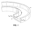
- FIGURE 1 is a representation of a particle flowing through a channel and forces acting thereon;
- FIGURES 2(a) and (b) illustrate a selected quantification of particle extraction
- FIGURES 3(a)-(f) illustrate an embodiment of a spiral device according to the presently described embodiments
- FIGURE 4 illustrates another embodiment according to the presently described embodiments
- FIGURE 5 illustrates still another embodiment according to the presently described embodiments
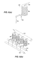
- FIGURES 6(a) and (b) illustrate still further embodiments according to the presently described embodiments
- FIGURES 7(a) and (b) illustrate still further embodiments according to the presently described embodiments.
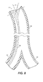
- FIGURE 8 illustrates a still further embodiment according to the presently described embodiments.
- the presently described embodiments use a curved channel of a spiral device to introduce a centrifugal force upon neutrally buoyant particles (e.g., particles having substantially the same density as water, or the fluid in which the particles reside) flowing in a fluid, e.g. water, to facilitate improved separation of such particles from the fluid.
- neutrally buoyant particles e.g., particles having substantially the same density as water, or the fluid in which the particles reside
- a tubular pinch effect causes the particles to flow in a tubular band.
- the introduced centrifugal force perturbs the tubular band (e.g. forces the tubular band to flow in a manner offset from a center of the channel), resulting in an asymmetric inertial migration of the band toward the inner wall of the channel.
- This force balance allows for focusing and compaction of suspended particulates into a narrow band for extraction.
- the separation principle contemplated herein implements a balance of the centrifugal and fluidic forces to achieve asymmetric inertial equilibrium near the inner sidewall. Angled impingement of the inlet stream towards the inner wall also allow for earlier band formation due to a Coanda effect where wall friction is used to attach the impinging flow
- the presently described embodiments relate to a membrane-free filtration technology that is capable of continuous flow and high throughput operation.
- the working principle relies primarily on purely fluidic flow in curved channel structures, eliminating the need for filter-interfaces or external force-fields.
- Balanced transverse force components concentrate and divert particle streams according to the designed size cut-off.
- This spiral flow filtration concept can address size and mass based separation of micro-particles, including biological agents.
- the design simplicity makes this device amenable both to inline integration with other downstream processes and to serve as stand-alone, high-throughput, macro-scale or fine micro-scale lab-on-chip applications.
- a curved channel 10 (e.g. a curved portion of a spiral) having a particle 12 flowing there through is shown.
- the forces include a lift force F W from the inner wall, a Saffman force F S , Magnus forces F m and a centrifugal force F cf .
- the centrifugal force F cf is generated as a function of the radius of curvature of the channel.
- this added centrifugal force F cf induces the slow secondary flow or Dean vortex flow (shown by the dashed arrows) which perturbs the symmetry of the regular tubular pinch effect. Particles are concentrated in the inner equilibrium of the velocity contour (shown in the dashed ellipses).
- fluidic shear in straight channels is known to generate lateral forces which cause inertial migration of particulates.
- G. Segré and A. Silberberg Nature, v. 189, p. 209 (1961 )
- D. Leighton and A. Acrivos Z. angew. Math. Phys., v. 36 p. 174 (1985 ), P. Cherukat, and J.B. McLaughlin, J. Fluid Mech., v. 263, p. 1 (1994 ), P. G. Saffman, J. Fluid Mech., v. 22, p. 385 (1965 ), S.I.
- ⁇ , V, a, and Re are respectively, the fluid viscosity, average channel velocity, particle radius, and channel Reynold's number given by:
- ⁇ r is the angular velocity given by ⁇ V/r and ⁇ V is the differential velocity across the particle S.I. Rubinow and J.B. Keller, J. Fluid Mech., v. 11, p. 447 (1961 ).
- F w dominates near the wall and achieves equilibrium with the combined effects of F s and F m to confine particles in a band.
- G. Segré and A. Silberberg, J. Fluid Mech., v. 14, p. 136 (1962 ) developed a reduced length parameter to scale this tubular pinch effect in a simple form
- R is the radius of curvature of the channel S. A. Berger, L. Talbot and L. -S. Yao, Ann. Rev. Fluid Mech., v. 15, p. 461 (1983 ).
- Particles in mid-elevation migrate transversely outward with the Dean vortex, are repelled by the wall lift, and continue to loop back along the top and bottom walls towards the inside wall.
- the combined Saffman and Magnus forces are large in comparison to the viscous drag of the Dean vortex so particles are trapped in a force minimum located adjacent and closer to the inner wall.
- the contemplated tubular band is formed as a function of at least one of fluid viscosity, average channel velocity, particle radius, fluid density, hydraulic diameter of channel, angular velocity, and differential velocity across particles.
- the tubular band is offset from the center of the channel as a function of a radius of curvature of the spiral channel.
- the configuration and operation of the system is a function of the factors contemplated, for example, by Equation 4. These factors or parameters are highly scalable and will vary as a matter of application in the range from micro-scale devices to macro-scale devices. Examples are provided herein; however, other implementations are contemplated.
- Filtration capacity such as sample, volume, hydraulic retention times, filtration rate, cut-off particle size, and concentration factor can be adjusted by tailoring fluidic and dimensional parameters.
- Extension to size separation would merely involve tailoring of the flow parameters for a monotonic range of particle sizes and providing capture channels in sequential manner along the spiral channel.
- This membrane-free device has the desirable combinations of high-throughput and low cost, making it inherently suited for preparative filtration in the range of micro-scale to macro-scale applications.
- Design technique is provided for a spiral structure for rapid fluidic separation of neutrally buoyant particles without a membrane.
- Double nested spiral channels can be implemented to compact band successively from both sides.
- Contemplated structures may be used for other applications in water including: IC fab reclaim, cooling tower water, MBR (membrane bio reactor), pre-treatment for RO (reverse osmosis).
- the described systems generally include an inlet to receive at least a portion of the fluid containing the neutrally buoyant particles, a spiral channel within which the fluid flows in a manner such that the neutrally buoyant particles flow in a tubular band offset from a center of the channel, a first outlet for the fluid within which the tubular band flows and a second outlet for the remaining fluid.
- the method includes receiving at least a portion of the fluid containing the neutrally buoyant particles at an inlet, establishing a flow of the fluid in a spiral channel wherein the neutrally buoyant particles flow in a tubular band through the spiral channel in an asymmetric manner, outputting the fluid within which the tubular band flows through a first outlet of the channel and outputting the remaining fluid through a second outlet of the spiral channel.
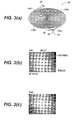
- FIG. 3(a) illustrates a spiral structure 30 that may be implemented in accordance with the presently described embodiments.
- This structure 30 is a double nested structure wherein a first spiral channel is nested with a second spiral channel. That is, the inlet 32 is connected to a spiral channel that spirals to the center of the structure 30 and then spirals back out to the outer periphery of the structure 30 - without interruption other than a change in direction. So, the outlet 34, having a first outlet portion 36 and a second outlet portion 38, is disposed on the outer periphery, as opposed to the center of the structure 30.
- the inlet could provide for an angled or inclined entry of fluid to the system to facilitate quicker formation of the tubular band along an inner wall of the spiral channel. This is the result of the Coanda effect where wall friction is used to attach the impinging flow.
- the channel 10 has an inlet 11 wherein the inlet stream is angled toward the inner wall by an angle ⁇ .
- the tubular band 18 is thus formed earlier for egress out of the outlet 14.
- the second outlet 16 for the remaining fluid in which the band 18 does not flow is also shown.
- the inlet angle may be realized using any suitable mechanism or technique.
- the noted lateral forces across the spiral channel geometry transform a relatively homogeneous distribution of particles at the inlet 32 into an ordered band at the outlet 34.
- particles are collected at an inside outlet 36 and the effluent (water) are collected at an outside outlet 38.
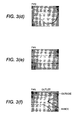
- Sequential images along the fluidic path are shown. Images are rotated and mirrored to match their flow directions for comparison. The bottom sides are toward the center of the spirals. The fluid runs left to right or bottom to top at the mean fluidic velocity of 92 mm / s. As shown, a dispersed particle suspension was introduced into an inlet (P#1) ( Figure 3(b) ) with an average flow velocity of 92 mm / s. After two spiral turns (P#2) ( Figure 3(c) ), the particles closest to the inner wall (lower boundary) have started to concentrate at 0.6w from the channel center where w is a half of the channel width.
- particle concentration shows a band with a sharp edge on the inside and a more diffuse edge on the outside.
- this (P#3) ( Figure 3(d) ) is a transition point to change the flow from clockwise to counter-clockwise direction. This transition has beneficial effects on compacting the band of particles.
- the sharp edge of the band is switched to the outside and the continuing lateral force acts to mitigate against the dispersive effects of Brownian motion and diffusion.
- the diffuse outside edge of the band is switched to the inside and is now subjected to the compacting effect of the centrifugal and lift force induced effect.
- Particle counting of collected samples after filtration confirm the results from the preceding observation. After the samples were filtered with different flow rates, the collected samples were diluted to 50 times for coulter counting (Z2TM COULTER COUNTER®, Beckman Coulter, CA, USA). The concentration of particles from the outer outlet decreased as the flow velocity increased. As discussed previously, the efficiency of filtration depends on the corresponding length L that is a function of (particle velocity). Faster flow velocity improved filtration efficiency (particle capture efficiency) from 64.7% at 23 mm/s to 99.1% at 92 mm / s. The separation factor or ratio of concentrations of the particle and effluent outlets exceeds 300x, and can be further optimized.
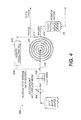
- Figure 4 illustrates the implementation of a spiral separator device according to the presently described embodiments within a purification system 400.
- the system includes a screen 402, a flash mixer 405, and a reduced coagulation tank 404.
- the spiral device 408 according to the presently described embodiments includes an inlet 410 as well as a first outlet 412 and a second outlet 414. Also shown in the system 400 is a recirculation channel or path 416 which is disposed between the inlet 410 and the coagulation tank 404.
- fluid containing neutrally buoyant particles is received in the system and first filtered through the screen 402.
- the filtered water is then flash-mixed 405 before being introduced into the spiral device 408 through inlet 410.
- the tubular band of neutrally buoyant particles is maintained to flow in an asymmetric manner, relative to the center of the channel. This asymmetry allows for convenient separation of the fluid within which the tubular band flows (which is output through outlet 412) and the remaining fluid (which is output through outlet 414).
- the concentrate stream is optionally re-circulated back, for example, to the reduced coagulation tank from outlet 412 to increase water recovery.
- a purification system 500 includes a two-stage spiral separation system to isolate particles of different sizes.
- the particles are isolated in a 1 to 10 micrometer range.
- the system includes an input water source 502 connecting to a spiral separator 504 having an inlet 506, as well as a first outlet 508 and a second outlet 510.
- the second outlet 510 is connected to a second spiral separator 520 by way of an inlet 522.
- the spiral separator 520 includes a first outlet 524 and a second outlet 526 as shown.
- the system 500 with the cascaded spiral stages facilitates a first separation of particles between those of greater than 10 micrometers being output from the first spiral separator in a waste stream and particles less than 10 micrometers being input to the second spiral separator 520 for further processing.
- the second spiral separator then separates particles greater than 1 micrometer and outputs fluid within which those particles reside by way of outlet 524.
- the remaining fluid or effluent is output through outlet 526.
- the system 500 is able to isolate particles between 1 and 10 micrometers for various sampling processing. This concept can be extended by continued cascading of spiral structures with smaller size cut-offs to achieve fractionation of particles with decreasing size ranges.
- a spiral device 600 according to the presently described embodiments is illustrated.
- the spiral device 600 takes the form of a helical spiral.
- the spiral body portion of the device 604 is a helical spiral that has an inlet 606, a first outlet 608 and a second outlet 610.
- a spiral device such as that shown in Figure 6(a) can be disposed in a parallel arrangement to increase throughput of the system.
- spiral devices 600 are all connected to an input main 620 from a fluid manifold and the respective first outlets of the devices 600 are connected to a first outlet main 622.
- the second outlets of the devices 600 are connected to a second outlet main 624.
- Figure 7(a) shows a spiral device 700 that is a spiral wound device.
- This device 700 includes a spirally wound body 704 having inlet 706, a first outlet 708 and a second outlet 710.
- the device 700 as shown in Figure 7(b) , may be disposed in a system wherein a plurality of devices 700 are connected in parallel to a water inlet main 720 from a fluid manifold.
- the first outlet lines for the devices are connected to a first outlet main 722.
- the second outlet lines of the devices 700 are connected to a second outlet main 724.
- spiral devices contemplated herein may take a variety of forms including the form of any of the spiral devices described in connection with co-pending and commonly assigned U.S. Application Serial No. 11/606,460, filed November 30, 2006 , entitled “Particle Separation and Concentration System", which is incorporated herein in its entirety by this reference, provided that such devices are configured, dimensioned and operated to advantageously address neutrally buoyant particles within fluid.
- appropriate modifications would be made to such devices to accommodate the presently described embodiments.
- any of the spiral devices described or contemplated herein may be disposed in a cascaded manner, as shown in Figure 5 , or in a parallel manner, as shown in Figures 6(a), 6(b) , 7(a) and 7(b) . Still further, any suitable material may be used to form the spiral devices contemplated herein.
Landscapes
- Chemical & Material Sciences (AREA)
- Chemical Kinetics & Catalysis (AREA)
- Health & Medical Sciences (AREA)
- Clinical Laboratory Science (AREA)
- Dispersion Chemistry (AREA)
- Analytical Chemistry (AREA)
- General Health & Medical Sciences (AREA)
- Hematology (AREA)
- Physics & Mathematics (AREA)
- Fluid Mechanics (AREA)
- Cyclones (AREA)
- Separation Of Solids By Using Liquids Or Pneumatic Power (AREA)
- Separating Particles In Gases By Inertia (AREA)
- Physical Or Chemical Processes And Apparatus (AREA)
- Separation Using Semi-Permeable Membranes (AREA)
- Indicating Or Recording The Presence, Absence, Or Direction Of Movement (AREA)
Abstract
Description
- Conventional municipal water treatment (MWT) and other types of water purification systems include multi-stage filtration and sequential process steps for coagulation, flocculation, and sedimentation. A minimum of two stages of filtration typically include coarse 2-3 mm mesh filters at the inlet and 20-40µm multi-media filters for finishing, although many utilities have more intermediate filtration steps. Neutrally buoyant particles (e.g. particles having substantially the same density as water) can only be filtered or electro-chemically modified for sedimentation. Separation of these types of particles from water is very difficult. Moreover, such particles are typically TOC (total organic carbon) and contribute to major turbidity problems.
- A spiral fluidic device useful for membrane-free filtration and separation has been developed. was described in
U.S. Application Serial No. 11/606,460, filed November 30, 2006 - In one aspect of the presently described embodiments, the system comprises an inlet to receive at least a portion of the fluid containing the neutrally buoyant particles, a spiral channel within which the fluid flows in a manner such that the neutrally buoyant particles flow in a tubular band offset from a center of the channel, a first outlet for the fluid within which the tubular band flows, and, a second outlet for the remaining fluid or effluent.
- In another aspect of the presently described embodiments, the inlet is angled to facilitate earlier formation of the tubular band along an inner wall of the spiral channel using a Coanda effect where wall friction helps to attach impinging flow.
- In another aspect of the presently described embodiments, the system further comprises a second spiral channel nested with the spiral channel such that the tubular band is narrowed as a result of flowing through the second spiral channel.
- In another aspect of the presently described embodiments, the system further comprises a second inlet connected to the second outlet of the spiral channel to receive the remaining fluid, a second spiral channel within which the remaining fluid flows such that the remaining neutrally buoyant particles flow in a second tubular band offset from the center of the second channel, a third outlet for the fluid within which the second tubular band flows, and, a fourth outlet for more remaining fluid.
- In another aspect of the presently described embodiments, the remaining neutrally buoyant particles are of a different size than the neutrally buoyant particles output through the first outlet.
- In another aspect of the presently described embodiments, the system further comprises a second spiral channel within which at least another portion of the fluid flows.
- In another aspect of the presently described embodiments, the system further comprises a recirculation channel between the first outlet and the inlet.
- In another aspect of the presently described embodiments, the tubular band is formed as a function of at least one of fluid viscosity, average channel velocity, particle radius, fluid density, hydraulic diameter of channel, angular velocity, and differential velocity across particles.
- In another aspect of the presently described embodiments, the tubular band is offset from the center of the channel as a function of a radius of curvature of the spiral channel.
- In another aspect of the presently described embodiments, the spiral channel is a spiral wound structure.
- In another aspect of the presently described embodiments, the spiral channel is a helical spiral structure.
- In another aspect of the presently described embodiments, the method comprises receiving at least a portion of the fluid containing the neutrally buoyant particles at an inlet, establishing a flow of the fluid in a spiral channel wherein the neutrally buoyant particles flow in a tubular band through the spiral channel in an asymmetric manner, outputting the fluid within which the tubular band flows through a first outlet of the channel, and, outputting the remaining fluid through a second outlet of the spiral channel.
- In another aspect of the presently described embodiments, the fluid is received at an angle to facilitate the formation of the tubular band along an inner wall of the spiral channel.
- In another aspect of the presently described embodiments, the method further comprises establishing a second flow of the fluid through a second spiral channel nested with the spiral channel to narrow the tubular band.
- In another aspect of the presently described embodiments, the method further comprises establishing a flow of the remaining fluid in a second spiral channel cascaded with the first spiral channel to separate neutrally buoyant particles of a different size than the neutrally buoyant particles output through the first outlet.
- In another aspect of the presently described embodiments, the method further comprises establishing a flow of at least another portion of fluid in a second spiral channel.
- In another aspect of the presently described embodiments, the method further comprises re-circulating in the system at least a portion of the fluid output through the first outlet.
- In another aspect of the presently described embodiments, the flow of neutrally buoyant particles in a tubular band is adjustable as a function of fluid viscosity, average channel velocity, particle radius, fluid density, hydraulic diameter of the channel, angular velocity, and differential velocity across particles.
- In another aspect of the presently described embodiments, the asymmetric manner of flow of the tubular band is a function of a radius of curvature of the spiral channel.
-
FIGURE 1 is a representation of a particle flowing through a channel and forces acting thereon; -
FIGURES 2(a) and (b) illustrate a selected quantification of particle extraction; -
FIGURES 3(a)-(f) illustrate an embodiment of a spiral device according to the presently described embodiments; -
FIGURE 4 illustrates another embodiment according to the presently described embodiments; -
FIGURE 5 illustrates still another embodiment according to the presently described embodiments; -
FIGURES 6(a) and (b) illustrate still further embodiments according to the presently described embodiments; -
FIGURES 7(a) and (b) illustrate still further embodiments according to the presently described embodiments; and, -
FIGURE 8 illustrates a still further embodiment according to the presently described embodiments. - The presently described embodiments use a curved channel of a spiral device to introduce a centrifugal force upon neutrally buoyant particles (e.g., particles having substantially the same density as water, or the fluid in which the particles reside) flowing in a fluid, e.g. water, to facilitate improved separation of such particles from the fluid. As these neutrally buoyant particles flow through the channel, a tubular pinch effect causes the particles to flow in a tubular band. The introduced centrifugal force perturbs the tubular band (e.g. forces the tubular band to flow in a manner offset from a center of the channel), resulting in an asymmetric inertial migration of the band toward the inner wall of the channel. This force balance allows for focusing and compaction of suspended particulates into a narrow band for extraction. The separation principle contemplated herein implements a balance of the centrifugal and fluidic forces to achieve asymmetric inertial equilibrium near the inner sidewall. Angled impingement of the inlet stream towards the inner wall also allow for earlier band formation due to a Coanda effect where wall friction is used to attach the impinging flow
- The presently described embodiments relate to a membrane-free filtration technology that is capable of continuous flow and high throughput operation. The working principle relies primarily on purely fluidic flow in curved channel structures, eliminating the need for filter-interfaces or external force-fields. Balanced transverse force components concentrate and divert particle streams according to the designed size cut-off. This spiral flow filtration concept can address size and mass based separation of micro-particles, including biological agents. The design simplicity makes this device amenable both to inline integration with other downstream processes and to serve as stand-alone, high-throughput, macro-scale or fine micro-scale lab-on-chip applications.
- With reference to
Figure 1 , a curved channel 10 (e.g. a curved portion of a spiral) having aparticle 12 flowing there through is shown. As can be seen, asymmetric tubular pinch effects in the channel -- created by various forcesare shown. The forces include a lift force FW from the inner wall, a Saffman force FS, Magnus forces Fm and a centrifugal force Fcf. It should be appreciated that the centrifugal force Fcf is generated as a function of the radius of curvature of the channel. In this regard, this added centrifugal force Fcf induces the slow secondary flow or Dean vortex flow (shown by the dashed arrows) which perturbs the symmetry of the regular tubular pinch effect. Particles are concentrated in the inner equilibrium of the velocity contour (shown in the dashed ellipses). - More specifically, fluidic shear in straight channels is known to generate lateral forces which cause inertial migration of particulates. G. Segré and A. Silberberg, Nature, v. 189, p. 209 (1961), G. Segré and A. Silberberg, J. Fluid Mech., v. 14, p. 136 (1962), D. Leighton and A. Acrivos, Z. angew. Math. Phys., v. 36 p. 174 (1985), P. Cherukat, and J.B. McLaughlin, J. Fluid Mech., v. 263, p. 1 (1994), P. G. Saffman, J. Fluid Mech., v. 22, p. 385 (1965), S.I. Rubinow and J.B. Keller, J. Fluid Mech., v. 11, p. 447 (1961), B. P. Ho and L. G. Leal, J. Fluid Mech., v. 65, p. 365 (1974), P. Vasseur and R. G. Cox, J. Fluid Mech., v. 78, p. 385 (1976), J. Feng, H. H. Hu and D. D. Joseph, J. Fluid Mech., v. 277, p. 271 (1994), E. Ashmolov, J. Fluid Mech., v. 381, p. 63 (1999), E. Ashmolov, Phys. Fluids, v. 14, p. 15 (2002), J.-P. Matas, J. F. Morris and E. Guazzelli, J. Fluid Mech., v. 515, p. 171 (2004), B. H. Yang, J. Wang, D. D. Joseph, H. H. Hu, T. -W. Pan and R. Glowinski, J. Fluid Mech., v. 540, p. 109 (2005), E. E. Michaelides, J. Fluids Eng., v. 125, p. 209, (2003), P. Cherukat and J. B. McLaughlin, Int. J. Multiphase Flow, v. 16, p. 899 (1990), P. Cherukat, J. B. McLaughlin and A. L. Graham, Int. J. Multiphase Flow, v. 20, p. 339 (1994).
- G. Segré and A. Silberberg, Nature, v. 189, p. 209 (1961), and G. Segré and A. Silberberg, J. Fluid Mech., v. 14, p. 136 (1962), experimentally demonstrated a tubular pinch effect where neutrally buoyant particles migrate to form a symmetric band that is 0.6D wide, where D is the channel diameter. In quadratic Poiseuille flow, three contributions have explained the lateral migration of a rigid sphere. The wall lift, FW, acts to repel particulates from the wall due to lubrication. D. Leighton and A. Acrivos, Z. angew. Math. Phys., v. 36 p. 174 (1985), P. Cherukat, and J.B. McLaughlin, J. Fluid Mech., v. 263, p. 1 (1994). The second contribution is the Saffman inertial lift, FS, towards the wall due to shear slip,
-

- where η, V, a, and Re are respectively, the fluid viscosity, average channel velocity, particle radius, and channel Reynold's number given by:
-

- with ρ and D being the fluid density and hydraulic diameter of the channel. [10, 14]. The third is the Magnus force, Fm, due to particle rotation towards the wall,
-

- where Ωr is the angular velocity given by ΔV/r and ΔV is the differential velocity across the particle S.I. Rubinow and J.B. Keller, J. Fluid Mech., v. 11, p. 447 (1961). Fw dominates near the wall and achieves equilibrium with the combined effects of Fs and Fm to confine particles in a band. G. Segré and A. Silberberg, J. Fluid Mech., v. 14, p. 136 (1962), developed a reduced length parameter to scale this tubular pinch effect in a simple form,
-

- where / is the actual channel length and d is the hydraulic channel radius. In curvilinear channel geometry, a centrifugal force, Fcf, modifies the symmetric tubular pinch effect. The fluid inertia from this force causes a secondary transverse flow or Dean vortex, P. Cherukat and J. B. McLaughlin, Int. J. Multiphase Flow, v. 16, p. 899 (1990), P. Cherukat, J. B. McLaughlin and A. L. Graham, Int. J. Multiphase Flow, v. 20, p. 339 (1994), S. A. Berger, L. Talbot and L. -S. Yao, Ann. Rev. Fluid Mech., v. 15, p. 461 (1983), Yu. P. Gupalo, Yu. V. Martynov and Yu. S. Ryazantsev, Fluid Dyn., 12, 109 (1977) which is a double recirculation as shown by the dot arrows in
Fig. 1 . The Dean number is a measure of the strength of this recirculation: -

- where R is the radius of curvature of the channel S. A. Berger, L. Talbot and L. -S. Yao, Ann. Rev. Fluid Mech., v. 15, p. 461 (1983). Particles in mid-elevation migrate transversely outward with the Dean vortex, are repelled by the wall lift, and continue to loop back along the top and bottom walls towards the inside wall. The combined Saffman and Magnus forces are large in comparison to the viscous drag of the Dean vortex so particles are trapped in a force minimum located adjacent and closer to the inner wall.
- So, it is apparent that the contemplated tubular band is formed as a function of at least one of fluid viscosity, average channel velocity, particle radius, fluid density, hydraulic diameter of channel, angular velocity, and differential velocity across particles. Moreover, as noted above, the tubular band is offset from the center of the channel as a function of a radius of curvature of the spiral channel. So, the configuration and operation of the system is a function of the factors contemplated, for example, by
Equation 4. These factors or parameters are highly scalable and will vary as a matter of application in the range from micro-scale devices to macro-scale devices. Examples are provided herein; however, other implementations are contemplated. - Implementation of the methodology described herein results in a system whereby particles can be separated within a spiral channel and output in a manner so as to separate particles of selected sizes from an effluent stream. For example, with reference to
Figure 2 , a Coulter counter quantification of such particle extraction is illustrated. At 92 mm/s flow velocity, the concentration ratio of extracted particles in aparticulate band 20, as shown inFigure 2(b) , is 300 times that of theeffluent 22 that is being output by thespiral channel 24. Experimentally, this calculates to a 99.1 % efficiency of particle removal using the presently described embodiments. - Other advantages of the presently described embodiments include:
- 1) Filtration capacity such as sample, volume, hydraulic retention times, filtration rate, cut-off particle size, and concentration factor can be adjusted by tailoring fluidic and dimensional parameters.
- 2) Extension to size separation would merely involve tailoring of the flow parameters for a monotonic range of particle sizes and providing capture channels in sequential manner along the spiral channel.
- 3) Ability to cascade several of these spiral structures, each tailored for a decreasing particle size range cut-off.
- 4) Design simplicity making this device amenable both to inline integration with other downstream processes and to serve as a stand-alone application.
- 5) Large dynamic size range in its filtration capacity makes it suited for both high-throughput macroscale and fine micro-scale lab-on-chip applications.
- 6) Parallelization of modular units can be realized for higher throughput.
- 7) This membrane-free device has the desirable combinations of high-throughput and low cost, making it inherently suited for preparative filtration in the range of micro-scale to macro-scale applications.
- 8) Design technique is provided for a spiral structure for rapid fluidic separation of neutrally buoyant particles without a membrane.
- 9) Double nested spiral channels can be implemented to compact band successively from both sides.
- 10) Highly scalable implementation based on reduced length formula is realized.
- 11) Flocculation and sedimentation steps can be eliminated in conventional water treatment.
- 12) Contemplated structures may be used for other applications in water including: IC fab reclaim, cooling tower water, MBR (membrane bio reactor), pre-treatment for RO (reverse osmosis).
- It should be appreciated that these advantages may be achieved in a variety of different embodiments. These embodiments will vary as a function of the parameters noted above which are controllable and/or configurable through channel design and operational parameters. Nonetheless, the described systems generally include an inlet to receive at least a portion of the fluid containing the neutrally buoyant particles, a spiral channel within which the fluid flows in a manner such that the neutrally buoyant particles flow in a tubular band offset from a center of the channel, a first outlet for the fluid within which the tubular band flows and a second outlet for the remaining fluid. So, in operation, the method includes receiving at least a portion of the fluid containing the neutrally buoyant particles at an inlet, establishing a flow of the fluid in a spiral channel wherein the neutrally buoyant particles flow in a tubular band through the spiral channel in an asymmetric manner, outputting the fluid within which the tubular band flows through a first outlet of the channel and outputting the remaining fluid through a second outlet of the spiral channel.
- In this regard,
Figure 3(a) illustrates aspiral structure 30 that may be implemented in accordance with the presently described embodiments. Thisstructure 30 is a double nested structure wherein a first spiral channel is nested with a second spiral channel. That is, theinlet 32 is connected to a spiral channel that spirals to the center of thestructure 30 and then spirals back out to the outer periphery of the structure 30 - without interruption other than a change in direction. So, theoutlet 34, having afirst outlet portion 36 and asecond outlet portion 38, is disposed on the outer periphery, as opposed to the center of thestructure 30. - It should also be appreciated that the inlet could provide for an angled or inclined entry of fluid to the system to facilitate quicker formation of the tubular band along an inner wall of the spiral channel. This is the result of the Coanda effect where wall friction is used to attach the impinging flow. With reference to
Figure 8 , thechannel 10 has aninlet 11 wherein the inlet stream is angled toward the inner wall by an angle θ. Thetubular band 18 is thus formed earlier for egress out of theoutlet 14. Of course, thesecond outlet 16 for the remaining fluid in which theband 18 does not flow is also shown. It should be understood that the inlet angle may be realized using any suitable mechanism or technique. - With reference back now to
Figure 3(a) according to the presently described embodiments, the noted lateral forces across the spiral channel geometry transform a relatively homogeneous distribution of particles at theinlet 32 into an ordered band at theoutlet 34. After spiral circulation, particles are collected at aninside outlet 36 and the effluent (water) are collected at anoutside outlet 38. - Sequential images along the fluidic path are shown. Images are rotated and mirrored to match their flow directions for comparison. The bottom sides are toward the center of the spirals. The fluid runs left to right or bottom to top at the mean fluidic velocity of 92 mm/s. As shown, a dispersed particle suspension was introduced into an inlet (P#1) (
Figure 3(b) ) with an average flow velocity of 92 mm/s. After two spiral turns (P#2) (Figure 3(c) ), the particles closest to the inner wall (lower boundary) have started to concentrate at 0.6w from the channel center where w is a half of the channel width. At the transitional point after 12 turns (P#3) (Figure 3(d) ), particle concentration shows a band with a sharp edge on the inside and a more diffuse edge on the outside. It should be noted that this (P#3) (Figure 3(d) ) is a transition point to change the flow from clockwise to counter-clockwise direction. This transition has beneficial effects on compacting the band of particles. After the transition point, the sharp edge of the band is switched to the outside and the continuing lateral force acts to mitigate against the dispersive effects of Brownian motion and diffusion. On the other hand, the diffuse outside edge of the band is switched to the inside and is now subjected to the compacting effect of the centrifugal and lift force induced effect. As a result, a sharp edge is developed as observed (P#4) (Figure 3(e) ). The concentrated band of particles are diverted into the inside outlet (P# 5, L= 34.2) (Figure 3(f) ) whilst the effluent stream is routed into the outside outlet. Segré and Silberberg showed that the reduced length parameter for one order of concentration difference should be L>9 G. Segré and A. Silberberg, J. Fluid Mech., c. 14, p. 136 (1962). The concentration difference between the collected samples is expected be about two orders of magnitude. The resultant band is less than 0.2D wide and could be further compacted. - Particle counting of collected samples after filtration confirm the results from the preceding observation. After the samples were filtered with different flow rates, the collected samples were diluted to 50 times for coulter counting (Z2™ COULTER COUNTER®, Beckman Coulter, CA, USA). The concentration of particles from the outer outlet decreased as the flow velocity increased. As discussed previously, the efficiency of filtration depends on the corresponding length L that is a function of (particle velocity). Faster flow velocity improved filtration efficiency (particle capture efficiency) from 64.7% at 23 mm/s to 99.1% at 92 mm/s. The separation factor or ratio of concentrations of the particle and effluent outlets exceeds 300x, and can be further optimized. The important effect of the spiral geometry is to focus the particles into a narrow band through the asymmetric tubular pinch effect. This nested double spiral (
Figure 3(a) ) acts to sequentially compact each side of the band resulting in a sharper and narrower band than is predicted by the tubular pinch effect alone. - In another embodiment,
Figure 4 illustrates the implementation of a spiral separator device according to the presently described embodiments within apurification system 400. As shown, the system includes ascreen 402, aflash mixer 405, and a reducedcoagulation tank 404. Thespiral device 408 according to the presently described embodiments includes aninlet 410 as well as afirst outlet 412 and asecond outlet 414. Also shown in thesystem 400 is a recirculation channel orpath 416 which is disposed between theinlet 410 and thecoagulation tank 404. - In operation, fluid containing neutrally buoyant particles is received in the system and first filtered through the
screen 402. The filtered water is then flash-mixed 405 before being introduced into thespiral device 408 throughinlet 410. As the fluid flows in thespiral device 408, the tubular band of neutrally buoyant particles is maintained to flow in an asymmetric manner, relative to the center of the channel. This asymmetry allows for convenient separation of the fluid within which the tubular band flows (which is output through outlet 412) and the remaining fluid (which is output through outlet 414). The concentrate stream is optionally re-circulated back, for example, to the reduced coagulation tank fromoutlet 412 to increase water recovery. - With reference now to
Figure 5 , a further embodiment to the presently described embodiments is shown. In this embodiment, apurification system 500 includes a two-stage spiral separation system to isolate particles of different sizes. In the example system shown, the particles are isolated in a 1 to 10 micrometer range. As shown, the system includes aninput water source 502 connecting to aspiral separator 504 having aninlet 506, as well as afirst outlet 508 and asecond outlet 510. Thesecond outlet 510 is connected to asecond spiral separator 520 by way of aninlet 522. Thespiral separator 520 includes afirst outlet 524 and asecond outlet 526 as shown. - In operation, the
system 500 with the cascaded spiral stages facilitates a first separation of particles between those of greater than 10 micrometers being output from the first spiral separator in a waste stream and particles less than 10 micrometers being input to thesecond spiral separator 520 for further processing. The second spiral separator then separates particles greater than 1 micrometer and outputs fluid within which those particles reside by way ofoutlet 524. The remaining fluid or effluent is output throughoutlet 526. In this manner, thesystem 500 is able to isolate particles between 1 and 10 micrometers for various sampling processing. This concept can be extended by continued cascading of spiral structures with smaller size cut-offs to achieve fractionation of particles with decreasing size ranges. - With reference now to
Figures 6 (a) and (b) , a still further embodiment is shown. InFigure 6 , aspiral device 600 according to the presently described embodiments is illustrated. In this embodiment, thespiral device 600 takes the form of a helical spiral. In this regard, the spiral body portion of thedevice 604 is a helical spiral that has aninlet 606, afirst outlet 608 and asecond outlet 610. As shown inFigure 6(b) , a spiral device such as that shown inFigure 6(a) can be disposed in a parallel arrangement to increase throughput of the system. As shown,spiral devices 600 are all connected to an input main 620 from a fluid manifold and the respective first outlets of thedevices 600 are connected to a first outlet main 622. The second outlets of thedevices 600 are connected to a second outlet main 624. - With reference to
Figures 7(a) through 7(b) , a similar system is shown. However, the embodiment ofFigure 7(a) shows aspiral device 700 that is a spiral wound device. Thisdevice 700 includes aspirally wound body 704 havinginlet 706, afirst outlet 708 and asecond outlet 710. As with the embodiment illustrated inFigures 6(a) and 6(b) , thedevice 700, as shown inFigure 7(b) , may be disposed in a system wherein a plurality ofdevices 700 are connected in parallel to a water inlet main 720 from a fluid manifold. Similarly, the first outlet lines for the devices are connected to a first outlet main 722. The second outlet lines of thedevices 700 are connected to a second outlet main 724. - It should be appreciated that the spiral devices contemplated herein may take a variety of forms including the form of any of the spiral devices described in connection with co-pending and commonly assigned
U.S. Application Serial No. 11/606,460, filed November 30, 2006 Figure 5 , or in a parallel manner, as shown inFigures 6(a), 6(b) ,7(a) and 7(b) . Still further, any suitable material may be used to form the spiral devices contemplated herein.
Claims (15)
- A system for separation of neutrally buoyant particles from a fluid, the system comprising:an inlet to receive at least a portion of the fluid containing the neutrally buoyant particles;a spiral channel within which the fluid flows in a manner such that the neutrally buoyant particles flow in a tubular band offset from a center of the channel;a first outlet for the fluid within which the tubular band flows; and,a second outlet for the remaining fluid.
- The system as set forth in claim 1 wherein the inlet is angled to facilitate earlier formation of the tubular band along an inner wall of the spiral channel.
- The system as set forth in claim 1 further comprising a second spiral channel nested with the spiral channel such that the tubular band is narrowed as a result of flowing through the second spiral channel.
- The system as set forth in claim 1 further comprising:a second inlet connected to the second outlet of the spiral channel to receive the remaining fluid;a second spiral channel within which the remaining fluid flows such that the remaining neutrally buoyant particles flow in a second tubular band offset from the center of the second channel;a third outlet for the fluid within which the second tubular band flows; and,a fourth outlet for more remaining fluid.
- The system as set forth in claim 4 wherein the remaining neutrally buoyant particles are of a different size than the neutrally buoyant particles output through the first outlet.
- The system as set forth in claim 1 further comprising a second spiral channel within which at least another portion of the fluid flows.
- The system as set forth in claim 1 further comprising a recirculation channel between the first outlet and the inlet.
- The system as set forth in claim 1 wherein the tubular band is formed as a function of at least one of fluid viscosity, average channel velocity, particle radius, fluid density, hydraulic diameter of channel, angular velocity, and differential velocity across particles.
- The system as set forth in claim 1 wherein the tubular band is offset from the center of the channel as a function of a radius of curvature of the spiral channel.
- The system as set forth in claim 1 wherein the spiral channel is a spiral wound structure.
- The system as set forth in claim 1 wherein the spiral channel is a helical spiral structure.
- A method for separating neutrally buoyant particles from a fluid, the method comprising:receiving at least a portion of the fluid containing the neutrally buoyant particles at an inlet;establishing a flow of the fluid in a spiral channel wherein the neutrally buoyant particles flow in a tubular band through the spiral channel in an asymmetric manner;outputting the fluid within which the tubular band flows through a first outlet of the channel; and,outputting the remaining fluid through a second outlet of the spiral channel.
- The method as set forth in claim 12 wherein the fluid is received at an angle to facilitate the formation of the tubular band along an inner wall of the spiral channel.
- The method as set forth in claim 12 further comprising establishing a second flow of the fluid through a second spiral channel nested with the spiral channel to narrow the tubular band.
- The method as set forth in claim 14 further comprising establishing a flow of the remaining fluid in a second spiral channel cascaded with the first spiral channel to separate neutrally buoyant particles of a different size than the neutrally buoyant particles output through the first outlet.
Applications Claiming Priority (1)
| Application Number | Priority Date | Filing Date | Title |
|---|---|---|---|
| US11/936,729 US10052571B2 (en) | 2007-11-07 | 2007-11-07 | Fluidic device and method for separation of neutrally buoyant particles |
Publications (3)
| Publication Number | Publication Date |
|---|---|
| EP2060312A2 true EP2060312A2 (en) | 2009-05-20 |
| EP2060312A3 EP2060312A3 (en) | 2011-03-16 |
| EP2060312B1 EP2060312B1 (en) | 2016-05-11 |
Family
ID=40379798
Family Applications (1)
| Application Number | Title | Priority Date | Filing Date |
|---|---|---|---|
| EP08168573.7A Not-in-force EP2060312B1 (en) | 2007-11-07 | 2008-11-07 | Fluidic device and method for separation of neutrally buoyant particles |
Country Status (6)
| Country | Link |
|---|---|
| US (1) | US10052571B2 (en) |
| EP (1) | EP2060312B1 (en) |
| JP (1) | JP5731096B2 (en) |
| CN (1) | CN101455922B (en) |
| SA (2) | SA08290648B1 (en) |
| SG (4) | SG171659A1 (en) |
Cited By (12)
| Publication number | Priority date | Publication date | Assignee | Title |
|---|---|---|---|---|
| CN101607152A (en) * | 2008-05-13 | 2009-12-23 | 帕洛阿尔托研究中心公司 | Fluid Structures for Membraneless Particle Separation |
| EP2260925A1 (en) * | 2009-06-12 | 2010-12-15 | Palo Alto Research Center Incorporated | Particle removal technology including precipitation and spiral separation |
| EP2465824A1 (en) * | 2010-12-20 | 2012-06-20 | Palo Alto Research Center Incorporated | Membrane bioreactor (MBR) configurations for wastewater treatment |
| US8276760B2 (en) | 2006-11-30 | 2012-10-02 | Palo Alto Research Center Incorporated | Serpentine structures for continuous flow particle separations |
| US8647479B2 (en) | 2009-06-12 | 2014-02-11 | Palo Alto Research Center Incorporated | Stand-alone integrated water treatment system for distributed water supply to small communities |
| US8931644B2 (en) | 2006-11-30 | 2015-01-13 | Palo Alto Research Center Incorporated | Method and apparatus for splitting fluid flow in a membraneless particle separation system |
| US9433880B2 (en) | 2006-11-30 | 2016-09-06 | Palo Alto Research Center Incorporated | Particle separation and concentration system |
| WO2016198880A1 (en) * | 2015-06-11 | 2016-12-15 | Heriot-Watt University | Microfluidic device |
| US9862624B2 (en) | 2007-11-07 | 2018-01-09 | Palo Alto Research Center Incorporated | Device and method for dynamic processing in water purification |
| US10052571B2 (en) | 2007-11-07 | 2018-08-21 | Palo Alto Research Center Incorporated | Fluidic device and method for separation of neutrally buoyant particles |
| CN110465339A (en) * | 2019-09-03 | 2019-11-19 | 浙江大学 | A method for particle localization in fluid-solid two-phase transport |
| WO2020102533A1 (en) * | 2018-11-15 | 2020-05-22 | Massachusetts Institute Of Technology | Multi-dimensional double spiral device and methods of use thereof |
Families Citing this family (47)
| Publication number | Priority date | Publication date | Assignee | Title |
|---|---|---|---|---|
| US8186913B2 (en) | 2007-04-16 | 2012-05-29 | The General Hospital Corporation | Systems and methods for particle focusing in microchannels |
| FR2931079B1 (en) * | 2008-05-13 | 2010-07-30 | Commissariat Energie Atomique | DEVICE AND METHOD FOR SEPARATING A SUSPENSION |
| US20100072142A1 (en) * | 2008-09-19 | 2010-03-25 | Palo Alto Research Center Incorporated | Method and system for seeding with mature floc to accelerate aggregation in a water treatment process |
| US20100314325A1 (en) * | 2009-06-12 | 2010-12-16 | Palo Alto Research Center Incorporated | Spiral mixer for floc conditioning |
| US20100314323A1 (en) * | 2009-06-12 | 2010-12-16 | Palo Alto Research Center Incorporated | Method and apparatus for continuous flow membrane-less algae dewatering |
| US20110108491A1 (en) * | 2009-11-10 | 2011-05-12 | Palo Alto Research Center Incorporated | Desalination using supercritical water and spiral separation |
| KR101207545B1 (en) | 2010-02-04 | 2012-12-03 | 주식회사 넥스비보 | Device for separating micro particles and method of separating micro particles |
| US9458489B2 (en) | 2010-03-04 | 2016-10-04 | Massachusetts Institute Of Technology | Microfluidics sorter for cell detection and isolation |
| US20110220371A1 (en) * | 2010-03-11 | 2011-09-15 | Halliburton Energy Services, Inc. | System and method for fluid treatment |
| US9994463B2 (en) | 2010-12-14 | 2018-06-12 | Palo Alto Research Center Incorporated | Electrocoagulation system |
| US8518235B2 (en) | 2010-12-14 | 2013-08-27 | Palo Alto Research Center Incorporated | All-electric coagulant generation system |
| WO2012128742A1 (en) * | 2011-03-18 | 2012-09-27 | Empire Technology Development Llc | Method of separating particulate matter from water using inertial forces |
| US9038725B2 (en) | 2012-07-10 | 2015-05-26 | Halliburton Energy Services, Inc. | Method and system for servicing a wellbore |
| US9789485B2 (en) | 2012-09-21 | 2017-10-17 | Massachusetts Institute Of Technology | Micro-fluidic device and uses thereof |
| US9804068B2 (en) * | 2012-09-28 | 2017-10-31 | University Of Maryland | Particle separation and concentration using spiral inertial filtration |
| JP6070124B2 (en) * | 2012-12-04 | 2017-02-01 | 株式会社Ihi | Solid-liquid separation method and apparatus |
| JP6070125B2 (en) * | 2012-12-04 | 2017-02-01 | 株式会社Ihi | Solid-liquid separation method and apparatus |
| US9624116B2 (en) | 2013-01-14 | 2017-04-18 | Palo Alto Research Center Incorporated | Systems and apparatus for removal of harmful algae blooms (HAB) and transparent exopolymer particles (TEP) |
| US10345199B2 (en) * | 2013-03-14 | 2019-07-09 | Sobru Solutions, Inc. | Sample acquisition system and method of use |
| US9908123B2 (en) | 2013-03-15 | 2018-03-06 | Palo Alto Research Center Incorporated | Method and system for stacking and sealing hydrodynamic separation layers |
| US10238995B2 (en) | 2013-06-14 | 2019-03-26 | Palo Alto Research Center Incorporated | HDS channel exit designs for improved separation efficiency |
| US9968869B2 (en) | 2013-06-14 | 2018-05-15 | Palo Alto Research Center Incorporated | Hydrodynamic separation using high aspect ratio channels |
| US9758407B2 (en) | 2013-12-20 | 2017-09-12 | Palo Alto Research Center Incorporated | Recycling activated sludge by hydrodynamic seperator (HDS) to enable high MLSS bioreactor to process high influent flow and/or high strength wastewater |
| EP3107995B1 (en) | 2014-02-18 | 2019-10-30 | Massachusetts Institute Of Technology | Biophysically sorted osteoprogenitors from culture expanded bone marrow derived mesenchymal stromal cells (mscs) |
| US20150290369A1 (en) * | 2014-04-10 | 2015-10-15 | Biomet Biologics, Llc | Inertial Cell Washing Device |
| CN104086010B (en) * | 2014-07-01 | 2015-11-04 | 浙江建设职业技术学院 | A kind of portable water purifying device |
| US10806845B2 (en) | 2014-09-17 | 2020-10-20 | Massachusetts Institute Of Technology | System and method for inertial focusing microfiltration for intra-operative blood salvage autotransfusion |
| CN107107076B (en) * | 2015-01-30 | 2019-11-08 | 安捷伦科技有限公司 | Impact centrifugal separator, manufacturing method thereof, and fraction collection system |
| ES2978196T3 (en) | 2015-09-03 | 2024-09-06 | Filterart Ltd | A conduit for use in a system for separating suspended particles in a fluid, and a method of designing such a conduit |
| CN105126988A (en) * | 2015-09-09 | 2015-12-09 | 贵州省福泉市隆翔矿业有限公司 | Multistage washing sand washer |
| CN108495809B (en) * | 2016-01-28 | 2023-04-25 | 明测生物医疗有限公司 | Multistage target cell enrichment using microfluidic devices |
| CN109791146A (en) * | 2016-07-07 | 2019-05-21 | 范德比尔特大学 | For detecting, capturing or removing the fluid means of disease material |
| US9969968B2 (en) | 2016-07-26 | 2018-05-15 | Palo Alto Research Center Incorporated | Hydrodynamic separation (HDS) for removing protist predators from algal crops |
| WO2018076274A1 (en) * | 2016-10-28 | 2018-05-03 | 喜美农业生技股份有限公司 | Substance separation method and system |
| IL251036A0 (en) | 2017-03-08 | 2017-06-29 | Aqua Hd Separation And Filtration Systems Ltd | System and method for separating particles suspended in a liquid |
| KR102184789B1 (en) * | 2017-07-19 | 2020-11-30 | 윌리엄 매스턴 주니어 제임스 | Low energy dynamic water purification system and water purification method |
| US10583820B2 (en) * | 2017-09-29 | 2020-03-10 | Bendix Commercial Vehicle Systems Llc | Effluent processing apparatus and method for a vehicle air brake charging system |
| CN107899955B (en) * | 2017-10-20 | 2020-07-10 | 东台市赐百年生物工程有限公司 | Hierarchical formula spirulina removes silt device |
| US20210053061A1 (en) * | 2017-12-15 | 2021-02-25 | Singapore University Of Technology And Design | Inertial cell focusing and sorting |
| JP7233848B2 (en) * | 2018-04-05 | 2023-03-07 | オルガノ株式会社 | Aggregation-separation control device, aggregation-separation control method, aggregation-separation treatment system, and aggregation-separation treatment method |
| WO2019232305A1 (en) | 2018-05-31 | 2019-12-05 | Donaldson Company, Inc. | Droplet sensors for fuel systems |
| JP2022518869A (en) * | 2018-06-01 | 2022-03-16 | モビエアー プライベート リミテッド | Filter media-free equipment and methods for cleaning particle-containing fluids using low-energy multi-flow splitter technology |
| JP7287622B2 (en) * | 2018-12-14 | 2023-06-06 | オルガノ株式会社 | Water quality measuring device and water quality measuring method |
| CN109939488B (en) * | 2019-04-29 | 2023-07-11 | 上海柏中观澈智能科技有限公司 | Fluid system for separating particulate matters in fluid and application thereof |
| CN113814008A (en) * | 2020-08-28 | 2021-12-21 | 上海交通大学 | Microfluidic channel structure, chip, particle ordered arrangement method and application |
| US12611619B2 (en) | 2020-11-25 | 2026-04-28 | Donaldson Company, Inc. | Hydrodynamic separator with optimal microchannel length |
| US12478899B2 (en) | 2021-06-02 | 2025-11-25 | Donaldson Company, Inc. | Maintenance of hydrodynamic separators |
Family Cites Families (121)
| Publication number | Priority date | Publication date | Assignee | Title |
|---|---|---|---|---|
| US3225523A (en) * | 1965-12-28 | Cyclone dust collector for removing particles from a fluid stream | ||
| US1133721A (en) * | 1912-08-23 | 1915-03-30 | William E Gregg | Sand washing and grading apparatus. |
| US1836758A (en) * | 1928-12-22 | 1931-12-15 | Peabody Engineering Corp | Apparatus for removing dust from gases |
| GB330163A (en) | 1929-07-05 | 1930-06-05 | Dorman Long And Company Ltd | Improvements in, or relating to, dust separators and collectors |
| GB386080A (en) | 1931-11-16 | 1933-01-12 | Howden James & Co Ltd | Improvements in or relating to centrifugal separators |
| US2426804A (en) * | 1944-06-14 | 1947-09-02 | Graver Tank & Mfg Co Inc | Liquid treatment tank with concentric compartments and with distributors below the bottom surface |
| US2615572A (en) * | 1946-08-26 | 1952-10-28 | Edwin T Hodge | Spiral separator |
| US2584976A (en) * | 1947-08-08 | 1952-02-12 | Mining Process & Patent Co | Apparatus for concentrating ores and the like |
| GB934423A (en) | 1958-11-07 | 1963-08-21 | Polysius Gmbh | Apparatus for classifying solids |
| ES312182A1 (en) | 1964-04-29 | 1965-07-16 | Fives Lille Cail | Pneumatic separation installation |
| FR1592545A (en) * | 1968-05-15 | 1970-05-19 | ||
| US3693791A (en) * | 1970-02-06 | 1972-09-26 | Brehm Dr Ingbureau Ag | Method of, and apparatus for, spiral air classification of solid particles in a gaseous carrier |
| GB1410704A (en) * | 1971-12-06 | 1975-10-22 | Messerschmitt Boelkow Blohm | Method of and apparatus for centrifugally separating matter suspended in a gaseous or liquid medium |
| US3893921A (en) * | 1973-11-27 | 1975-07-08 | Wheelabrator Frye Inc | Flocculation device for waste fluid treatment |
| US3948771A (en) * | 1973-11-30 | 1976-04-06 | Messerschmitt-Bolkow-Blohm Gmbh | Method and apparatus for separating suspended matter from a fluid by centrifugal force |
| US3933642A (en) * | 1974-03-18 | 1976-01-20 | Wilson George E | Flocculation apparatus |
| DE2538190C3 (en) * | 1975-08-27 | 1985-04-04 | Rumpf, geb. Strupp, Lieselotte Clara, 7500 Karlsruhe | Method and device for the continuous centrifugal separation of a steady flow of granular material |
| US4186474A (en) * | 1976-06-07 | 1980-02-05 | Westinghouse Electric Corp. | Method of making heat exchanger coil |
| US4128474A (en) | 1977-03-24 | 1978-12-05 | Linatex Corporation Of America | Process for cleaning and dewatering fine coal |
| US4159942A (en) * | 1977-09-22 | 1979-07-03 | Iowa State University Research Foundation, Inc. | Method and apparatus for separating particles |
| JPS5946855B2 (en) | 1977-12-28 | 1984-11-15 | 東洋製罐株式会社 | Heat-resistant adhesive can and its manufacturing method |
| AU522914B2 (en) * | 1978-01-16 | 1982-07-01 | Mineral Deposits Ltd. | Spiral separators |
| GB2024038A (en) | 1978-06-19 | 1980-01-09 | Shell Int Research | Separating particles from gas |
| DE2829592A1 (en) | 1978-07-05 | 1980-01-24 | Nikolaevsk Korablestroit | Drop separator for gases - with parallel wave plates and liquid collection grooves; used e.g. for natural gas purificn. or air conditioning |
| US4324334A (en) * | 1979-02-05 | 1982-04-13 | Inheed Pty Ltd. | Spiral separators |
| IN154391B (en) * | 1979-06-28 | 1984-10-20 | Antonio Ruggeri | |
| DE2929139A1 (en) | 1979-07-19 | 1981-01-29 | Klaus Hieronymi | Cyclonic separator for water streams - to removed suspended material using centrifugal action to separate less dense solids from liq stream and run them off via separate duct |
| US4292050A (en) * | 1979-11-15 | 1981-09-29 | Linhardt & Associates, Inc. | Curved duct separator for removing particulate matter from a carrier gas |
| US4386519A (en) * | 1980-01-22 | 1983-06-07 | Sinkey John D | Specific surface fractionator |
| US4343707A (en) * | 1980-03-10 | 1982-08-10 | Electric Power Research Institute, Inc. | Method and apparatus for separating out solids suspended in flowing, pure water systems |
| US4383917A (en) * | 1980-09-15 | 1983-05-17 | University Of Utah | Apparatus for classifying airborne particulate matter |
| IN155472B (en) | 1981-01-20 | 1985-02-02 | Mineral Deposits Ltd | |
| DE3103842A1 (en) * | 1981-02-05 | 1982-09-09 | Anton Piller GmbH & Co KG, 3360 Osterode | SWIRL CHAMBER FILTERS FOR SEPARATING SOLIDS FROM A GAS FLOW |
| NZ200091A (en) * | 1981-03-26 | 1985-10-11 | Mineral Deposits Ltd | Spiral separator with flow splitters |
| US4444229A (en) * | 1981-05-18 | 1984-04-24 | Conoco Inc. | Slurry concentration apparatus |
| US4462907A (en) * | 1982-09-29 | 1984-07-31 | Waldecker Donald E | Centrifugal, magnetic and screening separator |
| AU2047883A (en) * | 1982-10-15 | 1984-04-19 | Vickers Australia Ltd. | Portable mineral processing apparatus |
| JPS6071083A (en) | 1983-09-29 | 1985-04-22 | Mitsubishi Heavy Ind Ltd | Removal of heavy metal in waste water |
| FR2571354A1 (en) | 1984-10-08 | 1986-04-11 | Liszak Joseph | Plant for the treatment of liquids, especially water, by flocculation and then filtration |
| NZ214282A (en) * | 1984-11-30 | 1987-01-23 | Mineral Deposits Ltd | Material splitter for outlet of spiral separator |
| DE3773838D1 (en) * | 1986-11-06 | 1991-11-21 | Kobe Steel Ltd | DEVICE FOR CLASSIFYING PARTICLES. |
| JPS63319017A (en) | 1987-06-19 | 1988-12-27 | Hitachi Ltd | Gas and solid/liquid separation equipment |
| FR2616772B1 (en) | 1987-06-19 | 1994-03-18 | Mengin Ste Nle Ets | METHOD AND APPARATUS FOR PRODUCING DRINKING WATER |
| AU2235488A (en) | 1987-09-18 | 1989-03-23 | Mineral Engineering Technology (Proprietary) Limited | Material handling spiral |
| DE3736504C1 (en) | 1987-10-28 | 1989-03-16 | Wilfried Dipl-Ing Flory | Method and appliance for flocculating suspensions to be separated in solid-liquid separation machines and apparatuses |
| US4927437A (en) * | 1989-02-21 | 1990-05-22 | Richerson Ben M | Cyclonic separator for removing and recovering airborne particles |
| US5059226A (en) * | 1989-10-27 | 1991-10-22 | Sundstrand Corporation | Centrifugal two-phase flow distributor |
| US5193688A (en) * | 1989-12-08 | 1993-03-16 | University Of Utah | Method and apparatus for hydrodynamic relaxation and sample concentration NIN field-flow fraction using permeable wall elements |
| EP0448973B1 (en) | 1990-02-27 | 1995-12-20 | Toray Industries, Inc. | Spiral wound gas permeable membrane module and apparatus and method for using the same |
| US5104520A (en) * | 1990-06-25 | 1992-04-14 | The United States Of America As Represented By The United States Department Of Energy | Apparatus and method for separating constituents |
| US5120436A (en) * | 1991-03-21 | 1992-06-09 | Reichner Thomas W | Liquid clarification by effecting cohesion of solids |
| JPH057795A (en) | 1991-07-04 | 1993-01-19 | Idemitsu Kosan Co Ltd | Coal sorting method using spiral beneficiation machine |
| US5632957A (en) * | 1993-11-01 | 1997-05-27 | Nanogen | Molecular biological diagnostic systems including electrodes |
| DE4200802C2 (en) | 1992-01-15 | 1994-12-08 | M U S Mahler Umweltschutz Syst | Waste water treatment device |
| US5587128A (en) * | 1992-05-01 | 1996-12-24 | The Trustees Of The University Of Pennsylvania | Mesoscale polynucleotide amplification devices |
| CA2083538C (en) * | 1992-11-23 | 2005-05-24 | Tapio Saarenketo | A method and equipment for cleaning waste water |
| GB9301122D0 (en) * | 1993-01-21 | 1993-03-10 | Scient Generics Ltd | Method of analysis/separation |
| US6569323B1 (en) * | 1993-02-01 | 2003-05-27 | Lev Sergeevish Pribytkov | Apparatus for separation media by centrifugal force |
| BR9405989A (en) * | 1993-03-19 | 1995-12-26 | Du Pont | Integral structures for manufacturing and chemical processing process of preparing an integral apparatus structure and method of chemical processing and manufacturing |
| ZA945796B (en) * | 1993-08-13 | 1995-03-14 | Barnard Stewart Silver | Method and apparatus for extracting with liquids soluble substances from subdivided solids |
| US5314529A (en) * | 1993-09-13 | 1994-05-24 | Tilton Donald E | Entrained droplet separator |
| US5535892A (en) * | 1994-05-03 | 1996-07-16 | Krebs Engineers | Two stage compound spiral separator and method |
| US5715946A (en) * | 1995-06-07 | 1998-02-10 | Reichenbach; Steven H. | Method and apparatus for sorting particles suspended in a fluid |
| US6454945B1 (en) * | 1995-06-16 | 2002-09-24 | University Of Washington | Microfabricated devices and methods |
| US5728295A (en) * | 1996-04-19 | 1998-03-17 | Fuji Hunt Photographic Chemicals, Inc. | Apparatus for removing metal ions and/or complexes containing metal ions from a solution |
| JPH09299712A (en) | 1996-05-15 | 1997-11-25 | Shimizu Corp | Waste mud treatment method and waste mud treatment device |
| DE69728269T2 (en) * | 1996-06-14 | 2005-03-10 | University Of Washington, Seattle | ABSORBENT IMPROVED DIFFERENTIAL EXTRACTION PROCESS |
| US5728262A (en) * | 1996-06-21 | 1998-03-17 | Tetra Laval Holdings & Finance, S.A. | Method and apparatus for removing neutral buoyancy contaminants from acellulosic pulp |
| CN1149556A (en) | 1996-07-05 | 1997-05-14 | 郑正 | Water treatment system |
| IT1292445B1 (en) * | 1996-08-08 | 1999-02-08 | Truetzschler & Co | PROCEDURE AND DEVICE IN A PLANT FOR THE PREPARATION FOR SPINNING (DYEING) FOR THE RECOGNITION AND SEPARATION OF SUBSTANCES |
| FR2753392B1 (en) | 1996-09-18 | 1999-01-29 | Bellini Jacques | METHOD AND DEVICE FOR ELIMINATING DUST FROM A GAS STREAM AND IN PARTICULAR SUBMICRONIC PARTICLES |
| US5904855A (en) | 1997-02-27 | 1999-05-18 | David H. Manz | Closed chemically enhanced treatment system |
| US5958240A (en) * | 1997-05-19 | 1999-09-28 | Hoel; Timothy L. | System for recycling waste water |
| US6100535A (en) * | 1998-01-29 | 2000-08-08 | The Regents Of The University Of California | Rotary confocal scanner for detection of capillary arrays |
| US6013165A (en) * | 1998-05-22 | 2000-01-11 | Lynx Therapeutics, Inc. | Electrophoresis apparatus and method |
| DE19855256C2 (en) | 1998-11-30 | 2002-10-31 | Accoris Gmbh | microseparator |
| US6824679B1 (en) | 1998-12-17 | 2004-11-30 | Millipore Corporation | Hollow fiber separation module and methods for manufacturing same |
| CN1185492C (en) * | 1999-03-15 | 2005-01-19 | 清华大学 | Micro-electromagnetic unit array chip capable of single-point gating, electromagnetic biological chip and application |
| JP2001064789A (en) | 1999-08-26 | 2001-03-13 | Sumitomo Metal Ind Ltd | Sludge concentration separation method and apparatus |
| US6422735B1 (en) * | 1999-09-20 | 2002-07-23 | John Stewart Lang | Hydraulic jet flash mixer with open injection port in the flow deflector |
| JP4359975B2 (en) | 1999-10-26 | 2009-11-11 | 株式会社Ihi | Solid separation device |
| US6272296B1 (en) * | 1999-12-10 | 2001-08-07 | Xerox Corporation | Method and apparatus using traveling wave potential waveforms for separation of opposite sign charge particles |
| DE10001737C1 (en) | 2000-01-17 | 2001-10-18 | Umweltkompatible Prozestechnik | Water purification apparatus comprises housing which operates like cyclone and has tangential inlet, axial membrane and outlet in form of central dip pipe |
| US7241423B2 (en) * | 2000-02-03 | 2007-07-10 | Cellular Process Chemistry, Inc. | Enhancing fluid flow in a stacked plate microreactor |
| US6827911B1 (en) * | 2000-11-08 | 2004-12-07 | Bechtel Bwxt Idaho, Llc | Photoreactor with self-contained photocatalyst recapture |
| US6673240B2 (en) * | 2001-03-16 | 2004-01-06 | John J. Fassbender | Feed control system for liquid clarification tanks |
| US6527125B2 (en) * | 2001-06-15 | 2003-03-04 | Outokumpu Oyj | Washing liquid distribution system |
| WO2003012113A2 (en) * | 2001-08-02 | 2003-02-13 | Gencell S.A. | Inducible expression systems employing ppar transcriptional activators |
| DE10154462A1 (en) * | 2001-11-08 | 2003-05-22 | Buehler Ag | Process for isolating aleuron particles |
| US6808075B2 (en) * | 2002-04-17 | 2004-10-26 | Cytonome, Inc. | Method and apparatus for sorting particles |
| US6905029B2 (en) * | 2002-09-12 | 2005-06-14 | California Institute Of Technology | Cross-flow differential migration classifier |
| DE10247123A1 (en) | 2002-10-09 | 2004-04-22 | Robert Bosch Gmbh | Device for separating liquid from a gas stream |
| KR100545872B1 (en) | 2002-12-12 | 2006-01-31 | 서희동 | Coagulation treatment method of sewage and wastewater using magnetite powder |
| EP1628725A4 (en) | 2003-04-22 | 2008-01-09 | Rensselaer Polytech Inst | MICROFILTRATION AND / OR ULTRASTRILATION PROCESS FOR RECOVERING TARGET MOLECULES FROM POLYDISPERSE LIQUIDS |
| JP2004330008A (en) | 2003-05-01 | 2004-11-25 | Rikogaku Shinkokai | Micro-channel apparatus |
| US7160025B2 (en) * | 2003-06-11 | 2007-01-09 | Agency For Science, Technology And Research | Micromixer apparatus and methods of using same |
| US7282129B2 (en) * | 2003-06-12 | 2007-10-16 | Palo Alto Research Center Incorporated | Traveling wave algorithms to focus and concentrate proteins in gel electrophoresis |
| US7156970B2 (en) * | 2003-06-12 | 2007-01-02 | Palo Alto Research Center Incorporated | Distributed multi-segmented reconfigurable traveling wave grids for separation of proteins in gel electrophoresis |
| WO2004113877A1 (en) | 2003-06-13 | 2004-12-29 | The General Hospital Corporation | Microfluidic systems for size based removal of red blood cells and platelets from blood |
| US7226542B2 (en) * | 2003-08-22 | 2007-06-05 | Anvik Corporation | Fluid treatment apparatus |
| US7163611B2 (en) * | 2003-12-03 | 2007-01-16 | Palo Alto Research Center Incorporated | Concentration and focusing of bio-agents and micron-sized particles using traveling wave grids |
| US7389879B2 (en) * | 2004-01-21 | 2008-06-24 | Hewlett-Packard Development Company, L.P. | Sorting particles |
| EP1705972A4 (en) | 2004-04-28 | 2010-05-19 | Ibiden Co Ltd | MULTILAYER PRINTED CIRCUIT BOARD |
| US7491307B2 (en) * | 2004-05-04 | 2009-02-17 | Palo Alto Research Center Incorporated | Portable bioagent concentrator |
| US7534336B2 (en) * | 2004-05-04 | 2009-05-19 | Palo Alto Research Center Incorporated | Continuous flow particle concentrator |
| DE102004039182B4 (en) | 2004-08-12 | 2010-07-15 | Hilarius Drzisga | Process for separating pollutant particles from industrial gases and apparatus for carrying out the process |
| WO2006031385A2 (en) * | 2004-08-24 | 2006-03-23 | The General Hospital Corporation | Particle separating devices, systems and methods |
| EP1632277A1 (en) | 2004-09-03 | 2006-03-08 | Nederlandse Organisatie voor toegepast-natuurwetenschappelijk Onderzoek TNO | Process and apparatus for carrying out crystallization |
| WO2006056219A1 (en) | 2004-11-24 | 2006-06-01 | Preventor Utbc Gmbh | Process for separation of dispersions and an apparatus |
| DE102005001992B4 (en) * | 2005-01-15 | 2012-08-02 | Palas Gmbh Partikel- Und Lasermesstechnik | Method and device for counting particles |
| US7473216B2 (en) * | 2005-04-21 | 2009-01-06 | Fresenius Hemocare Deutschland Gmbh | Apparatus for separation of a fluid with a separation channel having a mixer component |
| JP2007069179A (en) | 2005-09-09 | 2007-03-22 | Kyoshin Kogyo Co Ltd | Tornado type flocculation and precipitation apparatus |
| EP1795894A1 (en) | 2005-12-06 | 2007-06-13 | Roche Diagnostics GmbH | Plasma separation on a disk like device |
| US9486812B2 (en) * | 2006-11-30 | 2016-11-08 | Palo Alto Research Center Incorporated | Fluidic structures for membraneless particle separation |
| US9433880B2 (en) * | 2006-11-30 | 2016-09-06 | Palo Alto Research Center Incorporated | Particle separation and concentration system |
| US9862624B2 (en) * | 2007-11-07 | 2018-01-09 | Palo Alto Research Center Incorporated | Device and method for dynamic processing in water purification |
| US10052571B2 (en) | 2007-11-07 | 2018-08-21 | Palo Alto Research Center Incorporated | Fluidic device and method for separation of neutrally buoyant particles |
| US8931644B2 (en) * | 2006-11-30 | 2015-01-13 | Palo Alto Research Center Incorporated | Method and apparatus for splitting fluid flow in a membraneless particle separation system |
| US8276760B2 (en) * | 2006-11-30 | 2012-10-02 | Palo Alto Research Center Incorporated | Serpentine structures for continuous flow particle separations |
| US8186913B2 (en) * | 2007-04-16 | 2012-05-29 | The General Hospital Corporation | Systems and methods for particle focusing in microchannels |
| JP4674625B2 (en) * | 2008-09-25 | 2011-04-20 | 富士ゼロックス株式会社 | Classification device and classification method |
-
2007
- 2007-11-07 US US11/936,729 patent/US10052571B2/en active Active
-
2008
- 2008-09-25 SG SG201103240-6A patent/SG171659A1/en unknown
- 2008-09-25 SG SG10201703938WA patent/SG10201703938WA/en unknown
- 2008-09-25 SG SG10201602191SA patent/SG10201602191SA/en unknown
- 2008-09-25 SG SG200807161-5A patent/SG152137A1/en unknown
- 2008-10-15 SA SA08290648A patent/SA08290648B1/en unknown
- 2008-10-15 SA SA112340121A patent/SA112340121B1/en unknown
- 2008-11-04 JP JP2008282880A patent/JP5731096B2/en active Active
- 2008-11-06 CN CN200810188726.7A patent/CN101455922B/en not_active Expired - Fee Related
- 2008-11-07 EP EP08168573.7A patent/EP2060312B1/en not_active Not-in-force
Non-Patent Citations (18)
| Title |
|---|
| B. H. YANG ET AL., J. FLUID MECH., vol. 540, 2005, pages 109 |
| B. P. HO; L. G. LEAL, J. FLUID MECH., vol. 65, 1974, pages 365 |
| D. LEIGHTON; A. ACRIVOS; Z. ANGEW, MATH. PHYS., vol. 36, 1985, pages 174 |
| E. ASHMOLOV, J. FLUID MECH., vol. 381, 1999, pages 63 |
| E. ASHMOLOV, PHYS. FLUIDS, vol. 14, 2002, pages 15 |
| E. E. MICHAELIDES, J. FLUIDS ENG., vol. 125, 2003, pages 209 |
| G. SEGRE; A. SILBERBERG, J. FLUID MECH., vol. 14, 1962, pages 136 |
| G. SEGRE; A. SILBERBERG, NATURE, vol. 189, 1961, pages 209 |
| J. FENG; H. H. HU; D. D. JOSEPH, J. FLUID MECH., vol. 277, 1994, pages 271 |
| J.-P. MATAS; J. F. MORRIS; E. GUAZZELLI, J. FLUID MECH., vol. 515, 2004, pages 171 |
| P. CHERUKAT; J. B. MCLAUGHLIN, INT. J. MULTIPHASE FLOW, vol. 16, 1990, pages 899 |
| P. CHERUKAT; J. B. MCLAUGHLIN; A. L. GRAHAM, INT. J. MULTIPHASE FLOW, vol. 20, 1994, pages 339 |
| P. CHERUKAT; J.B. MCLAUGHLIN, J. FLUID MECH., vol. 263, 1994, pages 1 |
| P. G. SAFFMAN, J. FLUID MECH, vol. 22, 1965, pages 385 |
| P. VASSEUR; R. G. COX, J. FLUID MECH., vol. 78, 1976, pages 385 |
| S. A. BERGER; L. TALBOT; L. -S. YAO, ANN. REV. FLUID MECH., vol. 15, 1983, pages 461 |
| S.I. RUBINOW; J.B. KELLER, J. FLUID MECH., vol. 11, 1961, pages 447 |
| YU. P. GUPALO; YU. V. MARTYNOV; YU. S. RYAZANTSEV, FLUID DYN., vol. 12, 1977, pages 109 |
Cited By (23)
| Publication number | Priority date | Publication date | Assignee | Title |
|---|---|---|---|---|
| US8276760B2 (en) | 2006-11-30 | 2012-10-02 | Palo Alto Research Center Incorporated | Serpentine structures for continuous flow particle separations |
| US9486812B2 (en) | 2006-11-30 | 2016-11-08 | Palo Alto Research Center Incorporated | Fluidic structures for membraneless particle separation |
| US9433880B2 (en) | 2006-11-30 | 2016-09-06 | Palo Alto Research Center Incorporated | Particle separation and concentration system |
| US8931644B2 (en) | 2006-11-30 | 2015-01-13 | Palo Alto Research Center Incorporated | Method and apparatus for splitting fluid flow in a membraneless particle separation system |
| US8869987B2 (en) | 2006-11-30 | 2014-10-28 | Palo Alto Research Center Incorporated | Serpentine structures for continuous flow particle separations |
| US9862624B2 (en) | 2007-11-07 | 2018-01-09 | Palo Alto Research Center Incorporated | Device and method for dynamic processing in water purification |
| US10052571B2 (en) | 2007-11-07 | 2018-08-21 | Palo Alto Research Center Incorporated | Fluidic device and method for separation of neutrally buoyant particles |
| CN101607152B (en) * | 2008-05-13 | 2015-04-15 | 帕洛阿尔托研究中心公司 | Fluidic structures for membraneless particle separation |
| EP2127752A3 (en) * | 2008-05-13 | 2010-04-28 | Palo Alto Research Center Incorporated | Fluidic structures for membraneless particle separation |
| EP2626135A1 (en) * | 2008-05-13 | 2013-08-14 | Palo Alto Research Center Incorporated | Fluidic Structures for Membraneless Particle Separation |
| CN101607152A (en) * | 2008-05-13 | 2009-12-23 | 帕洛阿尔托研究中心公司 | Fluid Structures for Membraneless Particle Separation |
| US8647479B2 (en) | 2009-06-12 | 2014-02-11 | Palo Alto Research Center Incorporated | Stand-alone integrated water treatment system for distributed water supply to small communities |
| US9067803B2 (en) | 2009-06-12 | 2015-06-30 | Palo Alto Research Center Incorporated | Stand-alone integrated water treatment system for distributed water supply to small communities |
| EP2260925A1 (en) * | 2009-06-12 | 2010-12-15 | Palo Alto Research Center Incorporated | Particle removal technology including precipitation and spiral separation |
| US8268169B2 (en) | 2010-12-20 | 2012-09-18 | Palo Alto Research Center Incorporated | Membrane bioreactor (MBR) and moving bed bioreactor (MBBR) configurations for wastewater treatment |
| EP2465824A1 (en) * | 2010-12-20 | 2012-06-20 | Palo Alto Research Center Incorporated | Membrane bioreactor (MBR) configurations for wastewater treatment |
| WO2016198880A1 (en) * | 2015-06-11 | 2016-12-15 | Heriot-Watt University | Microfluidic device |
| US10688490B2 (en) | 2015-06-11 | 2020-06-23 | Heriot-Watt University | Microfluidic device |
| AU2016276131B2 (en) * | 2015-06-11 | 2021-09-30 | uFraction8 Limited | Microfluidic device |
| WO2020102533A1 (en) * | 2018-11-15 | 2020-05-22 | Massachusetts Institute Of Technology | Multi-dimensional double spiral device and methods of use thereof |
| US11833508B2 (en) | 2018-11-15 | 2023-12-05 | Massachusetts Institute Of Technology | Multi-dimensional double spiral device and methods of use thereof |
| US12042792B2 (en) | 2018-11-15 | 2024-07-23 | Massachusetts Institute Of Technology | Multi-dimensional double spiral device and methods of use thereof |
| CN110465339A (en) * | 2019-09-03 | 2019-11-19 | 浙江大学 | A method for particle localization in fluid-solid two-phase transport |
Also Published As
| Publication number | Publication date |
|---|---|
| EP2060312A3 (en) | 2011-03-16 |
| JP5731096B2 (en) | 2015-06-10 |
| SA08290648B1 (en) | 2013-03-09 |
| SG10201703938WA (en) | 2017-06-29 |
| SG10201602191SA (en) | 2016-04-28 |
| JP2009113035A (en) | 2009-05-28 |
| US10052571B2 (en) | 2018-08-21 |
| SG171659A1 (en) | 2011-06-29 |
| CN101455922A (en) | 2009-06-17 |
| US20090114607A1 (en) | 2009-05-07 |
| CN101455922B (en) | 2015-09-16 |
| SA112340121B1 (en) | 2015-07-23 |
| EP2060312B1 (en) | 2016-05-11 |
| SG152137A1 (en) | 2009-05-29 |
Similar Documents
| Publication | Publication Date | Title |
|---|---|---|
| US10052571B2 (en) | Fluidic device and method for separation of neutrally buoyant particles | |
| Seo et al. | Membrane-free microfiltration by asymmetric inertial migration | |
| EP1972379B1 (en) | Vortex structure for high throughput continuous flow separation | |
| EP2058284B1 (en) | Device and Method for Dynamic Processing in Water Purification | |
| Bacchin et al. | Colloidal surface interactions and membrane fouling: Investigations at pore scale | |
| US9433880B2 (en) | Particle separation and concentration system | |
| EP2261178B1 (en) | Spiral mixer for floc conditioning | |
| US9101859B2 (en) | Cross-flow filtration system including particulate settling zone | |
| Dijkshoorn et al. | A comparison of microfiltration and inertia-based microfluidics for large scale suspension separation | |
| DE102017113888B3 (en) | cyclone | |
| US20240360005A1 (en) | Systems and Methods for Separating Components of a Mixture | |
| NO342032B1 (en) | Fluid refining device and assembly | |
| Basar et al. | Removal of CrO4 anions from waters using surfactant enhanced hybrid PAC/MF process | |
| RU2191618C2 (en) | Method of separation of unstable dispersed systems and device for realization of this method | |
| RU2297267C2 (en) | Method of separation of multi-phase media and device for realization of this method | |
| Kuntaegowdanahalli et al. | Continuous multi-particle separation using deterministic focusing in spiral microchannels | |
| Lean et al. | Innovative Cost-Effective Pre-treatment for Desalination | |
| JP2012250189A (en) | Device for classifying solid particle in liquid | |
| Estrada Reynoso | Further Development of a Centrifugal Solids Separator Prototype | |
| Lubbersen | Deterministic ratchets for larger-scale separation of suspensions | |
| Jalali-Yazdi | Feasibility Study of Hydrocyclone Separation in Municipal Wastewater Treatment |
Legal Events
| Date | Code | Title | Description |
|---|---|---|---|
| PUAI | Public reference made under article 153(3) epc to a published international application that has entered the european phase |
Free format text: ORIGINAL CODE: 0009012 |
|
| AK | Designated contracting states |
Kind code of ref document: A2 Designated state(s): AT BE BG CH CY CZ DE DK EE ES FI FR GB GR HR HU IE IS IT LI LT LU LV MC MT NL NO PL PT RO SE SI SK TR |
|
| AX | Request for extension of the european patent |
Extension state: AL BA MK RS |
|
| PUAL | Search report despatched |
Free format text: ORIGINAL CODE: 0009013 |
|
| AK | Designated contracting states |
Kind code of ref document: A3 Designated state(s): AT BE BG CH CY CZ DE DK EE ES FI FR GB GR HR HU IE IS IT LI LT LU LV MC MT NL NO PL PT RO SE SI SK TR |
|
| AX | Request for extension of the european patent |
Extension state: AL BA MK RS |
|
| 17P | Request for examination filed |
Effective date: 20110916 |
|
| AKX | Designation fees paid |
Designated state(s): DE FR GB |
|
| 17Q | First examination report despatched |
Effective date: 20140214 |
|
| GRAP | Despatch of communication of intention to grant a patent |
Free format text: ORIGINAL CODE: EPIDOSNIGR1 |
|
| INTG | Intention to grant announced |
Effective date: 20160119 |
|
| GRAS | Grant fee paid |
Free format text: ORIGINAL CODE: EPIDOSNIGR3 |
|
| GRAA | (expected) grant |
Free format text: ORIGINAL CODE: 0009210 |
|
| AK | Designated contracting states |
Kind code of ref document: B1 Designated state(s): DE FR GB |
|
| REG | Reference to a national code |
Ref country code: GB Ref legal event code: FG4D |
|
| REG | Reference to a national code |
Ref country code: DE Ref legal event code: R096 Ref document number: 602008044155 Country of ref document: DE |
|
| REG | Reference to a national code |
Ref country code: FR Ref legal event code: PLFP Year of fee payment: 9 |
|
| REG | Reference to a national code |
Ref country code: DE Ref legal event code: R097 Ref document number: 602008044155 Country of ref document: DE |
|
| PLBE | No opposition filed within time limit |
Free format text: ORIGINAL CODE: 0009261 |
|
| STAA | Information on the status of an ep patent application or granted ep patent |
Free format text: STATUS: NO OPPOSITION FILED WITHIN TIME LIMIT |
|
| 26N | No opposition filed |
Effective date: 20170214 |
|
| REG | Reference to a national code |
Ref country code: FR Ref legal event code: PLFP Year of fee payment: 10 |
|
| REG | Reference to a national code |
Ref country code: FR Ref legal event code: PLFP Year of fee payment: 11 |
|
| PGFP | Annual fee paid to national office [announced via postgrant information from national office to epo] |
Ref country code: DE Payment date: 20191021 Year of fee payment: 12 |
|
| PGFP | Annual fee paid to national office [announced via postgrant information from national office to epo] |
Ref country code: FR Payment date: 20191022 Year of fee payment: 12 |
|
| PGFP | Annual fee paid to national office [announced via postgrant information from national office to epo] |
Ref country code: GB Payment date: 20191022 Year of fee payment: 12 |
|
| REG | Reference to a national code |
Ref country code: DE Ref legal event code: R119 Ref document number: 602008044155 Country of ref document: DE |
|
| GBPC | Gb: european patent ceased through non-payment of renewal fee |
Effective date: 20201107 |
|
| PG25 | Lapsed in a contracting state [announced via postgrant information from national office to epo] |
Ref country code: FR Free format text: LAPSE BECAUSE OF NON-PAYMENT OF DUE FEES Effective date: 20201130 |
|
| PG25 | Lapsed in a contracting state [announced via postgrant information from national office to epo] |
Ref country code: GB Free format text: LAPSE BECAUSE OF NON-PAYMENT OF DUE FEES Effective date: 20201107 Ref country code: DE Free format text: LAPSE BECAUSE OF NON-PAYMENT OF DUE FEES Effective date: 20210601 |