EP2060226A1 - Medical illumination unit - Google Patents
Medical illumination unit Download PDFInfo
- Publication number
- EP2060226A1 EP2060226A1 EP08075879A EP08075879A EP2060226A1 EP 2060226 A1 EP2060226 A1 EP 2060226A1 EP 08075879 A EP08075879 A EP 08075879A EP 08075879 A EP08075879 A EP 08075879A EP 2060226 A1 EP2060226 A1 EP 2060226A1
- Authority
- EP
- European Patent Office
- Prior art keywords
- contact
- led chip
- rod
- lighting unit
- distal end
- Prior art date
- Legal status (The legal status is an assumption and is not a legal conclusion. Google has not performed a legal analysis and makes no representation as to the accuracy of the status listed.)
- Granted
Links
- 238000005286 illumination Methods 0.000 title description 6
- 239000004020 conductor Substances 0.000 claims description 54
- 238000004382 potting Methods 0.000 claims description 23
- OAICVXFJPJFONN-UHFFFAOYSA-N Phosphorus Chemical compound [P] OAICVXFJPJFONN-UHFFFAOYSA-N 0.000 claims description 16
- 238000010292 electrical insulation Methods 0.000 claims description 8
- 238000009826 distribution Methods 0.000 claims description 4
- 239000000463 material Substances 0.000 description 51
- 239000011248 coating agent Substances 0.000 description 13
- 238000000576 coating method Methods 0.000 description 13
- 230000005284 excitation Effects 0.000 description 13
- 230000005855 radiation Effects 0.000 description 11
- 238000005538 encapsulation Methods 0.000 description 7
- 238000005266 casting Methods 0.000 description 6
- 239000002184 metal Substances 0.000 description 6
- 230000003595 spectral effect Effects 0.000 description 6
- 230000008901 benefit Effects 0.000 description 4
- 238000003780 insertion Methods 0.000 description 4
- 230000037431 insertion Effects 0.000 description 4
- 238000004519 manufacturing process Methods 0.000 description 4
- 239000012780 transparent material Substances 0.000 description 4
- 230000001419 dependent effect Effects 0.000 description 3
- 239000012212 insulator Substances 0.000 description 3
- 238000007789 sealing Methods 0.000 description 3
- 239000000758 substrate Substances 0.000 description 3
- 239000000853 adhesive Substances 0.000 description 2
- 230000001070 adhesive effect Effects 0.000 description 2
- 239000012876 carrier material Substances 0.000 description 2
- 230000002093 peripheral effect Effects 0.000 description 2
- NIXOWILDQLNWCW-UHFFFAOYSA-M Acrylate Chemical compound [O-]C(=O)C=C NIXOWILDQLNWCW-UHFFFAOYSA-M 0.000 description 1
- 239000004593 Epoxy Substances 0.000 description 1
- 238000004026 adhesive bonding Methods 0.000 description 1
- 230000004323 axial length Effects 0.000 description 1
- 210000001124 body fluid Anatomy 0.000 description 1
- 239000010839 body fluid Substances 0.000 description 1
- 150000001875 compounds Chemical class 0.000 description 1
- 230000008878 coupling Effects 0.000 description 1
- 238000010168 coupling process Methods 0.000 description 1
- 238000005859 coupling reaction Methods 0.000 description 1
- 238000013461 design Methods 0.000 description 1
- 238000005516 engineering process Methods 0.000 description 1
- 239000000835 fiber Substances 0.000 description 1
- 239000011440 grout Substances 0.000 description 1
- 238000010348 incorporation Methods 0.000 description 1
- 238000009434 installation Methods 0.000 description 1
- 238000009413 insulation Methods 0.000 description 1
- 239000007788 liquid Substances 0.000 description 1
- 238000000034 method Methods 0.000 description 1
- 230000004048 modification Effects 0.000 description 1
- 238000012986 modification Methods 0.000 description 1
- 229920003023 plastic Polymers 0.000 description 1
- 229920001296 polysiloxane Polymers 0.000 description 1
- 230000008569 process Effects 0.000 description 1
- 230000007704 transition Effects 0.000 description 1
- 238000002604 ultrasonography Methods 0.000 description 1
Images


Classifications
-
- A—HUMAN NECESSITIES
- A61—MEDICAL OR VETERINARY SCIENCE; HYGIENE
- A61B—DIAGNOSIS; SURGERY; IDENTIFICATION
- A61B1/00—Instruments for performing medical examinations of the interior of cavities or tubes of the body by visual or photographical inspection, e.g. endoscopes; Illuminating arrangements therefor
- A61B1/06—Instruments for performing medical examinations of the interior of cavities or tubes of the body by visual or photographical inspection, e.g. endoscopes; Illuminating arrangements therefor with illuminating arrangements
- A61B1/0653—Instruments for performing medical examinations of the interior of cavities or tubes of the body by visual or photographical inspection, e.g. endoscopes; Illuminating arrangements therefor with illuminating arrangements with wavelength conversion
-
- A—HUMAN NECESSITIES
- A61—MEDICAL OR VETERINARY SCIENCE; HYGIENE
- A61B—DIAGNOSIS; SURGERY; IDENTIFICATION
- A61B1/00—Instruments for performing medical examinations of the interior of cavities or tubes of the body by visual or photographical inspection, e.g. endoscopes; Illuminating arrangements therefor
- A61B1/06—Instruments for performing medical examinations of the interior of cavities or tubes of the body by visual or photographical inspection, e.g. endoscopes; Illuminating arrangements therefor with illuminating arrangements
- A61B1/0661—Endoscope light sources
- A61B1/0676—Endoscope light sources at distal tip of an endoscope
-
- A—HUMAN NECESSITIES
- A61—MEDICAL OR VETERINARY SCIENCE; HYGIENE
- A61B—DIAGNOSIS; SURGERY; IDENTIFICATION
- A61B1/00—Instruments for performing medical examinations of the interior of cavities or tubes of the body by visual or photographical inspection, e.g. endoscopes; Illuminating arrangements therefor
- A61B1/06—Instruments for performing medical examinations of the interior of cavities or tubes of the body by visual or photographical inspection, e.g. endoscopes; Illuminating arrangements therefor with illuminating arrangements
- A61B1/0661—Endoscope light sources
- A61B1/0684—Endoscope light sources using light emitting diodes [LED]
-
- H—ELECTRICITY
- H01—ELECTRIC ELEMENTS
- H01L—SEMICONDUCTOR DEVICES NOT COVERED BY CLASS H10
- H01L2224/00—Indexing scheme for arrangements for connecting or disconnecting semiconductor or solid-state bodies and methods related thereto as covered by H01L24/00
- H01L2224/01—Means for bonding being attached to, or being formed on, the surface to be connected, e.g. chip-to-package, die-attach, "first-level" interconnects; Manufacturing methods related thereto
- H01L2224/42—Wire connectors; Manufacturing methods related thereto
- H01L2224/47—Structure, shape, material or disposition of the wire connectors after the connecting process
- H01L2224/48—Structure, shape, material or disposition of the wire connectors after the connecting process of an individual wire connector
- H01L2224/4805—Shape
- H01L2224/4809—Loop shape
- H01L2224/48091—Arched
-
- H—ELECTRICITY
- H01—ELECTRIC ELEMENTS
- H01L—SEMICONDUCTOR DEVICES NOT COVERED BY CLASS H10
- H01L2224/00—Indexing scheme for arrangements for connecting or disconnecting semiconductor or solid-state bodies and methods related thereto as covered by H01L24/00
- H01L2224/01—Means for bonding being attached to, or being formed on, the surface to be connected, e.g. chip-to-package, die-attach, "first-level" interconnects; Manufacturing methods related thereto
- H01L2224/42—Wire connectors; Manufacturing methods related thereto
- H01L2224/47—Structure, shape, material or disposition of the wire connectors after the connecting process
- H01L2224/48—Structure, shape, material or disposition of the wire connectors after the connecting process of an individual wire connector
- H01L2224/484—Connecting portions
- H01L2224/48463—Connecting portions the connecting portion on the bonding area of the semiconductor or solid-state body being a ball bond
- H01L2224/48465—Connecting portions the connecting portion on the bonding area of the semiconductor or solid-state body being a ball bond the other connecting portion not on the bonding area being a wedge bond, i.e. ball-to-wedge, regular stitch
-
- H—ELECTRICITY
- H01—ELECTRIC ELEMENTS
- H01L—SEMICONDUCTOR DEVICES NOT COVERED BY CLASS H10
- H01L2224/00—Indexing scheme for arrangements for connecting or disconnecting semiconductor or solid-state bodies and methods related thereto as covered by H01L24/00
- H01L2224/73—Means for bonding being of different types provided for in two or more of groups H01L2224/10, H01L2224/18, H01L2224/26, H01L2224/34, H01L2224/42, H01L2224/50, H01L2224/63, H01L2224/71
- H01L2224/732—Location after the connecting process
- H01L2224/73251—Location after the connecting process on different surfaces
- H01L2224/73265—Layer and wire connectors
-
- H—ELECTRICITY
- H01—ELECTRIC ELEMENTS
- H01L—SEMICONDUCTOR DEVICES NOT COVERED BY CLASS H10
- H01L2924/00—Indexing scheme for arrangements or methods for connecting or disconnecting semiconductor or solid-state bodies as covered by H01L24/00
- H01L2924/30—Technical effects
- H01L2924/301—Electrical effects
- H01L2924/3025—Electromagnetic shielding
-
- H—ELECTRICITY
- H01—ELECTRIC ELEMENTS
- H01L—SEMICONDUCTOR DEVICES NOT COVERED BY CLASS H10
- H01L33/00—Semiconductor devices with at least one potential-jump barrier or surface barrier specially adapted for light emission; Processes or apparatus specially adapted for the manufacture or treatment thereof or of parts thereof; Details thereof
- H01L33/48—Semiconductor devices with at least one potential-jump barrier or surface barrier specially adapted for light emission; Processes or apparatus specially adapted for the manufacture or treatment thereof or of parts thereof; Details thereof characterised by the semiconductor body packages
- H01L33/483—Containers
- H01L33/486—Containers adapted for surface mounting
-
- H—ELECTRICITY
- H01—ELECTRIC ELEMENTS
- H01L—SEMICONDUCTOR DEVICES NOT COVERED BY CLASS H10
- H01L33/00—Semiconductor devices with at least one potential-jump barrier or surface barrier specially adapted for light emission; Processes or apparatus specially adapted for the manufacture or treatment thereof or of parts thereof; Details thereof
- H01L33/48—Semiconductor devices with at least one potential-jump barrier or surface barrier specially adapted for light emission; Processes or apparatus specially adapted for the manufacture or treatment thereof or of parts thereof; Details thereof characterised by the semiconductor body packages
- H01L33/50—Wavelength conversion elements
- H01L33/508—Wavelength conversion elements having a non-uniform spatial arrangement or non-uniform concentration, e.g. patterned wavelength conversion layer, wavelength conversion layer with a concentration gradient of the wavelength conversion material
Landscapes
- Health & Medical Sciences (AREA)
- Life Sciences & Earth Sciences (AREA)
- Surgery (AREA)
- Physics & Mathematics (AREA)
- Engineering & Computer Science (AREA)
- Optics & Photonics (AREA)
- Biomedical Technology (AREA)
- Molecular Biology (AREA)
- Pathology (AREA)
- Nuclear Medicine, Radiotherapy & Molecular Imaging (AREA)
- Biophysics (AREA)
- Heart & Thoracic Surgery (AREA)
- Medical Informatics (AREA)
- Radiology & Medical Imaging (AREA)
- Animal Behavior & Ethology (AREA)
- General Health & Medical Sciences (AREA)
- Public Health (AREA)
- Veterinary Medicine (AREA)
- Microelectronics & Electronic Packaging (AREA)
- Led Device Packages (AREA)
Abstract
Description
Die vorliegende Erfindung betrifft eine medizinische Beleuchtungseinheit mit einem stabförmigen Körper, der ein proximales und ein distales Ende aufweist und der in eine kleindimensionierte Öffnung einführbar ist.The present invention relates to a medical lighting unit with a rod-shaped body which has a proximal and a distal end and which is insertable into a small-sized opening.
Gattungsgemäße medizinische Beleuchtungseinrichtungen kommen insbesondere als sogenannte Endoilluminatoren zum Einsatz, welche bei Operationen Verwendung finden, bei denen die Beleuchtung sehr nahe an den Operationssitus herangeführt werden soll und/oder in das Körperinnere eingeführt werden soll. Insbesondere im Rahmen von minimalinvasiven Operationen sind Endoilluminatoren von Bedeutung. So wird beispielsweise in der Ophthalmologie, also der Augenheilkunde, das Innere des Auges oft durch einen kleinen Einschnitt hindurch mit Hilfe des dünnen Lichtleiters eines Endoilluminators beleuchtet.Generic medical lighting devices are used in particular as so-called endoilluminators, which are used in operations in which the lighting is to be brought very close to the surgical site and / or introduced into the body. Especially in the context of minimally invasive operations endoluminators are of importance. For example, in ophthalmology, ie ophthalmology, the interior of the eye is often illuminated through a small incision with the aid of the thin light guide of an endo-illuminator.
Ein medizinischer Illuminator, mit dem das Augeninnere beleuchtet werden kann und der eine an einem Handstück angeordnete dünne Kanüle zum Einführen in das Auge umfasst, ist beispielsweise in
Aus
Aufgabe der vorliegenden Erfindung ist es daher, eine medizinische Beleuchtungseinheit zur Verfügung zu stellen, die einen stabförmigen Körper mit einem proximalen Ende und einem distalen Ende aufweist, wobei die Lichtquelle im Bereich des distalen Endes angeordnet ist, und auch mit kleinen Abmessungen des stabförmigen Körpers realisierbar ist.The object of the present invention is therefore to provide a medical lighting unit which has a rod-shaped body with a proximal end and a distal end, wherein the light source is arranged in the region of the distal end, and also with small dimensions of the rod-shaped body is.
Diese Aufgabe wird durch eine medizinische Beleuchtungseinheit nach Anspruch 1 gelöst. Die abhängigen Ansprüche enthalten vorteilhafte Ausgestaltungen der Erfindung. Die Merkmale der abhängigen Ansprüche können sowohl einzeln als auch in Kombination mit den Merkmalen anderer abhängiger Ansprüche vorteilhaft sein.This object is achieved by a medical lighting unit according to claim 1. The dependent claims contain advantageous embodiments of the invention. The features of the dependent claims may be advantageous both individually and in combination with the features of other dependent claims.
Eine erfindungsgemäße medizinische Beleuchtungseinheit umfasst einen LED-Chip und einen stabförmigen Körper, welcher ein proximales Ende und ein distales Ende umfasst. Außerdem umfasst der stabförmige Körper wenigstens einen distalen hohlen Abschnitt, der vor dem distalen Ende beginnt und bis zum distalen Ende reicht und einen Zuleitungsabschnitt, der am proximalen Ende beginnt und bis zum distalen hohlen Abschnitt reicht. Hierbei kann der distale hohle Abschnitt insbesondere auch am proximalen Ende des stabförmigen Körpers beginnen, sodass der distale hohle Abschnitt und der Zuleitungsabschnitt von ein und dem selben hohlen Abschnitt gebildet sind. Der LED-Chip ist im distalen hohlen Abschnitt des stabförmigen Körpers angeordnet und wird über den Zuleitungsabschnitt mit Energie versorgt. Hierbei kann eine Leitung durch den Zuleitungsabschnitt des stabförmigen Körpers gelegt sein. Alternativ kann der stabförmige Körper selbst auch als elektrische Leitung ausgebildet sein. In der erfindungsgemäßen medizinischen Beleuchtungseinheit ist zwischen dem LED-Chip und dem distalen Ende des stabförmigen Körpers oder am distalen Ende selbst ein Konverterleuchtstoff angeordnet. Die Konvertereigenschaften des Konverterleuchtstoffes sind hinsichtlich des von dem LED-Chip emittierten Lichtes derart ausgewählt, dass er das von dem LED-Chip emittierte Licht in Licht einer gewünschten Wellenlängenverteilung, beispielsweise in weißes Licht, konvertiert.A medical lighting unit according to the invention comprises an LED chip and a rod-shaped body which comprises a proximal end and a distal end. In addition, the rod-shaped body comprises at least one distal hollow portion which starts before the distal end and reaches to the distal end and a lead portion which starts at the proximal end and extends to the distal hollow portion. Here, the distal hollow portion may in particular also begin at the proximal end of the rod-shaped body, so that the distal hollow portion and the lead portion are formed by one and the same hollow portion. The LED chip is disposed in the distal hollow portion of the rod-shaped body and is energized via the lead portion. In this case, a line through the supply line section of the rod-shaped body. Alternatively, the rod-shaped body itself may also be designed as an electrical line. In the medical lighting unit according to the invention, a converter phosphor is arranged between the LED chip and the distal end of the rod-shaped body or at the distal end itself. The converter properties of the converter phosphor are selected with regard to the light emitted by the LED chip such that it converts the light emitted by the LED chip into light of a desired wavelength distribution, for example into white light.
In medizinischen Beleuchtungseinrichtungen soll üblicherweise weißes Licht als Beleuchtungslicht zur Anwendung kommen. Weiße LEDs beruhen jedoch nicht auf einem Chip, der weißes Licht abstrahlt, sondern auf einem Chip, der blaues oder ultraviolettes Licht abstrahlt und dessen Licht durch ein auf dem LED-Chip aufgebrachtes Konvertermaterial in weißes Licht konvertiert wird. Durch das Aufbringen des Konvertermaterials auf dem LED-Chip vergrößern sich dessen Abmessungen im Vergleich zu einem LED-Chip ohne Konvertermaterial. Durch die Trennung von LED-Chip und Konvertermaterial der spärlich vorhandene Raum im distalen hohlen Abschnitt eines dünnen stabförmigen Körpers besser ausgenutzt werden, als wenn der LED-Chip und das Konvertermaterial eine Einheit bilden.In medical lighting devices usually white light is used as illumination light for the application. However, white LEDs are not based on a chip that emits white light, but on a chip that emits blue or ultraviolet light and whose light is converted into white light by a converter material applied to the LED chip. By applying the converter material on the LED chip, its dimensions increase in comparison to an LED chip without converter material. By separating the LED chip and converter material, the sparse space in the distal hollow portion of a thin rod-shaped body can be better utilized than when the LED chip and the converter material form a unit.
In der erfindungsgemäßen medizinischen Beleuchtungseinheit besteht die Möglichkeit, zuerst den LED-Chip mit der elektrischen Zuleitung zu kontaktieren, und dann erst das Konvertermaterial zwischen dem LED-Chip und dem distalen Ende des stabförmigen Körpers oder am distalen Ende selbst anzuordnen. Auf diese Weise wird das Kontaktieren und das Positionieren des LED-Chips nicht durch ein bereits zuvor auf den Chip aufgebrachtes Konvertermaterial beeinträchtigt. Die dadurch gewonnene erhöhte Flexibilität beim Kontaktieren und Positionieren des LED-Chips erleichtert seinen Einbau in den distalen hohlen Abschnitt eines dünnen stabförmigen Körpers. Außerdem weist der LED-Chip während des Einbaus auch geringere Abmessungen auf als eine fertige LED, die bereits von einem Konvertermaterial umgeben ist. Auch dies erhöht die Flexibilität beim Positionieren des LED-Chips und beim Anordnen der Kontakte für das Kontaktieren des LED-Chips.In the medical lighting unit according to the invention, it is possible first to contact the LED chip with the electrical supply line, and then first to arrange the converter material between the LED chip and the distal end of the rod-shaped body or at the distal end itself. In this way, the contacting and positioning of the LED chip is not affected by a previously applied to the chip converter material. The resulting increased flexibility in contacting and positioning the LED chip facilitates its incorporation into the distal hollow portion of a thin rod-shaped body. In addition, the LED chip during installation also has smaller dimensions than a finished LED, which is already surrounded by a converter material. This also increases the flexibility in Positioning the LED chip and arranging the contacts for contacting the LED chip.
In einer ersten konkreten Ausführungsvariante der erfindungsgemäßen medizinischen Beleuchtungseinheit umgibt der Konverterleuchtstoff den LED-Chip in Form eines Vergusses. Dieser wird nach dem Positionieren und Kontaktieren des LED-Chips aufgebracht und kann insbesondere auch die Kontakte bedecken. Dies eröffnet die Möglichkeit, die Kontakte näher an den LED-Chip heranzuführen, als dies bei einer fertigen LED möglich wäre, also wenn der LED-Chip von vorneherein mit einem Konvertermaterial umgeben wäre. Außerdem kann beim Vergießen der vorhandene Raum optimal mit Konvertermaterial gefüllt werden, was bei einer vorgegebenen Geometrie einer fertigen LED nicht ohne Weiteres möglich wäre.In a first concrete embodiment variant of the medical illumination unit according to the invention, the converter phosphor surrounds the LED chip in the form of a potting compound. This is applied after positioning and contacting the LED chip and can in particular also cover the contacts. This opens up the possibility of bringing the contacts closer to the LED chip than would be possible with a finished LED, that is, if the LED chip were surrounded with a converter material from the outset. In addition, when casting the existing space can be optimally filled with converter material, which would not be readily possible with a given geometry of a finished LED.
In einer alternativen Variante für eine konkrete Ausgestaltung der medizinischen Beleuchtungseinheit ist der stabförmige Körper an seinem distalen Ende mit einer lichtdurchlässigen Scheibe verschlossen, auf die der Konverterleuchtstoff aufgebracht oder in die der Konverterleuchtstoff eingebracht ist. Das Aufbringen des Konverterleuchtstoffs auf die Scheibe kann beispielsweise in Form einer Folie oder einer Beschichtung realisiert werden, wobei die Folie beziehungsweise die Beschichtung grundsätzlich auf der Innenseite oder auf der Außenseite der Scheibe aufgebracht sein kann. Insbesondere ist es auch möglich, die Folie oder die Beschichtung sowohl auf der Außenseite als auch auf der Innenseite aufzubringen. Besonders vorteilhaft ist es jedoch, wenn die Folie beziehungsweise die Beschichtung nur auf der Innenseite der Scheibe, also der dem Inneren des distalen hohlen Abschnitts zugewandten Seite der Scheibe, angeordnet ist, da dann nicht auf die Bioverträglichkeit des Konvertermaterials geachtet werden muss und die Folie vor Körperflüssigkeiten geschützt ist, wenn der distale hohle Abschnitt hinreichend abgedichtet ist.In an alternative variant for a specific embodiment of the medical lighting unit, the rod-shaped body is closed at its distal end with a translucent disk, to which the converter phosphor is applied or into which the converter phosphor is introduced. The application of the converter phosphor to the pane can be realized, for example, in the form of a film or a coating, wherein the film or the coating can in principle be applied on the inside or on the outside of the pane. In particular, it is also possible to apply the film or the coating both on the outside and on the inside. However, it is particularly advantageous if the film or the coating is arranged only on the inside of the pane, ie the side of the pane facing the interior of the distal hollow section, since then it is not necessary to pay attention to the biocompatibility of the converter material and the film is present Body fluids is protected when the distal hollow portion is sufficiently sealed.
Bei Verwendung einer Folie zum Konvertieren kann das Folienmaterial selber der Konverterleuchtstoff sein, oder der Konverterleuchtstoff kann in ein Folienmaterial als Trägermaterial eingebracht sein.When using a film for converting, the film material itself may be the converter phosphor, or the converter phosphor may be incorporated in a film material as a carrier material.
Wenn der Konverterleuchtstoff in die Scheibe eingebracht ist, kann dies durch eine Dotierung realisiert sein. Gleiches gilt natürlich, wenn das Konvertermaterial in eine Trägerfolie eingebracht ist.If the converter phosphor is introduced into the disk, this can be realized by a doping. The same applies, of course, if the converter material is introduced into a carrier film.
In der erfindungsgemäßen medizinischen Beleuchtungseinheit kann der Zuleitungsabschnitt an seinem dem distalen hohlen Abschnitt zugewandten Ende eine Kontaktanordnung mit einem ersten Kontakt und einem zweiten Kontakt für den LED-Chip aufweisen. Der LED-Chip ist dann so auf dem ersten Kontakt angeordnet, dass er diesen kontaktiert, und mit dem zweiten Kontakt durch einen Bonddraht verbunden. Diese Art der Kontaktierung benötigt nur wenig Raum, da lediglich ein Bonddraht vorhanden sein muss. Der elektrische Kontakt des LED-Chips mit dem ersten Kontakt kann mittels des so genannten Die-Bonden erfolgen, bei dem ein Chip elektrisch leitend ohne Gehäuse direkt auf ein Substrat aufgebracht wird.In the medical lighting unit according to the invention, the supply line section may have a contact arrangement with a first contact and a second contact for the LED chip at its end facing the distal hollow section. The LED chip is then arranged on the first contact, that it contacts, and connected to the second contact by a bonding wire. This type of contacting requires little space, since only one bonding wire must be present. The electrical contact of the LED chip with the first contact can be made by means of the so-called die bonding, in which a chip is applied electrically conductive without a housing directly on a substrate.
In Bezug auf den Zuleitungsabschnitt kann der erste Kontakt ein Mittelkontakt und der zweite Kontakt ein Randkontakt sein. Diese Ausgestaltung hat den Vorteil, dass der LED-Chip, der ja auf dem ersten Kontakt diesen kontaktierend aufgebracht wird, auf der Mittelachse des stabförmigen Körpers angeordnet ist, was sich insbesondere als vorteilhaft erweist, wenn die Abstrahlung symmetrisch zur Mittelachse des stabförmigen Körpers erfolgen soll. Wenn zudem der Randkontakt den Mittelkontakt ringförmig umgibt, kann die Orientierung des Bonddrahts in Bezug auf die Radialrichtung des stabförmigen Körpers frei gewählt werden, was die Freiheit beim Orientieren des LED-Chips erhöht.With respect to the lead portion, the first contact may be a center contact and the second contact may be a peripheral contact. This refinement has the advantage that the LED chip, which is applied in a contacting manner on the first contact, is arranged on the center axis of the rod-shaped body, which proves to be advantageous in particular if the radiation is to take place symmetrically with respect to the central axis of the rod-shaped body , In addition, when the edge contact annularly surrounds the center contact, the orientation of the bonding wire with respect to the radial direction of the rod-shaped body can be freely selected, which increases freedom in orienting the LED chip.
In einer besonderen Ausgestaltung der Ausführungsvariante mit Mittelkontakt und Randkontakt, insbesondere mit Mittelkontakt und ringförmigem Randkontakt, steht der Randkontakt in Richtung auf das distale Ende des stabförmigen oder röhrenförmigen Körpers über den Mittelkontakt vor. Zudem umgibt der Ringkontakt den Mittelkontakt spaltfrei, wobei zwischen dem Ringkontakt und dem Mittelkontakt eine elektrische Isolierung vorhanden ist. In dieser Konfiguration bildet der Mittelkontakt eine Vertiefung, die vom Randkontakt umgeben ist und als eine Aufnahme für Konvertermaterial dienen kann. Das Konvertermaterial kann hierbei als Verguss in die Vertiefung eingebracht werden. Es ist aber auch möglich, ein pulverförmiges Konvertermaterial in die Vertiefung einzubringen und anschließend durch eine geeignete Behandlung, beispielsweise mittels eines geeigneten Aushärteverfahrens, in der Vertiefung zu fixieren. Aber auch das mechanische Fixieren etwa eines flüssigen oder pulverförmigen Konvertermaterials mittels einer die Vertiefung dicht abschließenden Scheibe ist grundsätzlich möglich. Die elektrische Isolierung zwischen dem Mittelkontakt und dem Randkontakt kann insbesondere durch eine Klebeverbindung mit einem elektrisch isolierenden Kleber realisiert sein.In a particular embodiment of the embodiment with center contact and edge contact, in particular with center contact and annular edge contact, the edge contact is in the direction of the distal end of the rod-shaped or tubular body via the center contact. In addition, the ring contact surrounding the center contact gap-free, with an electrical insulation is present between the ring contact and the center contact. In this configuration, the center contact forms a recess which is surrounded by the edge contact and can serve as a receptacle for converter material. The converter material can be introduced here as a grout into the depression. It is also possible, however introduce powdered converter material in the well and then fix by a suitable treatment, for example by means of a suitable curing process in the depression. But even the mechanical fixing of a liquid or powdered converter material by means of a tightly sealing the recess is basically possible. The electrical insulation between the center contact and the edge contact can be realized in particular by an adhesive bond with an electrically insulating adhesive.
Der distale hohle Abschnitt der medizinischen Beleuchtungseinheit braucht nicht einstückig mit den übrigen Abschnitten den stabförmigen Körpers ausgebildet zu sein. Es besteht auch die Möglichkeit, dass der distale hohle Abschnitt von einer zylinderförmigen Hülse gebildet ist, in die der LED-Chip eingebracht ist, und die auf den Zuleitungsabschnitt des stabförmigen Körpers aufgesetzt ist. Der LED-Chip kann dann zuerst in die Hülse eingesetzt werden, bevor diese auf das distale Ende des Zuleitungsabschnitts aufgesetzt wird. Insbesondere ist es hierbei möglich, den LED-Chip erst mit Kontakten des Zuleitungsabschnittes zu verbinden und gegebenenfalls die LED zu vergießen, bevor die Hülse über die LED gestülpt wird. Dabei kann der Konverterverguss in dieser Ausführungsvariante bereits ausgehärtet sein, wenn die Hülse aufgesetzt wird, sodass grundsätzlich nichts dagegen spricht, die Hülse so aufzusetzen, dass sie den Konverterverguss mit einer am distalen Ende angeordneten Frontscheibe kontaktiert, wodurch sich eine Reproduzierbarkeit der Positionierung des LED-Chips im Herstellungsprozess für die medzinische Beleuchtungseinheit einfach erreichen lässt. Die zuvor beschriebene Kontaktanordnung kann hierbei einen Sockel bilden, auf den die Hülse aufgesetzt ist.The distal hollow portion of the medical lighting unit need not be integrally formed with the remaining portions of the rod-shaped body. It is also possible that the distal hollow portion is formed by a cylindrical sleeve into which the LED chip is inserted, and which is mounted on the lead portion of the rod-shaped body. The LED chip may then first be inserted into the sleeve before it is placed on the distal end of the lead portion. In particular, it is possible in this case to connect the LED chip only with contacts of the supply line section and possibly to shed the LED before the sleeve is slipped over the LED. In this case, the converter potting may already be cured in this embodiment, when the sleeve is placed, so basically nothing speaks against putting the sleeve so that it contacts the converter potting with a arranged at the distal end windshield, resulting in a reproducibility of the positioning of the LED Achieve chips in the manufacturing process for the medical lighting unit easy. The contact arrangement described above can in this case form a base on which the sleeve is placed.
Der Zuleitungsabschnitt des stabförmigen Körpers kann insbesondere als Röhrchen ausgebildet sein, durch den eine elektrische Leitung zum LED-Chip geführt ist. Der distale hohle Abschnitt kann hierbei auch einstückig mit dem Röhrchen des Zuleitungsabschnitts ausgebildet sein, wodurch die Zahl der Teile reduziert wird. Außerdem weist die Außenfläche des stabförmigen Körpers dann keine Fugen auf, was die Sterilisierbarkeit des stabförmigen Körpers erhöht.The supply line section of the rod-shaped body may in particular be formed as a tube, through which an electrical line is led to the LED chip. The distal hollow portion may also be formed integrally with the tube of the supply section, whereby the number of parts is reduced. In addition, the outer surface of the rod-shaped Body then no joints, which increases the sterilizability of the rod-shaped body.
Als elektrische Zuleitung kann insbesondere ein flexibles Leiterband Verwendung finden. Diese Ausgestaltung eröffnet die Möglichkeit, ein aus dem proximalen Ende des Zuleitungsabschnitts herausragendes Ende des Leiterbandes breiter auszuführen als das Leiterband im Inneren des Röhrchens. Dies vereinfacht den Anschluss des aus dem Röhrchen herausragenden Leiterbandes an eine elektrische Versorgungseinheit.In particular, a flexible conductor strip can be used as the electrical supply line. This embodiment opens up the possibility of making a protruding from the proximal end of the lead portion end of the conductor strip wider than the conductor strip in the interior of the tube. This simplifies the connection of the protruding from the tube conductor strip to an electrical supply unit.
Wenn der Zuleitungsabschnitt an seinem dem distalen hohlen Abschnitt zugewandten Ende eine Kontaktanordnung mit einem ersten Kontakt und einem zweiten Kontakt für den LED-Chip aufweist und der LED-Chip auf dem ersten Kontakt diesen kontaktierend angeordnet ist und mit dem zweiten Kontakt durch einen Bonddraht verbunden ist, kann das Leiterband einen ersten elektrischen Kontaktierungsabschnitt und einen zweiten elektrischen Kontaktierungsabschnitt aufweisen. Der erste Kontakt ist dann als mit dem ersten Kontaktierungsabschnitt des Leiterbandes verbundener erster elektrisch leitender Block ausgebildet. Der zweite Kontakt ist als mit dem zweiten Kontaktierungsabschnitt des Leiterbandes verbundener zweiter elektrisch leitender Block ausgebildet, der vom ersten elektrisch leitenden Block elektrisch isoliert ist. Hierbei können der erste elektrisch leitende Block und der zweite elektrisch leitende Block derart geformt und miteinander verbunden sein, dass sie zusammen ein zylindrisches Sockelelement bilden. Außerdem besteht die Option, dass der Verguss den LED-Chip überdeckend auf das zylindrische Sockelelement aufgebracht ist. Die elektrisch leitenden Blöcke können in dieser Ausgestaltung nach dem Verbinden mit dem Leiterband auf Maß gedreht werden, was es ermöglich, den Sockel besonders gut an einen zylindrischen distalen hohlen Abschnitt des stabförmigen Körpers anzupassen.When the lead portion at its end facing the distal hollow portion has a contact arrangement with a first contact and a second contact for the LED chip and the LED chip on the first contact is arranged contacting and is connected to the second contact by a bonding wire , the conductor strip may have a first electrical contacting portion and a second electrical contacting portion. The first contact is then formed as a first electrically conductive block connected to the first contacting section of the conductor strip. The second contact is formed as a second electrically conductive block connected to the second contacting portion of the conductor band, which is electrically insulated from the first electrically conductive block. Here, the first electrically conductive block and the second electrically conductive block may be formed and connected together so as to form together a cylindrical base member. In addition, there is the option that the potting the LED chip is applied overlapping on the cylindrical base member. The electrically conductive blocks can be rotated in this embodiment after connection to the conductor strip to size, which makes it possible to adapt the base particularly well to a cylindrical distal hollow portion of the rod-shaped body.
Die medizinische Beleuchtungseinheit kann auch ein erstes und ein zweites Leiterband umfassen, welche jeweils eine Vorderseite und eine Rückseite aufweisen, wobei die Vorderseiten jeweils einen ersten und einen zweiten elektrischen Kontaktierungsabschnitt aufweisen. Die beiden Leiterbänder sind dann Rückseite an Rückseite miteinander verbunden. Auf den Vorderseiten ist jeweils ein LED-Chip angeordnet. In dieser Ausgestaltung ist kein Sockel für einen LED-Chip notwendig. Durch den Wegfall des Sockels, das heißt durch die Fertigung alleine in Form von flexiblen Leiterbändern, auf die die LED-Chips aufgebracht sind, ist diese Ausgestaltung sehr platzsparend. Zudem wird die Helligkeit der medizinischen Beleuchtungseinheit durch die auf den Rücken an Rücken angeordneten Leiterbändern aufgebrachten beiden LED-Chips erhöht, und es wird auch eine seitliche Abstrahlung des Lichtes vom distalen Ende des stabförmigen Körpers ermöglicht.The medical lighting unit may also include first and second conductor strips each having a front side and a back side, the front sides each having a first and a second electrical contacting portion. The two conductor strips are then connected together back to back. On the Front sides are each an LED chip arranged. In this embodiment, no socket for a LED chip is necessary. Due to the omission of the base, that is, by the production alone in the form of flexible conductor strips on which the LED chips are applied, this design is very space-saving. In addition, the brightness of the medical illumination unit is increased by the two LED chips applied on the back-to-back conductor bands, and lateral emission of the light from the distal end of the rod-shaped body is also made possible.
In einer weiteren Variante der medizinischen Beleuchtungseinheit ist ein flexibles Leiterband vorhanden, das einen ersten und einen zweiten elektrischen Kontaktierungsabschnitt umfasst. Außerdem ist der Zuleitungsabschnitt des stabförmigen Körpers als Röhrchen ausgebildet. Der erste elektrische Kontaktierungsabschnitt bildet dann den ersten Kontakt einer Kontaktanordnung, auf den der LED-Chip direkt elektrisch leitend aufgebracht ist. Der zweite elektrische Kontaktierungsabschnitt bildet hingegen den zweiten Kontakt der Kontaktanordnung mit dem der LED-Chip über einen Bonddraht elektrisch leitend verbunden ist. In dieser Ausführungsvariante ist weiterhin ein Stab mit einem flachen distalen Ende vorhanden, dessen Durchmesser kleiner ist als der Innendurchmesser des den Zuleitungsabschnitt bildenden Röhrchens. Das Leiterband liegt im Bereich seines ersten elektrischen Kontaktierungsabschnitts am flachen distalen Ende des Stabes an. Diese Variante eröffnet die Möglichkeit, dass der LED-Chip zuerst auf das Leiterband aufgebracht und mit dessen Kontaktierungsabschnitten kontaktiert wird, bevor es in den distalen hohlen Abschnitt des stabförmigen Körpers eingebracht wird. Zudem besteht auch die Möglichkeit, dass vor dem Einbringen in den distalen hohlen Abschnitt ein Konverterverguss aufgebracht wird. Danach kann dann das Leiterband so um den Stab herumgelegt werden, dass es mit dem Bereich, in dem der LED-Chip angeordnet ist, am flachen distalen Ende des Stabes anliegt. In dieser Konfiguration kann dann der Stab mit dem darum herumgeführten Leiterband in eine den distalen hohlen Abschnitt bildende Hülse eingeführt werden. Diese Hülse kann insbesondere auch den gesamten stabförmigen Körper bilden. Wenn der LED-Chip beim Einführen in die Hülse vergossen ist, kann diese insbesondere so weit eingeführt werden, dass der Konverterverguss eine Frontscheibe am distalen Ende der Hülse kontaktiert, was eine immer gleiche Positionierung des LED-Chips erleichtert.In a further variant of the medical illumination unit, a flexible conductor band is present which comprises a first and a second electrical contacting portion. In addition, the lead portion of the rod-shaped body is formed as a tube. The first electrical contacting portion then forms the first contact of a contact arrangement, to which the LED chip is applied directly electrically conductive. By contrast, the second electrical contacting section forms the second contact of the contact arrangement with which the LED chip is electrically conductively connected via a bonding wire. In this embodiment variant, there is also a rod with a flat distal end whose diameter is smaller than the inner diameter of the tube forming the lead portion. The conductor strip is in the region of its first electrical contacting portion at the flat distal end of the rod. This variant opens up the possibility that the LED chip is first applied to the conductor strip and contacted with its contacting portions, before it is introduced into the distal hollow portion of the rod-shaped body. In addition, there is also the possibility that a converter Verguss is applied before introduction into the distal hollow portion. Thereafter, the conductor band can then be placed around the rod so that it bears against the flat distal end of the rod with the region in which the LED chip is arranged. In this configuration, the rod with the conductor strip passed around it can then be inserted into a sleeve forming the distal hollow section. This sleeve can in particular also form the entire rod-shaped body. When the LED chip shed when inserted into the sleeve In particular, this can be introduced so far that the converter Verguss a front panel at the distal end of the sleeve contacted, which always facilitates the same positioning of the LED chip.
Vorteilhafterweise weist der Stab eine gute Wärmeleitfähigkeit auf, beispielsweise dadurch, dass er als Metallstab ausgebildet ist. Als Metallstab soll in diesem Zusammenhang auch ein Draht angesehen werden, da die Unterscheidung zwischen einem Metallstab und einem Metalldraht bei sehr dünnen Metallstäben verschwimmt.Advantageously, the rod has a good thermal conductivity, for example, in that it is designed as a metal rod. As a metal rod in this context, a wire should be considered, as the distinction between a metal rod and a metal wire blurs at very thin metal rods.
Wenigstens der LED-Chip kann in allen Ausführungsvarianten insbesondere auch mit einem sterilisierbaren Material, beispielsweise Epoxid, Acrylat oder Silikon gekapselt sein. Diese Kapselung kann beispielsweise durch den stabförmigen Körper realisiert sein, wenn dessen Wände aus entsprechendem Material hergestellt sind.At least the LED chip can be encapsulated in all variants in particular with a sterilizable material, such as epoxy, acrylate or silicone. This encapsulation can be realized, for example, by the rod-shaped body, if its walls are made of appropriate material.
Weitere Merkmale, Eigenschaften und Vorteile der vorliegenden Erfindung ergeben sich aus der nachfolgenden Beschreibung von Ausführungsbeispielen unter Bezugnahme auf die beiliegenden Figuren.Further features, properties and advantages of the present invention will become apparent from the following description of embodiments with reference to the accompanying figures.
Nachfolgend wird als ein Ausführungsbeispiel für eine erfindungsgemäße medizinische Beleuchtungseinheit ein Endoilluminator beschrieben. Der Endoilluminator 1 ist in
Am distalen Ende 7 des Röhrchens beziehungsweise Stäbchens 5 ist ein distaler hohler Abschnitt 9 vorhanden, der vor dem distalen Ende 7 beginnt und bis zu diesem reicht. In Richtung auf das proximale Ende 11 des Röhrchens beziehungsweise Stäbchens 5 schließt sich ein Zuleitungsabschnitt 13 an den distalen hohlen Abschnitt 9 an. Durch diesen Zuleitungsabschnitt 13 ist in der in
Im Bereich des distalen hohlen Abschnitts 9 ist die Wand des Röhrchens beziehungsweise Stäbchens 5 zumindest teilweise transparent. Zwischen dem LED-Chip 15 und zumindest dem transparenten Abschnitt der Wand des distalen hohlen Abschnitts 9 ist ein in
Typischerweise findet als LED-Chip 15 ein LED-Chip Verwendung, der blaues, violettes oder ultraviolettes Licht emittiert. Dies ist vorteilhaft, weil von Konverterleuchtstoffen konvertiertes Licht immer eine längere Wellenlänge als das Anregungslicht hat. Je kurzwelliger die Anregungsstrahlung ist, desto größer ist der Wellenlängenbereich im sichtbaren Spektralbereich, in den konvertiert werden kann.Typically, the
Wenn beispielsweise der LED-Chip 15 blaues Licht emittiert und der Konverterleuchtstoff so gewählt ist, dass ein Teil dieses blauen Lichtes in gelbes Licht konvertiert wird, so erscheint das Licht, das aus der Überlagerung der konvertierten Komponente der Anregungsstrahlung und der nicht konvertierten Komponente der Anregungsstrahlung entsteht, weiß. Auf diese Art kann trotz der Verwendung eines blaues, violettes oder ultraviolettes Licht emittierenden LED-Chips vom Endoilluminator 1 weißes Licht abgegeben werden. Wenn mehr als ein Konvertermaterial vorhanden ist, besteht zudem die Möglichkeit, Teile der Anregungsstrahlung in Licht verschiedener Wellenlängen zu konvertieren, beispielsweise in grünes, gelbes und rotes Licht. Zusammen mit einem nicht konvertierten Anteil der Anregungsstrahglung lässt sich so eine breite und gleichmäßige Wellenlängenverteilung des vom distalen Ende 7 des Endoilluminators 1 emittierenden Lichtes erreichen.For example, when the
Um Schädigungen des Gewebes durch nicht konvertierte Anregungsstrahlung zu vermeiden, kann die Wand des distalen hohlen Abschnittes dort, wo sie transparent ist, zudem mit einer für UV-Strahlung undurchlässigen Beschichtung versehen sein. Alternativ zu einer Beschichtung kann ein UV-undurchlässiges Material auch in das transparente Material des distalen hohlen Abschnittes 9 eingebracht sein, oder das transparente Material ist selbst UV-undurchlässig.In order to avoid damage to the tissue by unconverted excitation radiation, the wall of the distal hollow section can, where it is transparent, also be provided with a coating which is impermeable to UV radiation. Alternatively to a coating, a UV-opaque material may also be incorporated into the transparent material of the distal
Der Zuleitungsabschnitt 12 ist im vorliegenden Beispiel als Röhrchen ausgebildet, durch den die elektrische Leitung 13 zum distalen hohlen Abschnitt 9 geführt ist. Im Handgriff 3 befindet sich im vorliegenden Ausführungsbeispiel eine Batterie, die in
Obwohl der Zuleitungsabschnitt 12 im vorliegenden Ausführungsbeispiel als Röhrchen ausgebildet ist, kann er auch als Stäbchen ausgebildet sein. In diesem Fall ist das Stäbchen aus zwei Bestandteilen zusammengesetzt, die gegeneinander elektrisch isoliert sind. Diese beiden Bestandteile dienen dann als elektrische Zuleitungen für den LED-Chip 15. Ein derartiges Stäbchen kann zudem mit einer isolierenden Schicht umgeben sein. Vorzugsweise ist diese Schicht gut bioverträglich und sterilisierbar. Falls die Schicht für sichtbares Licht transparent ist, kann sie zudem auch den distalen hohlen Abschnitt 9 umgeben, sodass die Schicht eine geschlossene Schicht für das gesamte Stäbchen beziehungsweise Röhrchen 5, also einschließlich des Zuleitungsabschnitts 12 und des distalen hohlen Abschnitts 9, bildet.Although the
Eine alternative Variante des in
Die elektrische Leitung 13 ist in dieser Ausführungsvariante als flexibles Leiterband ausgestaltet, welches um ein Stäbchen 31 mit abgeflachtem distalen Ende 33 herumgeführt ist. Das Stäbchen 31 sowie das Leiterband 13 sind in ihren Abmessungen so gewählt, dass sie gemeinsam in das Röhrchen 35 eingeführt werden können, wenn das Leiterband 13 um das Stäbchen 31 herumgeführt ist.The
In dem Bereich, in dem das Leiterband 13 am flachen distalen Abschnitt 33 des Stäbchens 31 anliegt, sind ein erster elektrischer Kontakt 37 und ein zweiter elektronischer Kontakt 39 im Leiterband 13 angeordnet. Auf den ersten elektrischen Kontakt 37 ist der LED-Chip 15 den Kontakt 37 elektrisch kontaktierend aufgebracht. Mit dem zweiten, vom ersten elektrischen Kontakt isolierten, elektrischen Kontakt 39 ist der LED-Chip 15 über einen Bonddraht 41 verbunden.In the region in which the
Der LED-Chip 15 und der Bonddraht 41 sind außerdem über einen auf dem Leiterband 13 aufgebrachten Verguss 43 gekapselt. Dem Verguss 43 ist im vorliegenden Ausführungsbeispiel zudem ein Konvertermaterial beigemischt, welches die vom LED-Chip 15 ausgehende Anregungsstrahlung wenigstens teilweise in Licht mit einer längeren Wellenlänge konvertiert, wie dies mit Bezug auf
Der distale hohle Abschnitt 9 ist am distalen Ende 7 des Röhrchens 135 von einer Scheibe 45 abgeschlossen. Die Scheibe 45 ist wenigstens im sichtbaren Spektralbereich durchlässig, kann jedoch auch in angrenzenden Spektralbereichen durchlässig sein. Vorzugsweise ist sie jedoch im ultravioletten Spektralbereich undurchlässig, um eventuelle ultraviolette Strahlungskomponenten des LED-Chips 15, die vom Konvertermaterial nicht konvertiert worden sind, abzublocken.The distal
Statt im Verguss 43 kann das Konvertermaterial auch in oder auf der transparenten Scheibe 45 aufgebracht sein. Falls es auf der transparenten Scheibe 45 aufgebracht ist, kann es entweder in Form einer Folie oder in Form einer Beschichtung aufgebracht sein. Die Folie kann hierbei entweder selbst das Konvertermaterial bilden oder als Trägermaterial für ein in die Folie eingebrachtes Konvertermaterial dienen. Wenn das Konvertermaterial in die Folie oder die Scheibe 45 eingebracht ist, kann dies in Form einer Dotierung realisiert sein. Grundsätzlich besteht auch die Möglichkeit, sowohl einen Konverterleuchtstoff im Verguss 43 als auch in oder auf der Scheibe 45 anzuordnen. Beispielsweise kann hierbei das Konvertermaterial der Scheibe 45 das Anregungslicht in eine andere Wellenlänge konvertieren als das Konvertermaterial des Vergusses 43.Instead of the
Im vorliegenden Ausführungsbeispiel dichtet die Scheibe 45 außerdem den distalen hohlen Abschnitt 9 gegen die Umgebung ab. Diese Dichtfunktion ist jedoch nicht nötig, wenn der distale hohle Abschnitt einen dichtenden Überzug, wie er mit Bezug auf
Zum Montieren der in
Diese Ausführungsvariante bietet den Vorteil, dass die Fertigung bis einschließlich des Aufbringens des Vergusses 43 mit einem ebenen Leiterband erfolgen kann. Um das Einführen der Anordnung aus Stäbchen 31 und Leiterband 13 mit dem LED-Chip 15 in das Röhrchen 35 zu erleichtern, kann dieses am proximalen Ende eine Aufweitung aufweisen. Zudem kann das Leiterband 13 in denjenigen Bereichen, mit denen es aus dem proximalen Ende des Röhrchens 35 herausragt, verbreitert sein, sodass die Kontaktierung mit der Elektronik 19 erleichtert wird. Insbesondere können diese Enden dann direkt als Kontakte dienen.This variant has the advantage that the production up to and including the application of the potting 43 can be done with a flat conductor strip. In order to facilitate insertion of the arrangement of
Eine zweite Ausführungsvariante des Stäbchens beziehungsweise Röhrchens 5 des Endoilluminators 1 ist in
Das Stäbchen beziehungsweise Röhrchen 5 ist in der vorliegenden Ausführungsvariante als transparentes Kunststoffröhrchen 135 mit Spitze 105 ausgeführt, durch dessen Zuleitungsabschnitt 12 die miteinander verklebten Leiterbänder 113, 114 bis in den distalen hohlen Abschnitt 9 geführt sind. Die LED-Chips 115, 116 sind dabei so an den Leiterbändern 113, 114 angeordnet, dass sie sich nach dem Einschieben im distalen hohlen Bereich 9 befinden.In the present embodiment, the rod or
Anstatt im Verguss 143, 144 kann das Konvertermaterial auch auf das Röhrchen 135 aufgebracht sein oder in das transparente Wandmaterial des Röhrchens 135 eingebracht sein. Hinsichtlich der für das Einbeziehungsweise Aufbringen des Konverterleuchtstoffes vorhandenen Optionen gilt das mit Bezug auf
Es sei noch angemerkt, dass nicht notwendigerweise das gesamte Röhrchen 135 transparent ausgestattet sein muss. Es reicht, wenn es im distalen hohlen Abschnitt 9 transparent ausgestaltet ist. Das transparente Material des Röhrchens 135 kann zudem so ausgestaltet sein, dass es für etwaige ultraviolette Komponenten des Anregungslichtes der LEDs 115, 116 undurchlässig ist.It should be noted that not necessarily the
Anstatt des mit Bezug auf
Durch das Vorhandensein von zwei LED-Chips ermöglicht diese Ausgestaltung eine große Helligkeit des vom Endoilluminator 1 abgegebenen Lichtes. Zudem sind außer den Leiterbändern mit den darauf angeordneten LED-Chips keine weiteren Komponenten durch den Zuleitungsabschnitt 12 des Röhrchens 135 zu führen. Das Aufbringen der LED-Chips 115, 116 und das Vergießen kann im vorliegenden Ausführungsvariante auf dieselbe Weise erfolgen, wie es im Rahmen der ersten Ausführungsvariante beschrieben worden ist.Due to the presence of two LED chips, this embodiment allows a high brightness of the light emitted by the endoilluminator 1. In addition, apart from the conductor strips with the LED chips arranged thereon, no further components are to be led through the
Eine dritte Ausführungsvariante für das Stäbchen beziehungsweise Röhrchen 5 des Endoilluminators 1 ist in
Die Kontaktanordnung 245, 247 umfasst einen ersten elektrisch leitenden Block 247 und einen zweiten elektrisch leitenden Block 245, die miteinander verbunden und gegeneinander elektrisch isoliert sind. Das Leiterband 213 erstreckt sich durch die Kontaktanordnung 245, 247 hindurch und zwar so, dass der erste elektrisch leitende Block 247 den ersten elektrischen Kontaktbereich 237 des Leiterbandes 213 elektrisch kontaktiert, während der zweite elektrisch leitende Block 245 den zweiten elektrischen Kontaktierungsabschnitt 239 des Leiterbandes 213 kontaktiert. Der LED-Chip 215 ist direkt auf dem ersten elektrisch leitenden Block 247 diesen elektrisch kontaktierend angeordnet. Die Verbindung des LED-Chips 215 mit dem zweiten elektrisch leitenden Block 245 der Kontaktanordnung ist durch einen Bonddraht 241 hergestellt.The
Die gesamte Anordnung aus LED-Chip 215 und Bonddraht ist von einem Verguss 243 umgeben. Wie in den übrigen Ausführungsbeispielen kann der Verguss 243 und/oder die Scheibe 45 mit wenigstens einem Konvertermaterial versehen sein. Zudem kann die Scheibe 45 so ausgestaltet sein, dass sie für ultraviolette Komponenten des Anregungslichtes undurchlässig ist.The entire arrangement of
Das Herstellen der Kontaktanordnung mit dem darauf angeordneten LED-Chip und dem Verguss kann wie folgt erfolgen: Zuerst werden die Blöcke 245, 247 um das Leiterband 213 herum angeordnet und miteinander verklebt. Das Verkleben erfolgt dabei so, dass die Blöcke 245, 247 gegeneinander isoliert sind. Dann wird der LED-Chip 215 auf den ersten Block 247 aufgesetzt und anschließend mittels eines Bonddrahtes 241 mit dem zweiten Block 245 verbunden. Danach wird ein Verguss auf diejenige Seite der Kontaktanordnung 245, 247 aufgebracht, auf der sich der LED-Chip 215 und der Bonddraht 241 befinden. Anschließend kann die Kontaktanordnung mit dem darauf angeordneten und vergossenen LED-Chip 215 auf Maß gedreht werden, sodass die Anordnung genau in das Röhrchen 35 hineinpasst. Schließlich wird die Anordnung in das Röhrchen eingeführt.The production of the contact arrangement with the LED chip and the encapsulation arranged thereon can be carried out as follows: First, the
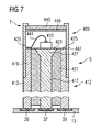
Eine vierte Ausführungsvariante des Stäbchens beziehungsweise Röhrchens 5 ist in
Der Stift 317 und die Hülse 313 sind aus einem elektrisch leitenden Material, beispielsweise Metall, hergestellt und gegeneinander elektrisch isoliert.The
Entweder die Innenseite der Hülse 313 oder die Außenseite des Stiftes 317 oder beide weisen eine elektrische Isolierung auf, sodass beide in körperlichem Kontakt miteinander stehen können, ohne dass ein elektrischer Kontakt entsteht. Die Hülse 313 weist zudem an ihrem distalen Ende einen Abschnitt 319 auf, in der sowohl ihr Außendurchmesser als auch ihr Innendurchmesser verringert ist. Am Übergang zwischen dem Abschnitt 319 mit verringertem Außen- und Innendurchmesser und dem Abschnitt ohne verringertem Außen- und Innendurchmesser ist eine ringförmige Anschlagfläche 321 gebildet, die als Anschlag für den Stift 317 dient.Either the inside of the
Am distalen Ende 344 des Stiftes 317 ist ein Kontaktflecken 323 vorhanden, in dem auf jeden Fall keine Isolierung vorhanden ist. Auf den Kontaktflecken 323 ist ein LED-Chip 315 aufgesetzt und mit dem Kontaktflecken 323 elektrisch leitend verbunden. Der LED-Chip 315 ist außerdem über einen Bonddraht 341 mit der Stirnfläche 342 desjenigen Abschnitts 319 der Hülse 313 verbunden, in dem die Hülse einen verringerten Innen- und Außendurchmesser aufweist. Zumindest diese Stirnfläche 342 weist keine elektrische Isolierung auf. Der Abschnitt 319 der Hülse 313 mit verringerten Innen- und Außendurchmesser bildet einen ringförmigen Kontakt, der um einen zentralen Kontakt herum, nämlich um den Kontaktflecken 323, angeordnet ist. Da er über das distale Ende 344 des Stiftes 317 vorsteht, begrenzt seine Innenwand 325 eine Vertiefung, die bis zum distalen Ende 344 des Stiftes 317 reicht. In diese Vertiefung ist ein Verguss 343 eingebracht. Diese Ausgestaltung bietet den Vorteil, dass der Verguss lediglich in die Vertiefung eingefüllt zu werden braucht.At the
Der Verguss kann in der vorliegenden Ausführungsvariante nach dem Aufbringen und Kontaktieren des LED-Chips in die Vertiefung eingefüllt und ausgehärtet werden. Statt durch Aushärten kann der Verguss auch durch eine transparente Abschlussscheibe in der Vertiefung gehalten werden, wenn der Bonddraht nicht die Stirnfläche 342 des Abschnitts 319, sondern eine Innenfläche dieses Abschnitts kontaktiert.The potting can be filled in the present embodiment after applying and contacting the LED chip in the well and cured. Instead of curing, the encapsulation can also be held in the depression by a transparent cover disk if the bonding wire does not contact the
In der vorliegenden Ausführungsvariante ist der distale hohle Abschnitt 309 durch eine distale Hülse 347 gebildet, deren Innendurchmesser dem Außendurchmesser der Hülse 313 des Zuleitungsabschnittes im Abschnitt mit reduziertem Innen- und Außendurchmesser entspricht. Dadurch kann die distale Hülse 347 auf den Zuleitungsabschnitt aufgesetzt und beispielsweise mit diesem verklebt werden.In the present embodiment, the distal
Das distale Ende der distalen Hülse 347 ist mit einer transparenten Scheibe verschlossen. Die Ausgestaltung der Scheibe entspricht der Ausgestaltung der mit Bezug auf
Eine sechste Variante des Stäbchens beziehungsweise Röhrchens 5 des Endoilluminators 1 ist in
Im Unterschied zur in
Das distale Ende des Zuleitungsabschnitts 412 weist einen Abschnitt 419 auf, in dem die Hülse 413 einen reduzierten Außendurchmesser aufweist. Eine distale Hülse 447 ist auf diesen Abschnitt 419 mit reduziertem Außendurchmesser aufgesetzt. Die Abmessungen der distalen Hülse 447 sind so gewählt, dass ihr Innendurchmesser dem Außendurchmesser des Abschnittes 419 entspricht und der Außendurchmesser der distalen Hülse 447 mit dem Außendurchmesser der Hülse 413 übereinstimmt, sodass eine möglichst glatte Außenfläche des Röhrchens beziehungsweise Stäbchens 5 entsteht.The distal end of the
Das distale Ende der distalen Hülse 447 ist mit einer Scheibe 445 verschlossen. Diese ist im sichtbaren Spektralbereich transparent und kann im ultravioletten Spektralbereich undurchlässig ausgestaltet sein. Zudem ist die Scheibe 445 an ihrer dem Hülseninneren zugewandten Seite mit einer Konverterbeschichtung 449 versehen. Diese Konverterbeschichtung kann entweder aus dem Konvertermaterial selbst bestehen oder das Konvertermaterial enthalten. Kombinationen aus wenigstens zwei Konvertermaterialien sind hierbei grundsätzlich auch möglich.The distal end of the
Obwohl in der vorliegenden Ausführungsvariante das Konvertermaterial in Form einer Beschichtung 449 auf die Innenseite der Scheibe 445 aufgebracht ist, kann es auch auf die Außenseite der Scheibe 445 aufgebracht oder beispielsweise als Dotierung in die Scheibe 445 eingebracht sein. Außerdem ist es auch in der in
Es sei an dieser Stelle darauf hingewiesen, dass nicht nur die mit Bezug auf
In den beiden letzten Ausführungsvarianten, in denen eine distale Hülse Verwendung findet, die auf den Zuleitungsabschnitt aufgesetzt ist, ist es nicht nötig, ein Leiterband durch ein langes Röhrchen zu führen. Auch braucht kein flexibles Leiterband im Bereich des LED-Chips zum Einsatz zu kommen. Da zudem die zylinderförmige Hülse des Zuleitungsabschnittes eine Fassung für die distale Hülse bildet, ist eine exakte Positionierung der distalen Hülse in Bezug auf den Zuleitungsabschnitt möglich. Dies ist insbesondere dann vorteilhaft, wenn die Innenseite der Scheibe der distalen Hülse mit einer Konverterbeschichtung versehen ist, da mit einfachen Mitteln sichergestellt werden kann, dass die Scheibeninnenseite mit keinem Element im Inneren des distalen hohlen Abschnitts in Kontakt gerät. Bei einem Kontakt könnte nämlich die Konverterbeschichtung Schaden nehmen. Falls das Konvertermaterial in einen Verguss eingebracht worden ist, anstatt auf die Scheibe aufgebracht zu sein, ist ein Kontakt zwischen dem Verguss und der Scheibe jedoch unkritisch.In the last two embodiments, in which a distal sleeve is used, which is placed on the lead portion, it is not necessary to guide a conductor band through a long tube. Also, no flexible conductor strip needs to be used in the area of the LED chip. In addition, since the cylindrical sleeve of the lead portion forms a socket for the distal sleeve, an exact positioning of the distal sleeve with respect to the lead portion is possible. This is particularly advantageous when the inside of the disc of the distal sleeve is provided with a converter coating, since it can be ensured by simple means that the disc inner side with no element in the interior of the distal hollow portion in contact. In fact, a contact could damage the converter coating. However, if the converter material has been placed in a potting, rather than being applied to the disk, contact between the potting and the disk is not critical.
In allen Ausführungsvarianten kann das Aufbringen des LED-Chips auf Kontaktflächen, Kontakte beziehungsweise Kontaktflecken durch sogenanntes Die-Bonden erfolgen. Das Die-Bonden ist eine sogenannte Chip-on-Board-Technologie, in der ein Chip ohne Gehäuse direkt auf ein Substrat, im vorliegenden Fall die Kontaktflächen, geklebt, gelötet, geglast, geschweißt (beispielsweise mittels Ultraschall) oder legiert wird, wobei eine elektrisch leitender Kotakt zwischen dem Substrat und dem Chip hergestellt wird.In all embodiments, the application of the LED chip on contact surfaces, contacts or contact pads can be done by so-called die-bonding. The die bonding is a so-called chip-on-board technology in which a chip without housing directly to a substrate, in the present case, the contact surfaces, glued, soldered, cast, welded (for example by means of ultrasound) or alloyed, wherein a electrically conductive Kotakt between the substrate and the chip is produced.
Die Erfindung stellt medizinische Beleuchtungseinheiten und insbesondere Endoilluminatoren bereit, die auch bei Verwendung von Röhrchen beziehungsweise Stäbchen mit sehr geringem Außendurchmesser eine Anregungslichtquelle am distalen Ende aufweisen können. Dadurch entfällt das oft schwierige Einkoppeln des Lichtes in einen Lichtleiter.The invention provides medical lighting units and in particular endoilluminators, which can also have an excitation light source at the distal end even when using tubes or rods with a very small outside diameter. This eliminates the often difficult coupling of the light in a light guide.
Claims (15)
gekennzeichnet durch einen zwischen dem LED-Chip (15, 115, 116, 215, 315, 415) und dem distalen Ende (7) des stabförmigen oder röhrenförmigen Körpers oder am distalen Ende des stabförmigen oder röhrenförmigen Körpers (5) angeordneten Konverterleuchtstoff, dessen Konvertereigenschaften hinsichtlich des von dem LED-Chip (15, 115, 116, 215, 315, 415) emittierten Lichts derart ausgewählt ist, dass er das von dem LED-Chip (15, 115, 116, 215, 315, 415) emittierte Licht in Licht mit einer gewünschten Wellenlängenverteilung konvertiert.
characterized by a converter phosphor arranged between the LED chip (15, 115, 116, 215, 315, 415) and the distal end (7) of the rod-shaped or tubular body or at the distal end of the rod-shaped or tubular body (5), the converter properties thereof with respect to the light emitted from the LED chip (15, 115, 116, 215, 315, 415) is selected to receive the light emitted from the LED chip (15, 115, 116, 215, 315, 415) Converted light with a desired wavelength distribution.
gekennzeichnet, dass
marked that
Applications Claiming Priority (1)
| Application Number | Priority Date | Filing Date | Title |
|---|---|---|---|
| DE102007055003A DE102007055003A1 (en) | 2007-11-14 | 2007-11-14 | Medical lighting unit |
Publications (2)
| Publication Number | Publication Date |
|---|---|
| EP2060226A1 true EP2060226A1 (en) | 2009-05-20 |
| EP2060226B1 EP2060226B1 (en) | 2017-01-04 |
Family
ID=40274197
Family Applications (1)
| Application Number | Title | Priority Date | Filing Date |
|---|---|---|---|
| EP08075879.0A Active EP2060226B1 (en) | 2007-11-14 | 2008-11-13 | Endoilluminator |
Country Status (4)
| Country | Link |
|---|---|
| US (1) | US7922378B2 (en) |
| EP (1) | EP2060226B1 (en) |
| JP (1) | JP2009136673A (en) |
| DE (1) | DE102007055003A1 (en) |
Cited By (1)
| Publication number | Priority date | Publication date | Assignee | Title |
|---|---|---|---|---|
| DE102018202241A1 (en) * | 2018-02-14 | 2019-08-14 | Richard Wolf Gmbh | Ultra-miniaturized light-emitting unit for a medical-endoscopic instrument |
Families Citing this family (14)
| Publication number | Priority date | Publication date | Assignee | Title |
|---|---|---|---|---|
| JP2009226156A (en) * | 2008-03-25 | 2009-10-08 | Oita Univ | Intraocular lighting probe |
| KR101603257B1 (en) * | 2009-01-21 | 2016-03-14 | 알콘 리서치, 리미티드 | Ophthalmic endoillumination using fiber generated light |
| DE102009024941A1 (en) * | 2009-06-09 | 2010-12-23 | Carl Zeiss Surgical Gmbh | Lighting device and medical-optical observation device |
| CN102437149A (en) * | 2010-09-29 | 2012-05-02 | 比亚迪股份有限公司 | LED (Light-Emitting Diode) light-emitting device and manufacturing method thereof |
| DE102013201808A1 (en) * | 2013-02-05 | 2014-08-07 | Richard Wolf Gmbh | LED lighting module |
| USD938095S1 (en) | 2013-04-01 | 2021-12-07 | Pathy Medical, Llc | Lighting device |
| JP6379178B2 (en) | 2013-04-01 | 2018-08-22 | ビノド ヴイ パシー | Lighting device |
| US9636112B2 (en) * | 2013-08-16 | 2017-05-02 | Covidien Lp | Chip assembly for reusable surgical instruments |
| DE112017003184T5 (en) * | 2016-06-27 | 2019-03-07 | Olympus Corporation | Endoscope and manufacturing process for an endoscope |
| DE102016213069A1 (en) * | 2016-07-18 | 2018-01-18 | Osram Gmbh | LEDS ARRANGEMENT |
| US20200268470A1 (en) * | 2017-04-26 | 2020-08-27 | Pharmpur Gmbh | Device for lighting the intraocular cavity |
| AU2020418818B2 (en) * | 2019-12-30 | 2023-11-16 | Boston Scientific Scimed, Inc. | Devices for locating a body lumen |
| US20220047260A1 (en) * | 2020-08-12 | 2022-02-17 | Covidien Lp | Chipped trocar assembly for circular stapling instruments |
| CN114903685A (en) * | 2021-02-07 | 2022-08-16 | 程秀著 | LED lacrimal probe |
Citations (6)
| Publication number | Priority date | Publication date | Assignee | Title |
|---|---|---|---|---|
| US6028694A (en) * | 1997-05-22 | 2000-02-22 | Schmidt; Gregory W. | Illumination device using pulse width modulation of a LED |
| US20040090796A1 (en) | 2002-07-03 | 2004-05-13 | Steen Mark E. | Light source for ophthalmic use |
| US20050154262A1 (en) * | 2003-04-01 | 2005-07-14 | Banik Michael S. | Imaging system for video endoscope |
| US20050194876A1 (en) * | 2004-03-05 | 2005-09-08 | Junichi Shimada | Lighting apparatus, filter apparatus, and image display |
| US20060069314A1 (en) * | 2004-09-24 | 2006-03-30 | Mina Farr | Solid state illumination for endoscopy |
| EP1719482A1 (en) | 2005-04-29 | 2006-11-08 | Alcon, Inc | Multi-fiber variable intensity wide-angle illuminator |
Family Cites Families (15)
| Publication number | Priority date | Publication date | Assignee | Title |
|---|---|---|---|---|
| US5445608A (en) * | 1993-08-16 | 1995-08-29 | James C. Chen | Method and apparatus for providing light-activated therapy |
| US6068383A (en) * | 1998-03-02 | 2000-05-30 | Robertson; Roger | Phosphorous fluorescent light assembly excited by light emitting diodes |
| US6504301B1 (en) * | 1999-09-03 | 2003-01-07 | Lumileds Lighting, U.S., Llc | Non-incandescent lightbulb package using light emitting diodes |
| US6466135B1 (en) * | 2000-05-15 | 2002-10-15 | General Electric Company | Phosphors for down converting ultraviolet light of LEDs to blue-green light |
| US6577073B2 (en) * | 2000-05-31 | 2003-06-10 | Matsushita Electric Industrial Co., Ltd. | Led lamp |
| DE10142009B4 (en) * | 2001-08-28 | 2010-04-22 | Osram Opto Semiconductors Gmbh | LED light source with a conversion agent and with a UV absorbing layer |
| US6711426B2 (en) * | 2002-04-09 | 2004-03-23 | Spectros Corporation | Spectroscopy illuminator with improved delivery efficiency for high optical density and reduced thermal load |
| TWI226138B (en) * | 2003-01-03 | 2005-01-01 | Super Nova Optoelectronics Cor | GaN-based LED vertical device structure and the manufacturing method thereof |
| US20040159900A1 (en) * | 2003-01-27 | 2004-08-19 | 3M Innovative Properties Company | Phosphor based light sources having front illumination |
| US6903380B2 (en) * | 2003-04-11 | 2005-06-07 | Weldon Technologies, Inc. | High power light emitting diode |
| US7005679B2 (en) * | 2003-05-01 | 2006-02-28 | Cree, Inc. | Multiple component solid state white light |
| WO2006102846A1 (en) | 2005-04-01 | 2006-10-05 | Yi Li | High efficient light coupling of solid-state light source into etendue maintained optical waveguide/fiber |
| US20060266366A1 (en) * | 2005-05-25 | 2006-11-30 | Ross Tsukashima | Illumination means for catheter placement |
| US7270439B2 (en) * | 2005-06-13 | 2007-09-18 | Horrell Robin S | Compact lighting system attachable to a surgical tool and method of use thereof |
| KR100706952B1 (en) * | 2005-07-22 | 2007-04-12 | 삼성전기주식회사 | VERTICALLY STRUCTURED GaN TYPE LED DEVICE AND METHOD OF MANUFACTURING THE SAME |
-
2007
- 2007-11-14 DE DE102007055003A patent/DE102007055003A1/en not_active Ceased
-
2008
- 2008-11-13 EP EP08075879.0A patent/EP2060226B1/en active Active
- 2008-11-14 US US12/270,923 patent/US7922378B2/en active Active
- 2008-11-14 JP JP2008291749A patent/JP2009136673A/en active Pending
Patent Citations (6)
| Publication number | Priority date | Publication date | Assignee | Title |
|---|---|---|---|---|
| US6028694A (en) * | 1997-05-22 | 2000-02-22 | Schmidt; Gregory W. | Illumination device using pulse width modulation of a LED |
| US20040090796A1 (en) | 2002-07-03 | 2004-05-13 | Steen Mark E. | Light source for ophthalmic use |
| US20050154262A1 (en) * | 2003-04-01 | 2005-07-14 | Banik Michael S. | Imaging system for video endoscope |
| US20050194876A1 (en) * | 2004-03-05 | 2005-09-08 | Junichi Shimada | Lighting apparatus, filter apparatus, and image display |
| US20060069314A1 (en) * | 2004-09-24 | 2006-03-30 | Mina Farr | Solid state illumination for endoscopy |
| EP1719482A1 (en) | 2005-04-29 | 2006-11-08 | Alcon, Inc | Multi-fiber variable intensity wide-angle illuminator |
Cited By (1)
| Publication number | Priority date | Publication date | Assignee | Title |
|---|---|---|---|---|
| DE102018202241A1 (en) * | 2018-02-14 | 2019-08-14 | Richard Wolf Gmbh | Ultra-miniaturized light-emitting unit for a medical-endoscopic instrument |
Also Published As
| Publication number | Publication date |
|---|---|
| US7922378B2 (en) | 2011-04-12 |
| EP2060226B1 (en) | 2017-01-04 |
| JP2009136673A (en) | 2009-06-25 |
| DE102007055003A1 (en) | 2009-05-20 |
| US20090129051A1 (en) | 2009-05-21 |
Similar Documents
| Publication | Publication Date | Title |
|---|---|---|
| EP2060226B1 (en) | Endoilluminator | |
| EP2953519B1 (en) | Led lighting module | |
| EP1750571B1 (en) | Laryngoscope | |
| DE102006001290B3 (en) | Housing-enclosure for electronic housing, especially sensor housing, has contact elements and lighting element accommodated in partly transparent contact-display-module | |
| EP2254499B1 (en) | Light source for a dental device | |
| DE102004061551A1 (en) | Dental curing device with a heat sink for dissipating heat | |
| EP1870022A2 (en) | Medical handle with a lighting device and method of manufacturing | |
| DE102008011153A1 (en) | Arrangement with at least two light-emitting semiconductor components and method for producing an arrangement with at least two light-emitting semiconductor components | |
| DE112016006871T5 (en) | A cable connecting substrate, image pickup device, endoscope and method of manufacturing an image pickup device | |
| EP1843080A2 (en) | Semi-conductor radiation source | |
| DE102009007650A1 (en) | Illuminant with heat spreading by heat conduction coating and adaptation to the power supply network and manufacturing method thereof | |
| DE102010044786A1 (en) | Rigid video endoscope with insulating conductor carrier | |
| EP2955740B1 (en) | Lamp and adapter for a lamp | |
| DE102017217340A1 (en) | LED EMITTER AND METHOD FOR THE PRODUCTION THEREOF | |
| DE3706934A1 (en) | Dental hand-held ultrasound instrument | |
| EP1795225A1 (en) | Housing for a medical implant | |
| DE102015103331B4 (en) | Hermetically sealed LED luminaire, method for producing a hermetically sealed LED luminaire and medical instrument comprising a hermetically sealed LED luminaire | |
| EP3064166B1 (en) | Hermetically sealed led light, and method for manufacturing a hermetically sealed led light | |
| DE112016006804T5 (en) | Cable connection structure, imaging device and endoscope | |
| EP3341975B1 (en) | Method for producing light-emitting semiconductor components | |
| DE102011076122A1 (en) | Steam-sterilizable light source for medical device i.e. endoscope, for minimum-invasive treatment in body, has lamp whose connection part is connected with housing such that operating temperature of lamp is derivable to side of housing | |
| DE102017223191A1 (en) | Dental hand instrument with a vibration exciter and a treatment tool that can be coupled therewith | |
| EP2305163B1 (en) | Lighting device for a dental handpiece | |
| DE102018105733A1 (en) | Device for exposing and keeping open a surgical area | |
| EP3210521A1 (en) | Endoscopic shaft instrument |
Legal Events
| Date | Code | Title | Description |
|---|---|---|---|
| PUAI | Public reference made under article 153(3) epc to a published international application that has entered the european phase |
Free format text: ORIGINAL CODE: 0009012 |
|
| AK | Designated contracting states |
Kind code of ref document: A1 Designated state(s): AT BE BG CH CY CZ DE DK EE ES FI FR GB GR HR HU IE IS IT LI LT LU LV MC MT NL NO PL PT RO SE SI SK TR |
|
| AX | Request for extension of the european patent |
Extension state: AL BA MK RS |
|
| 17P | Request for examination filed |
Effective date: 20091103 |
|
| 17Q | First examination report despatched |
Effective date: 20091208 |
|
| AKX | Designation fees paid |
Designated state(s): DE ES FR GB IT |
|
| RAP1 | Party data changed (applicant data changed or rights of an application transferred) |
Owner name: CARL ZEISS MEDITEC AG |
|
| GRAJ | Information related to disapproval of communication of intention to grant by the applicant or resumption of examination proceedings by the epo deleted |
Free format text: ORIGINAL CODE: EPIDOSDIGR1 |
|
| GRAP | Despatch of communication of intention to grant a patent |
Free format text: ORIGINAL CODE: EPIDOSNIGR1 |
|
| RIC1 | Information provided on ipc code assigned before grant |
Ipc: H01L 33/50 20100101ALI20160621BHEP Ipc: A61B 1/06 20060101AFI20160621BHEP |
|
| INTG | Intention to grant announced |
Effective date: 20160713 |
|
| GRAS | Grant fee paid |
Free format text: ORIGINAL CODE: EPIDOSNIGR3 |
|
| GRAA | (expected) grant |
Free format text: ORIGINAL CODE: 0009210 |
|
| AK | Designated contracting states |
Kind code of ref document: B1 Designated state(s): DE ES FR GB IT |
|
| REG | Reference to a national code |
Ref country code: GB Ref legal event code: FG4D Free format text: NOT ENGLISH |
|
| REG | Reference to a national code |
Ref country code: DE Ref legal event code: R096 Ref document number: 502008014926 Country of ref document: DE |
|
| PG25 | Lapsed in a contracting state [announced via postgrant information from national office to epo] |
Ref country code: ES Free format text: LAPSE BECAUSE OF FAILURE TO SUBMIT A TRANSLATION OF THE DESCRIPTION OR TO PAY THE FEE WITHIN THE PRESCRIBED TIME-LIMIT Effective date: 20170104 |
|
| REG | Reference to a national code |
Ref country code: DE Ref legal event code: R097 Ref document number: 502008014926 Country of ref document: DE |
|
| PG25 | Lapsed in a contracting state [announced via postgrant information from national office to epo] |
Ref country code: IT Free format text: LAPSE BECAUSE OF FAILURE TO SUBMIT A TRANSLATION OF THE DESCRIPTION OR TO PAY THE FEE WITHIN THE PRESCRIBED TIME-LIMIT Effective date: 20170104 |
|
| PLBE | No opposition filed within time limit |
Free format text: ORIGINAL CODE: 0009261 |
|
| STAA | Information on the status of an ep patent application or granted ep patent |
Free format text: STATUS: NO OPPOSITION FILED WITHIN TIME LIMIT |
|
| REG | Reference to a national code |
Ref country code: FR Ref legal event code: PLFP Year of fee payment: 10 |
|
| 26N | No opposition filed |
Effective date: 20171005 |
|
| P01 | Opt-out of the competence of the unified patent court (upc) registered |
Effective date: 20230530 |
|
| PGFP | Annual fee paid to national office [announced via postgrant information from national office to epo] |
Ref country code: GB Payment date: 20231123 Year of fee payment: 16 |
|
| PGFP | Annual fee paid to national office [announced via postgrant information from national office to epo] |
Ref country code: FR Payment date: 20231120 Year of fee payment: 16 Ref country code: DE Payment date: 20231121 Year of fee payment: 16 |