EP2059369B1 - Percussion device, drilling machine including such a percussion device and method for controlling such a percussion device - Google Patents
Percussion device, drilling machine including such a percussion device and method for controlling such a percussion device Download PDFInfo
- Publication number
- EP2059369B1 EP2059369B1 EP20070835043 EP07835043A EP2059369B1 EP 2059369 B1 EP2059369 B1 EP 2059369B1 EP 20070835043 EP20070835043 EP 20070835043 EP 07835043 A EP07835043 A EP 07835043A EP 2059369 B1 EP2059369 B1 EP 2059369B1
- Authority
- EP
- European Patent Office
- Prior art keywords
- control
- valve
- percussion device
- control channels
- valve element
- Prior art date
- Legal status (The legal status is an assumption and is not a legal conclusion. Google has not performed a legal analysis and makes no representation as to the accuracy of the status listed.)
- Active
Links
- 238000009527 percussion Methods 0.000 title claims description 35
- 238000005553 drilling Methods 0.000 title claims description 25
- 238000000034 method Methods 0.000 title claims description 19
- 239000011435 rock Substances 0.000 claims description 9
- 239000012530 fluid Substances 0.000 claims description 8
- 230000035939 shock Effects 0.000 claims description 8
- 230000008569 process Effects 0.000 claims description 7
- 238000013016 damping Methods 0.000 claims description 6
- 230000000903 blocking effect Effects 0.000 claims description 5
- 230000004044 response Effects 0.000 claims description 5
- 239000000463 material Substances 0.000 claims 1
- 230000008901 benefit Effects 0.000 description 3
- 230000009471 action Effects 0.000 description 2
- 238000004891 communication Methods 0.000 description 2
- 230000000694 effects Effects 0.000 description 2
- 230000009467 reduction Effects 0.000 description 2
- 230000011514 reflex Effects 0.000 description 2
- 229910000831 Steel Inorganic materials 0.000 description 1
- 230000005540 biological transmission Effects 0.000 description 1
- 230000008859 change Effects 0.000 description 1
- 238000010586 diagram Methods 0.000 description 1
- 230000006872 improvement Effects 0.000 description 1
- 230000000977 initiatory effect Effects 0.000 description 1
- 238000005259 measurement Methods 0.000 description 1
- 230000000284 resting effect Effects 0.000 description 1
- 238000007789 sealing Methods 0.000 description 1
- 239000010959 steel Substances 0.000 description 1
Images


Classifications
-
- B—PERFORMING OPERATIONS; TRANSPORTING
- B25—HAND TOOLS; PORTABLE POWER-DRIVEN TOOLS; MANIPULATORS
- B25D—PERCUSSIVE TOOLS
- B25D9/00—Portable percussive tools with fluid-pressure drive, i.e. driven directly by fluids, e.g. having several percussive tool bits operated simultaneously
- B25D9/14—Control devices for the reciprocating piston
- B25D9/26—Control devices for adjusting the stroke of the piston or the force or frequency of impact thereof
-
- B—PERFORMING OPERATIONS; TRANSPORTING
- B25—HAND TOOLS; PORTABLE POWER-DRIVEN TOOLS; MANIPULATORS
- B25D—PERCUSSIVE TOOLS
- B25D9/00—Portable percussive tools with fluid-pressure drive, i.e. driven directly by fluids, e.g. having several percussive tool bits operated simultaneously
- B25D9/14—Control devices for the reciprocating piston
- B25D9/16—Valve arrangements therefor
-
- E—FIXED CONSTRUCTIONS
- E21—EARTH OR ROCK DRILLING; MINING
- E21B—EARTH OR ROCK DRILLING; OBTAINING OIL, GAS, WATER, SOLUBLE OR MELTABLE MATERIALS OR A SLURRY OF MINERALS FROM WELLS
- E21B44/00—Automatic control systems specially adapted for drilling operations, i.e. self-operating systems which function to carry out or modify a drilling operation without intervention of a human operator, e.g. computer-controlled drilling systems; Systems specially adapted for monitoring a plurality of drilling variables or conditions
- E21B44/02—Automatic control of the tool feed
- E21B44/08—Automatic control of the tool feed in response to the amplitude of the movement of the percussion tool, e.g. jump or recoil
-
- E—FIXED CONSTRUCTIONS
- E21—EARTH OR ROCK DRILLING; MINING
- E21B—EARTH OR ROCK DRILLING; OBTAINING OIL, GAS, WATER, SOLUBLE OR MELTABLE MATERIALS OR A SLURRY OF MINERALS FROM WELLS
- E21B6/00—Drives for drilling with combined rotary and percussive action
- E21B6/06—Drives for drilling with combined rotary and percussive action the rotation being intermittent, e.g. obtained by ratchet device
- E21B6/08—Separate drives for percussion and rotation
-
- E—FIXED CONSTRUCTIONS
- E21—EARTH OR ROCK DRILLING; MINING
- E21B—EARTH OR ROCK DRILLING; OBTAINING OIL, GAS, WATER, SOLUBLE OR MELTABLE MATERIALS OR A SLURRY OF MINERALS FROM WELLS
- E21B7/00—Special methods or apparatus for drilling
- E21B7/02—Drilling rigs characterised by means for land transport with their own drive, e.g. skid mounting or wheel mounting
- E21B7/025—Rock drills, i.e. jumbo drills
-
- B—PERFORMING OPERATIONS; TRANSPORTING
- B25—HAND TOOLS; PORTABLE POWER-DRIVEN TOOLS; MANIPULATORS
- B25D—PERCUSSIVE TOOLS
- B25D2250/00—General details of portable percussive tools; Components used in portable percussive tools
- B25D2250/005—Adjustable tool components; Adjustable parameters
-
- Y—GENERAL TAGGING OF NEW TECHNOLOGICAL DEVELOPMENTS; GENERAL TAGGING OF CROSS-SECTIONAL TECHNOLOGIES SPANNING OVER SEVERAL SECTIONS OF THE IPC; TECHNICAL SUBJECTS COVERED BY FORMER USPC CROSS-REFERENCE ART COLLECTIONS [XRACs] AND DIGESTS
- Y10—TECHNICAL SUBJECTS COVERED BY FORMER USPC
- Y10T—TECHNICAL SUBJECTS COVERED BY FORMER US CLASSIFICATION
- Y10T137/00—Fluid handling
- Y10T137/8593—Systems
- Y10T137/86493—Multi-way valve unit
- Y10T137/86574—Supply and exhaust
- Y10T137/86582—Pilot-actuated
-
- Y—GENERAL TAGGING OF NEW TECHNOLOGICAL DEVELOPMENTS; GENERAL TAGGING OF CROSS-SECTIONAL TECHNOLOGIES SPANNING OVER SEVERAL SECTIONS OF THE IPC; TECHNICAL SUBJECTS COVERED BY FORMER USPC CROSS-REFERENCE ART COLLECTIONS [XRACs] AND DIGESTS
- Y10—TECHNICAL SUBJECTS COVERED BY FORMER USPC
- Y10T—TECHNICAL SUBJECTS COVERED BY FORMER US CLASSIFICATION
- Y10T137/00—Fluid handling
- Y10T137/8593—Systems
- Y10T137/86493—Multi-way valve unit
- Y10T137/86574—Supply and exhaust
- Y10T137/86622—Motor-operated
- Y10T137/8663—Fluid motor
Definitions
- the invention concerns a percussion device according to the preamble of claim 1 and a method for controlling a percussion device according to the preamble of claim 13.
- a percussion device and such a method are known from EP 0080 446-A2 .
- the invention also concerns a rock drilling machine including such a percussion device.
- EP-0 080 446 (Atlas Copco AB) discloses a rock drilling machine, wherein the feeding force is transmitted from the housing to the drill string or the drill string adapter over a damper.
- the damper yields from the reflected compressive shock waves and the yield is detected and used to control a control pin which adjust the stroke length for the percussive piston such that the reflective shock wave energy is minimized.
- control pin is an adjustment means which adjusts in what axial position of the percussive piston a pressure signal is transmitted to a to-and-fro moveable valve body, wherein means are arranged in order to control the control pin as a response to the pressure signal such that the operation of the percussion device is modified for reduction of reflected shock wave.
- control pin is controlled after analysis of a drilling parameter in connection to the drill string.
- the known drilling machine functions well but is gives limited possibilities to easily control the axial turning positions of the percussive piston.
- the setting channel (control channel) for high pressure can be moved reward, i.e. in the direction away from the drill shank, which results in longer strike length and more power in each strike. Given the same pressure it takes longer time to accelerate the piston when the strike length is longer, which results in drilling with a lower frequency.
- the percussion device can be controlled with simple means in the direction of optimizing drilling and reduction of shock wave reflexes, which the drilling process does not benefit from.
- the invention makes it possible to take account of this phenomenon and that a percussive energy is controlled in order to be better adapted to the state of wear of the drill bit. These gives the possibility to achieve increased drilling rate with the same percussive effect, reduced strain in the drill steel, less reflexes from the rock, which in turn can result in that a smaller damping unit will be necessary.
- a drilling machine can be easily adapted to varied drill bit wear, rock strength and drill bit size.
- the drilling machine can hereby be set in advance for certain of the parameters which are known or be controlled during drilling after need and sensed parameters.
- control is possible as a response to a parameter describing the drilling process, such as for example drilling rate or pressure in a damping chamber or as a result of shock wave amplitude, measured through shock wave measurements.
- a parameter describing the drilling process such as for example drilling rate or pressure in a damping chamber or as a result of shock wave amplitude, measured through shock wave measurements.
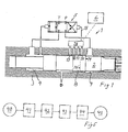
- Fig. 1 shows a part of a rock drilling machine 1 including a percussion device with a percussion piston 2.
- a valve for switching pressure medium for driving the percussive piston is indicated with 5.
- a central positioning unit 6 and a rotation unit, a damping unit etc. which are not shown on Fig. 1 .
- the percussive piston 2 is reciprocally moveable inside the machine housing 3.
- a percussive piston land 8 there are, in the area of a percussive piston land 8, a number of control channels 10 - 13 which are arranged to co-operate, with their channel openings, with a first edge 14 of the percussive piston land 8.
- An interrupted line indicates at 14' a position of the first edge 14 when the percussive piston has retracted after a strike so that the opening to the control channel 10 is uncovered.
- a chamber 4 that can be pressurized receives in a per se known manner a drive face on the percussive piston in the form of drive flank of a percussive piston land.
- valve means 16 For chosen communication between the different control channels and a signal conduit 15, which leads to the valve 5 for switching the movement direction of the percussion device, there is arranged a valve means 16, the function of which is explained below.
- the percussive piston 2 is actuated by high fluid pressure in the chamber 4 towards a striking position in order to initiate a strike in the direction to the right, as seen in the Figure, in a per se known manner, against a drill shank.
- the return chamber 9 which receives a flank of a percussive piston land having a surface being smaller than the surface of the flank in the chamber 4, there prevails during operation, in a manner known per se, during the return drive of the percussive piston, the high pressure.
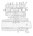
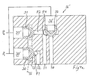
- Fig. 2 shows the valve means 16 according to a first embodiment, wherein two concentric valve elements control how the control channels 10 -14 communicate with the signal conduit 15.
- the valve means 16 includes a first valve element 17 and, arranged concentrically inside this, a second valve element 18. Both valve elements have cylindrical general configuration and are moveable axially as desired.
- a valve housing 19 which receives the valve elements, exhibits at its right flank end a constant pressure chamber 20, inside which prevails a pressure P d , permanently acting on both valve elements, which thus from this pressure are pressed to the left as seen in Fig. 2 .
- the first valve element 17 has on its opposite, left, side a first control chamber 21, which at choice is fed with a first pressure P 1 which is of such a magnitude that the pressurizing of the first control chamber 21 displaces the first valve element from the shown position to a position to the right against the action of the pressure P d .
- a second control chamber 22 is arranged, at choice, to be pressurized by a second pressure P 2 , which is able to press the second valve element 18 to the right against the action of the pressure P d . In this embodiment this means resting against an inward shoulder 23 on the first valve element 17.
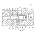
- valve means 16 is in Fig. 3a shown in a position when the "uppermost" situated control channel 13 alone is in connection with the signal conduit 15, which it is permanently through a permanent communication.
- the other control channels 10 - 12 are blocked.
- connection means that channel portions of a connection between the control channel and the respective control channels is open for the possibility of fluid transmission. It is, however, not excluded that a control channel having a channel portion open can be included in a connection which is blocked as seen totally along its extension by the effect of a second valve element blocking a second channel portion.
- Fig. 3a the first valve element 17 is shown in its first position, wherein first portions F1 of connections between a first subset 10 and 12, of the control channels and the control valve 5 are blocked by this first valve element 17. No (or a lower) control pressure prevails in each one of the control chambers 21 and 22.
- the second valve element 18 is shown in its first position, wherein a second portion F2 of a connection between a second subset 10 (/11) of the control channels and the control valve 5 is blocked.
- the first valve element is constructed such that a portion F3 of connection between the control valve and a control channel 11 from the second subset is open.
- the position of the second valve blocks according to the above the further connection with a control valve 5.
- the control channel 13 is in connection with the control valve 5, whereas the second control channels 10, 11 and 12 are blocked along their connections.
- control channels 10 - 13 are axially separated with the same spacing, and the distance between the channel portions 24 and 25 in the first valve element (approximately) corresponds to the distance 2xL, wherein, in this embodiment, L is the distance between centres of two adjacent control channels. It should be noted that a differently constructed embodiment can be designed with a variation of distance between the different openings in order to achieve a desired characteristic of the percussion device.
- Reference numerals 24' and 25' concern surrounding turned out grooves in the cylindrical outer wall of the first valve element in per se known manner for valve bodies of similar kind.
- the turned out groove 25' has an axial extension which (about) corresponds to L for reasons that will appear below.
- the second valve element 18 exhibits two piston portions 27 and 28 sealing against an inner cylindrical space in the first element 17, and the intermediate, turned out groove 26, has a width exceeding 2xL. It should be observed that channelling from the control channels can be arranged such that mutual distances between openings in the valve means 17 deviate from distance between the openings in the percussive piston cylinder.
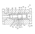
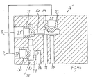
- Fig. 3b prevails a control pressure P 1 in the control chamber 21 but no (or a lower) control pressure in the control chamber 22.
- the first valve element 17 is switched to a second position, wherein the channel portions 24 and 25 are in open connection with the control channels 10 and 12 respectively.
- the control channel 11 is, however, locked and the turned out groove 25' transmits fluid connection through open connection with each one of the control channels 12 and 13.
- the portions F1 are open.
- the second valve element 18 is still in its first position and blocks through its piston portion 27 the channel portion 24.
- the second portion F2 is blocked.
- both control channels 12 and 13, but not the control channels 10 and 11 have fluid connection with the signal conduit 15.
- Fig. 3c there prevails no (or a lower) control pressure inside the control chamber 21, but the control pressure P 2 prevails in the control chamber 22.
- the first valve element 17 is in the first position, the same as in Fig. 3a , whereas the second valve element 18 is in a second position, with its axial end, positioned towards the not shown drill shank, lying against the inwardly directed shoulder 23 in the first valve element.
- Said second portion F2 is open.
- a channel 26 being formed by a turned out cavity in the second valve element 18 and the inner surface of the first valve element 17 together with the upper parts of the channel portions 24 and 25 constitutes an open connection over said second portion F2. The result of this is at the control channel 11 over the channel portion 24, the turned out cavity 26 and the channel portion 25 has fluid connection with the control channel 13 and thereby with the signal conduit 15.
- the control channel 10 is blocked along its extension.
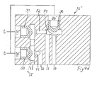
- control pressure P 1 prevails in the control chamber 21 and the control pressure P 2 in the control chamber 22.
- the first valve element 17 is in its second position, the same as in Fig. 3b , whereas the second valve element 18 is also in its second position lying against the inward directed shoulder 23.
- the result of this is that the control channel 10 has fluid connection with the control channel 13 and thereby with the signal conduit 15 over the channel portions 24 and 25 and the turned out cavities 26 and 25'.
- the portions F1 and F2 are open.
- the turned out cavity 26 in the second valve element 18 and the inner surface of the first valve element 17 together with the upper parts of the valve portions 24 and 25 constitute, as is indicated above, an open connection.
- Figs. 4a - 4d show an example of a valve means 16', wherein three valve bodies 30 - 32 acting against respective valve seats are arranged to control opening and blocking respectively of one control channel each. Also in this example only two control pressures are needed for its actuation.
- both valve elements 30 and 32 With a first control pressure P 1 in the control chambers 30' and 32', both valve elements 30 and 32 are in their first positions, wherein the connection portion F1 (through the valve element 30) is blocked and thereby the connection between control channels 10 and 12 as well as the control valve.
- a second control pressure P 2 in the control chamber 31' the valve element 31 in its first position, whereby the connection portion F2 between the respective control channels and the control valve is blocked and thereby the control channel 11 (and also the control channel 10), which is shown in Fig. 4a .
- connection portion F1 is open, but because the second control pressure P 2 prevails in the control chamber 31, the connection portion F2 is blocked and thereby the connection between the control valve and the control channel 11 (and also the control channel 10), which is shown in Fig. 4b .
- the control chamber 10 as well as 12 are blocked, and by a lower pressure P 0 prevailing in the control chamber 31', it is provided an open connection with the control channel 11 which is shown in Fig. 4c .
- the connection portion F2 is open.
- connection portions F1 and F2 are open. Further, a connection portion F4 between the upper part of the control channel 10 and the portion F2 is open. Thus is provided an open connection with all control channels 10 - 12, which is shown in Fig. 4d .
- the longest strike length of the percussive piston is achieved if all control channels 10, 11 and 12 are blocked such that only the control channel 13 communicates with the signal conduit 15, whereby the valve 5 is switched at a late stage of the return movement of the percussive piston.
- Shortest strike length is achieved if the control channel 10 communicates with the signal conduit 15, whereby the valve 5 is switched at an early stage of the return movement of the percussive piston.
- Fig. 5 is indicated a method sequence for obtaining a strike in a percussive device, wherein:
- the invention can be modified further within the scope of the following claims.
- the percussion device can work according to the different principles besides what is shown on Fig. 1 , with permanently applied pressure in the striking direction of the percussive piston and alternating pressurizing for the return stroke or vice versa.
- the invention can be applied for controlling the upper turning position of the percussive piston as well as its lower turning position. It can also be applied in applications without rotational unit and damper, for example on so called breakers.
Landscapes
- Engineering & Computer Science (AREA)
- Geology (AREA)
- Life Sciences & Earth Sciences (AREA)
- Mining & Mineral Resources (AREA)
- Fluid Mechanics (AREA)
- Physics & Mathematics (AREA)
- Geochemistry & Mineralogy (AREA)
- Environmental & Geological Engineering (AREA)
- General Life Sciences & Earth Sciences (AREA)
- Mechanical Engineering (AREA)
- Automation & Control Theory (AREA)
- Earth Drilling (AREA)
- Percussive Tools And Related Accessories (AREA)
- Drilling And Exploitation, And Mining Machines And Methods (AREA)
Applications Claiming Priority (2)
| Application Number | Priority Date | Filing Date | Title |
|---|---|---|---|
| SE0601879A SE530524C2 (sv) | 2006-09-13 | 2006-09-13 | Slagverk, bergborrmaskin inkluderande ett dylikt slagverk och förfarande för styrning av ett slagverk |
| PCT/SE2007/000794 WO2008033075A1 (en) | 2006-09-13 | 2007-09-12 | Percussion device, drilling machine including such a percussion device and method for controlling such a percussion device |
Publications (3)
| Publication Number | Publication Date |
|---|---|
| EP2059369A1 EP2059369A1 (en) | 2009-05-20 |
| EP2059369A4 EP2059369A4 (en) | 2013-04-24 |
| EP2059369B1 true EP2059369B1 (en) | 2014-07-23 |
Family
ID=39184032
Family Applications (1)
| Application Number | Title | Priority Date | Filing Date |
|---|---|---|---|
| EP20070835043 Active EP2059369B1 (en) | 2006-09-13 | 2007-09-12 | Percussion device, drilling machine including such a percussion device and method for controlling such a percussion device |
Country Status (11)
| Country | Link |
|---|---|
| US (1) | US8069928B2 (no) |
| EP (1) | EP2059369B1 (no) |
| JP (1) | JP5503967B2 (no) |
| CN (1) | CN101500762B (no) |
| AU (1) | AU2007295144B2 (no) |
| CA (1) | CA2661228C (no) |
| ES (1) | ES2513821T3 (no) |
| NO (1) | NO329141B1 (no) |
| SE (1) | SE530524C2 (no) |
| WO (1) | WO2008033075A1 (no) |
| ZA (1) | ZA200900508B (no) |
Families Citing this family (15)
| Publication number | Priority date | Publication date | Assignee | Title |
|---|---|---|---|---|
| US7681664B2 (en) * | 2008-03-06 | 2010-03-23 | Patterson William N | Internally dampened percussion rock drill |
| SE534794C2 (sv) * | 2010-04-01 | 2011-12-27 | Atlas Copco Rock Drills Ab | Hydraulisk slående anordning, kolvstyrning, samt borrigg |
| EP2614217A4 (en) * | 2010-09-10 | 2015-10-07 | Rockdrill Services Australia Pty Ltd | IMPROVED STONE DRILL |
| AU2013100244B9 (en) * | 2010-09-10 | 2013-08-22 | ProReman Pty Ltd | Improved rock drill |
| SE535801C2 (sv) | 2011-04-27 | 2012-12-27 | Atlas Copco Rock Drills Ab | Slagverk, bergborrmaskin och borrigg |
| SE536758C2 (sv) * | 2012-11-28 | 2014-07-15 | Atlas Copco Rock Drills Ab | Slagverk till en hydraulisk bergborrmaskin, förfarande för drift av ett slagverk och hydraulisk bergborrmaskin inkluderande ett slagverk |
| SE537608C2 (sv) | 2013-11-01 | 2015-07-28 | Tools Pc Ab Const | Pneumatisk slaganordning och förfarande vid pneumatisk slaganordning |
| US10150209B2 (en) * | 2014-01-30 | 2018-12-11 | Furukawa Rock Drill Co., Ltd. | Hydraulic hammering device |
| KR102224271B1 (ko) * | 2014-01-31 | 2021-03-05 | 후루까와 로크 드릴 가부시끼가이샤 | 액압식 타격 장치 |
| FR3027543B1 (fr) * | 2014-10-28 | 2016-12-23 | Montabert Roger | Appareil a percussions |
| US20160340849A1 (en) * | 2015-05-18 | 2016-11-24 | M-B-W, Inc. | Vibration isolator for a pneumatic pole or backfill tamper |
| CH711414A1 (de) * | 2015-08-13 | 2017-02-15 | Hatebur Umformmaschinen Ag | Vorrichtung zur Erzeugung impulsdynamischer Prozesskräfte. |
| US11084155B2 (en) * | 2016-08-31 | 2021-08-10 | Furukawa Rock Drill Co., Ltd. | Hydraulic striking device |
| WO2020039393A1 (en) * | 2018-08-23 | 2020-02-27 | Buehrmann Rudolph | A percussion mechanism |
| CN111237263A (zh) * | 2020-01-09 | 2020-06-05 | 中国铁建重工集团股份有限公司 | 一种用于凿岩机的冲击装置 |
Family Cites Families (18)
| Publication number | Priority date | Publication date | Assignee | Title |
|---|---|---|---|---|
| DE1703061C3 (de) * | 1968-03-27 | 1974-02-14 | Fried. Krupp Gmbh, 4300 Essen | Hydraulisch betriebener Schubkolbenmotor |
| US3741072A (en) * | 1971-02-17 | 1973-06-26 | G Romell | Hydraulic fluid actuated percussion tool |
| US3780621A (en) * | 1971-06-07 | 1973-12-25 | Atlas Copco Ab | Hydraulic fluid actuated percussion tool |
| DE2217507B1 (de) * | 1972-04-12 | 1973-08-09 | Bauer, Karlheinz, Dr.-Ing., 8898 Schrobenhausen | Hydraulischer hammer und seine verwendung fuer bohrhaemmer |
| US4342255A (en) * | 1976-06-09 | 1982-08-03 | Mitsui Engineering And Shipbuilding Co., Ltd. | Oscillator actuated hydraulic impulse device |
| DE2658455C3 (de) * | 1976-12-23 | 1981-01-22 | Fried. Krupp Gmbh, 4300 Essen | Druckmittelbetriebenes Schlagwerk |
| DE2710561A1 (de) * | 1977-03-11 | 1978-09-21 | Bosch Gmbh Robert | Handwerkzeugmaschine |
| SE420057B (sv) * | 1980-02-20 | 1981-09-14 | Atlas Copco Ab | Hydrauliskt slagverk med mojlighet att reglera slagenergin |
| SE8106907L (sv) * | 1981-11-20 | 1983-05-21 | Atlas Copco Ab | Sett att styra ett slagverk och slagverk |
| FR2584968B1 (fr) * | 1985-07-16 | 1989-02-17 | Montabert Ets | Procede de commande du mouvement du piston de frappe d'un appareil a percussions mu par un fluide incompressible sous pression, et appareil pour la mise en oeuvre du procede |
| FR2602448B1 (fr) * | 1986-08-07 | 1988-10-21 | Montabert Ets | Procede de regulation des parametres de percussion du piston de frappe d'un appareil mu par un fluide incompressible sous pression, et appareil pour la mise en oeuvre de ce procede |
| FR2647870B1 (fr) * | 1989-06-06 | 1991-09-06 | Eimco Secoma | Appareil de percussion hydraulique avec dispositif d'amortissement des ondes de choc en retour |
| US5064005A (en) | 1990-04-30 | 1991-11-12 | Caterpillar Inc. | Impact hammer and control arrangement therefor |
| SE9202105L (sv) * | 1992-07-07 | 1994-01-08 | Atlas Copco Rocktech Ab | Slagverk |
| FI107891B (fi) * | 1998-03-30 | 2001-10-31 | Sandvik Tamrock Oy | Painenestekäyttöinen iskulaite |
| SE513325C2 (sv) * | 1998-04-21 | 2000-08-28 | Atlas Copco Rock Drills Ab | Slagverk |
| DE10237407B4 (de) * | 2002-08-16 | 2009-12-10 | Eurodrill Gmbh | Hydraulischer Schlaghammer mit Leerschlagabschaltung |
| FI114290B (fi) * | 2003-02-21 | 2004-09-30 | Sandvik Tamrock Oy | Ohjausventtiili ja järjestely iskulaitteessa |
-
2006
- 2006-09-13 SE SE0601879A patent/SE530524C2/sv not_active IP Right Cessation
-
2007
- 2007-09-12 ZA ZA200900508A patent/ZA200900508B/xx unknown
- 2007-09-12 CA CA2661228A patent/CA2661228C/en not_active Expired - Fee Related
- 2007-09-12 WO PCT/SE2007/000794 patent/WO2008033075A1/en active Application Filing
- 2007-09-12 CN CN2007800300659A patent/CN101500762B/zh active Active
- 2007-09-12 AU AU2007295144A patent/AU2007295144B2/en not_active Ceased
- 2007-09-12 JP JP2009528201A patent/JP5503967B2/ja not_active Expired - Fee Related
- 2007-09-12 EP EP20070835043 patent/EP2059369B1/en active Active
- 2007-09-12 US US12/309,987 patent/US8069928B2/en not_active Expired - Fee Related
- 2007-09-12 ES ES07835043.6T patent/ES2513821T3/es active Active
-
2009
- 2009-04-01 NO NO20091346A patent/NO329141B1/no not_active IP Right Cessation
Also Published As
| Publication number | Publication date |
|---|---|
| CA2661228C (en) | 2014-11-18 |
| AU2007295144B2 (en) | 2013-03-21 |
| NO329141B1 (no) | 2010-08-30 |
| EP2059369A1 (en) | 2009-05-20 |
| EP2059369A4 (en) | 2013-04-24 |
| AU2007295144A1 (en) | 2008-03-20 |
| ZA200900508B (en) | 2010-05-26 |
| CN101500762B (zh) | 2011-01-26 |
| US8069928B2 (en) | 2011-12-06 |
| SE530524C2 (sv) | 2008-07-01 |
| CA2661228A1 (en) | 2008-03-20 |
| JP5503967B2 (ja) | 2014-05-28 |
| CN101500762A (zh) | 2009-08-05 |
| US20090321099A1 (en) | 2009-12-31 |
| ES2513821T3 (es) | 2014-10-27 |
| SE0601879L (sv) | 2008-03-14 |
| NO20091346L (no) | 2009-04-01 |
| WO2008033075A1 (en) | 2008-03-20 |
| JP2010503543A (ja) | 2010-02-04 |
Similar Documents
| Publication | Publication Date | Title |
|---|---|---|
| EP2059369B1 (en) | Percussion device, drilling machine including such a percussion device and method for controlling such a percussion device | |
| AU2007218187B2 (en) | Percussion device and rock drilling machine including such a percussion device | |
| EP3409878B1 (en) | Down the hole drilling machine and method for drilling rock | |
| US6877569B2 (en) | Method for controlling operating cycle of impact device, and impact device | |
| WO1993008364A1 (en) | A pneumatic hammer | |
| AU2008217768B2 (en) | Method in respect of a percussive device, percussive device and rock drilling machine | |
| EP1458950B1 (en) | Liquid driven downhole drilling machine | |
| JP2022133250A (ja) | 停止ピストンを備える油圧回転衝撃ハンマードリル | |
| CA1037821A (en) | Hydraulic rock drill system | |
| SU651127A1 (ru) | Бурильна машина | |
| JP2021513465A (ja) | 打撃装置の打撃ピストンの打撃ストロークを設定する方法、及びその方法を実施するための打撃装置 | |
| RU2135700C1 (ru) | Машина ударного действия для проходки скважин в грунте |
Legal Events
| Date | Code | Title | Description |
|---|---|---|---|
| PUAI | Public reference made under article 153(3) epc to a published international application that has entered the european phase |
Free format text: ORIGINAL CODE: 0009012 |
|
| 17P | Request for examination filed |
Effective date: 20090318 |
|
| AK | Designated contracting states |
Kind code of ref document: A1 Designated state(s): AT BE BG CH CY CZ DE DK EE ES FI FR GB GR HU IE IS IT LI LT LU LV MC MT NL PL PT RO SE SI SK TR |
|
| AX | Request for extension of the european patent |
Extension state: AL BA HR MK RS |
|
| DAX | Request for extension of the european patent (deleted) | ||
| A4 | Supplementary search report drawn up and despatched |
Effective date: 20130326 |
|
| RIC1 | Information provided on ipc code assigned before grant |
Ipc: B25D 9/16 20060101AFI20130320BHEP Ipc: B25D 9/18 20060101ALI20130320BHEP Ipc: E21B 1/26 20060101ALI20130320BHEP Ipc: E21B 1/30 20060101ALI20130320BHEP |
|
| GRAP | Despatch of communication of intention to grant a patent |
Free format text: ORIGINAL CODE: EPIDOSNIGR1 |
|
| INTG | Intention to grant announced |
Effective date: 20140306 |
|
| GRAS | Grant fee paid |
Free format text: ORIGINAL CODE: EPIDOSNIGR3 |
|
| GRAA | (expected) grant |
Free format text: ORIGINAL CODE: 0009210 |
|
| AK | Designated contracting states |
Kind code of ref document: B1 Designated state(s): AT BE BG CH CY CZ DE DK EE ES FI FR GB GR HU IE IS IT LI LT LU LV MC MT NL PL PT RO SE SI SK TR |
|
| REG | Reference to a national code |
Ref country code: GB Ref legal event code: FG4D |
|
| REG | Reference to a national code |
Ref country code: CH Ref legal event code: EP |
|
| REG | Reference to a national code |
Ref country code: IE Ref legal event code: FG4D |
|
| REG | Reference to a national code |
Ref country code: AT Ref legal event code: REF Ref document number: 678588 Country of ref document: AT Kind code of ref document: T Effective date: 20140815 |
|
| REG | Reference to a national code |
Ref country code: DE Ref legal event code: R096 Ref document number: 602007037813 Country of ref document: DE Effective date: 20140828 |
|
| REG | Reference to a national code |
Ref country code: ES Ref legal event code: FG2A Ref document number: 2513821 Country of ref document: ES Kind code of ref document: T3 Effective date: 20141027 |
|
| REG | Reference to a national code |
Ref country code: NL Ref legal event code: VDEP Effective date: 20140723 |
|
| REG | Reference to a national code |
Ref country code: LT Ref legal event code: MG4D |
|
| PG25 | Lapsed in a contracting state [announced via postgrant information from national office to epo] |
Ref country code: PT Free format text: LAPSE BECAUSE OF FAILURE TO SUBMIT A TRANSLATION OF THE DESCRIPTION OR TO PAY THE FEE WITHIN THE PRESCRIBED TIME-LIMIT Effective date: 20141124 Ref country code: SE Free format text: LAPSE BECAUSE OF FAILURE TO SUBMIT A TRANSLATION OF THE DESCRIPTION OR TO PAY THE FEE WITHIN THE PRESCRIBED TIME-LIMIT Effective date: 20140723 Ref country code: GR Free format text: LAPSE BECAUSE OF FAILURE TO SUBMIT A TRANSLATION OF THE DESCRIPTION OR TO PAY THE FEE WITHIN THE PRESCRIBED TIME-LIMIT Effective date: 20141024 Ref country code: BG Free format text: LAPSE BECAUSE OF FAILURE TO SUBMIT A TRANSLATION OF THE DESCRIPTION OR TO PAY THE FEE WITHIN THE PRESCRIBED TIME-LIMIT Effective date: 20141023 Ref country code: LT Free format text: LAPSE BECAUSE OF FAILURE TO SUBMIT A TRANSLATION OF THE DESCRIPTION OR TO PAY THE FEE WITHIN THE PRESCRIBED TIME-LIMIT Effective date: 20140723 |
|
| PG25 | Lapsed in a contracting state [announced via postgrant information from national office to epo] |
Ref country code: CY Free format text: LAPSE BECAUSE OF FAILURE TO SUBMIT A TRANSLATION OF THE DESCRIPTION OR TO PAY THE FEE WITHIN THE PRESCRIBED TIME-LIMIT Effective date: 20140723 Ref country code: LV Free format text: LAPSE BECAUSE OF FAILURE TO SUBMIT A TRANSLATION OF THE DESCRIPTION OR TO PAY THE FEE WITHIN THE PRESCRIBED TIME-LIMIT Effective date: 20140723 Ref country code: PL Free format text: LAPSE BECAUSE OF FAILURE TO SUBMIT A TRANSLATION OF THE DESCRIPTION OR TO PAY THE FEE WITHIN THE PRESCRIBED TIME-LIMIT Effective date: 20140723 Ref country code: IS Free format text: LAPSE BECAUSE OF FAILURE TO SUBMIT A TRANSLATION OF THE DESCRIPTION OR TO PAY THE FEE WITHIN THE PRESCRIBED TIME-LIMIT Effective date: 20141123 Ref country code: NL Free format text: LAPSE BECAUSE OF FAILURE TO SUBMIT A TRANSLATION OF THE DESCRIPTION OR TO PAY THE FEE WITHIN THE PRESCRIBED TIME-LIMIT Effective date: 20140723 |
|
| REG | Reference to a national code |
Ref country code: DE Ref legal event code: R097 Ref document number: 602007037813 Country of ref document: DE |
|
| PG25 | Lapsed in a contracting state [announced via postgrant information from national office to epo] |
Ref country code: RO Free format text: LAPSE BECAUSE OF FAILURE TO SUBMIT A TRANSLATION OF THE DESCRIPTION OR TO PAY THE FEE WITHIN THE PRESCRIBED TIME-LIMIT Effective date: 20140723 Ref country code: SK Free format text: LAPSE BECAUSE OF FAILURE TO SUBMIT A TRANSLATION OF THE DESCRIPTION OR TO PAY THE FEE WITHIN THE PRESCRIBED TIME-LIMIT Effective date: 20140723 Ref country code: CZ Free format text: LAPSE BECAUSE OF FAILURE TO SUBMIT A TRANSLATION OF THE DESCRIPTION OR TO PAY THE FEE WITHIN THE PRESCRIBED TIME-LIMIT Effective date: 20140723 Ref country code: DK Free format text: LAPSE BECAUSE OF FAILURE TO SUBMIT A TRANSLATION OF THE DESCRIPTION OR TO PAY THE FEE WITHIN THE PRESCRIBED TIME-LIMIT Effective date: 20140723 Ref country code: EE Free format text: LAPSE BECAUSE OF FAILURE TO SUBMIT A TRANSLATION OF THE DESCRIPTION OR TO PAY THE FEE WITHIN THE PRESCRIBED TIME-LIMIT Effective date: 20140723 Ref country code: IT Free format text: LAPSE BECAUSE OF FAILURE TO SUBMIT A TRANSLATION OF THE DESCRIPTION OR TO PAY THE FEE WITHIN THE PRESCRIBED TIME-LIMIT Effective date: 20140723 Ref country code: MC Free format text: LAPSE BECAUSE OF FAILURE TO SUBMIT A TRANSLATION OF THE DESCRIPTION OR TO PAY THE FEE WITHIN THE PRESCRIBED TIME-LIMIT Effective date: 20140723 Ref country code: LU Free format text: LAPSE BECAUSE OF FAILURE TO SUBMIT A TRANSLATION OF THE DESCRIPTION OR TO PAY THE FEE WITHIN THE PRESCRIBED TIME-LIMIT Effective date: 20140912 |
|
| REG | Reference to a national code |
Ref country code: CH Ref legal event code: PL |
|
| PLBE | No opposition filed within time limit |
Free format text: ORIGINAL CODE: 0009261 |
|
| STAA | Information on the status of an ep patent application or granted ep patent |
Free format text: STATUS: NO OPPOSITION FILED WITHIN TIME LIMIT |
|
| GBPC | Gb: european patent ceased through non-payment of renewal fee |
Effective date: 20141023 |
|
| PG25 | Lapsed in a contracting state [announced via postgrant information from national office to epo] |
Ref country code: BE Free format text: LAPSE BECAUSE OF NON-PAYMENT OF DUE FEES Effective date: 20140930 |
|
| 26N | No opposition filed |
Effective date: 20150424 |
|
| PG25 | Lapsed in a contracting state [announced via postgrant information from national office to epo] |
Ref country code: LI Free format text: LAPSE BECAUSE OF NON-PAYMENT OF DUE FEES Effective date: 20140930 Ref country code: CH Free format text: LAPSE BECAUSE OF NON-PAYMENT OF DUE FEES Effective date: 20140930 Ref country code: GB Free format text: LAPSE BECAUSE OF NON-PAYMENT OF DUE FEES Effective date: 20141023 |
|
| PG25 | Lapsed in a contracting state [announced via postgrant information from national office to epo] |
Ref country code: SI Free format text: LAPSE BECAUSE OF FAILURE TO SUBMIT A TRANSLATION OF THE DESCRIPTION OR TO PAY THE FEE WITHIN THE PRESCRIBED TIME-LIMIT Effective date: 20140723 |
|
| PG25 | Lapsed in a contracting state [announced via postgrant information from national office to epo] |
Ref country code: MT Free format text: LAPSE BECAUSE OF FAILURE TO SUBMIT A TRANSLATION OF THE DESCRIPTION OR TO PAY THE FEE WITHIN THE PRESCRIBED TIME-LIMIT Effective date: 20140723 |
|
| PG25 | Lapsed in a contracting state [announced via postgrant information from national office to epo] |
Ref country code: HU Free format text: LAPSE BECAUSE OF FAILURE TO SUBMIT A TRANSLATION OF THE DESCRIPTION OR TO PAY THE FEE WITHIN THE PRESCRIBED TIME-LIMIT; INVALID AB INITIO Effective date: 20070912 Ref country code: BE Free format text: LAPSE BECAUSE OF FAILURE TO SUBMIT A TRANSLATION OF THE DESCRIPTION OR TO PAY THE FEE WITHIN THE PRESCRIBED TIME-LIMIT Effective date: 20140723 Ref country code: TR Free format text: LAPSE BECAUSE OF FAILURE TO SUBMIT A TRANSLATION OF THE DESCRIPTION OR TO PAY THE FEE WITHIN THE PRESCRIBED TIME-LIMIT Effective date: 20140723 |
|
| REG | Reference to a national code |
Ref country code: FR Ref legal event code: PLFP Year of fee payment: 10 |
|
| REG | Reference to a national code |
Ref country code: FR Ref legal event code: PLFP Year of fee payment: 11 |
|
| REG | Reference to a national code |
Ref country code: ES Ref legal event code: PC2A Owner name: EPIROC ROCK DRILLS AKTIEBOLAG Effective date: 20180319 |
|
| REG | Reference to a national code |
Ref country code: AT Ref legal event code: HC Ref document number: 678588 Country of ref document: AT Kind code of ref document: T Owner name: EPIROC ROCK DRILLS AKTIEBOLAG, SE Effective date: 20180326 |
|
| REG | Reference to a national code |
Ref country code: FR Ref legal event code: PLFP Year of fee payment: 12 |
|
| REG | Reference to a national code |
Ref country code: DE Ref legal event code: R081 Ref document number: 602007037813 Country of ref document: DE Owner name: EPIROC ROCK DRILLS AKTIEBOLAG, SE Free format text: FORMER OWNER: ATLAS COPCO ROCK DRILLS AB, OEREBRO, SE |
|
| REG | Reference to a national code |
Ref country code: FR Ref legal event code: CD Owner name: EPIROC ROCK DRILLS AKTIEBOLAG, SE Effective date: 20181107 |
|
| PGFP | Annual fee paid to national office [announced via postgrant information from national office to epo] |
Ref country code: IE Payment date: 20190927 Year of fee payment: 13 |
|
| PGFP | Annual fee paid to national office [announced via postgrant information from national office to epo] |
Ref country code: AT Payment date: 20190821 Year of fee payment: 13 |
|
| PGFP | Annual fee paid to national office [announced via postgrant information from national office to epo] |
Ref country code: DE Payment date: 20190927 Year of fee payment: 13 |
|
| PGFP | Annual fee paid to national office [announced via postgrant information from national office to epo] |
Ref country code: ES Payment date: 20191001 Year of fee payment: 13 |
|
| REG | Reference to a national code |
Ref country code: DE Ref legal event code: R119 Ref document number: 602007037813 Country of ref document: DE |
|
| REG | Reference to a national code |
Ref country code: AT Ref legal event code: MM01 Ref document number: 678588 Country of ref document: AT Kind code of ref document: T Effective date: 20200912 |
|
| PG25 | Lapsed in a contracting state [announced via postgrant information from national office to epo] |
Ref country code: DE Free format text: LAPSE BECAUSE OF NON-PAYMENT OF DUE FEES Effective date: 20210401 |
|
| PG25 | Lapsed in a contracting state [announced via postgrant information from national office to epo] |
Ref country code: IE Free format text: LAPSE BECAUSE OF NON-PAYMENT OF DUE FEES Effective date: 20200912 Ref country code: AT Free format text: LAPSE BECAUSE OF NON-PAYMENT OF DUE FEES Effective date: 20200912 |
|
| REG | Reference to a national code |
Ref country code: ES Ref legal event code: FD2A Effective date: 20220117 |
|
| PG25 | Lapsed in a contracting state [announced via postgrant information from national office to epo] |
Ref country code: ES Free format text: LAPSE BECAUSE OF NON-PAYMENT OF DUE FEES Effective date: 20200913 |
|
| PGFP | Annual fee paid to national office [announced via postgrant information from national office to epo] |
Ref country code: FI Payment date: 20220928 Year of fee payment: 16 |
|
| PGFP | Annual fee paid to national office [announced via postgrant information from national office to epo] |
Ref country code: FR Payment date: 20220926 Year of fee payment: 16 |
|
| PG25 | Lapsed in a contracting state [announced via postgrant information from national office to epo] |
Ref country code: FI Free format text: LAPSE BECAUSE OF NON-PAYMENT OF DUE FEES Effective date: 20230912 |