EP2059199B1 - In längsrichtung flexibler expandierbarer stent - Google Patents
In längsrichtung flexibler expandierbarer stent Download PDFInfo
- Publication number
- EP2059199B1 EP2059199B1 EP07809466A EP07809466A EP2059199B1 EP 2059199 B1 EP2059199 B1 EP 2059199B1 EP 07809466 A EP07809466 A EP 07809466A EP 07809466 A EP07809466 A EP 07809466A EP 2059199 B1 EP2059199 B1 EP 2059199B1
- Authority
- EP
- European Patent Office
- Prior art keywords
- band
- stent
- serpentine
- connector
- struts
- Prior art date
- Legal status (The legal status is an assumption and is not a legal conclusion. Google has not performed a legal analysis and makes no representation as to the accuracy of the status listed.)
- Active
Links
Images


Classifications
-
- A—HUMAN NECESSITIES
- A61—MEDICAL OR VETERINARY SCIENCE; HYGIENE
- A61F—FILTERS IMPLANTABLE INTO BLOOD VESSELS; PROSTHESES; DEVICES PROVIDING PATENCY TO, OR PREVENTING COLLAPSING OF, TUBULAR STRUCTURES OF THE BODY, e.g. STENTS; ORTHOPAEDIC, NURSING OR CONTRACEPTIVE DEVICES; FOMENTATION; TREATMENT OR PROTECTION OF EYES OR EARS; BANDAGES, DRESSINGS OR ABSORBENT PADS; FIRST-AID KITS
- A61F2/00—Filters implantable into blood vessels; Prostheses, i.e. artificial substitutes or replacements for parts of the body; Appliances for connecting them with the body; Devices providing patency to, or preventing collapsing of, tubular structures of the body, e.g. stents
- A61F2/82—Devices providing patency to, or preventing collapsing of, tubular structures of the body, e.g. stents
- A61F2/86—Stents in a form characterised by the wire-like elements; Stents in the form characterised by a net-like or mesh-like structure
- A61F2/90—Stents in a form characterised by the wire-like elements; Stents in the form characterised by a net-like or mesh-like structure characterised by a net-like or mesh-like structure
- A61F2/91—Stents in a form characterised by the wire-like elements; Stents in the form characterised by a net-like or mesh-like structure characterised by a net-like or mesh-like structure made from perforated sheet material or tubes, e.g. perforated by laser cuts or etched holes
- A61F2/915—Stents in a form characterised by the wire-like elements; Stents in the form characterised by a net-like or mesh-like structure characterised by a net-like or mesh-like structure made from perforated sheet material or tubes, e.g. perforated by laser cuts or etched holes with bands having a meander structure, adjacent bands being connected to each other
- A61F2002/91525—Stents in a form characterised by the wire-like elements; Stents in the form characterised by a net-like or mesh-like structure characterised by a net-like or mesh-like structure made from perforated sheet material or tubes, e.g. perforated by laser cuts or etched holes with bands having a meander structure, adjacent bands being connected to each other within the whole structure different bands showing different meander characteristics, e.g. frequency or amplitude
-
- A—HUMAN NECESSITIES
- A61—MEDICAL OR VETERINARY SCIENCE; HYGIENE
- A61F—FILTERS IMPLANTABLE INTO BLOOD VESSELS; PROSTHESES; DEVICES PROVIDING PATENCY TO, OR PREVENTING COLLAPSING OF, TUBULAR STRUCTURES OF THE BODY, e.g. STENTS; ORTHOPAEDIC, NURSING OR CONTRACEPTIVE DEVICES; FOMENTATION; TREATMENT OR PROTECTION OF EYES OR EARS; BANDAGES, DRESSINGS OR ABSORBENT PADS; FIRST-AID KITS
- A61F2/00—Filters implantable into blood vessels; Prostheses, i.e. artificial substitutes or replacements for parts of the body; Appliances for connecting them with the body; Devices providing patency to, or preventing collapsing of, tubular structures of the body, e.g. stents
- A61F2/82—Devices providing patency to, or preventing collapsing of, tubular structures of the body, e.g. stents
- A61F2/86—Stents in a form characterised by the wire-like elements; Stents in the form characterised by a net-like or mesh-like structure
- A61F2/90—Stents in a form characterised by the wire-like elements; Stents in the form characterised by a net-like or mesh-like structure characterised by a net-like or mesh-like structure
- A61F2/91—Stents in a form characterised by the wire-like elements; Stents in the form characterised by a net-like or mesh-like structure characterised by a net-like or mesh-like structure made from perforated sheet material or tubes, e.g. perforated by laser cuts or etched holes
- A61F2/915—Stents in a form characterised by the wire-like elements; Stents in the form characterised by a net-like or mesh-like structure characterised by a net-like or mesh-like structure made from perforated sheet material or tubes, e.g. perforated by laser cuts or etched holes with bands having a meander structure, adjacent bands being connected to each other
- A61F2002/91533—Stents in a form characterised by the wire-like elements; Stents in the form characterised by a net-like or mesh-like structure characterised by a net-like or mesh-like structure made from perforated sheet material or tubes, e.g. perforated by laser cuts or etched holes with bands having a meander structure, adjacent bands being connected to each other characterised by the phase between adjacent bands
-
- A—HUMAN NECESSITIES
- A61—MEDICAL OR VETERINARY SCIENCE; HYGIENE
- A61F—FILTERS IMPLANTABLE INTO BLOOD VESSELS; PROSTHESES; DEVICES PROVIDING PATENCY TO, OR PREVENTING COLLAPSING OF, TUBULAR STRUCTURES OF THE BODY, e.g. STENTS; ORTHOPAEDIC, NURSING OR CONTRACEPTIVE DEVICES; FOMENTATION; TREATMENT OR PROTECTION OF EYES OR EARS; BANDAGES, DRESSINGS OR ABSORBENT PADS; FIRST-AID KITS
- A61F2/00—Filters implantable into blood vessels; Prostheses, i.e. artificial substitutes or replacements for parts of the body; Appliances for connecting them with the body; Devices providing patency to, or preventing collapsing of, tubular structures of the body, e.g. stents
- A61F2/82—Devices providing patency to, or preventing collapsing of, tubular structures of the body, e.g. stents
- A61F2/86—Stents in a form characterised by the wire-like elements; Stents in the form characterised by a net-like or mesh-like structure
- A61F2/90—Stents in a form characterised by the wire-like elements; Stents in the form characterised by a net-like or mesh-like structure characterised by a net-like or mesh-like structure
- A61F2/91—Stents in a form characterised by the wire-like elements; Stents in the form characterised by a net-like or mesh-like structure characterised by a net-like or mesh-like structure made from perforated sheet material or tubes, e.g. perforated by laser cuts or etched holes
- A61F2/915—Stents in a form characterised by the wire-like elements; Stents in the form characterised by a net-like or mesh-like structure characterised by a net-like or mesh-like structure made from perforated sheet material or tubes, e.g. perforated by laser cuts or etched holes with bands having a meander structure, adjacent bands being connected to each other
- A61F2002/9155—Adjacent bands being connected to each other
- A61F2002/91558—Adjacent bands being connected to each other connected peak to peak
-
- A—HUMAN NECESSITIES
- A61—MEDICAL OR VETERINARY SCIENCE; HYGIENE
- A61F—FILTERS IMPLANTABLE INTO BLOOD VESSELS; PROSTHESES; DEVICES PROVIDING PATENCY TO, OR PREVENTING COLLAPSING OF, TUBULAR STRUCTURES OF THE BODY, e.g. STENTS; ORTHOPAEDIC, NURSING OR CONTRACEPTIVE DEVICES; FOMENTATION; TREATMENT OR PROTECTION OF EYES OR EARS; BANDAGES, DRESSINGS OR ABSORBENT PADS; FIRST-AID KITS
- A61F2230/00—Geometry of prostheses classified in groups A61F2/00 - A61F2/26 or A61F2/82 or A61F9/00 or A61F11/00 or subgroups thereof
- A61F2230/0002—Two-dimensional shapes, e.g. cross-sections
- A61F2230/0028—Shapes in the form of latin or greek characters
- A61F2230/0054—V-shaped
Definitions
- this invention relates to implantable medical devices, their manufacture.
- a stent is a medical device introduced to a body lumen and is well known in the art.
- a stent is implanted in a blood vessel at the site of a stenosis or aneurysm endoluminally, i.e. by so-called “minimally invasive techniques” in which the stent in a radially reduced configuration, optionally restrained in a radially compressed configuration by a sheath and/or catheter, is delivered by a stent delivery system or "introducer" to the site where it is required.
- the introducer may enter the body from an access location outside the body, such as through the patient's skin, or by a "cut down" technique in which the entry blood vessel is exposed by minor surgical means.
- Stents, grafts, stent-grafts, vena cava filters, expandable frameworks, and similar implantable medical devices, collectively referred to hereinafter as stents, are radially expandable endoprostheses which are typically intravascular implants capable of being implanted transluminal and enlarged radially after being introduced percutaneously.
- Stents may be implanted in a variety of body lumens or vessels such as within the vascular system, urinary tracts, bile ducts, fallopian tubes, coronary vessels, secondary vessels, etc.
- Stents may be used to reinforce body vessels and to prevent restenosis following angioplasty in the vascular system. They may be self-expanding, expanded by an internal radial force, such as when mounted on a balloon, or a combination of self-expanding and balloon expandable (hybrid expandable).
- Stents may be created by methods including cutting or etching a design from a tubular stock, from a flat sheet which is cut or etched and which is subsequently rolled or from one or more interwoven wires or braid.
- WO 01/01889 A describes a self-expanding tubular stent comprising a plurality of stent segments.
- Each stent segment is formed of an elongate ribbon having portions cut therefrom to form a wave-like undulating pattern, opposed edges of which are attached to one another so as to form a generally cylindrical configuration.
- a disclosed method effects formation of such an expandable tubular stent by fast providing an elongate flat ribbon of biocompatible stent material and selectively removing portions of such material to form an undulating wave-like pattern along the length of the ribbon. The ribbon is then coiled into a generally cylindrical configuration and opposed ends of the ribbon are secured to one another to form a generally cylindrical and expandable spiral stent section.
- the invention provides a tubular expandable stent as disclosed in the appended claims, comprising a plurality of cylindrical shaped open cylindrical segments aligned on a common longitudinal axis to define a generally tubular stent body, each segment being defined by a member formed in an undulating flexible pattern of interconnected substantially parallel struts with pairs thereof having alternating interconnecting end portions to define the periphery of the expandable stent segment, and in which the connected end portions of paired struts in each segment, before the stent is expanded, are positioned substantially opposite to connected end portions of paired struts in adjacent segments.
- the segments are interconnected by a plurality of interconnecting elements extending from some of the connected end portions on one segment to some of the connected end portions on adjacent segments in such a manner that there are three or more legs between points of connection from one side of each segment to its other side.
- the connecting elements extend angularly from connecting end portion of one segment to connecting end portion of an adjacent segment, not to an opposite connecting end portion on an adjacent segment whereby upon expansion of the stent the adjacent segments are displaced relative to each other about the periphery of the stent body to accommodate flexing of the stent within paired struts without interference between adjacent segments, rather than by means of articulating flexible connectors between segments.
- the connectors between the segments are not intended to flex or bend under normal use.
- a stent comprises a plurality of serpentine bands and a plurality of connector struts. Adjacent serpentine bands are connected by at least one connector strut. Each serpentine band comprises a plurality of alternating straight band struts and turns. Each connector strut is connected at one end to a turn of one serpentine band and connected at the other end to a turn of another serpentine band. The turns of a serpentine band comprise connected turns that connect to a connector strut and unconnected turns that do not connect to a connector strut. At least one of the serpentine bands comprises a repeating pattern of three band struts and then five band struts extending between connected turns as the serpentine band is traversed.
- a stent comprises a plurality of serpentine bands and a plurality of connector columns.
- Each serpentine band comprises straight band struts extending between turns. The turns comprise alternating proximal peaks and distal valleys.
- Each connector column comprises a plurality of connector struts, each connector strut connecting between a proximal peak of one serpentine band and a distal valley of another serpentine band.
- At least one serpentine band comprises three band struts extending between a first connected proximal peak that connects to a connector strut and a first connected distal valley that connects to a connector strut.
- the serpentine band further comprises five band struts extending between the first connected distal valley and a second connected proximal peak.
- a stent comprises a plurality of serpentine bands and a plurality of connector columns.
- Each serpentine band comprises a plurality of alternating straight band struts and turns.
- Adjacent serpentine bands are connected across a connector column by a plurality of connector struts.
- Each connector strut is connected at one end to a turn of one serpentine band and connected at the other end to a turn of another serpentine band.
- the turns of a serpentine band comprise connected turns that connect to a connector strut and unconnected turns that do not connect to a connector strut.
- At least one of the serpentine bands comprises two unconnected turns between a first connected turn and a second connected turn and four unconnected turns between the second connected turn and a third connected turn as the serpentine band is traversed.
- a stent comprises a plurality of serpentine bands including a first serpentine band, a second serpentine band and a third serpentine band, and a plurality of connector struts including a first connector strut, a second connector strut and a third connector strut.
- Each serpentine band comprises alternating proximal peaks and distal valleys connected by straight band struts.
- the proximal peaks include connected proximal peaks that connect to a connector strut and unconnected proximal peaks that do not connect to a connector strut.
- the distal valleys include connected distal valleys that connect to a connector strut and unconnected distal valleys that do not connect to a connector strut.
- Each connector strut connects between a connected distal valley of one serpentine band and a connected proximal peak of another serpentine band.
- the first connector strut connects between a first connected distal valley of the first serpentine band and a portion of the second serpentine band.
- the second connector strut connects between the second serpentine band and the third serpentine band.
- the third connector strut connects to a second connected distal valley of the third serpentine band.
- Proximal peaks of the first serpentine band are circumferentially offset from proximal peaks of the second serpentine band.
- Proximal peaks of the first serpentine band are circumferentially aligned with proximal peaks of the third serpentine band.
- the first connected distal valley is circumferentially aligned with a first unconnected distal valley of the third serpentine band.
- the first unconnected distal valley is circumferentially adjacent to the second connected distal valley.
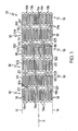
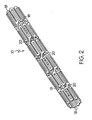
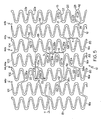
- Figure 1 and Figure 2 show a fragmentary flat view of an unexpanded stent configuration and the actual tubular stent (unexpanded), respectively. That is, the stent is shown for clarity in Figure 1 in the flat and may be made from a flat pattern 10 ( Figure 1 ) which is formed into a tubular shape by rolling the pattern so as to bring edges 12 and 14 together ( Figure 1 ). The edges may then joined as by welding or the like to provide a configuration such as that shown in Figure 2 .
- the configuration can be seen in these Figures to be made up of a plurality of adjacent segments generally indicated at 16, each of which is formed in an undulating flexible pattern of substantially parallel struts 18. Pairs of struts are interconnected at alternating end portions 19a and 19b. As is seen in Figure 1 , the interconnecting end portions 19b of one segment are positioned opposite interconnecting end portions 19a of adjacent segments. The end portions as shown are generally elliptical but may be rounded or square or pointed or the like. Any configuration of end portions is acceptable so long as it provides an undulating pattern, as shown. When the flat form 10 is formed into an unexpanded tube as shown in Figure 2 , the segments are cylindrical but the end portions 19 of adjacent segments remain in an opposed position relative to each other.
- Interconnecting elements 20 extend from one end portion 19 of one segment 16 to another end portion 19 of another adjacent segment 16 but not to an oppositely positioned end portion 19 of an adjacent segment 16. There are at least three struts included between the points on each side of a segment 16 at which an interconnecting element 20 contacts an end portion 19. This results in the interconnecting elements 20 extending in an angular direction between segments around the periphery of the tubular stent. Interconnecting elements 20 are preferably of the same length but may vary from one segment to the other. Also, the diagonal direction may reverse from one segment to another extending upwardly in one case and downwardly in another, although all connecting elements between any pair of segments are substantially parallel. Figure 1 , for example shows them extending downwardly, right to left. Upwardly would extend up left to right in this configuration.
- interconnecting elements 20 may vary depending on circumstances in any particular instance. Three per segment are satisfactory for the configuration shown and at least three will be used typically.
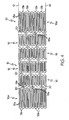
- the alternate design shown in Figure 4 includes longer struts 18a in the two end segments 16a than in the intermediate segments 16. This allows the end segments (16a) to have less compression resistance than the intermediate segments (16), providing a more gradual transition from the native vessel to the support structure of the stent. Otherwise, the configuration is the same as that shown in Figure 1 .
- the segments 16 can also be described as serpentine bands.
- the interconnecting elements 20 can also be described as connector struts.
- the end portions 19 can also be described as turns. End portions 19a can also be described as proximal peaks. End portions 19b can also be described as distal valleys.
- FIG. 5 shows a flat pattern for an embodiment of a stent 10 having a proximal end 13, a distal end 15 and a plurality of serpentine bands 16.
- Each serpentine band 16 comprises a plurality of band struts 22 and a plurality of turns 28.
- the band struts 22 and the turns 28 alternate as the serpentine band 16 is traversed.
- each band strut 22 has a first end 21 connected to one turn 28 and a second end 23 connected to another turn 28.
- Each turn 28 connects between two band struts 22 that are adjacent to one another in a stent circumferential direction.
- a band strut 22 is straight along its length as shown in Figure 5 .
- a band strut 22 can include curvature in one or more directions.
- a serpentine band 16 can further comprise band struts 22 that are shaped differently from one another.
- Other examples of possible configurations of band struts 22 are disclosed in US Patent Application Publication No. 2002/0095208 and US Patent Application No. 1 1/262692 .
- the turns 28 of a serpentine band 16 comprise alternating proximal peaks 24 and distal valleys 26.
- Each proximal peak 24 is generally convex with respect to the proximal end 13 and concave with respect to the distal end 15 of the stent 10.
- Each distal valley 26 is generally convex with respect to the distal end 15 and concave with respect to the proximal end 13 of the stent 10.
- Each turn 28 further comprises an inner side 41 and an outer side 43.
- Proximal peaks 24 are oriented with the outer side 43 closer to the proximal end 13 of the stent 10 than the inner side 41.
- Distal valleys 26 are oriented with the outer side 43 closer to the distal end 15 of the stent 10 than the inner side 41.
- a stent 10 can have any suitable number of serpentine bands 16.
- a serpentine band 16 can have any suitable number of band struts 22 and any suitable number of turns 28.
- a serpentine band 16 can span any suitable distance along the length of the stent 10.
- a stent 10 can comprise serpentine bands 16 that span different distances.
- One method for increasing a lengthwise span of a serpentine band 16 is to increase the length of the band struts 22.
- the proximal peaks 24 of a given serpentine band 16 are aligned around a common circumference of the stent 10, and the distal valleys 26 are similarly aligned around another common circumference of the stent 10.
- Each circumference can be oriented orthogonal to a longitudinal axis 11 of the stent 10.
- an extremity of the outer side 43 of each turn 28 can abut a common reference circumference.
- various peaks 24 can be offset from other peaks 24 within a given serpentine band 16, and various valleys 26 can be offset from other valleys 26 within the band 16.
- Each band strut 22 comprises a width, which may be measured in a direction normal to the length of the strut 22. In some embodiments, all struts 22 within a given serpentine band 16 have the same width. In some embodiments, the width of various struts 22 within a serpentine band 16 can be different from one another. In some embodiments, the width of a strut 22 can change along the length of the strut 22. In some embodiments, the width of struts 22 of one serpentine band 16 can be different from the width of struts 22 of another serpentine band 16.
- Each turn 28 has a width, which may be measured in a direction normal to the side of the turn 28 (e.g. normal to a tangent line). In some embodiments, the width of a turn 28 can be greater than the width of one or more struts 22 of the stent 10. In some embodiments, the width of a turn 28 can be less than the width of one or more struts 22 of the stent 10. In some embodiments, the width of a turn 28 varies from one end of the turn 28 to the other. For example, a turn 28 can connect to a strut 22 at one end having the same width as the strut 22. The width of the turn 28 increases, and in some embodiments reaches a maximum at a midpoint of the turn 28. The width of the turn 28 then decreases to the width of another strut 22, which may be connected to the second end of the turn 28.
- Serpentine bands 16 that are adjacent to one another along the length of the stent 10 are connected by at least one connector strut 20.
- a connector strut 20 spans between turns 28 of adjacent serpentine bands 20.
- a first end 25 of a connector strut 20 can connect to a distal valley 26 of one serpentine band 16, and a second end 27 of the connector strut 20 can connect to a proximal peak 24 of an adjacent serpentine band 16.
- Connector struts 16 can connect to any portion of a serpentine band 16.
- a connector strut 20 connects to a turn 28 as shown in Figure 5 .
- a connector strut 20 can connect to a band strut 22.
- a connector strut 20 is linear or straight along its length.
- a connector strut 20 can include curvature along its length, and can further include multiple portions of curvature, for example a convex portion and a concave portion that may be connected at an inflection point.
- Each connector strut 20 comprises a width, which may be measured in a direction normal to the length of the strut 20. In some embodiments, every connector strut 20 has the same width. In some other embodiments, a connector strut 20 can have a width that is different from another connector strut 20. In some embodiments, the width of a connector strut 20 can change along the length of the strut 20.
- Connector struts 20 comprise a first type of connector strut 36 and a second type of connector strut 38.
- a first connector strut 36 extends in a first direction.
- the first connector strut 36 is oriented at a first angle to a stent lengthwise axis 11.
- a second connector strut 38 extends in a second direction that is different than or non-parallel to the first direction.
- the second connector strut 38 can be oriented at a second angle to a stent lengthwise axis 11.
- the first angle and the second angle can have the same magnitude but different orientations.
- a first connector strut 36 can form a 70° angle with a stent lengthwise axis 11, while a second connector strut 38 can form a negative 70° angle with the stent lengthwise axis 11.
- a first angle may comprise a mirror image of a second angle across a line parallel to the stent lengthwise axis 11.
- first type of connector strut 36 can have a different shape than second type of connector strut 38.
- an area of the stent 10 located between two adjacent serpentine bands 16 can be considered a connector column 44.
- Each connector column 44 comprises a plurality of connector struts 20.
- Each connector strut 20 in a connector column 44 can be similar to one another.
- each connector strut 20 in a first connector column 44a can comprise a first type connector strut 36.
- Each connector strut 20 in a second connector column 44b can comprise a second type of connector strut 38.
- first connector columns 44a and second connector columns 44b can alternate along the length of the stent 10.
- each interior serpentine band 16 can be positioned between a first connector column 44a and a second connector column 44b.
- connector struts 20 that connect to one side of a serpentine band 16 can comprise first connector struts 36
- connector struts 20 that connect to the other side of the serpentine band 16 can comprise second connector struts 38.
- Turns 28 can comprise connected turns 58 or unconnected turns 55 depending upon whether the turn 28 connects to a connector strut 20.
- proximal peaks 26 can comprise connected proximal peaks 64 or unconnected proximal peaks 74
- distal valleys 26 can comprise connected distal valleys 66 or unconnected distal valleys 76.
- a serpentine band 16 can have more unconnected turns 55 than connected turns 58.
- a serpentine band 16 has three unconnected turns 55 for each connected turn 58.
- the 3:1 ratio of unconnected turns 55 to connected turns 58 can also apply to the proximal peaks 24 and to the distal valleys 26.
- a serpentine band 16 there is a repeating pattern ofx number of unconnected turns 55 between one connected turn 58 and the next connected turn 58, and then y number of unconnected turns until the next connected turn 58, wherein y is greater than x.
- a serpentine band 16 can comprise three band struts 22 between the connected turn 58 and the next connected turn 58 in a first direction.
- the serpentine band 16 can further comprise five band struts 22 between the connected turn 58 and the next connected turn 58 in a second direction.
- a serpentine band 16a includes three band struts 22 between a connected turn 58b and the next connected turn 58a in a first circumferential direction 71.
- the serpentine band 16a also includes five band struts 22 between the connected turn 58b and the next connected turn 58c in a second circumferential direction 73.
- a serpentine band 16 there can be a repeating pattern of three band struts 22 between one connected turn 58 and the next connected turn 58, and then five band struts 22 until the next connected turn 58.
- a serpentine band 16a As a serpentine band 16a is traversed from a first connected turn 58a to a second connected turn 58b, there are three band struts 22.
- the serpentine band 16a As the serpentine band 16a is traversed from the second connected turn 58b to a third connected turn 58c, there are five band struts 22.
- the pattern will then repeat, with three band struts 22 between the third connected turn 58c and a fourth connected turn 58d, etc.
- an end serpentine band 16e that is located on the proximal end 13 or the distal end 15 of the stent 10 comprises seven unconnected turns 55 between two connected turns 58.
- the end serpentine band 16e can further comprise eight band struts 22 between two connected turns 58.
- the connector struts 20 of adjacent connector columns 44 are offset from one another in a stent circumferential direction.
- one connector strut 20a is offset in a stent circumferential direction from another connector strut 20b located in an adjacent connector column 44.
- a reference line 8 oriented parallel to the stent longitudinal axis 11 that intersects one connector strut 20a will not intersect the other connector strut 20b.
- the band struts 22 of a serpentine band 16 can comprise alternating first band struts 22a and second band struts 22b.
- each first band strut 22a is parallel to one another as shown in the flat pattern of Figure 5 .
- Each second band strut 22b is parallel to one another and non-parallel to the first band struts 22a.
- Serpentine bands 16 comprises a first type of serpentine band 85 and a second type of serpentine band 89.
- Each first type of serpentine band 85 is aligned with one another such that similar portions of each band 85 align along the length of the stent 10.
- Each second type of serpentine band 89 is aligned with one another such that similar portions of each band 89 align along the length of the stent 10.
- Each first type of serpentine band 85 is offset from each second type of serpentine band 89 such that similar portions of the different types of bands 85, 89 are not aligned along the length of the stent.
- first type of serpentine band 85 and the second type of serpentine band 89 can alternate along the length of the stent 10.
- serpentine bands 16 that are located adjacent to one another along the length of the stent 10 can be offset from one another in a stent circumferential direction. Every other serpentine band 16 can be aligned with one another in a stent circumferential direction.
- a stent 10 can comprise a first serpentine band 16a, a second serpentine band 16b and a third serpentine band 16c along its length.
- the first and third serpentine bands 16a, 16c comprise a first type of serpentine band 85
- the second serpentine band 16b comprises a second type of serpentine band 89.
- the first serpentine band 16a is offset from the second serpentine band 16b in a stent circumferential direction.
- a reference line 8 extending parallel to the stent longitudinal axis 11 will not intersect similar portions of the first serpentine band 16a and the second serpentine band 16b.
- the reference line 8 bisects a proximal peak 24 of the first serpentine band 16a but does not bisect a proximal peak 24 of the second serpentine band 16b.
- the second serpentine band 16b is similarly offset from the third serpentine band 16c.
- the first serpentine band 16a and the third serpentine band 16c are aligned with one another in a stent circumferential direction.
- the reference line 8 bisects a proximal peak 24 of both the first serpentine band 16a and the third serpentine band 16c.
- One serpentine band 16 of a given type 85, 89 can have connected turns 58 that are aligned with unconnected turns 55 of another serpentine band 16 of the same type 85, 89 along the length of the stent 10.
- the first serpentine band 16a of Figure 5 includes a connected turn 58c that is longitudinally aligned with an unconnected turn 55a of the third serpentine band 16c.
- One serpentine band 16 of a given type 85, 89 can have connected turns 58 that are offset from connected turns 58 of the next adjacent serpentine band 16 of the same type 85, 89 by one proximal peak or one distal valley.
- the first serpentine band 16a of Figure 5 includes a connected proximal peak 58c that is offset 6 from a connected proximal peak 58e of the third serpentine band 16c by one proximal peak 24.
- the first serpentine band 16a includes a connected distal valley 58d that is offset from a connected distal valley 58f of the third serpentine band 16c by one distal valley 26.
- the connector struts 20 of adjacent similar types of connector columns 44a, 44b are offset from one another in the stent circumferential direction by an amount equal to the spacing 6, 7 between adjacent proximal peaks 24 or between adjacent distal valleys 26.
- a stent comprises at least a first serpentine band 101, a second serpentine band 102, a third serpentine band 103 and a fourth serpentine band 104.
- Each serpentine band 101-104 comprises connected proximal peaks 64, unconnected proximal peaks 74, connected distal valleys 66 and unconnected distal valleys 76.
- Each serpentine band 101-104 includes at least two unconnected proximal peaks 74 for each connected proximal peak 64, and at least two unconnected distal valleys 76 for each connected distal valley 66.
- a first connector strut 121 connects between a first connected distal valley 130, located on the first serpentine band 101, and a connected proximal peak 64 of the second serpentine band 102.
- a second connector strut 122 connects between the second serpentine band 102 and the third serpentine band 103.
- a third connector strut 123 connects between a second connected distal valley 132, located on the third serpentine band 103, and a connected proximal peak 64 of the fourth serpentine band 104.
- the first connected distal valley 130 is circumferentially aligned with a first unconnected distal valley 116 of the third serpentine band 103.
- the first unconnected distal valley 116 is directly adjacent in a circumferential direction to the second connected distal valley 132.
- Each connected distal valley 66 of the first serpentine band 101 is circumferentially aligned with an unconnected distal valley 76 of the third serpentine band 103. Further, each unconnected distal valley 76 of the third serpentine band 103 that is circumferentially aligned with a connected distal valley 66 of the first, serpentine band 101 is offset from a connected distal valley 66 of the third serpentine band 103 in a circumferential direction by one distal valley (e.g. spacing 7 as shown on Figure 5 ).
- the third connector strut 123 is oriented at a non-zero angle to the stent longitudinal axis 11 and thus comprises a circumferential length component l c oriented in a stent circumferential direction.
- the circumferential length component l c extends from the second connected distal valley 132 in a circumferential direction toward the first unconnected distal valley 116.
- connector struts 20 that connect to connected distal valleys 66 of the third serpentine band 103 extend at an angle to the stent longitudinal axis 11, wherein the angle is oriented in the direction of an adjacent unconnected distal valley 76 (e.g. distal valley 116) that is circumferentially aligned with a connected distal valley 66 (e.g. distal valley 130) of the first serpentine band 101.
- the second serpentine band 102 comprises three band struts 22 between the first connector strut 121 and the second connector strut 122.
- Each connected distal valley 66 of the second serpentine band 102 is circumferentially aligned with an unconnected distal valley 76 of the fourth serpentine band 104. Further, each unconnected distal valley 76 of the fourth serpentine band 104 that is circumferentially aligned with a connected distal valley 66 of the second serpentine band 102 is offset from a connected distal valley 66 of the fourth serpentine band 104 in a circumferential direction by one distal valley (e.g. spacing 7 as shown on Figure 5 ).
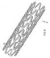
- Figure 6 shows a three-dimensional substantially cylindrical stent 10 according to the flat pattern shown in Figure 5 .
- the stent 10 is shown at a nominal state of expansion and could be further reduced in diameter, for example being crimped onto a delivery catheter, or could be further expanded.
- Figure 7 shows an example of a stent 10 in a state of expansion that is greater than that of Figure 5 .
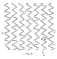
- Figure 8 shows an example of a stent 10 in a state of expansion that is greater than that of Figure 7 .
- Figure 9 shows an example of a stent 10 in a state of expansion that is greater than that of Figure 8 .
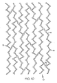
- Figure 10 shows an example of a stent 10 in a state of expansion that is greater than that of Figure 9 .
- the amount of expansion depicted can be described as a state of overexpansion.
- a stent 10 that is actually used in a bodily vessel will be subject to less expansion than the amount shown in Figure 10 .
- the stent 10 pattern shown is capable of providing vessel support even in a substantially overexpanded state.
- the stent as disclosed in the appended claims may be made from any suitable biocompatible materials including one or more polymers, one or more metals or combinations of polymer(s) and metal(s).
- suitable materials include biodegradable materials that are also biocompatible.
- biodegradable is meant that a material will undergo breakdown or decomposition into harmless compounds as part of a normal biological process.
- Suitable biodegradable materials include polylactic acid, polyglycolic acid (PGA), collagen or other connective proteins or natural materials, polycaprolactone, hylauric acid, adhesive proteins, co-polymers of these materials as well as composites and combinations thereof and combinations of other biodegradable polymers.
- Other polymers that may be used include polyester and polycarbonate copolymers.
- suitable metals include, but are not limited to, stainless steel, titanium, tantalum, platinum, tungsten, gold and alloys of any of the above-mentioned metals.
- suitable alloys include platinum-iridium alloys, cobalt-chromium alloys including Elgiloy and Phynox, MP35N alloy and nickel-titanium alloys, for example, Nitinol.
- the stent as disclosed in the appended claims may be made of shape memory materials such as superelastic Nitinol or spring steel, or may be made of materials which are plastically deformable.
- shape memory materials such as superelastic Nitinol or spring steel, or may be made of materials which are plastically deformable.
- the stent may be provided with a memorized shape and then deformed to a reduced diameter shape. The stent may restore itself to its memorized shape upon being heated to a transition temperature and having any restraints removed therefrom.
- the stents as disclosed in the appended claims may be created by methods including cutting or etching a design from a tubular stock, from a flat sheet which is cut or etched and which is subsequently rolled or from one or more interwoven wires or braids. Any other suitable technique which is known in the art or which is subsequently developed may also be used to manufacture the inventive stents disclosed herein.
- the stent, the delivery system or other portion of the assembly may include one or more areas, bands, coatings, members, etc. that is (are) detectable by imaging modalities such as X-Ray, MRI, ultrasound, etc.
- imaging modalities such as X-Ray, MRI, ultrasound, etc.
- at least a portion of the stent and/or adjacent assembly is at least partially radiopaque.
- the at least a portion of the stent is configured to include one or more mechanisms for the delivery of a therapeutic agent.
- the agent will be in the form of a coating or other layer (or layers) of material placed on a surface region of the stent, which is adapted to be released at the site of the stent's implantation or areas adjacent thereto.
- a therapeutic agent may be a drug or other pharmaceutical product such as non-genetic agents, genetic agents, cellular material, etc.
- suitable non-genetic therapeutic agents include but are not limited to: anti-thrombogenic agents such as heparin, heparin derivatives, vascular cell growth promoters, growth factor inhibitors, Paclitaxel, etc.
- therapeutic agents include everolimus and sirolimus, their analogs and conjugates.
- an agent includes a genetic therapeutic agent, such a genetic agent may include but is not limited to: DNA, RNA and their respective derivatives and/or components; hedgehog proteins, etc.
- the cellular material may include but is not limited to: cells of human origin and/or non-human origin as well as their respective components and/or derivatives thereof.
- the therapeutic agent includes a polymer agent
- the polymer agent may be a polystyrene-polyisobutylene-polystyrene triblock copolymer (SIBS), polyethylene oxide, silicone rubber and/or any other suitable substrate.
Landscapes
- Health & Medical Sciences (AREA)
- Engineering & Computer Science (AREA)
- Biomedical Technology (AREA)
- Heart & Thoracic Surgery (AREA)
- Life Sciences & Earth Sciences (AREA)
- Cardiology (AREA)
- Oral & Maxillofacial Surgery (AREA)
- Transplantation (AREA)
- Physics & Mathematics (AREA)
- Vascular Medicine (AREA)
- Optics & Photonics (AREA)
- Animal Behavior & Ethology (AREA)
- General Health & Medical Sciences (AREA)
- Public Health (AREA)
- Veterinary Medicine (AREA)
- Prostheses (AREA)
- Media Introduction/Drainage Providing Device (AREA)
Claims (13)
- Stent (10) umfassend• eine Vielzahl von serpentinenförmigen Bändern (16) und eine Vielzahl von Verbindersäulen (44), wobei jedes serpentinenförmige Band eine Vielzahl von geraden Bandstreben (22) und Kehren umfasst, die sich abwechseln,• aneinander angrenzende serpentinenförmige Bänder (16), die quer über eine Verbindersäule (44) hinweg durch eine Vielzahl von Verbinderstreben (20) verbunden sind,• wobei jede Verbinderstrebe (20) an einem Ende mit einer Kehre eines serpentinenförmigen Bandes (16) verbunden ist und an dem anderen Ende mit einer Kehre eines anderen serpentinenförmigen Bandes (16) verbunden ist,• wobei die Kehren eines serpentinenförmigen Bandes verbundene Kehren (58) umfassen, welche zu einer Verbinderstrebe verbinden, sowie unverbundene Kehren (55), die nicht zu einer Verbinderstrebe (20) verbinden,• wobei mindestes eines der serpentinenförmigen Bänder (16) ein sich wiederholendes Muster aus drei Bandstreben (22) und dann fünf sich zwischen verbundenen Kehren (58) erstreckenden Bandstreben (22) umfasst, wenn das serpentinenförmige Band (16) durchquert wird,• wobei die Verbindersäulen (44) erste Verbindersäulen (44a) und zweite Verbindersäulen (44b) umfassen, Verbinderstreben (20a) der ersten Verbindersäulen (44a) parallel zueinander sind und Verbinderstreben (20b) der zweiten Verbindersäulen (44b) nicht parallel zu den Verbinderstreben (20) der ersten Verbindersäulen (44a) sind,
dadurch gekennzeichnet dass• die serpentinenförmigen Bänder (16) erste serpentinenförmige Bänder (85) und zweite serpentinenförmige Bänder (89) umfassen, Kehren der ersten serpentinenförmigen Bänder (85) in der Längsrichtung des Stents zueinander ausgerichtet sind und Kehren der ersten serpentinenförmigen Bänder (85) in der Längsrichtung des Stents gegenüber Kehren der zweiten serpentinenförmigen Bänder (89) versetzt sind. - Stent gemäß Anspruch 1, wobei eine Vielzahl der serpentinenförmigen Bänder (16) ein sich wiederholendes Muster aus drei Bandstreben (22) und dann fünf sich zwischen verbundenen Kehren erstreckenden Bandstreben umfassen.
- Stent gemäß Anspruch 2, umfassend mindestens ein serpentinenförmiges Band (16) mit acht sich zwischen verbundenen Kehren (58) erstreckenden Bandstreben.
- Stent gemäß Anspruch 3, wobei erste serpentinenförmige Bänder (16) und zweite serpentinenförmige Bänder (16) sich entlang der Länge des Stents (10) abwechseln.
- Stent gemäß Anspruch 4, wobei eine verbundene Kehre (58) eines ersten serpentinenförmigen Bandes mit einer unverbundenen Kehre (55) eines angrenzenden ersten serpentinenförmigen Bandes (16) in der Längsrichtung des Stents fluchtet.
- Stent gemäß Anspruch 5, wobei erste Verbindersäulen (44) und zweite Verbindersäulen (44) sich entlang der Länge des Stents abwechseln.
- Stent gemäß Anspruch 1, wobei die maximale Breite einer Bandstrebe (22) geringer ist als die maximale Breite einer Kehre.
- Stent gemäß Anspruch 1, wobei die Kehren eines serpentinenförmigen Bandes sich abwechselnde proximale Gipfel und distale Täler umfassen, wobei die proximalen Gipfel eines serpentinenförmigen Bandes (16) über einem gemeinsamen Umfang des Stents (10) ausgerichtet sind.
- Stent gemäß Anspruch 8, wobei ein gegebenes serpentinenförmiges Band drei Bandstreben (22) umfasst, die sich zwischen einem ersten verbundenen proximalen Gipfel (64), welcher zu einer Verbinderstrebe (20) verbindet, und einem ersten verbundenen distalen Tal (130) erstrecken, welches zu einer Verbinderstrebe (20) verbindet, und es ferner fünf sich zwischen dem ersten verbundenen distalen Tal (130) und einem zweiten verbundenen proximalen Gipfel (64) erstreckende Bandstreben (22) umfasst.
- Stent gemäß Anspruch 9, wobei das gegebene serpentinenförmige Band (16) ferner drei Bandstreben (22) umfasst, die sich zwischen dem zweiten verbundenen proximalen Gipfel (64) und einem zweiten verbundenen distalen Tal (132) erstrecken, sowie fünf Bandstreben (22), die sich zwischen dem zweiten verbundenen distalen Tal (132) und dem ersten verbundenen proximalen Gipfel (64) erstrecken.
- Stent gemäß Anspruch 1, wobei ein gegebenes serpentinenförmiges Band zwei unverbundene Kehren (55) zwischen einer ersten verbundenen Kehre (58) und einer zweiten verbundenen Kehre (58) sowie vier unverbundene Kehren (55) zwischen der zweiten verbundenen Kehre (58) und einer dritten verbundenen Kehre (58) umfasst, wenn das serpentinenförmige Band (16) durchquert wird.
- Stent gemäß Anspruch 11, wobei das gegebene serpentinenförmige Band (16) ferner zwei unverbundene Kehren (55) zwischen der dritten verbundenen Kehre (58) und einer vierten verbundenen Kehre (58) umfasst, sowie vier unverbundene Kehren (55) zwischen der vierten verbundenen Kehre (58) und der ersten verbundenen Kehre (58), wenn das serpentinenförmige Band (16) durchquert wird.
- Stent gemäß Anspruch 12, wobei Verbinderstreben (20), welche zu der ersten verbundenen Kehre (58) und der dritten verbundenen Kehre (58) verbinden, parallel zueinander und nicht-parallel zu Verbinderstreben (20) sind, welche zu der zweiten verbundenen Kehre (58) und der vierten verbundenen Kehre (58) verbinden.
Applications Claiming Priority (2)
| Application Number | Priority Date | Filing Date | Title |
|---|---|---|---|
| US11/519,552 US20070073384A1 (en) | 1995-03-01 | 2006-09-12 | Longitudinally flexible expandable stent |
| PCT/US2007/013714 WO2008033174A2 (en) | 2006-09-12 | 2007-06-12 | Longitudinally flexible expandable stent |
Publications (2)
| Publication Number | Publication Date |
|---|---|
| EP2059199A2 EP2059199A2 (de) | 2009-05-20 |
| EP2059199B1 true EP2059199B1 (de) | 2012-08-01 |
Family
ID=39032125
Family Applications (1)
| Application Number | Title | Priority Date | Filing Date |
|---|---|---|---|
| EP07809466A Active EP2059199B1 (de) | 2006-09-12 | 2007-06-12 | In längsrichtung flexibler expandierbarer stent |
Country Status (6)
| Country | Link |
|---|---|
| US (1) | US20070073384A1 (de) |
| EP (1) | EP2059199B1 (de) |
| JP (1) | JP5140675B2 (de) |
| CA (1) | CA2661339A1 (de) |
| ES (1) | ES2390982T3 (de) |
| WO (1) | WO2008033174A2 (de) |
Families Citing this family (26)
| Publication number | Priority date | Publication date | Assignee | Title |
|---|---|---|---|---|
| US7204848B1 (en) | 1995-03-01 | 2007-04-17 | Boston Scientific Scimed, Inc. | Longitudinally flexible expandable stent |
| US7341598B2 (en) | 1999-01-13 | 2008-03-11 | Boston Scientific Scimed, Inc. | Stent with protruding branch portion for bifurcated vessels |
| EP0884029B1 (de) | 1997-06-13 | 2004-12-22 | Gary J. Becker | Expandierbare intraluminale Endoprothese |
| US7578841B2 (en) | 2001-09-24 | 2009-08-25 | Boston Scientific Scimed, Inc. | Stent with protruding branch portion for bifurcated vessels |
| US9427340B2 (en) * | 2004-12-14 | 2016-08-30 | Boston Scientific Scimed, Inc. | Stent with protruding branch portion for bifurcated vessels |
| US7540881B2 (en) | 2005-12-22 | 2009-06-02 | Boston Scientific Scimed, Inc. | Bifurcation stent pattern |
| US9393135B2 (en) * | 2006-05-12 | 2016-07-19 | CARDINAL HEALTH SWITZERLAND 515 GmbH | Balloon expandable bioabsorbable drug eluting stent |
| US20080065197A1 (en) * | 2006-09-12 | 2008-03-13 | Boston Scientific Scimed, Inc. | Bifurcated Stent |
| US7951191B2 (en) | 2006-10-10 | 2011-05-31 | Boston Scientific Scimed, Inc. | Bifurcated stent with entire circumferential petal |
| US7842082B2 (en) * | 2006-11-16 | 2010-11-30 | Boston Scientific Scimed, Inc. | Bifurcated stent |
| US8211162B2 (en) * | 2007-05-25 | 2012-07-03 | Boston Scientific Scimed, Inc. | Connector node for durable stent |
| US7959669B2 (en) | 2007-09-12 | 2011-06-14 | Boston Scientific Scimed, Inc. | Bifurcated stent with open ended side branch support |
| US7833266B2 (en) | 2007-11-28 | 2010-11-16 | Boston Scientific Scimed, Inc. | Bifurcated stent with drug wells for specific ostial, carina, and side branch treatment |
| US8277501B2 (en) | 2007-12-21 | 2012-10-02 | Boston Scientific Scimed, Inc. | Bi-stable bifurcated stent petal geometry |
| US8932340B2 (en) | 2008-05-29 | 2015-01-13 | Boston Scientific Scimed, Inc. | Bifurcated stent and delivery system |
| WO2010118432A1 (en) * | 2009-04-10 | 2010-10-14 | Ev3 Inc. | Implants having high fatigue resistance, implant delivery systems, and methods of use |
| US8114149B2 (en) * | 2009-10-20 | 2012-02-14 | Svelte Medical Systems, Inc. | Hybrid stent with helical connectors |
| US9211123B2 (en) * | 2009-12-31 | 2015-12-15 | Cook Medical Technologies Llc | Intraluminal occlusion devices and methods of blocking the entry of fluid into bodily passages |
| US8348993B2 (en) * | 2010-03-29 | 2013-01-08 | Boston Scientific Scimed, Inc. | Flexible stent design |
| CN106667630B (zh) | 2012-05-14 | 2019-03-29 | C·R·巴德公司 | 可均匀膨胀的支架 |
| US9498359B2 (en) * | 2012-07-13 | 2016-11-22 | Abbott Cardiovascular Systems Inc. | Polymer scaffolds for peripheral vessels |
| USD723165S1 (en) | 2013-03-12 | 2015-02-24 | C. R. Bard, Inc. | Stent |
| US9662231B2 (en) | 2013-03-15 | 2017-05-30 | Abbott Cardiovascular Systems Inc. | Polymer scaffolds having enhanced axial fatigue properties |
| EP3089769A1 (de) | 2014-01-02 | 2016-11-09 | Boston Scientific Scimed, Inc. | Wirkstofffreisetzender ballon mit bevorzugter arzneimittelausrichtung zur verbesserung der arzneimittelübertragungsleistung |
| US20160067070A1 (en) * | 2014-09-04 | 2016-03-10 | Boston Scientific Scimed, Inc. | Bioerodible polymeric stent scaffolding pattern |
| WO2016044788A2 (en) | 2014-09-18 | 2016-03-24 | Abbott Cardiovascular Systems Inc. | Thermal processing of polymer scaffolds |
Family Cites Families (103)
| Publication number | Priority date | Publication date | Assignee | Title |
|---|---|---|---|---|
| GB1104680A (en) * | 1965-10-18 | 1968-02-28 | Univ Birmingham | Artificial artery |
| AT261800B (de) * | 1966-08-22 | 1968-05-10 | Braun Internat Gmbh B | Verfahren zur Herstellung von röhrenförmigen, glatten bzw. mit einem Gewinde versehenen Gewebe-Blutgefäß-Prothesen |
| US3635215A (en) * | 1969-08-14 | 1972-01-18 | Gam Rad | Medical removal hook |
| US3657744A (en) * | 1970-05-08 | 1972-04-25 | Univ Minnesota | Method for fixing prosthetic implants in a living body |
| US3868956A (en) * | 1972-06-05 | 1975-03-04 | Ralph J Alfidi | Vessel implantable appliance and method of implanting it |
| US4078167A (en) * | 1977-02-09 | 1978-03-07 | United Technologies Corporation | Welding shield and plasma suppressor apparatus |
| US4140126A (en) * | 1977-02-18 | 1979-02-20 | Choudhury M Hasan | Method for performing aneurysm repair |
| US4141364A (en) * | 1977-03-18 | 1979-02-27 | Jorge Schultze | Expandable endotracheal or urethral tube |
| AU516741B2 (en) * | 1978-05-23 | 1981-06-18 | Bio Nova Neo Technics Pty. Ltd. | Vascular prostheses |
| WO1980000007A1 (en) * | 1978-06-02 | 1980-01-10 | A Rockey | Medical sleeve |
| JPS6028434Y2 (ja) * | 1980-06-16 | 1985-08-28 | 建部 容保 | 人工血管 |
| US4441215A (en) * | 1980-11-17 | 1984-04-10 | Kaster Robert L | Vascular graft |
| US4425908A (en) * | 1981-10-22 | 1984-01-17 | Beth Israel Hospital | Blood clot filter |
| SE445884B (sv) * | 1982-04-30 | 1986-07-28 | Medinvent Sa | Anordning for implantation av en rorformig protes |
| US4512338A (en) * | 1983-01-25 | 1985-04-23 | Balko Alexander B | Process for restoring patency to body vessels |
| US4503569A (en) * | 1983-03-03 | 1985-03-12 | Dotter Charles T | Transluminally placed expandable graft prosthesis |
| US4647416A (en) * | 1983-08-03 | 1987-03-03 | Shiley Incorporated | Method of preparing a vascular graft prosthesis |
| US5104399A (en) * | 1986-12-10 | 1992-04-14 | Endovascular Technologies, Inc. | Artificial graft and implantation method |
| US4655776A (en) * | 1984-01-12 | 1987-04-07 | Oto Enterprises, Inc. | Prostheses for ossicular reconstruction |
| US4580568A (en) * | 1984-10-01 | 1986-04-08 | Cook, Incorporated | Percutaneous endovascular stent and method for insertion thereof |
| JPH0760544B2 (ja) * | 1985-07-17 | 1995-06-28 | ソニー株式会社 | 記録再生装置のテ−プガイド機構 |
| US4733665C2 (en) * | 1985-11-07 | 2002-01-29 | Expandable Grafts Partnership | Expandable intraluminal graft and method and apparatus for implanting an expandable intraluminal graft |
| US5102417A (en) * | 1985-11-07 | 1992-04-07 | Expandable Grafts Partnership | Expandable intraluminal graft, and method and apparatus for implanting an expandable intraluminal graft |
| US4649922A (en) * | 1986-01-23 | 1987-03-17 | Wiktor Donimik M | Catheter arrangement having a variable diameter tip and spring prosthesis |
| US4740207A (en) * | 1986-09-10 | 1988-04-26 | Kreamer Jeffry W | Intralumenal graft |
| US4800882A (en) * | 1987-03-13 | 1989-01-31 | Cook Incorporated | Endovascular stent and delivery system |
| US4795465A (en) * | 1987-05-14 | 1989-01-03 | Hood Laboratories | Tracheobronchial stent |
| US4795458A (en) * | 1987-07-02 | 1989-01-03 | Regan Barrie F | Stent for use following balloon angioplasty |
| JPS6446477A (en) * | 1987-08-13 | 1989-02-20 | Terumo Corp | Catheter |
| US4820298A (en) * | 1987-11-20 | 1989-04-11 | Leveen Eric G | Internal vascular prosthesis |
| US5092877A (en) * | 1988-09-01 | 1992-03-03 | Corvita Corporation | Radially expandable endoprosthesis |
| US5108415A (en) * | 1988-10-04 | 1992-04-28 | Cordis Corporation | Balloons for medical devices and fabrication thereof |
| CA1322628C (en) * | 1988-10-04 | 1993-10-05 | Richard A. Schatz | Expandable intraluminal graft |
| US4913141A (en) * | 1988-10-25 | 1990-04-03 | Cordis Corporation | Apparatus and method for placement of a stent within a subject vessel |
| US5091205A (en) * | 1989-01-17 | 1992-02-25 | Union Carbide Chemicals & Plastics Technology Corporation | Hydrophilic lubricious coatings |
| DE8903978U1 (de) * | 1989-04-01 | 1989-06-08 | Wampfler Gmbh, 7858 Weil | Stoßverbindungsvorrichtung |
| US4994071A (en) * | 1989-05-22 | 1991-02-19 | Cordis Corporation | Bifurcating stent apparatus and method |
| US5292331A (en) * | 1989-08-24 | 1994-03-08 | Applied Vascular Engineering, Inc. | Endovascular support device |
| US5304121A (en) * | 1990-12-28 | 1994-04-19 | Boston Scientific Corporation | Drug delivery system making use of a hydrogel polymer coating |
| US5108417A (en) * | 1990-09-14 | 1992-04-28 | Interface Biomedical Laboratories Corp. | Anti-turbulent, anti-thrombogenic intravascular stent |
| DE69118083T2 (de) * | 1990-10-09 | 1996-08-22 | Cook Inc | Perkutane Stentanordnung |
| US5197978B1 (en) * | 1991-04-26 | 1996-05-28 | Advanced Coronary Tech | Removable heat-recoverable tissue supporting device |
| US5304200A (en) * | 1991-05-29 | 1994-04-19 | Cordis Corporation | Welded radially expandable endoprosthesis and the like |
| CA2079417C (en) * | 1991-10-28 | 2003-01-07 | Lilip Lau | Expandable stents and method of making same |
| FR2683449A1 (fr) * | 1991-11-08 | 1993-05-14 | Cardon Alain | Endoprothese pour implantation transluminale. |
| US5507767A (en) * | 1992-01-15 | 1996-04-16 | Cook Incorporated | Spiral stent |
| US5405377A (en) * | 1992-02-21 | 1995-04-11 | Endotech Ltd. | Intraluminal stent |
| US5282823A (en) * | 1992-03-19 | 1994-02-01 | Medtronic, Inc. | Intravascular radially expandable stent |
| US5599352A (en) * | 1992-03-19 | 1997-02-04 | Medtronic, Inc. | Method of making a drug eluting stent |
| DE4303181A1 (de) * | 1993-02-04 | 1994-08-11 | Angiomed Ag | Implantierbarer Katheter |
| US5389106A (en) * | 1993-10-29 | 1995-02-14 | Numed, Inc. | Impermeable expandable intravascular stent |
| US5609627A (en) * | 1994-02-09 | 1997-03-11 | Boston Scientific Technology, Inc. | Method for delivering a bifurcated endoluminal prosthesis |
| US5733303A (en) * | 1994-03-17 | 1998-03-31 | Medinol Ltd. | Flexible expandable stent |
| US6165210A (en) * | 1994-04-01 | 2000-12-26 | Gore Enterprise Holdings, Inc. | Self-expandable helical intravascular stent and stent-graft |
| JP2825452B2 (ja) * | 1994-04-25 | 1998-11-18 | アドヴァンスド カーディオヴァスキュラー システムズ インコーポレーテッド | ラジオパク・ステント・マーカ |
| DE4418336A1 (de) * | 1994-05-26 | 1995-11-30 | Angiomed Ag | Stent |
| EP1051953A3 (de) * | 1994-06-17 | 2001-02-28 | Terumo Kabushiki Kaisha | Dauerstent und Verfahren zu seiner Herstellung |
| US5591230A (en) * | 1994-09-07 | 1997-01-07 | Global Therapeutics, Inc. | Radially expandable stent |
| US7204848B1 (en) * | 1995-03-01 | 2007-04-17 | Boston Scientific Scimed, Inc. | Longitudinally flexible expandable stent |
| ATE395014T1 (de) * | 1995-03-01 | 2008-05-15 | Boston Scient Scimed Inc | Längsflexibler und expandierbarer stent |
| US6981986B1 (en) * | 1995-03-01 | 2006-01-03 | Boston Scientific Scimed, Inc. | Longitudinally flexible expandable stent |
| US5591197A (en) * | 1995-03-14 | 1997-01-07 | Advanced Cardiovascular Systems, Inc. | Expandable stent forming projecting barbs and method for deploying |
| DK0734698T4 (da) * | 1995-04-01 | 2006-07-03 | Variomed Ag | Stent til transluminal implantation i hule organer |
| US5613981A (en) * | 1995-04-21 | 1997-03-25 | Medtronic, Inc. | Bidirectional dual sinusoidal helix stent |
| US5593442A (en) * | 1995-06-05 | 1997-01-14 | Localmed, Inc. | Radially expansible and articulated vessel scaffold |
| US6017363A (en) * | 1997-09-22 | 2000-01-25 | Cordis Corporation | Bifurcated axially flexible stent |
| NZ331269A (en) * | 1996-04-10 | 2000-01-28 | Advanced Cardiovascular System | Expandable stent, its structural strength varying along its length |
| US6039756A (en) * | 1996-04-26 | 2000-03-21 | Jang; G. David | Intravascular stent |
| US6123712A (en) * | 1996-08-23 | 2000-09-26 | Scimed Life Systems, Inc. | Balloon catheter with stent securement means |
| US6206911B1 (en) * | 1996-12-19 | 2001-03-27 | Simcha Milo | Stent combination |
| US5868782A (en) * | 1996-12-24 | 1999-02-09 | Global Therapeutics, Inc. | Radially expandable axially non-contracting surgical stent |
| DE29702671U1 (de) * | 1997-02-17 | 1997-04-10 | Jomed Implantate GmbH, 72414 Rangendingen | Stent |
| US6033433A (en) * | 1997-04-25 | 2000-03-07 | Scimed Life Systems, Inc. | Stent configurations including spirals |
| DE29708879U1 (de) * | 1997-05-20 | 1997-07-31 | Jomed Implantate GmbH, 72414 Rangendingen | Koronarer Stent |
| US5855600A (en) * | 1997-08-01 | 1999-01-05 | Inflow Dynamics Inc. | Flexible implantable stent with composite design |
| US6190406B1 (en) * | 1998-01-09 | 2001-02-20 | Nitinal Development Corporation | Intravascular stent having tapered struts |
| US6342067B1 (en) * | 1998-01-09 | 2002-01-29 | Nitinol Development Corporation | Intravascular stent having curved bridges for connecting adjacent hoops |
| US6179867B1 (en) * | 1998-01-16 | 2001-01-30 | Advanced Cardiovascular Systems, Inc. | Flexible stent and method of use |
| US6200334B1 (en) * | 1998-02-03 | 2001-03-13 | G. David Jang | Tubular stent consists of non-parallel expansion struts and contralaterally attached diagonal connectors |
| US6132460A (en) * | 1998-03-27 | 2000-10-17 | Intratherapeutics, Inc. | Stent |
| US6361759B1 (en) * | 1998-05-26 | 2002-03-26 | Wisconsin Alumni Research Foundation | MR signal-emitting coatings |
| US6261319B1 (en) | 1998-07-08 | 2001-07-17 | Scimed Life Systems, Inc. | Stent |
| US6193744B1 (en) * | 1998-09-10 | 2001-02-27 | Scimed Life Systems, Inc. | Stent configurations |
| US6042597A (en) * | 1998-10-23 | 2000-03-28 | Scimed Life Systems, Inc. | Helical stent design |
| US6190403B1 (en) * | 1998-11-13 | 2001-02-20 | Cordis Corporation | Low profile radiopaque stent with increased longitudinal flexibility and radial rigidity |
| US6503270B1 (en) * | 1998-12-03 | 2003-01-07 | Medinol Ltd. | Serpentine coiled ladder stent |
| US6355059B1 (en) * | 1998-12-03 | 2002-03-12 | Medinol, Ltd. | Serpentine coiled ladder stent |
| US6187034B1 (en) * | 1999-01-13 | 2001-02-13 | John J. Frantzen | Segmented stent for flexible stent delivery system |
| US6312457B1 (en) * | 1999-04-01 | 2001-11-06 | Boston Scientific Corporation | Intraluminal lining |
| US6273911B1 (en) * | 1999-04-22 | 2001-08-14 | Advanced Cardiovascular Systems, Inc. | Variable strength stent |
| US6551351B2 (en) * | 1999-07-02 | 2003-04-22 | Scimed Life Systems | Spiral wound stent |
| US6355063B1 (en) * | 2000-01-20 | 2002-03-12 | Impra, Inc. | Expanded PTFE drug delivery graft |
| US6520984B1 (en) * | 2000-04-28 | 2003-02-18 | Cardiovasc, Inc. | Stent graft assembly and method |
| US8070792B2 (en) | 2000-09-22 | 2011-12-06 | Boston Scientific Scimed, Inc. | Stent |
| US6506211B1 (en) * | 2000-11-13 | 2003-01-14 | Scimed Life Systems, Inc. | Stent designs |
| US20030033007A1 (en) * | 2000-12-22 | 2003-02-13 | Avantec Vascular Corporation | Methods and devices for delivery of therapeutic capable agents with variable release profile |
| US6605110B2 (en) * | 2001-06-29 | 2003-08-12 | Advanced Cardiovascular Systems, Inc. | Stent with enhanced bendability and flexibility |
| JP3605388B2 (ja) * | 2001-10-16 | 2004-12-22 | 川澄化学工業株式会社 | ステント |
| JP3663192B2 (ja) * | 2001-10-16 | 2005-06-22 | 川澄化学工業株式会社 | ステント |
| US20030225448A1 (en) * | 2002-05-28 | 2003-12-04 | Scimed Life Systems, Inc. | Polar radiopaque marker for stent |
| US7025777B2 (en) * | 2002-07-31 | 2006-04-11 | Unison Therapeutics, Inc. | Flexible and conformable stent and method of forming same |
| US7112216B2 (en) | 2003-05-28 | 2006-09-26 | Boston Scientific Scimed, Inc. | Stent with tapered flexibility |
| US7404823B2 (en) * | 2005-10-31 | 2008-07-29 | Boston Scientific Scimed, Inc. | Stent configurations |
-
2006
- 2006-09-12 US US11/519,552 patent/US20070073384A1/en not_active Abandoned
-
2007
- 2007-06-12 ES ES07809466T patent/ES2390982T3/es active Active
- 2007-06-12 JP JP2009527341A patent/JP5140675B2/ja not_active Expired - Fee Related
- 2007-06-12 EP EP07809466A patent/EP2059199B1/de active Active
- 2007-06-12 CA CA002661339A patent/CA2661339A1/en not_active Abandoned
- 2007-06-12 WO PCT/US2007/013714 patent/WO2008033174A2/en active Application Filing
Also Published As
| Publication number | Publication date |
|---|---|
| US20070073384A1 (en) | 2007-03-29 |
| CA2661339A1 (en) | 2008-03-20 |
| WO2008033174A2 (en) | 2008-03-20 |
| JP2010503425A (ja) | 2010-02-04 |
| WO2008033174A3 (en) | 2008-05-08 |
| ES2390982T3 (es) | 2012-11-20 |
| EP2059199A2 (de) | 2009-05-20 |
| JP5140675B2 (ja) | 2013-02-06 |
Similar Documents
| Publication | Publication Date | Title |
|---|---|---|
| EP2059199B1 (de) | In längsrichtung flexibler expandierbarer stent | |
| EP1954223B1 (de) | Stentkonfigurationen | |
| EP3119354B1 (de) | Stententwurf für reduzierte granulierung und entzündung | |
| US7988720B2 (en) | Longitudinally flexible expandable stent | |
| EP1903998B1 (de) | Hybridstent | |
| US7540881B2 (en) | Bifurcation stent pattern | |
| US8211163B2 (en) | Hybrid symmetrical stent designs | |
| US8414637B2 (en) | Stent | |
| EP2529707A1 (de) | Endoprothese mit Fussverlängerungen | |
| EP2086475B1 (de) | Gegabelter stent | |
| WO2007102961A1 (en) | Bifurcated stent with surface area gradient | |
| EP2073766B1 (de) | Verzweigter stent mit einem vollständig umlaufenden ring |
Legal Events
| Date | Code | Title | Description |
|---|---|---|---|
| PUAI | Public reference made under article 153(3) epc to a published international application that has entered the european phase |
Free format text: ORIGINAL CODE: 0009012 |
|
| 17P | Request for examination filed |
Effective date: 20090319 |
|
| AK | Designated contracting states |
Kind code of ref document: A2 Designated state(s): AT BE BG CH CY CZ DE DK EE ES FI FR GB GR HU IE IS IT LI LT LU LV MC MT NL PL PT RO SE SI SK TR |
|
| AX | Request for extension of the european patent |
Extension state: AL BA HR MK RS |
|
| RIN1 | Information on inventor provided before grant (corrected) |
Inventor name: CHOUINARD, PAUL F. Inventor name: GREGORICH, DANIEL Inventor name: MEYER, MICHAEL P. Inventor name: DAVIS, MICHAEL L. Inventor name: BROWN, BRIAN J. |
|
| DAX | Request for extension of the european patent (deleted) | ||
| 17Q | First examination report despatched |
Effective date: 20110519 |
|
| GRAP | Despatch of communication of intention to grant a patent |
Free format text: ORIGINAL CODE: EPIDOSNIGR1 |
|
| GRAS | Grant fee paid |
Free format text: ORIGINAL CODE: EPIDOSNIGR3 |
|
| GRAA | (expected) grant |
Free format text: ORIGINAL CODE: 0009210 |
|
| AK | Designated contracting states |
Kind code of ref document: B1 Designated state(s): AT BE BG CH CY CZ DE DK EE ES FI FR GB GR HU IE IS IT LI LT LU LV MC MT NL PL PT RO SE SI SK TR |
|
| REG | Reference to a national code |
Ref country code: GB Ref legal event code: FG4D |
|
| REG | Reference to a national code |
Ref country code: CH Ref legal event code: EP Ref country code: AT Ref legal event code: REF Ref document number: 568232 Country of ref document: AT Kind code of ref document: T Effective date: 20120815 |
|
| REG | Reference to a national code |
Ref country code: NL Ref legal event code: T3 Ref country code: IE Ref legal event code: FG4D |
|
| REG | Reference to a national code |
Ref country code: DE Ref legal event code: R096 Ref document number: 602007024395 Country of ref document: DE Effective date: 20120927 |
|
| REG | Reference to a national code |
Ref country code: ES Ref legal event code: FG2A Ref document number: 2390982 Country of ref document: ES Kind code of ref document: T3 Effective date: 20121120 |
|
| REG | Reference to a national code |
Ref country code: AT Ref legal event code: MK05 Ref document number: 568232 Country of ref document: AT Kind code of ref document: T Effective date: 20120801 |
|
| REG | Reference to a national code |
Ref country code: LT Ref legal event code: MG4D Effective date: 20120801 |
|
| PG25 | Lapsed in a contracting state [announced via postgrant information from national office to epo] |
Ref country code: FI Free format text: LAPSE BECAUSE OF FAILURE TO SUBMIT A TRANSLATION OF THE DESCRIPTION OR TO PAY THE FEE WITHIN THE PRESCRIBED TIME-LIMIT Effective date: 20120801 Ref country code: IS Free format text: LAPSE BECAUSE OF FAILURE TO SUBMIT A TRANSLATION OF THE DESCRIPTION OR TO PAY THE FEE WITHIN THE PRESCRIBED TIME-LIMIT Effective date: 20121201 Ref country code: CY Free format text: LAPSE BECAUSE OF FAILURE TO SUBMIT A TRANSLATION OF THE DESCRIPTION OR TO PAY THE FEE WITHIN THE PRESCRIBED TIME-LIMIT Effective date: 20120801 Ref country code: AT Free format text: LAPSE BECAUSE OF FAILURE TO SUBMIT A TRANSLATION OF THE DESCRIPTION OR TO PAY THE FEE WITHIN THE PRESCRIBED TIME-LIMIT Effective date: 20120801 Ref country code: LT Free format text: LAPSE BECAUSE OF FAILURE TO SUBMIT A TRANSLATION OF THE DESCRIPTION OR TO PAY THE FEE WITHIN THE PRESCRIBED TIME-LIMIT Effective date: 20120801 |
|
| PG25 | Lapsed in a contracting state [announced via postgrant information from national office to epo] |
Ref country code: PT Free format text: LAPSE BECAUSE OF FAILURE TO SUBMIT A TRANSLATION OF THE DESCRIPTION OR TO PAY THE FEE WITHIN THE PRESCRIBED TIME-LIMIT Effective date: 20121203 Ref country code: BE Free format text: LAPSE BECAUSE OF FAILURE TO SUBMIT A TRANSLATION OF THE DESCRIPTION OR TO PAY THE FEE WITHIN THE PRESCRIBED TIME-LIMIT Effective date: 20120801 Ref country code: GR Free format text: LAPSE BECAUSE OF FAILURE TO SUBMIT A TRANSLATION OF THE DESCRIPTION OR TO PAY THE FEE WITHIN THE PRESCRIBED TIME-LIMIT Effective date: 20121102 Ref country code: LV Free format text: LAPSE BECAUSE OF FAILURE TO SUBMIT A TRANSLATION OF THE DESCRIPTION OR TO PAY THE FEE WITHIN THE PRESCRIBED TIME-LIMIT Effective date: 20120801 Ref country code: PL Free format text: LAPSE BECAUSE OF FAILURE TO SUBMIT A TRANSLATION OF THE DESCRIPTION OR TO PAY THE FEE WITHIN THE PRESCRIBED TIME-LIMIT Effective date: 20120801 Ref country code: SI Free format text: LAPSE BECAUSE OF FAILURE TO SUBMIT A TRANSLATION OF THE DESCRIPTION OR TO PAY THE FEE WITHIN THE PRESCRIBED TIME-LIMIT Effective date: 20120801 Ref country code: SE Free format text: LAPSE BECAUSE OF FAILURE TO SUBMIT A TRANSLATION OF THE DESCRIPTION OR TO PAY THE FEE WITHIN THE PRESCRIBED TIME-LIMIT Effective date: 20120801 |
|
| PG25 | Lapsed in a contracting state [announced via postgrant information from national office to epo] |
Ref country code: RO Free format text: LAPSE BECAUSE OF FAILURE TO SUBMIT A TRANSLATION OF THE DESCRIPTION OR TO PAY THE FEE WITHIN THE PRESCRIBED TIME-LIMIT Effective date: 20120801 Ref country code: CZ Free format text: LAPSE BECAUSE OF FAILURE TO SUBMIT A TRANSLATION OF THE DESCRIPTION OR TO PAY THE FEE WITHIN THE PRESCRIBED TIME-LIMIT Effective date: 20120801 Ref country code: DK Free format text: LAPSE BECAUSE OF FAILURE TO SUBMIT A TRANSLATION OF THE DESCRIPTION OR TO PAY THE FEE WITHIN THE PRESCRIBED TIME-LIMIT Effective date: 20120801 Ref country code: EE Free format text: LAPSE BECAUSE OF FAILURE TO SUBMIT A TRANSLATION OF THE DESCRIPTION OR TO PAY THE FEE WITHIN THE PRESCRIBED TIME-LIMIT Effective date: 20120801 |
|
| PLBI | Opposition filed |
Free format text: ORIGINAL CODE: 0009260 |
|
| PG25 | Lapsed in a contracting state [announced via postgrant information from national office to epo] |
Ref country code: SK Free format text: LAPSE BECAUSE OF FAILURE TO SUBMIT A TRANSLATION OF THE DESCRIPTION OR TO PAY THE FEE WITHIN THE PRESCRIBED TIME-LIMIT Effective date: 20120801 |
|
| PLAX | Notice of opposition and request to file observation + time limit sent |
Free format text: ORIGINAL CODE: EPIDOSNOBS2 |
|
| 26 | Opposition filed |
Opponent name: ORBUSNEICH MEDICAL, INC. Effective date: 20130501 |
|
| PG25 | Lapsed in a contracting state [announced via postgrant information from national office to epo] |
Ref country code: BG Free format text: LAPSE BECAUSE OF FAILURE TO SUBMIT A TRANSLATION OF THE DESCRIPTION OR TO PAY THE FEE WITHIN THE PRESCRIBED TIME-LIMIT Effective date: 20121101 |
|
| REG | Reference to a national code |
Ref country code: DE Ref legal event code: R026 Ref document number: 602007024395 Country of ref document: DE Effective date: 20130501 |
|
| REG | Reference to a national code |
Ref country code: DE Ref legal event code: R082 Ref document number: 602007024395 Country of ref document: DE Representative=s name: VOSSIUS & PARTNER, DE Ref country code: DE Ref legal event code: R082 Ref document number: 602007024395 Country of ref document: DE Representative=s name: KANZLEI PFENNING, MEINIG & PARTNER GBR, DE |
|
| PGFP | Annual fee paid to national office [announced via postgrant information from national office to epo] |
Ref country code: IT Payment date: 20130619 Year of fee payment: 7 |
|
| PLAF | Information modified related to communication of a notice of opposition and request to file observations + time limit |
Free format text: ORIGINAL CODE: EPIDOSCOBS2 |
|
| PLBB | Reply of patent proprietor to notice(s) of opposition received |
Free format text: ORIGINAL CODE: EPIDOSNOBS3 |
|
| PG25 | Lapsed in a contracting state [announced via postgrant information from national office to epo] |
Ref country code: MC Free format text: LAPSE BECAUSE OF FAILURE TO SUBMIT A TRANSLATION OF THE DESCRIPTION OR TO PAY THE FEE WITHIN THE PRESCRIBED TIME-LIMIT Effective date: 20120801 |
|
| REG | Reference to a national code |
Ref country code: CH Ref legal event code: PL |
|
| GBPC | Gb: european patent ceased through non-payment of renewal fee |
Effective date: 20130612 |
|
| PG25 | Lapsed in a contracting state [announced via postgrant information from national office to epo] |
Ref country code: GB Free format text: LAPSE BECAUSE OF NON-PAYMENT OF DUE FEES Effective date: 20130612 Ref country code: LI Free format text: LAPSE BECAUSE OF NON-PAYMENT OF DUE FEES Effective date: 20130630 Ref country code: CH Free format text: LAPSE BECAUSE OF NON-PAYMENT OF DUE FEES Effective date: 20130630 |
|
| REG | Reference to a national code |
Ref country code: FR Ref legal event code: CA Effective date: 20140513 |
|
| REG | Reference to a national code |
Ref country code: ES Ref legal event code: FD2A Effective date: 20140709 |
|
| REG | Reference to a national code |
Ref country code: DE Ref legal event code: R082 Ref document number: 602007024395 Country of ref document: DE Representative=s name: KANZLEI PFENNING, MEINIG & PARTNER GBR, DE |
|
| RAP2 | Party data changed (patent owner data changed or rights of a patent transferred) |
Owner name: BOSTON SCIENTIFIC LIMITED |
|
| PG25 | Lapsed in a contracting state [announced via postgrant information from national office to epo] |
Ref country code: ES Free format text: LAPSE BECAUSE OF NON-PAYMENT OF DUE FEES Effective date: 20130613 |
|
| REG | Reference to a national code |
Ref country code: DE Ref legal event code: R082 Ref document number: 602007024395 Country of ref document: DE Representative=s name: KANZLEI PFENNING, MEINIG & PARTNER GBR, DE |
|
| PG25 | Lapsed in a contracting state [announced via postgrant information from national office to epo] |
Ref country code: MT Free format text: LAPSE BECAUSE OF FAILURE TO SUBMIT A TRANSLATION OF THE DESCRIPTION OR TO PAY THE FEE WITHIN THE PRESCRIBED TIME-LIMIT Effective date: 20120801 |
|
| REG | Reference to a national code |
Ref country code: DE Ref legal event code: R082 Ref document number: 602007024395 Country of ref document: DE Representative=s name: KANZLEI PFENNING, MEINIG & PARTNER GBR, DE Effective date: 20140930 Ref country code: DE Ref legal event code: R082 Ref document number: 602007024395 Country of ref document: DE Representative=s name: KANZLEI PFENNING, MEINIG & PARTNER GBR, DE Effective date: 20150202 Ref country code: DE Ref legal event code: R081 Ref document number: 602007024395 Country of ref document: DE Owner name: BOSTON SCIENTIFIC LIMITED, BM Free format text: FORMER OWNER: BOSTON SCIENTIFIC LTD., CHRIST CHURCH, BB Effective date: 20150202 Ref country code: DE Ref legal event code: R082 Ref document number: 602007024395 Country of ref document: DE Representative=s name: KANZLEI PFENNING, MEINIG & PARTNER GBR, DE Effective date: 20130807 Ref country code: DE Ref legal event code: R082 Ref document number: 602007024395 Country of ref document: DE Representative=s name: PFENNING, MEINIG & PARTNER MBB PATENTANWAELTE, DE Effective date: 20150202 Ref country code: DE Ref legal event code: R082 Ref document number: 602007024395 Country of ref document: DE Representative=s name: PFENNING, MEINIG & PARTNER MBB PATENTANWAELTE, DE Effective date: 20140930 Ref country code: DE Ref legal event code: R082 Ref document number: 602007024395 Country of ref document: DE Representative=s name: PFENNING, MEINIG & PARTNER MBB PATENTANWAELTE, DE Effective date: 20130807 |
|
| PLBD | Termination of opposition procedure: decision despatched |
Free format text: ORIGINAL CODE: EPIDOSNOPC1 |
|
| PLBP | Opposition withdrawn |
Free format text: ORIGINAL CODE: 0009264 |
|
| PG25 | Lapsed in a contracting state [announced via postgrant information from national office to epo] |
Ref country code: IT Free format text: LAPSE BECAUSE OF NON-PAYMENT OF DUE FEES Effective date: 20140612 |
|
| PG25 | Lapsed in a contracting state [announced via postgrant information from national office to epo] |
Ref country code: TR Free format text: LAPSE BECAUSE OF FAILURE TO SUBMIT A TRANSLATION OF THE DESCRIPTION OR TO PAY THE FEE WITHIN THE PRESCRIBED TIME-LIMIT Effective date: 20120801 |
|
| PG25 | Lapsed in a contracting state [announced via postgrant information from national office to epo] |
Ref country code: LU Free format text: LAPSE BECAUSE OF NON-PAYMENT OF DUE FEES Effective date: 20130612 Ref country code: HU Free format text: LAPSE BECAUSE OF FAILURE TO SUBMIT A TRANSLATION OF THE DESCRIPTION OR TO PAY THE FEE WITHIN THE PRESCRIBED TIME-LIMIT; INVALID AB INITIO Effective date: 20070612 |
|
| PLBM | Termination of opposition procedure: date of legal effect published |
Free format text: ORIGINAL CODE: 0009276 |
|
| STAA | Information on the status of an ep patent application or granted ep patent |
Free format text: STATUS: OPPOSITION PROCEDURE CLOSED |
|
| 27C | Opposition proceedings terminated |
Effective date: 20150430 |
|
| REG | Reference to a national code |
Ref country code: DE Ref legal event code: R082 Ref document number: 602007024395 Country of ref document: DE Representative=s name: PFENNING, MEINIG & PARTNER MBB PATENTANWAELTE, DE |
|
| REG | Reference to a national code |
Ref country code: FR Ref legal event code: PLFP Year of fee payment: 10 |
|
| REG | Reference to a national code |
Ref country code: FR Ref legal event code: PLFP Year of fee payment: 11 |
|
| REG | Reference to a national code |
Ref country code: FR Ref legal event code: PLFP Year of fee payment: 12 |
|
| PGFP | Annual fee paid to national office [announced via postgrant information from national office to epo] |
Ref country code: FR Payment date: 20210513 Year of fee payment: 15 |
|
| REG | Reference to a national code |
Ref country code: DE Ref legal event code: R081 Ref document number: 602007024395 Country of ref document: DE Owner name: BOSTON SCIENTIFIC MEDICAL DEVICE LIMITED, IE Free format text: FORMER OWNER: BOSTON SCIENTIFIC LIMITED, HAMILTON, BM |
|
| PG25 | Lapsed in a contracting state [announced via postgrant information from national office to epo] |
Ref country code: FR Free format text: LAPSE BECAUSE OF NON-PAYMENT OF DUE FEES Effective date: 20220630 |
|
| P01 | Opt-out of the competence of the unified patent court (upc) registered |
Effective date: 20230523 |
|
| PGFP | Annual fee paid to national office [announced via postgrant information from national office to epo] |
Ref country code: NL Payment date: 20230523 Year of fee payment: 17 Ref country code: IE Payment date: 20230525 Year of fee payment: 17 Ref country code: DE Payment date: 20230523 Year of fee payment: 17 |
|
| REG | Reference to a national code |
Ref country code: NL Ref legal event code: PD Owner name: BOSTON SCIENTIFIC MEDICAL DEVICE LIMITED; IE Free format text: DETAILS ASSIGNMENT: CHANGE OF OWNER(S), ASSIGNMENT; FORMER OWNER NAME: BOSTON SCIENTIFIC LIMITED Effective date: 20230929 |