EP2059027A1 - Image processing device, electronic camera and image processing program - Google Patents
Image processing device, electronic camera and image processing program Download PDFInfo
- Publication number
- EP2059027A1 EP2059027A1 EP07805834A EP07805834A EP2059027A1 EP 2059027 A1 EP2059027 A1 EP 2059027A1 EP 07805834 A EP07805834 A EP 07805834A EP 07805834 A EP07805834 A EP 07805834A EP 2059027 A1 EP2059027 A1 EP 2059027A1
- Authority
- EP
- European Patent Office
- Prior art keywords
- image
- images
- section
- processing device
- image processing
- Prior art date
- Legal status (The legal status is an assumption and is not a legal conclusion. Google has not performed a legal analysis and makes no representation as to the accuracy of the status listed.)
- Ceased
Links
Images



Classifications
-
- H—ELECTRICITY
- H04—ELECTRIC COMMUNICATION TECHNIQUE
- H04N—PICTORIAL COMMUNICATION, e.g. TELEVISION
- H04N1/00—Scanning, transmission or reproduction of documents or the like, e.g. facsimile transmission; Details thereof
- H04N1/387—Composing, repositioning or otherwise geometrically modifying originals
- H04N1/3871—Composing, repositioning or otherwise geometrically modifying originals the composed originals being of different kinds, e.g. low- and high-resolution originals
-
- H—ELECTRICITY
- H04—ELECTRIC COMMUNICATION TECHNIQUE
- H04N—PICTORIAL COMMUNICATION, e.g. TELEVISION
- H04N23/00—Cameras or camera modules comprising electronic image sensors; Control thereof
- H04N23/95—Computational photography systems, e.g. light-field imaging systems
- H04N23/951—Computational photography systems, e.g. light-field imaging systems by using two or more images to influence resolution, frame rate or aspect ratio
-
- H—ELECTRICITY
- H04—ELECTRIC COMMUNICATION TECHNIQUE
- H04N—PICTORIAL COMMUNICATION, e.g. TELEVISION
- H04N25/00—Circuitry of solid-state image sensors [SSIS]; Control thereof
- H04N25/50—Control of the SSIS exposure
- H04N25/57—Control of the dynamic range
- H04N25/58—Control of the dynamic range involving two or more exposures
- H04N25/587—Control of the dynamic range involving two or more exposures acquired sequentially, e.g. using the combination of odd and even image fields
Definitions
- the present invention relates to an image processing device, an electronic camera and an image processing program.
- the following patent document 2 is known as a technique of detecting position discrepancy of patterns between images which have been output from separate imaging sensors having different resolutions.
- This prior art technique first performs a global search between a high resolution image and low resolution images to find candidates of a coincide region. The technique then performs pixel interpolation on both images respectively, in the coincide region to find a region in which the patterns coincide in detail by -comparison between interpolated pixels. With such a two-phase search processing, position discrepancy is detected between images having different resolutions.
- low resolution images can be read out in a high frame rate if using a low resolution read-out mode (draft mode) of imaging sensors.
- time intervals between the images can be shortened.
- precision of detecting position discrepancy of patterns between low resolution images is rough. Therefore, the patterns can be easily distorted as being such that an edge part between images is slightly displaced, when a pattern is positioned in accordance with a low-precision position discrepancy. As a result, it is also difficult to perform a good image composition by this method.
- the present invention therefore solves one or more of the above-mentioned problems.
- One of the propositions of the invention is to provide a technique for performing a good image composition.
- one of the propositions of the invention is to provide a technique for reducing the adverse effects of mis-positioning in the positioning composition of a plurality of images.
- low resolution images having a high frame rate are composed. Therefore, the degree of coincidence of patterns among images increases, thereby enabling a better image composition.
- position discrepancy corresponding to each of a plurality of low resolution images is detected, using a high resolution image with a high pixel density as the position reference. Therefore, relative position discrepancy of the low resolution images can be detected with a high precision. As a result, positioning precision of the patterns of the low resolution images is high, thereby a better image composition becomes possible.
- the composite rate of the images which is positioned at portions where signal variation of the positioning reference image is large or portions where gradation difference between the images is large, locally decreases. Therefore, distortion of image structure caused by mis-positioning can be suppressed.
- Fig. 1 is a block diagram showing an electronic camera 10 (including image processing device 25) of the present embodiment.
- the electronic camera 10 has an imaging lens 12 equipped therein.
- the imaging surface of an imaging sensor 11 is provided in the image space of the imaging lens 12.
- the imaging sensor 11 is controlled by an imaging control section 14.
- the imaging sensor 11 is provided with a mode of reading high resolution images and a mode of reading low resolution images by thinning or adding pixels within the element.
- the image signal output from the imaging sensor 11 is temporarily stored in a memory 17 after being processed by a signal processing section 15 and an analog-to-digital conversion part 16.
- the memory 17 is coupled to a bus 18.
- a microprocessor 19 such as a release buttons is coupled to the above-mentioned microprocessor 19.
- a recording medium 22a is detachably mounted on the recording section 22.
- Fig. 2 is a block diagram schematically showing a configuration of the image processing device 25.
- the high resolution image read out from the memory 17 is supplied to a reduced image creating section 32, a feature quantity extracting section 33, and an image composition section 34, respectively via a gain correcting section 31.
- Output data of the reduced image creating section 32 is supplied to the rough detecting section 36 via a feature quantity extracting section 35.
- Output data of the feature quantity extracting section 33 is supplied to a detail detecting section 38 via a phase dividing section 37.
- a plurality of low resolution images read out from the memory 17 are supplied to a feature quantity extracting section 39 and the image composition section 34,respectively.
- Output data of the feature quantity extracting section 39 is supplied to the rough detecting section 36 and a detail detecting section 38, respectively.
- the position discrepancy which is roughly detected in the rough detecting section 36 is supplied to the detail detecting section 38.
- the position discrepancy which is detected with a high precision in the detail-detecting section 38 is supplied-to the image composition section 34.
- the image composition section 34 Based on the detection result of the position discrepancy, the image composition section 34 composes a plurality of low resolution images and high resolution images.
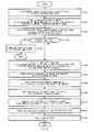
- Figs. 3 and 4 are flow charts describing the operation of the electronic camera 10. Referring to the step numbers shown in Fig. 3 , the operation will be described below.
- Step S1 Upon activation of the main power source of the electronic camera 10, the microprocessor 19 instructs the imaging control section 14 to read out low resolution images.
- the imaging control section 14 drives the imaging sensor 11 with the low resolution read-out mode, and sequentially reads out low resolution images at 30 frames/second, for example, as shown in Fig. 5 .
- Step S2 The low resolution images read out from the imaging sensor 11 are temporarily stored in the memory 17 after having been processed via the signal processing section 15 and the A/D converter 16. Meanwhile, the microprocessor 19 deletes the low resolution images, which have exceeded a predefined number of frames in the memory 17, in order from the oldest one.
- the predefined number of frames mentioned here corresponds to the number of frames of the low resolution images used for composing relocated images described below, and is preferably set equal to or larger than the (number of pixels of the high resolution image/number of pixels of the low resolution image).
- Step S3 The monitor display section 30 displays the low resolution images (through images) on the monitor screen.
- the microprocessor 19 calculates the exposure based on photometry result of the photometry section (not shown) or brightness of the low resolution images, and judges the exposure time of the high resolution image.
- Step S4 Here, the microprocessor 19 judges whether or not the release button is fully pressed by the user.
- step S5 When the release button is fully pressed, the microprocessor 19 shifts the operation to step S5. On the other hand, when the release button is not fully pressed, the microprocessor 19 returns the operation to step S1.
- Step S5 Here, the microprocessor 19 judges whether or not the exposure time setting of the high resolution image determined in step S3 is equal to or shorter than a tolerable upper limit within which blurring is not outstanding.
- the tolerable upper limit is set around 1 / (focal length in terms of 35mm size of imaging lens 12) second.
- the microprocessor 19 shifts the operation to step S6.
- the microprocessor 19 shifts the operation to step S7.
- Step S6 The imaging control section 14 shutter-controls the imaging sensor 11 in accordance with the set exposure time. Subsequently, the imaging control section 14 drives the imaging sensor 11 with a high resolution read out mode and reads out the high resolution image.
- the high resolution image (still image) is recorded in a recording medium 22a after having gone through image processing and image compression as with the prior art. After this operation, the electronic camera 10 completes the imaging operation.
- Step S7 When, on the other hand, it is judged that the exposure time setting exceeds the tolerable upper limit of blurring, the microprocessor 19 limits the exposure time to be equal to or shorter than the tolerable upper limit within which blurring does not occur.
- the imaging control section 14 shutter-controls the imaging sensor 11 in accordance with exposure time which has been limited to be short. In such a condition, the imaging control section 14 drives the imaging sensor 11 with a high resolution read-out mode, and reads out a high resolution image. Although this high resolution image has a low signal level caused by underexposure, it is an image with little possibility of blurring. The high resolution image is temporarily recorded in the memory 17.
- Step S8 The gain correcting section 31 in the image processing device 25 reads the high resolution image from the memory 17. By adjusting the gain of the high resolution image, the gain correcting section 31 adjusts its signal level to that of the low resolution images.
- Step S9 The reduced image creating section 32 converts the resolution of the high resolution image after gain adjusting, and adjusts the number of pixels to that of the low resolution images.
- the number of vertical and horizontal pixels of the high resolution image can be respectively reduced to a resolution conversion of 1 /4, by extracting the mean value of 4x4 pixels.
- a high resolution image which has been converted to low resolution (hereafter referred to as a reduced image) is transmitted to the feature quantity extracting section 35.
- Step S10 Fig. 6 is a view describing detection of image discrepancy by comparing projection edges. Referring to Fig. 6 , processing of image discrepancy detection will be described below.
- the feature quantity extracting section 35 extracts vertical edge components g y from the reduced image f (x, y) using a filter for extracting vertical edges (refer to Fig. 6[A] ) represented by the following equation.
- g y x y - f ⁇ x , y - 1 + f ⁇ x , y + 1
- the feature quantity extracting section 35 extracts horizontal edge components g x from the reduced image f (x, y) using a filter for extracting horizontal edges (refer to Fig. 6[B] ) represented by the following equation.
- the feature quantity extracting -section 35 substitutes zero for the vertical edge -components g y and horizontal edge components g x that falls within a predefined small amplitude.
- the feature quantity extracting section 35 calculates the vertical projection wave form by performing cumulative addition of the vertical edge components g y for a unit of horizontal row.
- the feature quantity extracting section 35 calculates, as shown in Fig. 6[B] , the horizontal projection wave form by performing cumulative addition of the horizontal edge components g x for a unit of vertical column.
- the feature quantity extracting section 39 reads a plurality of low resolution images from the memory 17.
- the feature quantity extracting section 39 performs the same processing as that of the feature quantity extracting section 35 on individual low resolution images, and calculates the vertical projection wave form and the horizontal projection wave form respectively.
- the rough detecting section 36 obtains the difference therebetween and detects the wave form discrepancy that provides the minimum absolute value of the sum of the difference, as shown in Fig. 6[A] .
- the wave form discrepancy is equivalent to the position discrepancy in the vertical direction of the reduced image and the low resolution images.
- the rough detecting section 36 obtains the difference therebetween and detects the wave form discrepancy that provides the minimum absolute value of the sum of the difference.
- the wave form discrepancy is equivalent to the position discrepancy in the horizontal direction of the reduced image and the low resolution images.
- the rough detecting section 36 obtains the position discrepancy (rough detection result) of a plurality of low resolution images, respectively, with the reduced image as the position reference, and outputs the position discrepancy to the detail detecting section 38.
- Step S11 The feature quantity extracting section 33 reads the gain-compensated high resolution image and extracts vertical edge components g y and horizontal edge components g x , using the edge extraction filter.
- the extraction filter is switched as described below according to the read out system of the low resolution images.
- the feature quantity extracting section 33 calculates the vertical projection wave form by performing cumulative addition of the vertical edge components g y for a unit of horizontal row. Additionally, the feature quantity extracting section 33 calculates the horizontal projection wave form by performing cumulative addition of the horizontal edge components g x for a unit of vertical column.
- the phase dividing section 37 performs sub-sampling in every four pixels of the vertical projection wave form of the high resolution image.
- the phase dividing section 37 generates four types of mutually phase-shifted sampling information as shown in Fig. 7 by shifting phases of sub-sampling.
- the phase dividing section 37 performs sub-sampling in every four pixels of the horizontal projection wave form of the high resolution image. In this occasion, the phase dividing section 37 generates four types of mutually phase-shifted sampling information by shifting phases of sub-sampling.
- Step S12 By shifting the sampling information of the vertical projection wave form obtained from the high resolution image and the vertical projection wave form of the low resolution images, with the detection result of the position discrepancy detected by the rough detecting section 36 as the starting point, the detail detecting section 38 obtains the difference therebetween and detects the wave form discrepancy that provides the minimum absolute value of the sum of the difference.
- the detail detecting section 38 finds the-wave form discrepancy with which feature of the patterns (wave form, here) best coincides, by detecting the wave form discrepancy for each of the four types of sampling information.
- the wave form discrepancy corresponds to the position discrepancy of the horizontal direction in units smaller than pixel distances of the low resolution images.
- the detail detecting section 38 similarly detects the vertical position discrepancy in units smaller than pixel distances of the low resolution images (for example, a unit of pixel distance of the high resolution image).
- the detail detecting section 38 finds the position discrepancy (detail detection result) of a plurality of low resolution images, respectively, with the high resolution image as the position reference, and outputs the position discrepancy to the image composition section 34.
- Step S13 The image composition section 34 performs high-pass filtering on the low resolution images and calculates the absolute value of the sum of the filtering result to find the amount of high frequency components. According to the amount of the found high frequency component, a plurality of low resolution images are sorted.
- the images from the high order to predetermined order may be discriminated while imparting order to images in descending order of the amount of high frequency components, and those may be images to be used for composition.
- images having an amount of high frequency components exceeding a predefined threshold value may be selected as the images to be used for composition.
- Step S14 The image composition section 34 performs high-pass filtering on a high resolution image and divides the high resolution image into an edge region and a flat region according to the result of filtering.
- Step S15 In the edge region obtained in step S14, the composite rate is lowered progressively for images having less high frequency components. On the other hand, in the flat region obtained in step S14, the composite rate of an image having less high frequency components is raised to be higher than the edge part. Meanwhile, for a region which is neither an edge region nor a flat region, provided is an intermediate composite rate of both regions.
- Step S16 The image composition section 34 magnifies (4x4 times) a plurality of low resolution images respectively. In this occasion, the image composition section 34 obtains a magnified image with a widened pixel distance, without performing pixel interpolation.
- the image composition section 34 performs mapping (relocation) as shown in Fig. 9 by shifting the pixel positions of the magnified image of the low resolution images respectively based on the detail detection result of the position discrepancy obtained by the detail detecting section 38.
- Step S17 In the relocated images after having been completed the mapping processing, there are pixels having unfilled gaps, pixels displaced from the normal pixel position, and overlapping pixels.
- the image composition section 34 picks up neighboring pixels for each normal pixel position of the relocated images.
- the image composition section 34 executes a weighted averaging on the signal components of these neighboring pixels, in accordance with the composite rate which has been set in step S15.
- the image composition section 34 sets the value of the weighted average to the signal components (luminance/color difference component, etc.) of the normal pixel position.
- the relocated images may be composed by calculating the median of signal components of neighboring pixels.
- Step S18 The image composition section 34 executes filtering on the luminance components of the high resolution image as described below.
- the image composition section 34 extracts luminance components from the high resolution image after gain correction, and performs filtering which is a combination of median calculation and Gaussian filtering.
- the filter size may be set to 3x3 pixels, and three middle values are extracted from the nine pixels in the filter size to perform Gaussian filtering. With this processing, noise portion included in underexposed luminance components can be preliminarily reduced.
- Step S19 Next, composite rate is set between luminance components A of the high resolution image after filtering and luminance components B of the relocated images.
- Gaussian filter for calculating the luminance components g (i, j) of composite image.
- Gaussian filtering smoothing
- the luminance components A of the high resolution image are locally prioritized at portions where patterns are largely different between the high resolution image and the relocated images.
- the composite rate G (i,j,p) is not particularly changed depending on the reference distance of pixels.
- luminance components B within the filter size m can be reflected in the luminance components A, even if the reference distance is far.
- mis-positioning of the relocated images can be tolerated to a certain extent.
- ⁇ in the above equation is a numeric value for adjusting the value of the composite rate or the range of reduction.
- the composite rate of the relocated images locally decreases in the vicinity of edges of the high resolution image, by reducing ⁇ locally. As a result, effects (smoothing and distortion) on the image structure such as edges can be suppressed.
- ⁇ in the above equation is progressively set larger when time interval and/or position discrepancy between the high resolution image and the low resolution images becomes smaller.
- the composite rate of the relocated images is generally raised progressively, if patterns of the high resolution image and the low resolution images are estimated to be closer, by allowing ⁇ to be varied.
- information of the relocated images (low resolution images) having closer patterns can be reflected in the composite image with a higher priority.
- Step S20 The color difference components of the relocated images generated in step S17 and the luminance components of the composite image generated in step S19 are combined to generate a high resolution color image having information of the low resolution images reflected therein.
- This color image is recorded in the recording medium 22a via the image compression section 24 and the recording section 22, or the like.
- the present embodiment effectively uses the through images (low resolution images), which will be discarded after being displayed on the monitor, for enhancing image quality of the still image (high resolution image).
- image quality of the still image high resolution image.
- positioning of a plurality of low resolution images is performed, with the high resolution image having a high pixel density as the position reference. Therefore, precision of the pattern positioning of low resolution images is high, whereby a better image composition result can be obtained.
- a plurality of sampling information with mutually shifted sampling phases is generated from the high resolution image.
- Position discrepancy can be detected in units smaller than pixel distances of the low resolution images by detecting position discrepancy between the sampling information and the low resolution images, respectively. Therefore, precision of pattern positioning of the low resolution images can be further raised, whereby a still better image composition result can be obtained.
- luminance components of a higher resolution than the low resolution images can be obtained by positioning and mapping the luminance components (signal components of high visual sensitivity) of a plurality of low resolution images.
- color difference components having a higher resolution than the low resolution images can also be obtained by positioning and mapping the color difference components (signal components of low visual sensitivity) of a plurality of low resolution images.
- the high resolution luminance components (relocated images) generated by positioning are composed with a weight with the luminance components of the original high resolution image.
- luminance noise having no correlation between both images can be suppressed.
- S/N of the high resolution image in an underexposed condition see step S7) can be improved.
- the composite rate of the relocated images is locally reduced when the signal difference between the high resolution image and the relocated images is significantly large.
- the signal difference between both images significantly widens and the composite rate of the relocated images decreases. Therefore, the mis-positioning will not be significantly reflected in the image composition result.
- the composite rate of the relocated images is locally reduced at portions where a larger local signal variation of the high resolution image exists. Therefore, the image structure of the high resolution image is given a higher priority, in the edge part of the image or the like. As a result, adverse effects such that an edge seems to have multiple lines can be avoided.
- the composite rate of the relocated images is generally raised.
- a plurality of low resolution images are sorted in the order of the amount of high frequency components of spatial frequency.
- images having less high frequency components caused by outstanding blurring are excluded from the images to be used for composition.
- the composite rate of the flat part is increased in comparison with the edge part for images which are judged to have less high frequency components.
- positioning composition of a plurality of images is performed more uniformly in the flat part, whereby image S/N after the positioning composition can be raised.
- Fig. 10 is a flow chart describing the operation of the electronic camera 10 in the second embodiment.
- Fig. 11 is a schematic view showing the composition processing of an image in the second embodiment.
- the second embodiment is a modified example of the first embodiment, wherein the electronic camera composes a plurality of images with the same resolution.
- the configuration of the electronic camera in the second embodiment is common to the electronic camera of the first embodiment ( Fig. 1 ), duplicative description is omitted.
- steps S101 to S103 of Fig. 10 correspond to S1 to S3 of Fig. 3 , respectively, duplicate description is omitted. Operation of the electronic camera will be described below, along the step numbers shown in Fig. 10 .
- Step S104 Here, the microprocessor 19 judges whether or not the exposure time setting of the high resolution image determined in step S103 is equal to or shorter than the tolerable upper limit within which blurring is not outstanding. Meanwhile, the tolerable upper limit is set in the same way as the above step S5.
- the microprocessor 19 shifts the operation to step S105.
- the microprocessor 19 shifts the operation to step S106.
- Step S105 The imaging control section 14, shutter-controls the imaging sensor 11 in accordance with exposure time being set, and images a high resolution image (still image). Meanwhile, since the operation of this step corresponds to step S6, duplicate description is omitted.
- Step S106 On the other hand, when it is judged that the exposure time setting exceeds the tolerable upper limit of blurring, the microprocessor 19 switches the operation state of the electronic camera to a consecutive imaging mode. Then, the microprocessor 19 limits the exposure time of each frame in the consecutive imaging mode to be shorter than the tolerable upper limit within which blurring does not occur.
- the imaging control section 14 in the consecutive imaging mode drives the imaging sensor 11 in high resolution read-out mode in accordance with the exposure time limited to be short. In this manner, a plurality of high resolution images will be consecutively imaged by the imaging sensor 11. Although respective high resolution images have a low signal level caused by underexposure, they are images with little possibility of blurring. The above-mentioned high resolution images are temporarily recorded in the memory 17 respectively.
- imaging will be performed in accordance with the following (1) or (2), for example.
- the microprocessor 19 specifies an image which corresponds to the timing of the above-mentioned instruction as being the reference image, among the high resolution images in the memory 17.
- the microprocessor 19 specifies a predefined number of continual high resolution images in the time axis direction for the reference image, as targets of composition processing described below.
- a high resolution image specified as the target of composition processing is referred to as an image to be composed.
- the reference image and the images to be composed are kept in the memory 17 at least until the composition processing is completed.
- the microprocessor 19 displays the imaged images on the monitor display section 30 respectively, and causes the user to select a reference image. Then, the microprocessor 19 sets an image specified by the user among the high resolution images which have been consecutively imaged to the recording image. In addition, the microprocessor 19 sets images other than the reference image among the high resolution images which have been consecutively imaged to the images to be composed.
- the microprocessor 19 may specify an image corresponding to the timing of the instruction that starts the consecutive imaging (the high resolution image imaged first) as the reference image, in case (2). In this case, it is possible to omit the process of letting the user specify the reference image.
- Step S107 The image processing device 25 detects discrepancy of the images to be composed (S106) relative to the reference image (S106) by the same processing as step S10 of the first embodiment. Meanwhile, detection of such image discrepancy is performed on all of the images to be composed.
- Step S108 The image composition section 34 of the image processing device 25 performs high-pass filtering on the images to be composed (S106), and calculates the absolute value of the sum of the result of filtering to find the amount of high frequency components. Then, the image composition section 34 sorts a plurality of the images to be composed in accordance with the found amount of high frequency components.
- the image composition section 34 may discriminate the images from the high order to predetermined order while imparting order to images in descending order of the amount of high frequency components, to narrow down the images which will be actually used for composition from among the images to be composed.
- the image composition section 34 may select images having an amount of high frequency components exceeding a predefined threshold value to narrow down the images to be composed to those which will be actually used for composition.
- Step S109 The image composition section 34 performs high-pass filtering on the reference image, and region-divides the reference image into an edge region and a flat region based on the result of filtering. Then, the image composition section 34 progressively minimizes the composite rate of images to be composed having less high frequency components, in the edge region of the reference image. On the other hand, the image composition section 34 raises the composite rate of images having less high frequency components in the flat region of the reference image than the edge part. Meanwhile, for region which is neither an edge region nor a flat region, an intermediate composite rate of both regions is set.
- Step S110 The image composition section 34 performs mapping (relocation) by displacing the pixel positions of the images to be composed respectively (referring to Fig. 11 ), based on the detection result of position discrepancy obtained in S107, with the reference image as the position reference.
- mapping mapping
- the group of relocated images is treated as three dimensional images having a time axis t in addition to x axis and y axis which indicate the position within the same image.
- Step S111 The image composition section 34 performs a composition processing of the reference image (S106) and the relocated images (S110) to generate the final composite image.
- the image composition section 34 sequentially composes respective relocated images for the reference image, repeating the composition processing as many times as the number of the relocated images. Meanwhile, the image composition section 34 may preliminarily compose a plurality of relocated images by median calculation or the like, then compose the preliminarily composed relocated images with the reference image.
- the image composition section 34 reads out the initial value of the composite rate obtained in S109. Then, the image composition section 34 further adjusts the composite rate of the reference image and the relocated images, while paying attention to the gradation value of the reference image and the gradation value of the relocated images.
- the image composition section 34 when difference of gradation values between a target pixel of the reference image and a target pixel of the relocated image is equal to or larger than a threshold value (case of a large gradation difference), the image composition section 34 locally reduces the composite rate at the target pixel.
- a threshold value case of a large gradation difference
- the image composition section 34 when difference of gradation values between a target pixel of the reference image and a target pixel of the relocated image is smaller than a threshold value (case of small gradation difference), the image composition section 34 locally raises the composite rate at the target pixel. In this manner, adverse effects caused by mis-positioning between the images can be significantly suppressed.
- the image composition section 34 adjusts the composite rate in accordance with the local signal variation on the reference image. For example, the image composition section 34 locally reduces progressively the composite rate for the relocated images at portions where a larger local signal variation on the reference image exists. In addition, the image composition section 34 locally raises the composite rate for the relocated images at portions where the local signal variation on the reference image is small. In this manner, adverse effects such that an edge on the composite image seems to have multiple lines can be suppressed.
- the image composition section 34 composes the reference image and the relocated images by adding respective pixels corresponding thereto, in accordance with the composite rate. It is assumed in S111 that the image composition section 34 finds the luminance components and the color difference components of each pixel respectively in the composition processing. In this manner, a high resolution color image will be generated, having information of a plurality of images to be composed reflected therein.
- Step S112 The microprocessor 19 records the final composite image (generated in S111) in the recording medium 22a, via the image compression section 24 and the recording section 22 or-the like. Description of Fig. 10 has thus been completed.
- the configuration of the second embodiment can also achieve a similar effect as with the first embodiment. Particularly, since the resolution of the relocated images is high with a large amount of information in the second embodiment, a further fine color image can be obtained.
- the user when performing the image processing of the second embodiment on the computer, the user can specify any image among those which have been consecutively imaged as the reference image.
- the present invention is a technique available for image processing devices.
Landscapes
- Engineering & Computer Science (AREA)
- Multimedia (AREA)
- Signal Processing (AREA)
- Computing Systems (AREA)
- Theoretical Computer Science (AREA)
- Image Processing (AREA)
- Studio Devices (AREA)
Abstract
Description
- The present invention relates to an image processing device, an electronic camera and an image processing program.
- Previously, a technique has been known which restores blurring of a picked up image by performing divided exposures for a plurality of times using the same electronic camera, and positioning and composing the plurality of obtained images (refer to, for example,
patent document 1 below). Pattern matching, block matching, or the like are known as a processing to detect such position discrepancy of multiple images. - The following
patent document 2 is known as a technique of detecting position discrepancy of patterns between images which have been output from separate imaging sensors having different resolutions. This prior art technique first performs a global search between a high resolution image and low resolution images to find candidates of a coincide region. The technique then performs pixel interpolation on both images respectively, in the coincide region to find a region in which the patterns coincide in detail by -comparison between interpolated pixels. With such a two-phase search processing, position discrepancy is detected between images having different resolutions. - Patent Document 1: Japanese Unexamined Patent Application Publication No.
2002-107787 - Patent Document 2:
WO 95/04329 - With the prior-art technique, a high resolution still image must be read out over a plurality of times as a result of divided exposure. In this case, since the frame rate of the still image is generally low, time intervals between the images tend to significantly widen. For a moving object, accordingly, the degree of coincidence of patterns among multiple images becomes lower, making it difficult to perform a good image composition.
- Meanwhile, low resolution images can be read out in a high frame rate if using a low resolution read-out mode (draft mode) of imaging sensors. In this case, time intervals between the images can be shortened. However, precision of detecting position discrepancy of patterns between low resolution images is rough. Therefore, the patterns can be easily distorted as being such that an edge part between images is slightly displaced, when a pattern is positioned in accordance with a low-precision position discrepancy. As a result, it is also difficult to perform a good image composition by this method.
- Additionally, in the prior-art technique, adverse effects caused by position discrepancy of a plurality of images are concerned, as being such that an edge part of a pattern results in multiple lines after composition, or an edge being blurred after composition.
- The present invention therefore solves one or more of the above-mentioned problems. One of the propositions of the invention is to provide a technique for performing a good image composition.
- Additional, one of the propositions of the invention is to provide a technique for reducing the adverse effects of mis-positioning in the positioning composition of a plurality of images.
-
- <1> The image processing device according to a first aspect of the present invention is provided with an image input section, a position discrepancy detecting section, and an image composing section. The image input section reads a plurality of low resolution images with a same object imaged and at least one high resolution image with the same object imaged. The position discrepancy detecting section detects position discrepancy of patterns between respective low resolution images and the high resolution image. The image composition section positions and composes patterns of the plurality of low resolution images based on the position discrepancy.
-
- <2> Preferably, the position discrepancy detecting section is provided with a phase dividing section, and a detail detecting section. The phase dividing section generates a plurality of pieces of mutually phase-shifted sampling information, by performing sub-sampling of the high resolution image or its feature while shifting phases. The detail detecting section detects position discrepancy in smaller unit than pixel distances of the low resolution images by detecting position discrepancy where a feature of patterns best coincides between the low resolution images and the plurality of pieces of sampling information.
-
- <3> Preferably, in addition, the position discrepancy detecting section is provided with a rough detecting section and a detail detecting section. The rough detecting section detects position discrepancy of patterns between a plurality of low resolution images. The detail detecting section detects position discrepancy between the high resolution image and the low resolution images starting from the position discrepancy detected by the rough detecting section.
-
- <4> Preferably, the Image composition section relocates and composes signal components of the plurality of low resolution images based on the position discrepancy, and generates relocated images having higher resolution.
-
- <5> Preferably, in addition, the image composition section generates a composite image based on the high resolution image and the relocated images.
-
- <6> Preferably, the composite image is generated with the composite rate of the relocated images locally reduced progressively at portions where a larger signal difference exists between the high resolution image and the relocated images.
-
- <7> Preferably, the composite image is generated with the composite rate of the relocated images locally reduced progressively at portions where a larger local signal variation of the high resolution image exists.
-
- <8> Preferably, the composite image is generated with the composite rate of the relocated images being generally raised progressively when the time interval and/or position discrepancy between the high resolution image and the low resolution images is smaller.
-
- <9> Preferably, the Image composition section generates the composite image for high visual-sensitivity signal components constituting a color image, whereas the image composition section generates relocated images for the remaining low visual-sensitivity signal components.
-
- <10> The image processing device according to a second aspect of the present invention is provided with an image input section, a position discrepancy detecting section, and an image composition section. The image input section reads a plurality of images with the same object imaged. The position discrepancy detecting section detects position discrepancy of patterns between the plurality of images. The image composition section positions and composes the patterns of the plurality of images based on the position discrepancy. In the above-mentioned configuration, the image composition section judges, among a plurality of images, the magnitude of local signal variation for an image which has been preliminarily set as the reference of positioning. The image composition section makes an adjustment so as to locally lower the composite rate of other images at portions where the signal variation is judged to be large.
-
- <11> The image processing device according to a third aspect of the present invention is provided with an image input section, a position discrepancy detecting section, and an image composition section. The image input section reads a plurality of images with the same object imaged. The position discrepancy detecting section detects position discrepancy of patterns between the plurality of images. The image composition section positions and composes the patterns of the plurality of images based on the position discrepancy. In the above-mentioned configuration, the image composition section finds the difference of gradation value of the target pixels at respective corresponding positions in the positioning reference image and other images. The image composition section makes an adjustment so as to locally lower the composite rate of other images at portions where the difference of gradation value is judged to be large.
-
- <12> The electronic camera according to the first aspect of the present invention is provided with the image processing device described in any one of the above-mentioned <1> to <9>, and an imaging section which images the images of an object with at least two levels of resolution. In this case, a high resolution image processed by the image processing device is taken to be a high resolution still image imaged with the imaging section. On the other hand, a low resolution image processed by the image processing device is taken to be a low resolution image imaged with the imaging section before and/or after imaging the still image.
-
- <13> The electronic camera according to the second aspect of the present invention is provided with the image processing device described in the above <10> or <11>, and the imaging section which consecutively images the images of an object and generates a plurality of images, the electronic camera having a function of positioning and composing a plurality of images using the image processing device.
-
- <14> The image processing program of the present invention is a program which causes the computer to function as the image processing device described in any one of the above-mentioned <1> to <11>.
- In one aspect of the present invention, low resolution images having a high frame rate are composed. Therefore, the degree of coincidence of patterns among images increases, thereby enabling a better image composition.
- Furthermore, in one aspect of the present invention, position discrepancy corresponding to each of a plurality of low resolution images is detected, using a high resolution image with a high pixel density as the position reference. Therefore, relative position discrepancy of the low resolution images can be detected with a high precision. As a result, positioning precision of the patterns of the low resolution images is high, thereby a better image composition becomes possible.
- Additionally, in another aspect of the present invention, the composite rate of the images, which is positioned at portions where signal variation of the positioning reference image is large or portions where gradation difference between the images is large, locally decreases. Therefore, distortion of image structure caused by mis-positioning can be suppressed.
-
-
Fig. 1 is a block diagram showing the electronic camera 10 (including the image processing device 25). -
Fig. 2 is a block diagram schematically showing a configuration of theimage processing device 25. -
Fig. 3 is a flow chart describing the operation of theelectronic camera 10 in the first embodiment. -
Fig. 4 is a flow chart describing the operation of theelectronic camera 10 in the first embodiment. -
Fig. 5 is an explanatory view of low resolution images and a high resolution image. -
Fig. 6 illustrates how image discrepancy is detected by comparing projection edges. -
Fig. 7 illustrates how sub-sampling is performed. -
Fig. 8 illustrates the adjustment operation of composite rate. -
Fig. 9 is an explanatory view of the operation of generating relocated images. -
Fig. 10 is a flow chart describing the operation of theelectronic camera 10 in the second embodiment. -
Fig. 11 is a schematic view showing the image composition processing in the second embodiment. -
Fig. 1 is a block diagram showing an electronic camera 10 (including image processing device 25) of the present embodiment. - In
Fig. 1 , theelectronic camera 10 has animaging lens 12 equipped therein. The imaging surface of an imaging sensor 11 is provided in the image space of theimaging lens 12. The imaging sensor 11 is controlled by an imaging control section 14. The imaging sensor 11 is provided with a mode of reading high resolution images and a mode of reading low resolution images by thinning or adding pixels within the element. The image signal output from the imaging sensor 11 is temporarily stored in amemory 17 after being processed by a signal processing section 15 and an analog-to-digital conversion part 16. - The
memory 17 is coupled to abus 18. -An imaging control section 14, amicroprocessor 19, arecording section 22, animage compression section 24, amonitor display section 30, and animage processing device 25 are also coupled to thebus 18. An operation section 19a such as a release buttons is coupled to the above-mentionedmicroprocessor 19. In addition, arecording medium 22a is detachably mounted on therecording section 22. -
Fig. 2 is a block diagram schematically showing a configuration of theimage processing device 25. - The high resolution image read out from the
memory 17 is supplied to a reducedimage creating section 32, a featurequantity extracting section 33, and animage composition section 34, respectively via again correcting section 31. Output data of the reducedimage creating section 32 is supplied to the rough detectingsection 36 via a featurequantity extracting section 35. Output data of the featurequantity extracting section 33 is supplied to adetail detecting section 38 via aphase dividing section 37. - On the other hand, a plurality of low resolution images read out from the
memory 17 are supplied to a featurequantity extracting section 39 and theimage composition section 34,respectively. Output data of the featurequantity extracting section 39 is supplied to the rough detectingsection 36 and adetail detecting section 38, respectively. - The position discrepancy which is roughly detected in the rough detecting
section 36 is supplied to thedetail detecting section 38. The position discrepancy which is detected with a high precision in the detail-detectingsection 38 is supplied-to theimage composition section 34. Based on the detection result of the position discrepancy, theimage composition section 34 composes a plurality of low resolution images and high resolution images. -
Figs. 3 and4 are flow charts describing the operation of theelectronic camera 10. Referring to the step numbers shown inFig. 3 , the operation will be described below. - Step S1: Upon activation of the main power source of the
electronic camera 10, themicroprocessor 19 instructs the imaging control section 14 to read out low resolution images. The imaging control section 14 drives the imaging sensor 11 with the low resolution read-out mode, and sequentially reads out low resolution images at 30 frames/second, for example, as shown inFig. 5 . - Step S2: The low resolution images read out from the imaging sensor 11 are temporarily stored in the
memory 17 after having been processed via the signal processing section 15 and the A/D converter 16. Meanwhile, themicroprocessor 19 deletes the low resolution images, which have exceeded a predefined number of frames in thememory 17, in order from the oldest one. - The predefined number of frames mentioned here corresponds to the number of frames of the low resolution images used for composing relocated images described below, and is preferably set equal to or larger than the (number of pixels of the high resolution image/number of pixels of the low resolution image).
- For example, when the number of vertical and horizontal pixels of the low resolution images are respectively set to be 1 /4 of the number of vertical and horizontal pixels of the high resolution image, it is preferable to set the predefined number of frames equal to or larger than 4x4=16.
- Step S3: The
monitor display section 30 displays the low resolution images (through images) on the monitor screen. On the other hand, themicroprocessor 19 calculates the exposure based on photometry result of the photometry section (not shown) or brightness of the low resolution images, and judges the exposure time of the high resolution image. - Step S4: Here, the
microprocessor 19 judges whether or not the release button is fully pressed by the user. - When the release button is fully pressed, the
microprocessor 19 shifts the operation to step S5. On the other hand, when the release button is not fully pressed, themicroprocessor 19 returns the operation to step S1. - Step S5: Here, the
microprocessor 19 judges whether or not the exposure time setting of the high resolution image determined in step S3 is equal to or shorter than a tolerable upper limit within which blurring is not outstanding. For example, the tolerable upper limit is set around 1 / (focal length in terms of 35mm size of imaging lens 12) second. - When the exposure time setting is equal to or shorter than the tolerable upper limit, the
microprocessor 19 shifts the operation to step S6. On the other hand, when the exposure time setting exceeds the tolerable upper limit, themicroprocessor 19 shifts the operation to step S7. - Step S6: The imaging control section 14 shutter-controls the imaging sensor 11 in accordance with the set exposure time. Subsequently, the imaging control section 14 drives the imaging sensor 11 with a high resolution read out mode and reads out the high resolution image. The high resolution image (still image) is recorded in a
recording medium 22a after having gone through image processing and image compression as with the prior art. After this operation, theelectronic camera 10 completes the imaging operation. - Step S7: When, on the other hand, it is judged that the exposure time setting exceeds the tolerable upper limit of blurring, the
microprocessor 19 limits the exposure time to be equal to or shorter than the tolerable upper limit within which blurring does not occur. - The imaging control section 14, shutter-controls the imaging sensor 11 in accordance with exposure time which has been limited to be short. In such a condition, the imaging control section 14 drives the imaging sensor 11 with a high resolution read-out mode, and reads out a high resolution image. Although this high resolution image has a low signal level caused by underexposure, it is an image with little possibility of blurring. The high resolution image is temporarily recorded in the
memory 17. - Step S8: The
gain correcting section 31 in theimage processing device 25 reads the high resolution image from thememory 17. By adjusting the gain of the high resolution image, thegain correcting section 31 adjusts its signal level to that of the low resolution images. - Step S9: The reduced
image creating section 32 converts the resolution of the high resolution image after gain adjusting, and adjusts the number of pixels to that of the low resolution images. - For example, the number of vertical and horizontal pixels of the high resolution image can be respectively reduced to a resolution conversion of 1 /4, by extracting the mean value of 4x4 pixels.
- Thus, a high resolution image which has been converted to low resolution (hereafter referred to as a reduced image) is transmitted to the feature
quantity extracting section 35. - Step S10:
Fig. 6 is a view describing detection of image discrepancy by comparing projection edges. Referring toFig. 6 , processing of image discrepancy detection will be described below. - First, the feature
quantity extracting section 35 extracts vertical edge components gy from the reduced image f (x, y) using a filter for extracting vertical edges (refer toFig. 6[A] ) represented by the following equation.
quantity extracting section 35 extracts horizontal edge components gx from the reduced image f (x, y) using a filter for extracting horizontal edges (refer toFig. 6[B] ) represented by the following equation.
section 35 substitutes zero for the vertical edge -components gy and horizontal edge components gx that falls within a predefined small amplitude. - Next, as shown in
Fig. 6[A] , the featurequantity extracting section 35 calculates the vertical projection wave form by performing cumulative addition of the vertical edge components gy for a unit of horizontal row. - Furthermore, the feature
quantity extracting section 35 calculates, as shown inFig. 6[B] , the horizontal projection wave form by performing cumulative addition of the horizontal edge components gx for a unit of vertical column. - On the other hand, the feature
quantity extracting section 39 reads a plurality of low resolution images from thememory 17. The featurequantity extracting section 39 performs the same processing as that of the featurequantity extracting section 35 on individual low resolution images, and calculates the vertical projection wave form and the horizontal projection wave form respectively. - Here, by shifting the vertical projection wave form of the central region of the reduced image and the vertical projection wave form of the central region of the low resolution images, the rough detecting
section 36 obtains the difference therebetween and detects the wave form discrepancy that provides the minimum absolute value of the sum of the difference, as shown inFig. 6[A] . The wave form discrepancy is equivalent to the position discrepancy in the vertical direction of the reduced image and the low resolution images. - Additionally, as shown in
Fig. 6[B] , by shifting the horizontal projection wave form of the central region of the reduced image and the horizontal projection wave form of the central region of the low resolution images, the rough detectingsection 36 obtains the difference therebetween and detects the wave form discrepancy that provides the minimum absolute value of the sum of the difference. The wave form discrepancy is equivalent to the position discrepancy in the horizontal direction of the reduced image and the low resolution images. - In this manner, the rough detecting
section 36 obtains the position discrepancy (rough detection result) of a plurality of low resolution images, respectively, with the reduced image as the position reference, and outputs the position discrepancy to thedetail detecting section 38. - Step S11: The feature
quantity extracting section 33 reads the gain-compensated high resolution image and extracts vertical edge components gy and horizontal edge components gx, using the edge extraction filter. - Here, it is preferred that the extraction filter is switched as described below according to the read out system of the low resolution images.
- * when the low resolution images are generated by adding or averaging pixels


- * when low resolution images are generated by thinning for pixels


- Next, the feature
quantity extracting section 33 calculates the vertical projection wave form by performing cumulative addition of the vertical edge components gy for a unit of horizontal row. Additionally, the featurequantity extracting section 33 calculates the horizontal projection wave form by performing cumulative addition of the horizontal edge components gx for a unit of vertical column. - The
phase dividing section 37 performs sub-sampling in every four pixels of the vertical projection wave form of the high resolution image. Thephase dividing section 37 generates four types of mutually phase-shifted sampling information as shown inFig. 7 by shifting phases of sub-sampling. - Similarly, the
phase dividing section 37 performs sub-sampling in every four pixels of the horizontal projection wave form of the high resolution image. In this occasion, thephase dividing section 37 generates four types of mutually phase-shifted sampling information by shifting phases of sub-sampling. - Step S12: By shifting the sampling information of the vertical projection wave form obtained from the high resolution image and the vertical projection wave form of the low resolution images, with the detection result of the position discrepancy detected by the rough detecting
section 36 as the starting point, thedetail detecting section 38 obtains the difference therebetween and detects the wave form discrepancy that provides the minimum absolute value of the sum of the difference. - The
detail detecting section 38 finds the-wave form discrepancy with which feature of the patterns (wave form, here) best coincides, by detecting the wave form discrepancy for each of the four types of sampling information. The wave form discrepancy corresponds to the position discrepancy of the horizontal direction in units smaller than pixel distances of the low resolution images. - Furthermore, the
detail detecting section 38 similarly detects the vertical position discrepancy in units smaller than pixel distances of the low resolution images (for example, a unit of pixel distance of the high resolution image). - In this manner, the
detail detecting section 38 finds the position discrepancy (detail detection result) of a plurality of low resolution images, respectively, with the high resolution image as the position reference, and outputs the position discrepancy to theimage composition section 34. - Step S13: The
image composition section 34 performs high-pass filtering on the low resolution images and calculates the absolute value of the sum of the filtering result to find the amount of high frequency components. According to the amount of the found high frequency component, a plurality of low resolution images are sorted. - Meanwhile, as shown in
Fig. 8 , the images from the high order to predetermined order may be discriminated while imparting order to images in descending order of the amount of high frequency components, and those may be images to be used for composition.
In addition, images having an amount of high frequency components exceeding a predefined threshold value may be selected as the images to be used for composition. - With such discrimination processing, images whose high frequency components do not satisfy the criterion caused by a large amount of blurring quantity, or the like, can be suitably excluded from the composition processing. As a result, quality of the image after composition can certainly be enhanced.
- Step S14: The
image composition section 34 performs high-pass filtering on a high resolution image and divides the high resolution image into an edge region and a flat region according to the result of filtering. - Step S15: In the edge region obtained in step S14, the composite rate is lowered progressively for images having less high frequency components. On the other hand, in the flat region obtained in step S14, the composite rate of an image having less high frequency components is raised to be higher than the edge part. Meanwhile, for a region which is neither an edge region nor a flat region, provided is an intermediate composite rate of both regions.
- Step S16: The
image composition section 34 magnifies (4x4 times) a plurality of low resolution images respectively. In this occasion, theimage composition section 34 obtains a magnified image with a widened pixel distance, without performing pixel interpolation. - Next, the
image composition section 34 performs mapping (relocation) as shown inFig. 9 by shifting the pixel positions of the magnified image of the low resolution images respectively based on the detail detection result of the position discrepancy obtained by thedetail detecting section 38. - In this manner, relocated images having the approximately same number of vertical and horizontal pixels as the high resolution image can be obtained.
- Step S17: In the relocated images after having been completed the mapping processing, there are pixels having unfilled gaps, pixels displaced from the normal pixel position, and overlapping pixels.
- The
image composition section 34 picks up neighboring pixels for each normal pixel position of the relocated images. Theimage composition section 34 executes a weighted averaging on the signal components of these neighboring pixels, in accordance with the composite rate which has been set in step S15. Theimage composition section 34 sets the value of the weighted average to the signal components (luminance/color difference component, etc.) of the normal pixel position. By such a composition processing, relocated images having the same number of vertical and horizontal pixels as the high resolution image can be obtained. - Meanwhile, instead of the above-mentioned weighted averaging, the relocated images may be composed by calculating the median of signal components of neighboring pixels.
- Step S18: The
image composition section 34 executes filtering on the luminance components of the high resolution image as described below. - First, the
image composition section 34 extracts luminance components from the high resolution image after gain correction, and performs filtering which is a combination of median calculation and Gaussian filtering. For example, the filter size may be set to 3x3 pixels, and three middle values are extracted from the nine pixels in the filter size to perform Gaussian filtering. With this processing, noise portion included in underexposed luminance components can be preliminarily reduced. - Step S19: Next, composite rate is set between luminance components A of the high resolution image after filtering and luminance components B of the relocated images.
- Here, it is preferable to set the composite rate in accordance with rules such as those described below.
- (1) The larger is a signal difference existing between the luminance components A of the high resolution image and luminance components B of the relocated images, the more the composite rate of the relocated images is locally reduced.
- (2) The larger is a local signal variation at portions where the luminance components A of the high resolution image exists, the more the composite rate of the relocated images is locally reduced.
- (3) The smaller is the time interval between the high resolution image and the low resolution images; the more the composite rate of the luminance components B of the relocated images is generally raised.
- (4) The smaller is the position discrepancy between the high resolution image and the low resolution images, the more the composite rate of the luminance components B of the relocated images is generally raised.
- Meanwhile, to be specific, it is preferable to use the following Gaussian filter for calculating the luminance components g (i, j) of composite image.
-

- In this occasion, the larger is the signal difference between the luminance components A and B, the more the composite rate G (i,j,p) of the luminance components B decreases. As a result, the luminance components A of the high resolution image are locally prioritized at portions where patterns are largely different between the high resolution image and the relocated images.
- Meanwhile, it is preferred that the composite rate G (i,j,p) is not particularly changed depending on the reference distance of pixels. Thus luminance components B within the filter size m can be reflected in the luminance components A, even if the reference distance is far. As a result, mis-positioning of the relocated images can be tolerated to a certain extent.
- In addition, σ in the above equation is a numeric value for adjusting the value of the composite rate or the range of reduction. The larger at portions where the variance of the neighboring 3x3 pixels of the luminance components A is, the smaller this σ is preferably set locally. As thus described, the composite rate of the relocated images locally decreases in the vicinity of edges of the high resolution image, by reducing σ locally. As a result, effects (smoothing and distortion) on the image structure such as edges can be suppressed.
- Meanwhile, it is preferred that σ in the above equation is progressively set larger when time interval and/or position discrepancy between the high resolution image and the low resolution images becomes smaller. As thus described, the composite rate of the relocated images is generally raised progressively, if patterns of the high resolution image and the low resolution images are estimated to be closer, by allowing σ to be varied. As a result, information of the relocated images (low resolution images) having closer patterns can be reflected in the composite image with a higher priority.
- Step S20: The color difference components of the relocated images generated in step S17 and the luminance components of the composite image generated in step S19 are combined to generate a high resolution color image having information of the low resolution images reflected therein.
- This color image is recorded in the
recording medium 22a via theimage compression section 24 and therecording section 22, or the like. - The present embodiment effectively uses the through images (low resolution images), which will be discarded after being displayed on the monitor, for enhancing image quality of the still image (high resolution image). By effectively using the through images, imaging performance of the
electronic camera 10 can be enhanced. - In addition, low resolution images with a short imaging time interval is composed in the present embodiment. Therefore, the difference of patterns between images is inherently small, whereby a good image composition result can be obtained.
- Further, in the present embodiment, positioning of a plurality of low resolution images is performed, with the high resolution image having a high pixel density as the position reference. Therefore, precision of the pattern positioning of low resolution images is high, whereby a better image composition result can be obtained.
- Additionally, in the present embodiment, a plurality of sampling information with mutually shifted sampling phases is generated from the high resolution image. Position discrepancy can be detected in units smaller than pixel distances of the low resolution images by detecting position discrepancy between the sampling information and the low resolution images, respectively. Therefore, precision of pattern positioning of the low resolution images can be further raised, whereby a still better image composition result can be obtained.
- Furthermore, in the present embodiment, luminance components of a higher resolution than the low resolution images can be obtained by positioning and mapping the luminance components (signal components of high visual sensitivity) of a plurality of low resolution images.
- Additionally, -in the present -embodiment, color difference components having a higher resolution than the low resolution images can also be obtained by positioning and mapping the color difference components (signal components of low visual sensitivity) of a plurality of low resolution images.
- Furthermore, in the present embodiment, the high resolution luminance components (relocated images) generated by positioning are composed with a weight with the luminance components of the original high resolution image. By this composition with a weight, luminance noise having no correlation between both images can be suppressed. As a result, S/N of the high resolution image in an underexposed condition (see step S7) can be improved.
- Additionally, in the present embodiment, the composite rate of the relocated images is locally reduced when the signal difference between the high resolution image and the relocated images is significantly large. As a result, when occurring mis-positioning in the relocated images, the signal difference between both images significantly widens and the composite rate of the relocated images decreases. Therefore, the mis-positioning will not be significantly reflected in the image composition result.
- Furthermore, in the present embodiment, the composite rate of the relocated images is locally reduced at portions where a larger local signal variation of the high resolution image exists. Therefore, the image structure of the high resolution image is given a higher priority, in the edge part of the image or the like. As a result, adverse effects such that an edge seems to have multiple lines can be avoided.
- Additionally, in the present embodiment, the smaller is the time interval and/or position discrepancy between the high resolution image and the low resolution images, the more the composite rate of the relocated images is generally raised. When such a condition is satisfied, patterns of the high resolution image and the low resolution images are estimated to be very close. Therefore, image S/N can be further raised without possible distortion of patterns by raising the composite rate of the relocated images.
- Meanwhile, in the present embodiment, as shown in
Fig. 8 , a plurality of low resolution images are sorted in the order of the amount of high frequency components of spatial frequency. In this occasion, images having less high frequency components caused by outstanding blurring are excluded from the images to be used for composition. - Furthermore, for images which are selected to be used for composition but are judged to have relatively less high frequency components, their composite rate of positioning composition in the edge part of the pattern is adjusted to be smaller. As a result, positioning composition is performed with a higher priority given to the edge part in images having little hand shake or object blurring. Accordingly, adverse effects such as blurring of an edge part of a relocated image can be suppressed.
- Additionally, in the present embodiment, the composite rate of the flat part is increased in comparison with the edge part for images which are judged to have less high frequency components. As a result, positioning composition of a plurality of images is performed more uniformly in the flat part, whereby image S/N after the positioning composition can be raised.
-
Fig. 10 is a flow chart describing the operation of theelectronic camera 10 in the second embodiment. In addition,Fig. 11 is a schematic view showing the composition processing of an image in the second embodiment. - Here, the second embodiment is a modified example of the first embodiment, wherein the electronic camera composes a plurality of images with the same resolution. In addition, since the configuration of the electronic camera in the second embodiment is common to the electronic camera of the first embodiment (
Fig. 1 ), duplicative description is omitted. - Furthermore, since steps S101 to S103 of
Fig. 10 correspond to S1 to S3 ofFig. 3 , respectively, duplicate description is omitted. Operation of the electronic camera will be described below, along the step numbers shown inFig. 10 . - Step S104: Here, the
microprocessor 19 judges whether or not the exposure time setting of the high resolution image determined in step S103 is equal to or shorter than the tolerable upper limit within which blurring is not outstanding. Meanwhile, the tolerable upper limit is set in the same way as the above step S5. - When the exposure time setting is equal to or shorter than the tolerable upper limit, the
microprocessor 19 shifts the operation to step S105. On the other hand, when the exposure time setting exceeds the tolerable upper limit, themicroprocessor 19 shifts the operation to step S106. - Step S105: The imaging control section 14, shutter-controls the imaging sensor 11 in accordance with exposure time being set, and images a high resolution image (still image). Meanwhile, since the operation of this step corresponds to step S6, duplicate description is omitted.
- Step S106: On the other hand, when it is judged that the exposure time setting exceeds the tolerable upper limit of blurring, the
microprocessor 19 switches the operation state of the electronic camera to a consecutive imaging mode. Then, themicroprocessor 19 limits the exposure time of each frame in the consecutive imaging mode to be shorter than the tolerable upper limit within which blurring does not occur. - The imaging control section 14 in the consecutive imaging mode drives the imaging sensor 11 in high resolution read-out mode in accordance with the exposure time limited to be short. In this manner, a plurality of high resolution images will be consecutively imaged by the imaging sensor 11. Although respective high resolution images have a low signal level caused by underexposure, they are images with little possibility of blurring. The above-mentioned high resolution images are temporarily recorded in the
memory 17 respectively. - Here, in the above-mentioned consecutive imaging mode, imaging will be performed in accordance with the following (1) or (2), for example.
-
- (1) The imaging control section 14 starts consecutive imaging of the high resolution image from the time point of switching to the consecutive imaging mode, and accumulates high resolution images for a certain time period in the
memory 17. In this occasion, themicroprocessor 19 deletes the high resolution images monotonously in order from the old one, which have exceeded a predefined number of frames in thememory 17. - Then, upon accepting the user's instruction (pressing of the release button, etc.) during consecutive imaging, the
microprocessor 19 specifies an image which corresponds to the timing of the above-mentioned instruction as being the reference image, among the high resolution images in thememory 17. In addition, themicroprocessor 19 specifies a predefined number of continual high resolution images in the time axis direction for the reference image, as targets of composition processing described below. In the second embodiment, a high resolution image specified as the target of composition processing is referred to as an image to be composed. Meanwhile, the reference image and the images to be composed are kept in thememory 17 at least until the composition processing is completed. -
- (2) In response to the user's instruction (pressing on the release button, etc.) to start the consecutive imaging, the
microprocessor 19 causes the imaging control section 14 to start the consecutive imaging. Then, themicroprocessor 19 either accepts the user's instruction (releasing on the release button, etc.) to stop the consecutive imaging, or, when consecutive imaging of a predefined number of frames has been completed, stops the above-mentioned consecutive imaging. - Subsequently, the
microprocessor 19 displays the imaged images on themonitor display section 30 respectively, and causes the user to select a reference image. Then, themicroprocessor 19 sets an image specified by the user among the high resolution images which have been consecutively imaged to the recording image. In addition, themicroprocessor 19 sets images other than the reference image among the high resolution images which have been consecutively imaged to the images to be composed. - Meanwhile, the
microprocessor 19 may specify an image corresponding to the timing of the instruction that starts the consecutive imaging (the high resolution image imaged first) as the reference image, in case (2). In this case, it is possible to omit the process of letting the user specify the reference image. - Step S107: The
image processing device 25 detects discrepancy of the images to be composed (S106) relative to the reference image (S106) by the same processing as step S10 of the first embodiment. Meanwhile, detection of such image discrepancy is performed on all of the images to be composed. - Step S108: The
image composition section 34 of theimage processing device 25 performs high-pass filtering on the images to be composed (S106), and calculates the absolute value of the sum of the result of filtering to find the amount of high frequency components. Then, theimage composition section 34 sorts a plurality of the images to be composed in accordance with the found amount of high frequency components. - In this occasion, like the first embodiment, the
image composition section 34 may discriminate the images from the high order to predetermined order while imparting order to images in descending order of the amount of high frequency components, to narrow down the images which will be actually used for composition from among the images to be composed. In addition, theimage composition section 34 may select images having an amount of high frequency components exceeding a predefined threshold value to narrow down the images to be composed to those which will be actually used for composition. - Step S109: The
image composition section 34 performs high-pass filtering on the reference image, and region-divides the reference image into an edge region and a flat region based on the result of filtering. Then, theimage composition section 34 progressively minimizes the composite rate of images to be composed having less high frequency components, in the edge region of the reference image. On the other hand, theimage composition section 34 raises the composite rate of images having less high frequency components in the flat region of the reference image than the edge part. Meanwhile, for region which is neither an edge region nor a flat region, an intermediate composite rate of both regions is set. - Step S110: The
image composition section 34 performs mapping (relocation) by displacing the pixel positions of the images to be composed respectively (referring toFig. 11 ), based on the detection result of position discrepancy obtained in S107, with the reference image as the position reference. In the second embodiment, an image to be composed after mapping is referred to as a relocated image. - In the second embodiment, resolution (number of pixels) of the reference image and respective images to be composed is the same. Therefore, as shown in
Fig. 11 , the group of relocated images is treated as three dimensional images having a time axis t in addition to x axis and y axis which indicate the position within the same image. - Step S111: The
image composition section 34 performs a composition processing of the reference image (S106) and the relocated images (S110) to generate the final composite image. - Here, the
image composition section 34 sequentially composes respective relocated images for the reference image, repeating the composition processing as many times as the number of the relocated images. Meanwhile, theimage composition section 34 may preliminarily compose a plurality of relocated images by median calculation or the like, then compose the preliminarily composed relocated images with the reference image. - The composition processing in S111 will be specifically described below. First, the
image composition section 34 reads out the initial value of the composite rate obtained in S109. Then, theimage composition section 34 further adjusts the composite rate of the reference image and the relocated images, while paying attention to the gradation value of the reference image and the gradation value of the relocated images. - For example, when difference of gradation values between a target pixel of the reference image and a target pixel of the relocated image is equal to or larger than a threshold value (case of a large gradation difference), the
image composition section 34 locally reduces the composite rate at the target pixel. On the other hand, when difference of gradation values between a target pixel of the reference image and a target pixel of the relocated image is smaller than a threshold value (case of small gradation difference), theimage composition section 34 locally raises the composite rate at the target pixel. In this manner, adverse effects caused by mis-positioning between the images can be significantly suppressed. - In addition, the
image composition section 34 adjusts the composite rate in accordance with the local signal variation on the reference image. For example, theimage composition section 34 locally reduces progressively the composite rate for the relocated images at portions where a larger local signal variation on the reference image exists. In addition, theimage composition section 34 locally raises the composite rate for the relocated images at portions where the local signal variation on the reference image is small. In this manner, adverse effects such that an edge on the composite image seems to have multiple lines can be suppressed. - Second, the
image composition section 34 composes the reference image and the relocated images by adding respective pixels corresponding thereto, in accordance with the composite rate. It is assumed in S111 that theimage composition section 34 finds the luminance components and the color difference components of each pixel respectively in the composition processing. In this manner, a high resolution color image will be generated, having information of a plurality of images to be composed reflected therein. - Step S112: The
microprocessor 19 records the final composite image (generated in S111) in therecording medium 22a, via theimage compression section 24 and therecording section 22 or-the like. Description ofFig. 10 has thus been completed. - The configuration of the second embodiment can also achieve a similar effect as with the first embodiment. Particularly, since the resolution of the relocated images is high with a large amount of information in the second embodiment, a further fine color image can be obtained.
-
- (1) The inventors have disclosed, in Japanese Unexamined Patent Application No.
2005-345715 -
- (2) In step S10, absolute position discrepancy between the reduced image of the high resolution image and the low resolution images is roughly detected. However, the present invention is by no means limited to such a configuration. Relative position discrepancy between a plurality of low resolution images may be roughly detected. Based on this relative rough detection result and at least one of the results of detail detection of position discrepancy, the
detail detecting section 38 can roughly recognize the remaining absolute position discrepancy. Thedetail detecting section 38 can quickly detect precise position discrepancy by searching position discrepancy using the absolute rough detection result as the starting point. -
- (3) In the above-mentioned embodiment, position discrepancy of images is detected by comparing projection wave forms. However, the present invention is by no means limited to such a configuration. For example, position discrepancy may be detected by spatial comparison of pixel arrangement of both images.
-
- (4) In the first and second embodiments mentioned above, a case has been described in which the image processing device is mounted on the electronic camera. However, the present invention is by no means limited to such a configuration. An image processing program may be generated by translating the above-mentioned image processing into program codes. A high image quality and high resolution composition result can be generated on the computer by executing the image processing program on the computer and using the information of low resolution images in an effective manner. Similarly, when performing the image processing of the second embodiment on the computer, a high image quality and high resolution composition result can be generated on the computer by effectively using other images which have been consecutively imaged.
- Here, when performing the image processing of the second embodiment on the computer, the user can specify any image among those which have been consecutively imaged as the reference image.
-
- (5) In the above-mentioned first embodiment, a plurality of low resolution images are obtained before imaging the high resolution image. However, the present invention is by no means limited to such a configuration. A plurality of low resolution images may be obtained after imaging the high resolution image. In addition, a plurality of low resolution images may be obtained before and after imaging the high resolution image.
-
- (6) In the above-mentioned first embodiment, color difference components are obtained from the relocated images and luminance components are obtained from the composite image. However, the present invention is by no means limited to such a configuration. Luminance components and color difference components may be obtained from the relocated images. Alternately, luminance components and color difference components may be obtained from the composite image. Meanwhile, in the second embodiment, it may be arranged such that luminance components are obtained from the reference images and the relocated images, and color difference components may be obtained from the relocated images, in the same way as the first embodiment.
-
- (7) In the first and second embodiments mentioned above, a case has been described in which image signals of luminance color difference are handled. However, the present invention is by no means limited to such a configuration. Generally, the present invention may be applied to a case handling image signals such as RGB, Lab, or the like. In the case RGB image signals, signal components having high visual sensitivity are G components, whereas the remaining signal components are RB components. Additionally, in the case of Lab image signals, signal components having high visual sensitivity are L components, whereas the remaining signal components are ab components.
-
- (8) In the first and second embodiments mentioned above, position discrepancy of patterns is detected by image processing. However, the present invention is by no means limited to such a configuration. For example, the camera may by equipped with an acceleration sensor or the like to obtain the movement (vibration) of the imaging region of the camera, and position discrepancy of patterns of a plurality of images may be detected from the movement (vibration) of the imaging region.
-
- (9) In the first and second embodiments mentioned above, examples in which the image processing device is implemented in a general electronic camera have been described. However, it is needless to say that the image processing device of the present invention may be applied in combination with a monitoring camera, or a drive recorder system comprising a vehicle-installed camera for recording accident images, for example.
- Meanwhile, the present invention can be implemented in other various forms without departing from its spirit or major characteristics. Therefore, the above-mentioned examples are merely exemplifications in all respects, -and must not be interpreted -as limiting the present invention. The scope of the present invention is defined by the claims, and by no means restricted by the descriptions of this specification. Furthermore, all the variations and modifications belonging to the equivalent scope of claims are included in the scope of the present invention.
- As thus described, the present invention is a technique available for image processing devices.
Claims (14)
- An image processing device comprising:an image input section which reads a plurality of low resolution images of imaging a same object and at least one high resolution image of imaging the same object;a position discrepancy detecting section which detects position discrepancy of patterns between the respective low resolution images and the high resolution image; andan image composition section which positions and composes patterns for the plurality of low resolution images based on the position discrepancy.
- The image processing device according to claim 1, wherein
the position discrepancy detecting section comprises:a phase dividing section which performs sub-sampling of one of the high resolution image and its feature with its phase shifted and generates a plurality of pieces of mutually phase-shifted sampling information; anda detail detecting section which detects the position discrepancy in units smaller than pixel distances of the low resolution images by detecting the position discrepancy where a feature of patterns best coincides between the low resolution images and the plurality of pieces of sampling information. - The image processing device according to claim 1, wherein
the position discrepancy detecting section comprises:a rough detecting section which detects position discrepancy of patterns between the plurality of low resolution images; anda detail detecting section which detects position discrepancy between the high resolution image and the low resolution images starting from the position discrepancy detected by the rough detecting section. - The image processing device according to any one of claims 1 to 3, wherein
the image composition section relocates and composes signal components of the plurality of low resolution images based on the position discrepancy, and generates relocated images having higher resolution. - The image processing device according to claim 4, wherein
the image composition section generates a composite image based on the high resolution image and the relocated images. - The image processing device according to claim 5, wherein
the composite image is generated with a composite rate of the relocated images locally reduced at portions where a larger signal difference exists between the high resolution image and the relocated images. - The image processing device according to claims 5 or 6, wherein
the composite image is generated with the composite rate of the relocated images locally reduced at portions where a larger local signal variation of the high resolution image exists. - The image processing device according to any one of claims 5 to 7, wherein
the composite image is generated with the composite rate of the relocated images generally raised when a time interval and/or the position discrepancy between the high resolution image and the low resolution images is smaller. - The image processing device according to any one of claims 5 to 8, wherein
the image composition section generates the composite image for high visual-sensitivity signal components constituting a color image, and generates the relocated images for remaining low visual-sensitivity signal components. - An image processing device comprising:an image input section which reads a plurality of images of imaging a same object;a position discrepancy detecting section which detects position discrepancy of patterns between the plurality of images; andan image composition section which positions and composes the patterns of the plurality of images based on the position discrepancy, whereinthe image composition section judges magnitude of a local signal variation for a positioning reference image, and locally lowers the composite rate of other images at portions where the signal variation is judged to be large.
- An image processing device comprising:an image input section which reads a plurality of images of imaging a same object;a position discrepancy detecting section which detects position discrepancy of patterns between the plurality of images; andan image composition section which positions and composes the patterns of the plurality of images based on the position discrepancy, whereinthe image composition section finds a difference of gradation value of target pixels at respective corresponding positions in a positioning reference image and other images, and locally lowers the composite rate of the other images at portions where the difference of gradation value is judged to be large.
- An electronic camera comprising:the image processing device according to any one of claims 1 to 9; andan imaging section which images an object with at least two types of resolution, whereinthe high resolution image processed by the image processing device is a high resolution still image imaged with the imaging section, andthe low resolution image processed by the image processing device is a low resolution image imaged with the imaging section before and/or after imaging the still image.
- An electronic camera comprising:the image processing device according to claims 10 or 11; andan imaging section which consecutively images object and generates a plurality of images, whereinthe electronic camera has a function of positioning and composing the plurality of images with the image processing device.
- An image processing program which causes a computer to function as the image processing device according to any one of claims 1 to 11.
Applications Claiming Priority (3)
| Application Number | Priority Date | Filing Date | Title |
|---|---|---|---|
| JP2006249020 | 2006-09-14 | ||
| JP2006249021A JP5055571B2 (en) | 2006-09-14 | 2006-09-14 | Image processing apparatus, electronic camera, and image processing program |
| PCT/JP2007/000979 WO2008032442A1 (en) | 2006-09-14 | 2007-09-07 | Image processing device, electronic camera and image processing program |
Publications (2)
| Publication Number | Publication Date |
|---|---|
| EP2059027A1 true EP2059027A1 (en) | 2009-05-13 |
| EP2059027A4 EP2059027A4 (en) | 2012-08-08 |
Family
ID=39183511
Family Applications (1)
| Application Number | Title | Priority Date | Filing Date |
|---|---|---|---|
| EP07805834A Ceased EP2059027A4 (en) | 2006-09-14 | 2007-09-07 | Image processing device, electronic camera and image processing program |
Country Status (3)
| Country | Link |
|---|---|
| US (1) | US8194148B2 (en) |
| EP (1) | EP2059027A4 (en) |
| WO (1) | WO2008032442A1 (en) |
Cited By (3)
| Publication number | Priority date | Publication date | Assignee | Title |
|---|---|---|---|---|
| WO2011025806A1 (en) * | 2009-08-31 | 2011-03-03 | Eastman Kodak Company | Using captured high and low resolution images |
| WO2011109329A1 (en) * | 2010-03-03 | 2011-09-09 | Eastman Kodak Company | Method and apparatus for providing a high resolution image using low resolution |
| US8130278B2 (en) | 2008-08-01 | 2012-03-06 | Omnivision Technologies, Inc. | Method for forming an improved image using images with different resolutions |
Families Citing this family (37)
| Publication number | Priority date | Publication date | Assignee | Title |
|---|---|---|---|---|
| US8588551B2 (en) * | 2010-03-01 | 2013-11-19 | Microsoft Corp. | Multi-image sharpening and denoising using lucky imaging |
| JP2012165259A (en) * | 2011-02-08 | 2012-08-30 | Olympus Corp | Image processing device, image processing method, image processing program and photograph device |
| US20130002715A1 (en) * | 2011-06-28 | 2013-01-03 | Tidman James M | Image Sequence Reconstruction based on Overlapping Measurement Subsets |
| US8610790B2 (en) * | 2011-08-25 | 2013-12-17 | AltaSens, Inc | Programmable data readout for an optical sensor |
| JP5834672B2 (en) * | 2011-09-16 | 2015-12-24 | 株式会社リコー | Image processing apparatus, image processing method, image forming apparatus, program, and recording medium |
| US9293500B2 (en) | 2013-03-01 | 2016-03-22 | Apple Inc. | Exposure control for image sensors |
| US9276031B2 (en) | 2013-03-04 | 2016-03-01 | Apple Inc. | Photodiode with different electric potential regions for image sensors |
| US9741754B2 (en) | 2013-03-06 | 2017-08-22 | Apple Inc. | Charge transfer circuit with storage nodes in image sensors |
| US9549099B2 (en) | 2013-03-12 | 2017-01-17 | Apple Inc. | Hybrid image sensor |
| US9319611B2 (en) | 2013-03-14 | 2016-04-19 | Apple Inc. | Image sensor with flexible pixel summing |
| US9596423B1 (en) | 2013-11-21 | 2017-03-14 | Apple Inc. | Charge summing in an image sensor |
| US9596420B2 (en) | 2013-12-05 | 2017-03-14 | Apple Inc. | Image sensor having pixels with different integration periods |
| US9473706B2 (en) | 2013-12-09 | 2016-10-18 | Apple Inc. | Image sensor flicker detection |
| US10285626B1 (en) | 2014-02-14 | 2019-05-14 | Apple Inc. | Activity identification using an optical heart rate monitor |
| US9277144B2 (en) | 2014-03-12 | 2016-03-01 | Apple Inc. | System and method for estimating an ambient light condition using an image sensor and field-of-view compensation |
| US9232150B2 (en) | 2014-03-12 | 2016-01-05 | Apple Inc. | System and method for estimating an ambient light condition using an image sensor |
| US9584743B1 (en) | 2014-03-13 | 2017-02-28 | Apple Inc. | Image sensor with auto-focus and pixel cross-talk compensation |
| JP6152820B2 (en) * | 2014-03-31 | 2017-06-28 | ブラザー工業株式会社 | Image reading device |
| US9497397B1 (en) | 2014-04-08 | 2016-11-15 | Apple Inc. | Image sensor with auto-focus and color ratio cross-talk comparison |
| US9538106B2 (en) | 2014-04-25 | 2017-01-03 | Apple Inc. | Image sensor having a uniform digital power signature |
| US9686485B2 (en) | 2014-05-30 | 2017-06-20 | Apple Inc. | Pixel binning in an image sensor |
| CN105376483B (en) * | 2015-10-27 | 2018-11-27 | 京东方科技集团股份有限公司 | A kind of image rebuilding method and device, eyeglass device and display system |
| US9912883B1 (en) | 2016-05-10 | 2018-03-06 | Apple Inc. | Image sensor with calibrated column analog-to-digital converters |
| US10438987B2 (en) | 2016-09-23 | 2019-10-08 | Apple Inc. | Stacked backside illuminated SPAD array |
| US10656251B1 (en) | 2017-01-25 | 2020-05-19 | Apple Inc. | Signal acquisition in a SPAD detector |
| JP6799690B2 (en) | 2017-01-25 | 2020-12-16 | アップル インコーポレイテッドApple Inc. | SPAD detector with modulation sensitivity |
| US10962628B1 (en) | 2017-01-26 | 2021-03-30 | Apple Inc. | Spatial temporal weighting in a SPAD detector |
| US10622538B2 (en) | 2017-07-18 | 2020-04-14 | Apple Inc. | Techniques for providing a haptic output and sensing a haptic input using a piezoelectric body |
| US10440301B2 (en) | 2017-09-08 | 2019-10-08 | Apple Inc. | Image capture device, pixel, and method providing improved phase detection auto-focus performance |
| US11019294B2 (en) | 2018-07-18 | 2021-05-25 | Apple Inc. | Seamless readout mode transitions in image sensors |
| US10848693B2 (en) | 2018-07-18 | 2020-11-24 | Apple Inc. | Image flare detection using asymmetric pixels |
| US11233966B1 (en) | 2018-11-29 | 2022-01-25 | Apple Inc. | Breakdown voltage monitoring for avalanche diodes |
| US11563910B2 (en) | 2020-08-04 | 2023-01-24 | Apple Inc. | Image capture devices having phase detection auto-focus pixels |
| US12356740B2 (en) | 2020-09-25 | 2025-07-08 | Apple Inc. | Transistor integration with stacked single-photon avalanche diode (SPAD) pixel arrays |
| US11546532B1 (en) | 2021-03-16 | 2023-01-03 | Apple Inc. | Dynamic correlated double sampling for noise rejection in image sensors |
| US12192644B2 (en) | 2021-07-29 | 2025-01-07 | Apple Inc. | Pulse-width modulation pixel sensor |
| US12069384B2 (en) | 2021-09-23 | 2024-08-20 | Apple Inc. | Image capture devices having phase detection auto-focus pixels |
Family Cites Families (22)
| Publication number | Priority date | Publication date | Assignee | Title |
|---|---|---|---|---|
| US5754692A (en) | 1993-07-31 | 1998-05-19 | Sony Corporation | Picture coincidence detecting apparatus and method |
| IL133243A0 (en) * | 1999-03-30 | 2001-03-19 | Univ Ramot | A method and system for super resolution |
| JP4978760B2 (en) * | 2000-08-23 | 2012-07-18 | ソニー株式会社 | Image processing method and image processing apparatus |
| JP3424666B2 (en) | 2000-09-29 | 2003-07-07 | ミノルタ株式会社 | Digital camera body and computer-readable recording medium storing a program for controlling the digital camera body |
| US6788338B1 (en) * | 2000-11-20 | 2004-09-07 | Petko Dimitrov Dinev | High resolution video camera apparatus having two image sensors and signal processing |
| JP3531035B2 (en) | 2001-06-18 | 2004-05-24 | コニカミノルタホールディングス株式会社 | Image capturing and recording device |
| JP4161770B2 (en) * | 2003-04-01 | 2008-10-08 | ソニー株式会社 | Data synthesis apparatus and data synthesis method |
| JP4540322B2 (en) * | 2003-09-29 | 2010-09-08 | Hoya株式会社 | Inter-image corresponding point detection apparatus and inter-image corresponding point detection method |
| JP4461937B2 (en) * | 2003-09-30 | 2010-05-12 | セイコーエプソン株式会社 | Generation of high-resolution images based on multiple low-resolution images |
| JP4453976B2 (en) | 2004-03-30 | 2010-04-21 | 正彦 谷内田 | Image generation apparatus, image data string generation system, and image transmission system |
| US20050219642A1 (en) * | 2004-03-30 | 2005-10-06 | Masahiko Yachida | Imaging system, image data stream creation apparatus, image generation apparatus, image data stream generation apparatus, and image data stream generation system |
| JP4682537B2 (en) | 2004-06-02 | 2011-05-11 | セイコーエプソン株式会社 | Image forming apparatus, image forming system, and program for image forming apparatus |
| JP4367264B2 (en) | 2004-07-12 | 2009-11-18 | セイコーエプソン株式会社 | Image processing apparatus, image processing method, and image processing program |
| JP2006140797A (en) | 2004-11-12 | 2006-06-01 | Canon Inc | Image processing apparatus and image processing method |
| JP4151793B2 (en) | 2004-11-15 | 2008-09-17 | オリンパス株式会社 | IMAGING DEVICE AND IMAGE RESOLUTION METHOD |
| JP2006202170A (en) | 2005-01-24 | 2006-08-03 | Seiko Epson Corp | Generation of high-resolution images using multiple low-resolution images |
| US7483578B2 (en) * | 2005-09-15 | 2009-01-27 | Kabushiki Kaisha Toshiba | Image data decoding apparatus and method |
| JP4987355B2 (en) | 2005-10-14 | 2012-07-25 | 京セラ株式会社 | Imaging apparatus and imaging method |
| WO2007047660A2 (en) * | 2005-10-16 | 2007-04-26 | Mediapod Llc | Apparatus, system and method for increasing quality of digital image capture |
| JP5082856B2 (en) | 2005-11-30 | 2012-11-28 | 株式会社ニコン | Image processing method, image processing program, image processing apparatus, and imaging apparatus |
| WO2008053765A1 (en) * | 2006-10-30 | 2008-05-08 | Panasonic Corporation | Image generating device and image generating method |
| JP2008228232A (en) * | 2007-03-15 | 2008-09-25 | Canon Inc | Imaging apparatus, imaging method, program, and storage medium |
-
2007
- 2007-09-07 EP EP07805834A patent/EP2059027A4/en not_active Ceased
- 2007-09-07 WO PCT/JP2007/000979 patent/WO2008032442A1/en not_active Ceased
- 2007-09-07 US US12/309,684 patent/US8194148B2/en active Active
Cited By (8)
| Publication number | Priority date | Publication date | Assignee | Title |
|---|---|---|---|---|
| US8130278B2 (en) | 2008-08-01 | 2012-03-06 | Omnivision Technologies, Inc. | Method for forming an improved image using images with different resolutions |
| WO2011025806A1 (en) * | 2009-08-31 | 2011-03-03 | Eastman Kodak Company | Using captured high and low resolution images |
| US8724928B2 (en) | 2009-08-31 | 2014-05-13 | Intellectual Ventures Fund 83 Llc | Using captured high and low resolution images |
| US9407818B2 (en) | 2009-08-31 | 2016-08-02 | Intellectual Ventures Fund 83 Llc | Using captured high and low resolution images |
| US9661218B2 (en) | 2009-08-31 | 2017-05-23 | Monument Peak Ventures, Llc | Using captured high and low resolution images |
| US9955071B2 (en) | 2009-08-31 | 2018-04-24 | Monument Peak Ventures, Llc | Using captured high and low resolution images |
| WO2011109329A1 (en) * | 2010-03-03 | 2011-09-09 | Eastman Kodak Company | Method and apparatus for providing a high resolution image using low resolution |
| US8179445B2 (en) | 2010-03-03 | 2012-05-15 | Eastman Kodak Company | Providing improved high resolution image |
Also Published As
| Publication number | Publication date |
|---|---|
| EP2059027A4 (en) | 2012-08-08 |
| US20100007754A1 (en) | 2010-01-14 |
| US8194148B2 (en) | 2012-06-05 |
| WO2008032442A1 (en) | 2008-03-20 |
Similar Documents
| Publication | Publication Date | Title |
|---|---|---|
| US8194148B2 (en) | Image processing device, electronic camera and image processing program | |
| EP1761072B1 (en) | Image processing device for detecting chromatic difference of magnification from raw data, image processing program, and electronic camera | |
| KR101008917B1 (en) | Image processing method and apparatus and recording medium recording the program | |
| US8509481B2 (en) | Image processing apparatus, image processing method, imaging apparatus | |
| EP2323374B1 (en) | Image pickup apparatus, image pickup method, and program | |
| EP1187455B1 (en) | Image data processing apparatus and electronic camera | |
| CN102740082B (en) | Image processing apparatus and control method | |
| EP2359604B1 (en) | Modifying color and panchromatic channel cfa image | |
| EP1933271A1 (en) | Image processing method and image processing device | |
| EP1746846A1 (en) | Image processing device having color shift-correcting function, image processing program, and electronic camera | |
| US8774551B2 (en) | Image processing apparatus and image processing method for reducing noise | |
| JP4876065B2 (en) | Motion vector detection device, motion vector detection method, imaging device, and program | |
| US8520099B2 (en) | Imaging apparatus, integrated circuit, and image processing method | |
| US8830359B2 (en) | Image processing apparatus, imaging apparatus, and computer readable medium | |
| CN101331754A (en) | Imaging device and imaging method | |
| JP5211589B2 (en) | Image processing apparatus, electronic camera, and image processing program | |
| JPH08251474A (en) | Motion vector detection device, motion vector detection method, image blur correction device, image tracking device, and imaging device | |
| US12301980B2 (en) | Image processing device, image processing method, imaging device, and storage medium | |
| JP5012805B2 (en) | Image processing apparatus, electronic camera, and image processing program | |
| JP5055571B2 (en) | Image processing apparatus, electronic camera, and image processing program | |
| JP4197821B2 (en) | Image processing device | |
| JP2011060204A (en) | Image processing apparatus, method and program |
Legal Events
| Date | Code | Title | Description |
|---|---|---|---|
| PUAI | Public reference made under article 153(3) epc to a published international application that has entered the european phase |
Free format text: ORIGINAL CODE: 0009012 |
|
| 17P | Request for examination filed |
Effective date: 20090313 |
|
| AK | Designated contracting states |
Kind code of ref document: A1 Designated state(s): AT BE BG CH CY CZ DE DK EE ES FI FR GB GR HU IE IS IT LI LT LU LV MC MT NL PL PT RO SE SI SK TR |
|
| AX | Request for extension of the european patent |
Extension state: AL BA HR MK RS |
|
| RAP1 | Party data changed (applicant data changed or rights of an application transferred) |
Owner name: NIKON CORPORATION |
|
| A4 | Supplementary search report drawn up and despatched |
Effective date: 20120711 |
|
| DAX | Request for extension of the european patent (deleted) | ||
| RIC1 | Information provided on ipc code assigned before grant |
Ipc: H04N 5/232 20060101ALI20120705BHEP Ipc: G06T 3/00 20060101ALI20120705BHEP Ipc: H04N 5/235 20060101ALI20120705BHEP Ipc: H04N 1/387 20060101AFI20120705BHEP |
|
| 17Q | First examination report despatched |
Effective date: 20130628 |
|
| REG | Reference to a national code |
Ref country code: DE Ref legal event code: R003 |
|
| RAP1 | Party data changed (applicant data changed or rights of an application transferred) |
Owner name: NIKON CORPORATION |
|
| STAA | Information on the status of an ep patent application or granted ep patent |
Free format text: STATUS: THE APPLICATION HAS BEEN REFUSED |
|
| 18R | Application refused |
Effective date: 20150623 |