EP2058937A1 - Motor control device - Google Patents
Motor control device Download PDFInfo
- Publication number
- EP2058937A1 EP2058937A1 EP07806255A EP07806255A EP2058937A1 EP 2058937 A1 EP2058937 A1 EP 2058937A1 EP 07806255 A EP07806255 A EP 07806255A EP 07806255 A EP07806255 A EP 07806255A EP 2058937 A1 EP2058937 A1 EP 2058937A1
- Authority
- EP
- European Patent Office
- Prior art keywords
- motor
- control unit
- torque
- inverter circuit
- phase
- Prior art date
- Legal status (The legal status is an assumption and is not a legal conclusion. Google has not performed a legal analysis and makes no representation as to the accuracy of the status listed.)
- Ceased
Links
Images


Classifications
-
- H—ELECTRICITY
- H02—GENERATION; CONVERSION OR DISTRIBUTION OF ELECTRIC POWER
- H02P—CONTROL OR REGULATION OF ELECTRIC MOTORS, ELECTRIC GENERATORS OR DYNAMO-ELECTRIC CONVERTERS; CONTROLLING TRANSFORMERS, REACTORS OR CHOKE COILS
- H02P27/00—Arrangements or methods for the control of AC motors characterised by the kind of supply voltage
- H02P27/04—Arrangements or methods for the control of AC motors characterised by the kind of supply voltage using variable-frequency supply voltage, e.g. inverter or converter supply voltage
- H02P27/06—Arrangements or methods for the control of AC motors characterised by the kind of supply voltage using variable-frequency supply voltage, e.g. inverter or converter supply voltage using DC to AC converters or inverters
-
- H—ELECTRICITY
- H02—GENERATION; CONVERSION OR DISTRIBUTION OF ELECTRIC POWER
- H02P—CONTROL OR REGULATION OF ELECTRIC MOTORS, ELECTRIC GENERATORS OR DYNAMO-ELECTRIC CONVERTERS; CONTROLLING TRANSFORMERS, REACTORS OR CHOKE COILS
- H02P23/00—Arrangements or methods for the control of AC motors characterised by a control method other than vector control
- H02P23/30—Direct torque control [DTC] or field acceleration method [FAM]
-
- F—MECHANICAL ENGINEERING; LIGHTING; HEATING; WEAPONS; BLASTING
- F04—POSITIVE - DISPLACEMENT MACHINES FOR LIQUIDS; PUMPS FOR LIQUIDS OR ELASTIC FLUIDS
- F04B—POSITIVE-DISPLACEMENT MACHINES FOR LIQUIDS; PUMPS
- F04B17/00—Pumps characterised by combination with, or adaptation to, specific driving engines or motors
- F04B17/03—Pumps characterised by combination with, or adaptation to, specific driving engines or motors driven by electric motors
-
- H—ELECTRICITY
- H02—GENERATION; CONVERSION OR DISTRIBUTION OF ELECTRIC POWER
- H02P—CONTROL OR REGULATION OF ELECTRIC MOTORS, ELECTRIC GENERATORS OR DYNAMO-ELECTRIC CONVERTERS; CONTROLLING TRANSFORMERS, REACTORS OR CHOKE COILS
- H02P29/00—Arrangements for regulating or controlling electric motors, appropriate for both AC and DC motors
- H02P29/02—Providing protection against overload without automatic interruption of supply
- H02P29/032—Preventing damage to the motor, e.g. setting individual current limits for different drive conditions
-
- H—ELECTRICITY
- H02—GENERATION; CONVERSION OR DISTRIBUTION OF ELECTRIC POWER
- H02P—CONTROL OR REGULATION OF ELECTRIC MOTORS, ELECTRIC GENERATORS OR DYNAMO-ELECTRIC CONVERTERS; CONTROLLING TRANSFORMERS, REACTORS OR CHOKE COILS
- H02P29/00—Arrangements for regulating or controlling electric motors, appropriate for both AC and DC motors
- H02P29/50—Reduction of harmonics
-
- H—ELECTRICITY
- H02—GENERATION; CONVERSION OR DISTRIBUTION OF ELECTRIC POWER
- H02P—CONTROL OR REGULATION OF ELECTRIC MOTORS, ELECTRIC GENERATORS OR DYNAMO-ELECTRIC CONVERTERS; CONTROLLING TRANSFORMERS, REACTORS OR CHOKE COILS
- H02P7/00—Arrangements for regulating or controlling the speed or torque of electric DC motors
- H02P7/06—Arrangements for regulating or controlling the speed or torque of electric DC motors for regulating or controlling an individual DC dynamo-electric motor by varying field or armature current
- H02P7/18—Arrangements for regulating or controlling the speed or torque of electric DC motors for regulating or controlling an individual DC dynamo-electric motor by varying field or armature current by master control with auxiliary power
- H02P7/24—Arrangements for regulating or controlling the speed or torque of electric DC motors for regulating or controlling an individual DC dynamo-electric motor by varying field or armature current by master control with auxiliary power using discharge tubes or semiconductor devices
- H02P7/28—Arrangements for regulating or controlling the speed or torque of electric DC motors for regulating or controlling an individual DC dynamo-electric motor by varying field or armature current by master control with auxiliary power using discharge tubes or semiconductor devices using semiconductor devices
Definitions
- the present invention relates to motor control units for motors of compressors including a rectifier circuit, a capacitor circuit and an inverter circuit.
- the motor control unit of Patent Literature 1 includes a single-phase diode full-wave rectifier circuit, a low-capacity smoothing capacitor and a PWM control inverter.
- the low-capacity smoothing capacitor is a capacitor having a capacity of about 1/100 of that of a smoothing capacitor of a conventional motor control unit. Therefore, in practical, the motor control unit of Patent Literature 1 does not have a capacitor for keeping the voltage constant.
- a full-wave-rectified voltage rectified by the single-phase diode full-wave rectifier circuit is hardly smoothed and input to the PWM control inverter in the waveform as shown in FIG. 7 .
- the PWM control inverter receives the rectified voltage and outputs a polyphase AC current to the motor.
- the motor control unit of this kind allows reduction in size and cost as the capacity of the capacitor is low.
- Patent Literature 2 another known motor control unit performs torque control to vary an output torque in response to variation in load torque that occurs in a single rotation of the motor of the compressor.
- a load torque of the motor periodically varies in the course of fluid compression including a set of suction, compression and discharge processes. Therefore, if an output torque of the motor is constant, the rotation speed of the compressor varies and the compressor vibrates. The torque control is performed to reduce the vibration of the compressor.
- an object of the invention is to reduce the vibration of the compressor.
- a first aspect of the invention is directed to a motor control unit (10) for controlling a motor (30) of a compressor in which a load torque varies in a single rotation in the course of fluid compression by the compressor.
- the motor control unit (10) includes: a power converter (40) having a rectifier circuit (20) which rectifies an AC voltage from an AC power supply (31), a capacitor circuit (22) which receives an output of the rectifier circuit (20) and outputs a rectified voltage having pulses from both ends of a capacitor (13) and an inverter circuit (25) which receives the rectified voltage and outputs an AC voltage to the motor (30); and a motor controller (41) controlling the motor (30) by controlling the inverter circuit (25), wherein the motor controller (41) performs torque control to vary an output toque of the motor (30) in response to variation in load torque of the motor (30).
- the motor control unit further includes a current detector (43) detecting a current value of the motor (30), wherein the motor controller (41) adjusts a torque control level in the torque control so that a current value of the motor (30) detected by the current collector (43) does not exceed an upper limit value based on a peak rated current of a switching element (14) of the inverter circuit (25) or an upper limit value based on characteristics of the motor (30).
- the motor controller (41) adjusts a phase of the motor (30) relative to a phase of the AC power supply (31) so that a peak current value of the motor (30) is reduced.
- the motor controller (41) prohibits the motor (30) from continuously rotating at a rotation speed within a range in which the motor (30) produces a beat note.
- the switching element (14) of the inverter circuit (25) is a wide-band-gap semiconductor element.
- the switching element (14) of the inverter circuit (25) is a SiC element.
- the motor controller (41) performs the torque control.
- the motor controller (41) controls the inverter circuit (25) in response to variation in load torque of the motor (30) so that an output torque of the motor (30) is varied.
- the motor controller (41) adjusts the torque control level in the torque control.
- a pulse component derived from a frequency of the AC power supply (31) and a pulse component derived from the variation in load torque that occurs in the single rotation of the motor (30) are superimposed. Therefore, a peak current value of the motor (30) is increased as compared with the case where the torque control is not performed.
- the motor controller (41) adjusts the torque control level in the torque control so that the current value of the motor (30) does not exceed the upper limit value. Therefore, the current value of the switching element (14) of the inverter circuit (25) does not also exceed the upper limit value.
- the motor controller (41) adjusts the phase of the motor (30) relative to the phase of the AC power supply (31). As shown in FIG. 5 , when the phase of the motor (30) relative to the phase of the AC power supply (31) is varied, the peak current value also varies.
- the motor controller (41) stores in advance, for example, a phase of the motor (30) corresponding to a phase of the AC power supply (31) at which the peak current value of the motor (30) is minimized. Then, in the torque control, the phase of the motor (30) is adjusted relative to the phase of the AC power supply (31) so that the peak current value of the motor (30) is reduced. In this way, the peak current value of the switching element (14) of the inverter circuit (25) is also reduced.
- the motor controller (41) prohibits the motor (30) from continuously rotating at a rotation speed within a range in which the motor (30) produces a beat note. Specifically, even if the rotation speed of the motor (30) temporarily falls within the range in which the motor (30) produces the beat note, the rotation speed is not kept in the range. Therefore, the motor (30) is less likely to produce the beat note during the torque control.
- the switching element is a wide-band-gap semiconductor element.
- the wide-band-gap semiconductor element has a larger bandgap and higher heat resistance than those of a generally used Si element. Therefore, the wide-band-gap semiconductor element is able to increase the peak rated current to a greater extent than the Si element given that their current capacities are the same.
- the switching element (14) is a SiC element.
- the SiC element is one of the wide-band-gap semiconductor elements and capable of increasing the peak rated current to a greater extent than the generally used Si element given that their capacities are the same.
- the motor controller (41) performs the torque control to vary the output toque of the motor (30) in response to variation in load torque of the motor (30) that occurs in a single rotation of the motor (30).
- the torque control is performed in the motor control unit (10) in which a voltage rectified by the rectifier circuit (20) is hardly smoothed and input to the inverter circuit (25), a pulse component derived from a frequency of the AC power supply (31) and a pulse component derived from the variation in load torque that occur in the single rotation of the motor (30) are superimposed.
- the output torque of the motor (30) and the current value of the motor (30) show waveforms including beats as shown in FIG. 2 .
- a frequency analysis of the beat-including waveforms indicates that the pulse component derived from the frequency of the AC power supply (31) appears frequently, while the pulse component derived from the variation in load torque is reduced.
- the frequent one of the pulse components is a 100 Hz pulse component, for example when the AC power supply (31) is 50 Hz. Due to the inertia effect of the motor (30), the pulse component as high as about 100 Hz would not greatly affect the rotation speed of the motor (30). Therefore, by the torque control performed in the motor control unit (10) in which the voltage rectified by the rectifier circuit (20) is hardly smoothed and input to the inverter circuit (25), the vibration of the compressor can be reduced.
- the motor controller (41) adjusts the torque control level in the torque control so that the current value of the switching element (14) of the inverter circuit (25) does not exceed the upper limit value based on the peak rated current or the upper limit value based on the characteristics of the motor (30). Since the current value of the switching element (14) of the inverter circuit (25) does not exceed the peak rated current, damage to the switching element (14) can be prevented and the motor control unit (10) can be improved in reliability.
- the motor controller (41) adjusts the phase of the motor (30) relative to the phase of the AC power supply (31) so that the peak current value of the switching element (14) of the inverter circuit (25) is reduced. This makes it possible to reduce the risk of causing damage to the switching element (14) of the inverter circuit (25), and therefore the reliability of the motor control unit (10) can be improved. Further, as mentioned in connection with the second aspect of the invention, when the torque control level is adjusted so that the current value of the motor (30) is less than a certain upper limit value, an upper limit value of the adjustable torque control level can be increased.
- the motor controller (41) prohibits the motor (30) from continuously rotating at a rotation speed within a range in which the motor (30) produces a beat note. Therefore, the motor (30) is less likely to produce the beat note. This makes it possible to improve quietness of the compressor whose vibration is reduced by the torque control.
- the switching element is a wide-band-gap semiconductor element capable of increasing the peak rated current to a greater extent as compared with a conventionally used Si element given that their capacities are the same. Therefore, the peak current value of the switching element (14) is less likely to exceed the peak rated value in the torque control and the reliability of the motor control unit (10) is improved.
- the switching element (14) is a SiC element capable of increasing the peak rated current to a greater extent as compared with the conventionally used Si element given that their capacities are the same. Therefore, the peak current value of the switching element (14) is less likely to exceed the peak rated current in the torque control and the reliability of the motor control unit (10) can be improved.
- a motor control unit (10) is connected to, for example, a brushless DC motor (30) of a single-cylinder rotary compressor connected to a refrigerant circuit of an air conditioner.
- the motor control unit (10) includes a power converter (40), a motor controller (41), a current detector (43) and a load torque detector (42).
- the power converter (40) includes a rectifier circuit (20), a capacitor circuit (22) and an inverter circuit (25). Compressors other than the rotary compressor, e.g., multiple-cylinder compressors, may be used. Motors other than the brushless DC motor may be used.
- the rectifier circuit (20) rectifies an AC voltage from an AC power supply (31).
- the rectifier circuit (20) is made of four diodes (12) connected in the form of a bridge.
- An input end of the rectifier circuit (20) is connected to the AC power supply (31).
- a reactor (27) is provided on a positive electrode bus between the rectifier circuit (20) and the capacitor circuit (22).
- the capacitor circuit (22) is connected between the positive electrode bus and a negative electrode bus at an output end of the rectifier circuit (20).
- the capacitor circuit (22) is provided with a capacitor (13) whose capacity is lower than that of a capacitor used in a conventional motor control unit.
- the capacity of the capacitor (13) is, for example, 1 ⁇ F to 50 ⁇ F.
- the capacitor circuit (22) receives an output of the rectifier circuit (20) and outputs from both ends of the capacitor (13) a rectified voltage having pulses twice as large as those of an AC voltage from the AC power supply (31).
- the inverter circuit (25) supplies a polyphase AC current (a three-phase AC current in the present embodiment) to the motor (30).
- three circuits each including two switching elements (14) connected in series are connected in parallel between the positive and negative electrode buses. Between the two switching elements (14) of the three circuits, terminals of a three-phase coil (uvw) of the motor (30) are connected, respectively.
- a diode (15) is connected in parallel to each of the switching elements (14).
- the switching elements (14) may be, for example, power MOSFETs or IGBTs.
- the switching elements (14) are Si elements.
- the current detector (43) detects a current value of the motor (30).
- the current collector (43) is connected to at least two of three wires between the three-phase coil (uvw) and the inverter circuit (25) so that the current value detection can be carried out at all times.
- the load torque detector (42) detects a load torque of the motor (30).
- the load torque detector (42) is configured to detect the load torque of the motor (30) based on the current value detected by the current collector (43).
- the motor controller (41) outputs a drive signal to the switching elements (14) of the inverter circuit (25) to turn the switching elements (14) ON/OFF.
- the motor controller (41) controls the ON/OFF state of the switching elements (14) to adjust the rotation speed and the output torque of the motor (30). For example, when the motor (30) is running at a low speed, the motor controller (41) performs torque control to vary the output torque in response to variation in load torque of the motor (30). According to the torque control, the motor controller (41) adjusts variation in voltage command and current command of the drive signal in response to the variation in load torque of the motor (30). In this way, an ON period of the switching elements (14) in a carrier frequency is adjusted.
- the torque control by the motor controller (41) of the motor control unit (10) is explained below.
- a load torque signal representing the load torque of the motor (30) detected by the load torque detector (42) and a motor current signal representing the current value of the motor (30) detected by the current collector (43) are input to the motor controller (41).
- the motor controller (41) adjusts the variation in voltage command and current command of the drive signal based on the load torque signal from the load torque detector (42) so that the output torque of the motor (30) varies in response to the variation in load torque of the motor (30).
- the motor controller (41) outputs a drive signal in which the variation in voltage command and the current command have been adjusted to the switching elements (14) to turn the switching elements (14) ON/OFF.
- the output torque of the motor (30) varies in synchronization with the variation in load torque of the motor (30) as shown in FIG. 2 .
- the ON period of the switching elements (14) in a carrier frequency is adjusted.
- a value based on a peak rated current of the switching element (14) is defined as an upper limit value of the current of the motor (30).
- the upper limit value is slightly lower than the peak rated current value of the switching element (14).
- the motor controller (41) adjusts a torque control level, which is the degree of variation in output torque of the motor (30), so that the current value of the motor (30) does not exceed the upper limit value.
- the motor controller (41) adjusts the variation in voltage command and current command of a drive signal based on the motor current signal from the current collector (43) and outputs the drive signal. As the variation in voltage command and current command is adjusted, the ON period in a carrier frequency is adjusted, and then the torque control level is adjusted.
- FIG. 3 shows the variation in output torque of the motor (30) and the variation in current value of the motor (30) in response to different torque control levels.
- the upper limit value may be specified as a value based on the characteristics of the motor (30).
- the motor controller (41) performs the torque control to vary the output torque of the motor (30) in response to the variation in load torque that occurs in a single rotation of the motor (30).
- the torque control is performed in the motor control unit (10) in which a voltage rectified by the rectifier circuit (20) is hardly smoothed and input to the inverter circuit (25), a pulse component twice as large as the frequency of the AC power supply (31) and a pulse component of the variation in load torque that occurs in the single rotation of the motor (30) are superimposed.
- the output torque of the motor (30) and the current of the motor (30) show waveforms including beats as shown in FIG. 2 .
- a frequency analysis of the beat-including waveforms indicates that the pulse component twice as large as the frequency of the AC power supply (31) appears frequently, while the pulse component of the variation in load torque is reduced.
- the frequent one of the pulse components is a 100 Hz pulse component, for example when the AC power supply (31) is 50 Hz. Due to the inertia effect of the motor (30), the pulse component as high as about 100 Hz would not greatly affect the rotation speed of the motor (30). Therefore, by the torque control performed in the motor control unit (10) in which the voltage rectified by the rectifier circuit (20) is hardly smoothed and input to the inverter circuit (25), the vibration of the compressor can be reduced.
- the motor controller (41) adjust the torque control level in the torque control so that the current value of the switching element (14) of the inverter circuit (25) does not exceed the upper limit value based on the peak rated current. Since the current value of the switching element (14) of the inverter circuit (25) does not exceed the peak rated current, damage to the switching element (14) can be prevented and the motor control unit (10) can be improved in reliability.
- the motor control unit (10) includes a power supply phase detector (45) and a motor phase detector (46).
- the power supply phase detector (45) is configured to detect the phase of the AC power supply (31).
- the motor phase detector (46) is configured to detect the phase of the motor (30) based on the current value of the motor (30).
- the motor phase detector (46) may be configured to detect the phase of the motor (30) based on the voltage value of the motor (30) or may comprise a phase detection sensor attached to the motor (30).
- a power supply phase signal representing the phase of the AC power supply (31) detected by the power supply phase detector (45) and a motor phase signal representing the phase of the motor (30) detected by the motor phase detector (46) are input to the motor controller (41). Further, the motor controller (41) stores in advance the phase of the motor (30) corresponding to the phase of the AC power supply (31) at which the peak current value of the motor (30) is minimized. For example, the motor controller (41) stores the state in which the motor (30) takes the phase shown in FIG. 5(B) relative to the phase of the AC power supply (31) shown in FIG. 5(A) as the state in which the peak current value of the motor (30) is minimized.
- the motor controller (41) comprehends the phase of the motor (30) corresponding to the present phase of the AC power supply (31) based on the power supply phase signal and the motor phase signal. Then, the motor controller (41) increases or decreases the frequency of the motor (30) to adjust the phase of the motor (30) so that it corresponds to the previously stored phase of the AC power supply (31). For example, when the motor controller (41) recognizes that the present phase of the motor (30) relative to the phase of the AC power supply (31) is in the state shown in FIG. 5(C) , it temporarily increases the frequency of the motor (30) to adjust the phase of the motor (30) relative to the phase of the AC power supply (31) to the state shown in FIG. 5(B) .
- the frequency of the motor (30) is adjusted so that the rotation cycle of the motor (30) becomes the integral multiple of the half cycle of the AC power supply (31).
- the motor controller (41) adjusts the phase of the motor (30) relative to the phase of the AC power supply (31) so that the peak current value of the motor (30) is reduced. Accordingly, the current peak value of the switching element (14) of the inverter circuit (25) is reduced. This makes it possible to reduce the risk of causing damage to the switching element (14) of the inverter circuit (25), and therefore the reliability of the motor control unit (10) can be improved.
- an upper limit value of the adjustable torque control level can be increased. As a result, the vibration of the compressor can be reduced.
- the motor controller (41) includes a beat rotation speed memory (47) as shown in FIG. 6 .
- the beat rotation speed memory (47) stores a range of rotation speed of the motor (30) in which the motor (30) produces a beat note as a beat region.
- the beat region is determined by experiments performed in designing the unit and stored in the beat rotation speed memory (47).
- the motor controller (41) prohibits the motor (30) from continuously rotating at a rotation speed within a range in which the motor (30) produces the beat note.
- the motor controller (41) controls the rotation speed of the motor (30) so that the motor (30) does not continuously rotate at a rotation speed within the range in which the motor (30) produces the beat note. For example, when the rotation speed of the motor (30) is adjusted from a value smaller than the beat-producing range to a value larger than the beat-producing range, the rotation speed of the motor (30) temporarily passes through the beat-producing range. However, due to the operation of the motor controller (41), the rotation speed of the motor (30) is prevented from remaining in the beat-producing range.
- the motor (30) is less likely to produce the beat note. This makes it possible to improve quietness of the compressor whose vibration is reduced by the torque control.
- the switching element (14) of the embodiment may be, for example, a wide-band-gap semiconductor element such as a SiC element, a GaN element and a diamond element.
- the wide-band-gap semiconductor element has a larger bandgap and higher heat resistance, and therefore is able to increase the peak rated current to a greater extent given that their current capacities are the same.
- the wide-band-gap semiconductor element preferably has a bandgap of not less than 1.2 eV, more preferably not less than 2.0 eV.
- the present invention is useful for motor control units for controlling motors of compressors including a rectifier circuit and an inverter circuit.
Landscapes
- Engineering & Computer Science (AREA)
- Power Engineering (AREA)
- Mechanical Engineering (AREA)
- General Engineering & Computer Science (AREA)
- Control Of Ac Motors In General (AREA)
- Control Of Motors That Do Not Use Commutators (AREA)
Abstract
Description
- The present invention relates to motor control units for motors of compressors including a rectifier circuit, a capacitor circuit and an inverter circuit.
- In conventionally known motor control units for controlling motors of compressors, an AC voltage from an AC power supply is rectified by a rectifier circuit to become a rectified voltage having rectified pulses, and the rectified voltage is hardly smoothed and input to an inverter circuit. An example of such motor control units is disclosed by
Patent Literature 1. - Specifically, the motor control unit of
Patent Literature 1 includes a single-phase diode full-wave rectifier circuit, a low-capacity smoothing capacitor and a PWM control inverter. The low-capacity smoothing capacitor is a capacitor having a capacity of about 1/100 of that of a smoothing capacitor of a conventional motor control unit. Therefore, in practical, the motor control unit ofPatent Literature 1 does not have a capacitor for keeping the voltage constant. A full-wave-rectified voltage rectified by the single-phase diode full-wave rectifier circuit is hardly smoothed and input to the PWM control inverter in the waveform as shown inFIG. 7 . The PWM control inverter receives the rectified voltage and outputs a polyphase AC current to the motor. The motor control unit of this kind allows reduction in size and cost as the capacity of the capacitor is low. - As disclosed by Patent Literature 2, another known motor control unit performs torque control to vary an output torque in response to variation in load torque that occurs in a single rotation of the motor of the compressor. In the case of a rotary compressor, for example, a load torque of the motor periodically varies in the course of fluid compression including a set of suction, compression and discharge processes. Therefore, if an output torque of the motor is constant, the rotation speed of the compressor varies and the compressor vibrates. The torque control is performed to reduce the vibration of the compressor.
- Patent Literature 1: Published Japanese Patent Application No.
2002-51589 - Patent Literature 2: Published Japanese Patent Application No.
02-17884 - So far, the conventional motor control units in which a voltage rectified by a rectifier circuit and having rectified pulses is hardly smoothed and input to an inverter circuit have not been able to perform the torque control. Therefore, when the motor control unit of this kind is used to control the motor of the compressor, it has been impossible to reduce the vibration of the compressor.
- In view of the foregoing, the present invention has been achieved. In relation to a motor control unit for a motor of a compressor in which a voltage rectified by a rectifier circuit and having rectified pulses is input to an inverter circuit, an object of the invention is to reduce the vibration of the compressor.
- A first aspect of the invention is directed to a motor control unit (10) for controlling a motor (30) of a compressor in which a load torque varies in a single rotation in the course of fluid compression by the compressor. The motor control unit (10) includes: a power converter (40) having a rectifier circuit (20) which rectifies an AC voltage from an AC power supply (31), a capacitor circuit (22) which receives an output of the rectifier circuit (20) and outputs a rectified voltage having pulses from both ends of a capacitor (13) and an inverter circuit (25) which receives the rectified voltage and outputs an AC voltage to the motor (30); and a motor controller (41) controlling the motor (30) by controlling the inverter circuit (25), wherein the motor controller (41) performs torque control to vary an output toque of the motor (30) in response to variation in load torque of the motor (30).
- According to a second aspect of the invention in relation to the first aspect, the motor control unit further includes a current detector (43) detecting a current value of the motor (30), wherein the motor controller (41) adjusts a torque control level in the torque control so that a current value of the motor (30) detected by the current collector (43) does not exceed an upper limit value based on a peak rated current of a switching element (14) of the inverter circuit (25) or an upper limit value based on characteristics of the motor (30).
- According to a third aspect of the invention in relation to the first or second aspect, in the torque control, the motor controller (41) adjusts a phase of the motor (30) relative to a phase of the AC power supply (31) so that a peak current value of the motor (30) is reduced.
- According to a fourth aspect of the invention in relation to any one of the first to third aspects, in the torque control, the motor controller (41) prohibits the motor (30) from continuously rotating at a rotation speed within a range in which the motor (30) produces a beat note.
- According to a fifth aspect of the invention in relation to any one of the first to fourth aspects, the switching element (14) of the inverter circuit (25) is a wide-band-gap semiconductor element.
- According to a sixth aspect of the invention in relation to the fifth aspect, the switching element (14) of the inverter circuit (25) is a SiC element.
- According to the first aspect of the invention, the motor controller (41) performs the torque control. In the torque control, the motor controller (41) controls the inverter circuit (25) in response to variation in load torque of the motor (30) so that an output torque of the motor (30) is varied.
- According to the second aspect of the invention, the motor controller (41) adjusts the torque control level in the torque control. When the torque control is performed, a pulse component derived from a frequency of the AC power supply (31) and a pulse component derived from the variation in load torque that occurs in the single rotation of the motor (30) are superimposed. Therefore, a peak current value of the motor (30) is increased as compared with the case where the torque control is not performed. The higher the torque control level is, the more the peak current value of the motor (30) is increased. According to the second aspect of the invention, the motor controller (41) adjusts the torque control level in the torque control so that the current value of the motor (30) does not exceed the upper limit value. Therefore, the current value of the switching element (14) of the inverter circuit (25) does not also exceed the upper limit value.
- According to the third aspect of the invention, the motor controller (41) adjusts the phase of the motor (30) relative to the phase of the AC power supply (31). As shown in
FIG. 5 , when the phase of the motor (30) relative to the phase of the AC power supply (31) is varied, the peak current value also varies. The motor controller (41) stores in advance, for example, a phase of the motor (30) corresponding to a phase of the AC power supply (31) at which the peak current value of the motor (30) is minimized. Then, in the torque control, the phase of the motor (30) is adjusted relative to the phase of the AC power supply (31) so that the peak current value of the motor (30) is reduced. In this way, the peak current value of the switching element (14) of the inverter circuit (25) is also reduced. - According to the fourth aspect of the invention, in the torque control, the motor controller (41) prohibits the motor (30) from continuously rotating at a rotation speed within a range in which the motor (30) produces a beat note. Specifically, even if the rotation speed of the motor (30) temporarily falls within the range in which the motor (30) produces the beat note, the rotation speed is not kept in the range. Therefore, the motor (30) is less likely to produce the beat note during the torque control.
- According to the fifth aspect of the invention, the switching element is a wide-band-gap semiconductor element. The wide-band-gap semiconductor element has a larger bandgap and higher heat resistance than those of a generally used Si element. Therefore, the wide-band-gap semiconductor element is able to increase the peak rated current to a greater extent than the Si element given that their current capacities are the same.
- According to the sixth aspect of the invention, the switching element (14) is a SiC element. The SiC element is one of the wide-band-gap semiconductor elements and capable of increasing the peak rated current to a greater extent than the generally used Si element given that their capacities are the same.
- According to the present invention, the motor controller (41) performs the torque control to vary the output toque of the motor (30) in response to variation in load torque of the motor (30) that occurs in a single rotation of the motor (30). When the torque control is performed in the motor control unit (10) in which a voltage rectified by the rectifier circuit (20) is hardly smoothed and input to the inverter circuit (25), a pulse component derived from a frequency of the AC power supply (31) and a pulse component derived from the variation in load torque that occur in the single rotation of the motor (30) are superimposed. As a result, the output torque of the motor (30) and the current value of the motor (30) show waveforms including beats as shown in
FIG. 2 . A frequency analysis of the beat-including waveforms indicates that the pulse component derived from the frequency of the AC power supply (31) appears frequently, while the pulse component derived from the variation in load torque is reduced. The frequent one of the pulse components is a 100 Hz pulse component, for example when the AC power supply (31) is 50 Hz. Due to the inertia effect of the motor (30), the pulse component as high as about 100 Hz would not greatly affect the rotation speed of the motor (30). Therefore, by the torque control performed in the motor control unit (10) in which the voltage rectified by the rectifier circuit (20) is hardly smoothed and input to the inverter circuit (25), the vibration of the compressor can be reduced. - According to the second aspect of the invention, the motor controller (41) adjusts the torque control level in the torque control so that the current value of the switching element (14) of the inverter circuit (25) does not exceed the upper limit value based on the peak rated current or the upper limit value based on the characteristics of the motor (30). Since the current value of the switching element (14) of the inverter circuit (25) does not exceed the peak rated current, damage to the switching element (14) can be prevented and the motor control unit (10) can be improved in reliability.
- According to the third aspect of the invention, in the torque control, the motor controller (41) adjusts the phase of the motor (30) relative to the phase of the AC power supply (31) so that the peak current value of the switching element (14) of the inverter circuit (25) is reduced. This makes it possible to reduce the risk of causing damage to the switching element (14) of the inverter circuit (25), and therefore the reliability of the motor control unit (10) can be improved. Further, as mentioned in connection with the second aspect of the invention, when the torque control level is adjusted so that the current value of the motor (30) is less than a certain upper limit value, an upper limit value of the adjustable torque control level can be increased.
- According to the fourth aspect of the invention, in the torque control, the motor controller (41) prohibits the motor (30) from continuously rotating at a rotation speed within a range in which the motor (30) produces a beat note. Therefore, the motor (30) is less likely to produce the beat note. This makes it possible to improve quietness of the compressor whose vibration is reduced by the torque control.
- According to the fifth aspect of the invention, the switching element is a wide-band-gap semiconductor element capable of increasing the peak rated current to a greater extent as compared with a conventionally used Si element given that their capacities are the same. Therefore, the peak current value of the switching element (14) is less likely to exceed the peak rated value in the torque control and the reliability of the motor control unit (10) is improved.
- According to the sixth aspect of the invention, the switching element (14) is a SiC element capable of increasing the peak rated current to a greater extent as compared with the conventionally used Si element given that their capacities are the same. Therefore, the peak current value of the switching element (14) is less likely to exceed the peak rated current in the torque control and the reliability of the motor control unit (10) can be improved.
-
-
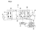
FIG. 1 is a schematic view illustrating the structure of a motor control unit according to an embodiment of the present invention. -
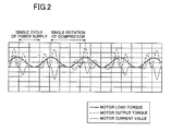
FIG. 2 is a diagram illustrating variations in load torque, output torque and current value of a motor when torque control is performed in the motor control unit according to the embodiment of the present invention. -
FIGS. 3(A) to 3(C) are diagrams illustrating variations in load torque, output torque and current value of the motor when the torque control is performed, in the motor control unit according to the embodiment of the present invention, in whichFIG. 3(A) shows the variations in response to a torque control level of 100 %,FIG. 3(B) shows the variations in response to the torque control level of 50 % andFIG. 3(C) shows the variations in response to the torque control level of 0 %. -
FIG. 4 is a schematic view illustrating the structure of a motor control unit according toModified Embodiment 1 of the present invention. -
FIGS. 5(A) to 5(C) are diagrams illustrating how to adjust a phase of a motor relative to a phase of an AC power supply when the torque control is performed in the motor control unit according toModified Embodiment 1, in whichFIG. 5(A) shows the phase of the AC power supply,FIG. 5(B) shows variations in load torque, output torque and current value of the motor before the motor phase adjustment andFIG. 5(C) shows variations in load torque, output torque and current value of the motor after the motor phase adjustment. -
FIG. 6 is a schematic view illustrating a motor control unit according to Modified Embodiment 2 of the present invention. -
FIG. 7 is a diagram illustrating a waveform of a pulse current input to an inverter. -
- 10
- Motor control unit
- 14
- Switching element
- 20
- Rectifier circuit
- 25
- Inverter circuit
- 30
- Motor
- 31
- AC power supply
- 40
- Power converter
- 41
- Motor controller
- 43
- Current detector
- Hereinafter, the present invention is described in detail by way of embodiments with reference to the drawings.
- A motor control unit (10) according to the present embodiment is connected to, for example, a brushless DC motor (30) of a single-cylinder rotary compressor connected to a refrigerant circuit of an air conditioner. As shown in
FIG. 1 , the motor control unit (10) includes a power converter (40), a motor controller (41), a current detector (43) and a load torque detector (42). The power converter (40) includes a rectifier circuit (20), a capacitor circuit (22) and an inverter circuit (25). Compressors other than the rotary compressor, e.g., multiple-cylinder compressors, may be used. Motors other than the brushless DC motor may be used. - The rectifier circuit (20) rectifies an AC voltage from an AC power supply (31). The rectifier circuit (20) is made of four diodes (12) connected in the form of a bridge. An input end of the rectifier circuit (20) is connected to the AC power supply (31). A reactor (27) is provided on a positive electrode bus between the rectifier circuit (20) and the capacitor circuit (22).
- The capacitor circuit (22) is connected between the positive electrode bus and a negative electrode bus at an output end of the rectifier circuit (20). The capacitor circuit (22) is provided with a capacitor (13) whose capacity is lower than that of a capacitor used in a conventional motor control unit. The capacity of the capacitor (13) is, for example, 1 µF to 50 µF. The capacitor circuit (22) receives an output of the rectifier circuit (20) and outputs from both ends of the capacitor (13) a rectified voltage having pulses twice as large as those of an AC voltage from the AC power supply (31).
- The inverter circuit (25) supplies a polyphase AC current (a three-phase AC current in the present embodiment) to the motor (30). In the inverter circuit (25), three circuits each including two switching elements (14) connected in series are connected in parallel between the positive and negative electrode buses. Between the two switching elements (14) of the three circuits, terminals of a three-phase coil (uvw) of the motor (30) are connected, respectively. A diode (15) is connected in parallel to each of the switching elements (14). The switching elements (14) may be, for example, power MOSFETs or IGBTs. The switching elements (14) are Si elements.
- The current detector (43) detects a current value of the motor (30). The current collector (43) is connected to at least two of three wires between the three-phase coil (uvw) and the inverter circuit (25) so that the current value detection can be carried out at all times.
- The load torque detector (42) detects a load torque of the motor (30). The load torque detector (42) is configured to detect the load torque of the motor (30) based on the current value detected by the current collector (43).
- The motor controller (41) outputs a drive signal to the switching elements (14) of the inverter circuit (25) to turn the switching elements (14) ON/OFF. The motor controller (41) controls the ON/OFF state of the switching elements (14) to adjust the rotation speed and the output torque of the motor (30). For example, when the motor (30) is running at a low speed, the motor controller (41) performs torque control to vary the output torque in response to variation in load torque of the motor (30). According to the torque control, the motor controller (41) adjusts variation in voltage command and current command of the drive signal in response to the variation in load torque of the motor (30). In this way, an ON period of the switching elements (14) in a carrier frequency is adjusted.
- The torque control by the motor controller (41) of the motor control unit (10) is explained below. In the torque control, a load torque signal representing the load torque of the motor (30) detected by the load torque detector (42) and a motor current signal representing the current value of the motor (30) detected by the current collector (43) are input to the motor controller (41).
- First, the motor controller (41) adjusts the variation in voltage command and current command of the drive signal based on the load torque signal from the load torque detector (42) so that the output torque of the motor (30) varies in response to the variation in load torque of the motor (30). The motor controller (41) outputs a drive signal in which the variation in voltage command and the current command have been adjusted to the switching elements (14) to turn the switching elements (14) ON/OFF. As a result, the output torque of the motor (30) varies in synchronization with the variation in load torque of the motor (30) as shown in
FIG. 2 . As a result of the adjustment of the variation in voltage command and current command by the motor controller (41), the ON period of the switching elements (14) in a carrier frequency is adjusted. - In the motor controller (41), a value based on a peak rated current of the switching element (14) is defined as an upper limit value of the current of the motor (30). The upper limit value is slightly lower than the peak rated current value of the switching element (14). In the torque control, the motor controller (41) adjusts a torque control level, which is the degree of variation in output torque of the motor (30), so that the current value of the motor (30) does not exceed the upper limit value.
- Specifically, in order to adjust the torque control level, the motor controller (41) adjusts the variation in voltage command and current command of a drive signal based on the motor current signal from the current collector (43) and outputs the drive signal. As the variation in voltage command and current command is adjusted, the ON period in a carrier frequency is adjusted, and then the torque control level is adjusted.
FIG. 3 shows the variation in output torque of the motor (30) and the variation in current value of the motor (30) in response to different torque control levels. When the motor controller (41) performs the torque control at a torque control level of 50%, the vibration of the compressor is reduced to half as compared with the case where the torque control is not performed. The upper limit value may be specified as a value based on the characteristics of the motor (30). - According to the present embodiment, the motor controller (41) performs the torque control to vary the output torque of the motor (30) in response to the variation in load torque that occurs in a single rotation of the motor (30). When the torque control is performed in the motor control unit (10) in which a voltage rectified by the rectifier circuit (20) is hardly smoothed and input to the inverter circuit (25), a pulse component twice as large as the frequency of the AC power supply (31) and a pulse component of the variation in load torque that occurs in the single rotation of the motor (30) are superimposed. As a result, the output torque of the motor (30) and the current of the motor (30) show waveforms including beats as shown in
FIG. 2 . A frequency analysis of the beat-including waveforms indicates that the pulse component twice as large as the frequency of the AC power supply (31) appears frequently, while the pulse component of the variation in load torque is reduced. The frequent one of the pulse components is a 100 Hz pulse component, for example when the AC power supply (31) is 50 Hz. Due to the inertia effect of the motor (30), the pulse component as high as about 100 Hz would not greatly affect the rotation speed of the motor (30). Therefore, by the torque control performed in the motor control unit (10) in which the voltage rectified by the rectifier circuit (20) is hardly smoothed and input to the inverter circuit (25), the vibration of the compressor can be reduced. - According to the present embodiment, the motor controller (41) adjust the torque control level in the torque control so that the current value of the switching element (14) of the inverter circuit (25) does not exceed the upper limit value based on the peak rated current. Since the current value of the switching element (14) of the inverter circuit (25) does not exceed the peak rated current, damage to the switching element (14) can be prevented and the motor control unit (10) can be improved in reliability.
-
Modified Embodiment 1 is explained below. According toModified Embodiment 1, as shown inFIG. 4 , the motor control unit (10) includes a power supply phase detector (45) and a motor phase detector (46). - Specifically, the power supply phase detector (45) is configured to detect the phase of the AC power supply (31). The motor phase detector (46) is configured to detect the phase of the motor (30) based on the current value of the motor (30). The motor phase detector (46) may be configured to detect the phase of the motor (30) based on the voltage value of the motor (30) or may comprise a phase detection sensor attached to the motor (30).
- In the motor control unit (10), in the torque control, a power supply phase signal representing the phase of the AC power supply (31) detected by the power supply phase detector (45) and a motor phase signal representing the phase of the motor (30) detected by the motor phase detector (46) are input to the motor controller (41). Further, the motor controller (41) stores in advance the phase of the motor (30) corresponding to the phase of the AC power supply (31) at which the peak current value of the motor (30) is minimized. For example, the motor controller (41) stores the state in which the motor (30) takes the phase shown in
FIG. 5(B) relative to the phase of the AC power supply (31) shown inFIG. 5(A) as the state in which the peak current value of the motor (30) is minimized. - The motor controller (41) comprehends the phase of the motor (30) corresponding to the present phase of the AC power supply (31) based on the power supply phase signal and the motor phase signal. Then, the motor controller (41) increases or decreases the frequency of the motor (30) to adjust the phase of the motor (30) so that it corresponds to the previously stored phase of the AC power supply (31). For example, when the motor controller (41) recognizes that the present phase of the motor (30) relative to the phase of the AC power supply (31) is in the state shown in
FIG. 5(C) , it temporarily increases the frequency of the motor (30) to adjust the phase of the motor (30) relative to the phase of the AC power supply (31) to the state shown inFIG. 5(B) . - When the motor controller (41) performs the torque control, and the rotation cycle of the motor (30) is not the integral multiple of a half cycle of the AC power supply (31), the frequency of the motor (30) is adjusted so that the rotation cycle of the motor (30) becomes the integral multiple of the half cycle of the AC power supply (31).
- According to
Modified Embodiment 1, in the torque control, the motor controller (41) adjusts the phase of the motor (30) relative to the phase of the AC power supply (31) so that the peak current value of the motor (30) is reduced. Accordingly, the current peak value of the switching element (14) of the inverter circuit (25) is reduced. This makes it possible to reduce the risk of causing damage to the switching element (14) of the inverter circuit (25), and therefore the reliability of the motor control unit (10) can be improved. As described inEmbodiment 1, when the torque control level is adjusted so that the current value of the motor (30) is less than a certain upper limit value, an upper limit value of the adjustable torque control level can be increased. As a result, the vibration of the compressor can be reduced. - Modified Embodiment 2 of the embodiment is explained below. According to Modified Embodiment 2, the motor controller (41) includes a beat rotation speed memory (47) as shown in
FIG. 6 . The beat rotation speed memory (47) stores a range of rotation speed of the motor (30) in which the motor (30) produces a beat note as a beat region. The beat region is determined by experiments performed in designing the unit and stored in the beat rotation speed memory (47). - According to the motor control unit (10), in the torque control, the motor controller (41) prohibits the motor (30) from continuously rotating at a rotation speed within a range in which the motor (30) produces the beat note. Specifically, the motor controller (41) controls the rotation speed of the motor (30) so that the motor (30) does not continuously rotate at a rotation speed within the range in which the motor (30) produces the beat note. For example, when the rotation speed of the motor (30) is adjusted from a value smaller than the beat-producing range to a value larger than the beat-producing range, the rotation speed of the motor (30) temporarily passes through the beat-producing range. However, due to the operation of the motor controller (41), the rotation speed of the motor (30) is prevented from remaining in the beat-producing range.
- According to Modified Embodiment 2, the motor (30) is less likely to produce the beat note. This makes it possible to improve quietness of the compressor whose vibration is reduced by the torque control.
- The above-described embodiment may be varied in the following manner.
- The switching element (14) of the embodiment may be, for example, a wide-band-gap semiconductor element such as a SiC element, a GaN element and a diamond element. As compared with a Si element, the wide-band-gap semiconductor element has a larger bandgap and higher heat resistance, and therefore is able to increase the peak rated current to a greater extent given that their current capacities are the same. The wide-band-gap semiconductor element preferably has a bandgap of not less than 1.2 eV, more preferably not less than 2.0 eV.
- The description of the preferred embodiment is provided only for explanation purpose and does not limit the present invention, an object to which the present invention is applied and use of the invention.
- As described above, the present invention is useful for motor control units for controlling motors of compressors including a rectifier circuit and an inverter circuit.
Claims (6)
- A motor control unit for controlling a motor (30) of a compressor in which a load torque varies in a single rotation in the course of fluid compression by the compressor, the motor control unit comprising:a power converter (40) having a rectifier circuit (20) which rectifies an AC voltage from an AC power supply (31), a capacitor circuit (22) which receives an output of the rectifier circuit (20) and outputs a rectified voltage having pulses from both ends of a capacitor (13) and an inverter circuit (25) which receives the rectified voltage and outputs an AC voltage to the motor (30); anda motor controller (41) controlling the motor (30) by controlling the inverter circuit (25), whereinthe motor controller (41) performs torque control to vary an output toque of the motor (30) in response to variation in load torque of the motor (30).
- The motor control unit of claim 1, further comprising:a current detector (43) detecting a current value of the motor (30), whereinthe motor controller (41) adjusts a torque control level in the torque control so that a current value of the motor (30) detected by the current collector (43) does not exceed an upper limit value based on a peak rated current of a switching element (14) of the inverter circuit (25) or an upper limit value based on characteristics of the motor (30).
- The motor control unit of claim 1, wherein
in the torque control, the motor controller (41) adjusts a phase of the motor (30) relative to a phase of the AC power supply (31) so that a peak current value of the motor (30) is reduced. - The motor control unit of claim 1, wherein
in the torque control, the motor controller (41) prohibits the motor (30) from continuously rotating at a rotation speed within a range in which the motor (30) produces a beat note. - The motor control unit of any one of claims 1 to 4, wherein
the switching element (14) of the inverter circuit (25) is a wide-band-gap semiconductor element. - The motor control unit of claim 5, wherein
the switching element (14) of the inverter circuit (25) is a SiC element.
Applications Claiming Priority (2)
| Application Number | Priority Date | Filing Date | Title |
|---|---|---|---|
| JP2006236354A JP4192979B2 (en) | 2006-08-31 | 2006-08-31 | Motor control device |
| PCT/JP2007/066778 WO2008026643A1 (en) | 2006-08-31 | 2007-08-29 | Motor control device |
Publications (2)
| Publication Number | Publication Date |
|---|---|
| EP2058937A1 true EP2058937A1 (en) | 2009-05-13 |
| EP2058937A4 EP2058937A4 (en) | 2017-07-26 |
Family
ID=39135925
Family Applications (1)
| Application Number | Title | Priority Date | Filing Date |
|---|---|---|---|
| EP07806255.1A Ceased EP2058937A4 (en) | 2006-08-31 | 2007-08-29 | Motor control device |
Country Status (7)
| Country | Link |
|---|---|
| US (1) | US8098035B2 (en) |
| EP (1) | EP2058937A4 (en) |
| JP (1) | JP4192979B2 (en) |
| KR (1) | KR101077718B1 (en) |
| CN (1) | CN101507097B (en) |
| AU (1) | AU2007289666B2 (en) |
| WO (1) | WO2008026643A1 (en) |
Cited By (4)
| Publication number | Priority date | Publication date | Assignee | Title |
|---|---|---|---|---|
| EP2620722A3 (en) * | 2012-01-30 | 2014-01-08 | LG Electronics, Inc. | Apparatus for controlling compressor and refrigerator having the same |
| EP2667501A4 (en) * | 2011-01-18 | 2017-07-26 | Daikin Industries, Ltd. | Power conversion apparatus |
| EP2760125A3 (en) * | 2013-01-23 | 2018-01-10 | Lg Electronics Inc. | Motor control apparatus and method |
| EP2482438A3 (en) * | 2011-01-26 | 2018-03-28 | Mitsubishi Electric Corporation | Power converter |
Families Citing this family (34)
| Publication number | Priority date | Publication date | Assignee | Title |
|---|---|---|---|---|
| JP2011072142A (en) * | 2009-09-28 | 2011-04-07 | Daikin Industries Ltd | Power converter |
| GB201006390D0 (en) | 2010-04-16 | 2010-06-02 | Dyson Technology Ltd | Control of a brushless motor |
| GB201006398D0 (en) | 2010-04-16 | 2010-06-02 | Dyson Technology Ltd | Control of a brushless motor |
| GB201006396D0 (en) | 2010-04-16 | 2010-06-02 | Dyson Technology Ltd | Control of a brushless motor |
| GB201006388D0 (en) | 2010-04-16 | 2010-06-02 | Dyson Technology Ltd | Control of brushless motor |
| GB201006391D0 (en) | 2010-04-16 | 2010-06-02 | Dyson Technology Ltd | Control of a brushless permanent-magnet motor |
| GB201006397D0 (en) | 2010-04-16 | 2010-06-02 | Dyson Technology Ltd | Control of a brushless motor |
| GB201006384D0 (en) * | 2010-04-16 | 2010-06-02 | Dyson Technology Ltd | Control of a brushless motor |
| GB201006387D0 (en) * | 2010-04-16 | 2010-06-02 | Dyson Technology Ltd | Control of a brushless motor |
| GB201006386D0 (en) | 2010-04-16 | 2010-06-02 | Dyson Technology Ltd | Control of a brushless motor |
| GB201006392D0 (en) | 2010-04-16 | 2010-06-02 | Dyson Technology Ltd | Controller for a brushless motor |
| GB201006395D0 (en) | 2010-04-16 | 2010-06-02 | Dyson Technology Ltd | Control of a brushless motor |
| JP5321530B2 (en) * | 2010-04-23 | 2013-10-23 | 三菱電機株式会社 | Three-phase voltage type PWM inverter control device |
| EP2613106B1 (en) * | 2010-08-30 | 2015-09-23 | Mitsubishi Electric Corporation | Heat pump device, heat pump system and three-phase inverter control method |
| GB2484289B (en) | 2010-10-04 | 2013-11-20 | Dyson Technology Ltd | Control of an electrical machine |
| JP5673118B2 (en) * | 2011-01-18 | 2015-02-18 | ダイキン工業株式会社 | Power converter |
| CN103038993B (en) * | 2011-05-26 | 2016-04-20 | 松下电器产业株式会社 | AC transform circuit, AC conversion method and recording medium |
| KR101214489B1 (en) * | 2011-06-13 | 2012-12-24 | 엘지전자 주식회사 | Apparatus for controlling compressor and method of the same |
| JP5899824B2 (en) * | 2011-11-07 | 2016-04-06 | ダイキン工業株式会社 | Preheating device |
| EP2784924B1 (en) * | 2011-11-22 | 2018-11-07 | Panasonic Corporation | Ac conversion circuit |
| CN102522941B (en) * | 2011-12-21 | 2017-03-22 | 海尔集团公司 | Method for suppressing low-frequency vibration of compressor and system for suppressing low-frequency vibration of compressor |
| JP5319798B2 (en) * | 2012-01-25 | 2013-10-16 | ファナック株式会社 | Motor control device that limits torque command according to input current or power |
| JP6137090B2 (en) * | 2014-09-02 | 2017-05-31 | 株式会社デンソー | Motor control device |
| KR102253892B1 (en) * | 2014-10-31 | 2021-05-20 | 엘지전자 주식회사 | Apparatus and method for controlling a compressor |
| NO338836B1 (en) * | 2015-06-11 | 2016-10-24 | Fmc Kongsberg Subsea As | Load-sharing in parallel fluid pumps |
| US11018615B2 (en) * | 2017-08-04 | 2021-05-25 | Mitsubishi Electric Corporation | Motor drive device and air conditioner |
| CN111149287B (en) * | 2017-09-29 | 2020-11-13 | 大金工业株式会社 | power conversion device |
| JP6521131B1 (en) | 2018-03-29 | 2019-05-29 | ダイキン工業株式会社 | Power converter |
| JP6991336B2 (en) * | 2018-07-26 | 2022-01-12 | 三菱電機株式会社 | Motor drive device and refrigeration cycle applicable equipment |
| JP6849000B2 (en) | 2019-03-14 | 2021-03-24 | ダイキン工業株式会社 | Direct power converter |
| MY210400A (en) * | 2020-02-03 | 2025-09-19 | Panasonic Ip Man Co Ltd | Electric motor drive device |
| EP3984705A1 (en) * | 2020-09-16 | 2022-04-20 | Black & Decker Inc. | Power adaptor, power tool and power tool system |
| DE102023101433A1 (en) * | 2023-01-20 | 2024-07-25 | Festool Gmbh | Power tool, arrangement, method, computer program product and computer-readable medium |
| TWI872746B (en) * | 2023-10-20 | 2025-02-11 | 茂達電子股份有限公司 | Motor driver for adjusting power based on common voltage |
Family Cites Families (14)
| Publication number | Priority date | Publication date | Assignee | Title |
|---|---|---|---|---|
| JPH0742939B2 (en) * | 1985-10-07 | 1995-05-15 | 株式会社日立製作所 | Torque controlled compressor |
| JPH0642789B2 (en) | 1989-05-25 | 1994-06-01 | 株式会社東芝 | Control device for compressor electric motor |
| FR2757709B1 (en) * | 1996-12-19 | 1999-03-05 | Sgs Thomson Microelectronics | INDUCTION MOTOR REGULATOR |
| JP3691269B2 (en) | 1999-01-12 | 2005-09-07 | シャープ株式会社 | Motor control device |
| JP3544338B2 (en) | 2000-03-23 | 2004-07-21 | シャープ株式会社 | Control device for compressor motor |
| JP2002051589A (en) | 2000-07-31 | 2002-02-15 | Isao Takahashi | Controller for inverter for drive of motor |
| JP3699663B2 (en) * | 2001-05-24 | 2005-09-28 | 勲 高橋 | Inverter control method and apparatus |
| JP3766348B2 (en) | 2002-05-20 | 2006-04-12 | 三菱電機株式会社 | Electric motor torque control apparatus, electric motor torque control method, hermetic compressor, and refrigeration cycle apparatus |
| JP3971316B2 (en) * | 2003-01-31 | 2007-09-05 | 関西電力株式会社 | Instantaneous large power supply device |
| EP1617551A4 (en) * | 2003-04-22 | 2010-09-08 | Panasonic Corp | ENGINE CONTROL DEVICE, COMPRESSOR, AIR CONDITIONER AND REFRIGERATOR |
| JP4575704B2 (en) * | 2003-04-22 | 2010-11-04 | パナソニック株式会社 | Motor control device, compressor, air conditioner, and refrigerator |
| JP4679848B2 (en) * | 2003-07-18 | 2011-05-11 | パナソニック株式会社 | Motor drive device |
| EP1501186B1 (en) * | 2003-07-18 | 2018-08-22 | III Holdings 10, LLC | Motor driving apparatus |
| JP2005204404A (en) | 2004-01-15 | 2005-07-28 | Matsushita Electric Ind Co Ltd | Motor drive device |
-
2006
- 2006-08-31 JP JP2006236354A patent/JP4192979B2/en not_active Expired - Fee Related
-
2007
- 2007-08-29 KR KR1020097004874A patent/KR101077718B1/en active Active
- 2007-08-29 CN CN2007800306462A patent/CN101507097B/en active Active
- 2007-08-29 AU AU2007289666A patent/AU2007289666B2/en active Active
- 2007-08-29 WO PCT/JP2007/066778 patent/WO2008026643A1/en not_active Ceased
- 2007-08-29 US US12/439,496 patent/US8098035B2/en active Active
- 2007-08-29 EP EP07806255.1A patent/EP2058937A4/en not_active Ceased
Non-Patent Citations (1)
| Title |
|---|
| See references of WO2008026643A1 * |
Cited By (5)
| Publication number | Priority date | Publication date | Assignee | Title |
|---|---|---|---|---|
| EP2667501A4 (en) * | 2011-01-18 | 2017-07-26 | Daikin Industries, Ltd. | Power conversion apparatus |
| EP2482438A3 (en) * | 2011-01-26 | 2018-03-28 | Mitsubishi Electric Corporation | Power converter |
| EP2620722A3 (en) * | 2012-01-30 | 2014-01-08 | LG Electronics, Inc. | Apparatus for controlling compressor and refrigerator having the same |
| US9163621B2 (en) | 2012-01-30 | 2015-10-20 | Lg Electronics Inc. | Apparatus for controlling compressor and refrigerator having the same |
| EP2760125A3 (en) * | 2013-01-23 | 2018-01-10 | Lg Electronics Inc. | Motor control apparatus and method |
Also Published As
| Publication number | Publication date |
|---|---|
| AU2007289666B2 (en) | 2011-09-01 |
| KR20090039832A (en) | 2009-04-22 |
| US8098035B2 (en) | 2012-01-17 |
| CN101507097B (en) | 2012-11-07 |
| AU2007289666A1 (en) | 2008-03-06 |
| JP2008061409A (en) | 2008-03-13 |
| CN101507097A (en) | 2009-08-12 |
| EP2058937A4 (en) | 2017-07-26 |
| KR101077718B1 (en) | 2011-10-27 |
| US20090251086A1 (en) | 2009-10-08 |
| JP4192979B2 (en) | 2008-12-10 |
| WO2008026643A1 (en) | 2008-03-06 |
Similar Documents
| Publication | Publication Date | Title |
|---|---|---|
| US8098035B2 (en) | Motor control unit | |
| JP5274579B2 (en) | AC / DC converter, motor drive | |
| CN102106070B (en) | AC-DC converter, air conditioner, and heat pump-type hot-water supply device | |
| US9960703B2 (en) | DC power-supply device and refrigeration-cycle application device including the same | |
| CN101326707B (en) | Inverter device | |
| CN101981800B (en) | Power conversion device | |
| US9692332B2 (en) | Power conversion device | |
| AU2006335684B2 (en) | Electric motor driving device and compressor driving device | |
| US11632071B2 (en) | Motor drive device and air conditioner | |
| EP3182574A1 (en) | Converter unit, drive controller, motor, and compressor | |
| CN105191105A (en) | DC power supply device and refrigeration cycle employing device equipped with same | |
| CN102097958B (en) | Power supply circuit, motor drive device using the same and refrigeration device | |
| CN116420302B (en) | Power conversion device, motor drive device, and refrigeration cycle application device | |
| CN110870198A (en) | Drive device, control method and program | |
| CN110870184A (en) | Power supply device, drive device, control method, and program | |
| JP2004072806A (en) | Power converter | |
| JP2009278789A (en) | Inverter controller for motor drive | |
| US20240396486A1 (en) | Power conversion apparatus, motor drive apparatus, and refrigeration cycle application apparatus | |
| JP2012165582A (en) | Motor controller | |
| CN109546866B (en) | Air conditioning system, variable frequency controller and alternating current estimation method and device thereof | |
| JP2008061421A (en) | Motor control device | |
| WO2023105689A1 (en) | Power conversion device, electric motor drive device, and refrigeration cycle application device | |
| JP3961868B2 (en) | Power converter | |
| JP2009254124A (en) | Brushless dc motor controller | |
| JP2004215434A (en) | Motor control device, air conditioner and refrigerator using the control device |
Legal Events
| Date | Code | Title | Description |
|---|---|---|---|
| PUAI | Public reference made under article 153(3) epc to a published international application that has entered the european phase |
Free format text: ORIGINAL CODE: 0009012 |
|
| 17P | Request for examination filed |
Effective date: 20090218 |
|
| AK | Designated contracting states |
Kind code of ref document: A1 Designated state(s): AT BE BG CH CY CZ DE DK EE ES FI FR GB GR HU IE IS IT LI LT LU LV MC MT NL PL PT RO SE SI SK TR |
|
| AX | Request for extension of the european patent |
Extension state: AL BA HR MK RS |
|
| RIN1 | Information on inventor provided before grant (corrected) |
Inventor name: SEKIMOTO, MORIMITSU Inventor name: MAEDA, TOSHIYUKI Inventor name: MECHI, ABDALLAH Inventor name: KAWASHIMA, REIJI Inventor name: SAKAKIBARA, KENICHI Inventor name: HAGA, HITOSHI |
|
| DAX | Request for extension of the european patent (deleted) | ||
| RA4 | Supplementary search report drawn up and despatched (corrected) |
Effective date: 20170623 |
|
| RIC1 | Information provided on ipc code assigned before grant |
Ipc: H02P 29/032 20160101ALI20170619BHEP Ipc: H02P 29/50 20160101ALI20170619BHEP Ipc: H02P 6/10 20060101AFI20170619BHEP Ipc: H02P 23/30 20160101ALI20170619BHEP |
|
| STAA | Information on the status of an ep patent application or granted ep patent |
Free format text: STATUS: EXAMINATION IS IN PROGRESS |
|
| 17Q | First examination report despatched |
Effective date: 20190628 |
|
| REG | Reference to a national code |
Ref country code: DE Ref legal event code: R003 |
|
| STAA | Information on the status of an ep patent application or granted ep patent |
Free format text: STATUS: THE APPLICATION HAS BEEN REFUSED |
|
| 18R | Application refused |
Effective date: 20220505 |