EP2058895A1 - Battery module - Google Patents
Battery module Download PDFInfo
- Publication number
- EP2058895A1 EP2058895A1 EP20080168712 EP08168712A EP2058895A1 EP 2058895 A1 EP2058895 A1 EP 2058895A1 EP 20080168712 EP20080168712 EP 20080168712 EP 08168712 A EP08168712 A EP 08168712A EP 2058895 A1 EP2058895 A1 EP 2058895A1
- Authority
- EP
- European Patent Office
- Prior art keywords
- batteries
- openings
- battery
- unit
- duct member
- Prior art date
- Legal status (The legal status is an assumption and is not a legal conclusion. Google has not performed a legal analysis and makes no representation as to the accuracy of the status listed.)
- Granted
Links
Images





Classifications
-
- H—ELECTRICITY
- H01—ELECTRIC ELEMENTS
- H01M—PROCESSES OR MEANS, e.g. BATTERIES, FOR THE DIRECT CONVERSION OF CHEMICAL ENERGY INTO ELECTRICAL ENERGY
- H01M10/00—Secondary cells; Manufacture thereof
- H01M10/60—Heating or cooling; Temperature control
- H01M10/61—Types of temperature control
- H01M10/613—Cooling or keeping cold
-
- H—ELECTRICITY
- H01—ELECTRIC ELEMENTS
- H01M—PROCESSES OR MEANS, e.g. BATTERIES, FOR THE DIRECT CONVERSION OF CHEMICAL ENERGY INTO ELECTRICAL ENERGY
- H01M10/00—Secondary cells; Manufacture thereof
- H01M10/60—Heating or cooling; Temperature control
- H01M10/62—Heating or cooling; Temperature control specially adapted for specific applications
- H01M10/625—Vehicles
-
- H—ELECTRICITY
- H01—ELECTRIC ELEMENTS
- H01M—PROCESSES OR MEANS, e.g. BATTERIES, FOR THE DIRECT CONVERSION OF CHEMICAL ENERGY INTO ELECTRICAL ENERGY
- H01M10/00—Secondary cells; Manufacture thereof
- H01M10/60—Heating or cooling; Temperature control
- H01M10/64—Heating or cooling; Temperature control characterised by the shape of the cells
- H01M10/643—Cylindrical cells
-
- H—ELECTRICITY
- H01—ELECTRIC ELEMENTS
- H01M—PROCESSES OR MEANS, e.g. BATTERIES, FOR THE DIRECT CONVERSION OF CHEMICAL ENERGY INTO ELECTRICAL ENERGY
- H01M10/00—Secondary cells; Manufacture thereof
- H01M10/60—Heating or cooling; Temperature control
- H01M10/65—Means for temperature control structurally associated with the cells
- H01M10/655—Solid structures for heat exchange or heat conduction
- H01M10/6556—Solid parts with flow channel passages or pipes for heat exchange
- H01M10/6557—Solid parts with flow channel passages or pipes for heat exchange arranged between the cells
-
- H—ELECTRICITY
- H01—ELECTRIC ELEMENTS
- H01M—PROCESSES OR MEANS, e.g. BATTERIES, FOR THE DIRECT CONVERSION OF CHEMICAL ENERGY INTO ELECTRICAL ENERGY
- H01M10/00—Secondary cells; Manufacture thereof
- H01M10/60—Heating or cooling; Temperature control
- H01M10/65—Means for temperature control structurally associated with the cells
- H01M10/656—Means for temperature control structurally associated with the cells characterised by the type of heat-exchange fluid
- H01M10/6561—Gases
- H01M10/6563—Gases with forced flow, e.g. by blowers
-
- H—ELECTRICITY
- H01—ELECTRIC ELEMENTS
- H01M—PROCESSES OR MEANS, e.g. BATTERIES, FOR THE DIRECT CONVERSION OF CHEMICAL ENERGY INTO ELECTRICAL ENERGY
- H01M10/00—Secondary cells; Manufacture thereof
- H01M10/60—Heating or cooling; Temperature control
- H01M10/65—Means for temperature control structurally associated with the cells
- H01M10/656—Means for temperature control structurally associated with the cells characterised by the type of heat-exchange fluid
- H01M10/6561—Gases
- H01M10/6566—Means within the gas flow to guide the flow around one or more cells, e.g. manifolds, baffles or other barriers
-
- H—ELECTRICITY
- H01—ELECTRIC ELEMENTS
- H01M—PROCESSES OR MEANS, e.g. BATTERIES, FOR THE DIRECT CONVERSION OF CHEMICAL ENERGY INTO ELECTRICAL ENERGY
- H01M50/00—Constructional details or processes of manufacture of the non-active parts of electrochemical cells other than fuel cells, e.g. hybrid cells
- H01M50/20—Mountings; Secondary casings or frames; Racks, modules or packs; Suspension devices; Shock absorbers; Transport or carrying devices; Holders
- H01M50/204—Racks, modules or packs for multiple batteries or multiple cells
- H01M50/207—Racks, modules or packs for multiple batteries or multiple cells characterised by their shape
- H01M50/213—Racks, modules or packs for multiple batteries or multiple cells characterised by their shape adapted for cells having curved cross-section, e.g. round or elliptic
-
- H—ELECTRICITY
- H01—ELECTRIC ELEMENTS
- H01M—PROCESSES OR MEANS, e.g. BATTERIES, FOR THE DIRECT CONVERSION OF CHEMICAL ENERGY INTO ELECTRICAL ENERGY
- H01M50/00—Constructional details or processes of manufacture of the non-active parts of electrochemical cells other than fuel cells, e.g. hybrid cells
- H01M50/20—Mountings; Secondary casings or frames; Racks, modules or packs; Suspension devices; Shock absorbers; Transport or carrying devices; Holders
- H01M50/289—Mountings; Secondary casings or frames; Racks, modules or packs; Suspension devices; Shock absorbers; Transport or carrying devices; Holders characterised by spacing elements or positioning means within frames, racks or packs
- H01M50/291—Mountings; Secondary casings or frames; Racks, modules or packs; Suspension devices; Shock absorbers; Transport or carrying devices; Holders characterised by spacing elements or positioning means within frames, racks or packs characterised by their shape
-
- Y—GENERAL TAGGING OF NEW TECHNOLOGICAL DEVELOPMENTS; GENERAL TAGGING OF CROSS-SECTIONAL TECHNOLOGIES SPANNING OVER SEVERAL SECTIONS OF THE IPC; TECHNICAL SUBJECTS COVERED BY FORMER USPC CROSS-REFERENCE ART COLLECTIONS [XRACs] AND DIGESTS
- Y02—TECHNOLOGIES OR APPLICATIONS FOR MITIGATION OR ADAPTATION AGAINST CLIMATE CHANGE
- Y02E—REDUCTION OF GREENHOUSE GAS [GHG] EMISSIONS, RELATED TO ENERGY GENERATION, TRANSMISSION OR DISTRIBUTION
- Y02E60/00—Enabling technologies; Technologies with a potential or indirect contribution to GHG emissions mitigation
- Y02E60/10—Energy storage using batteries
Definitions
- the present invention relates to a battery module including a plurality of batteries. More particularly, the present invention relates to a battery module having a coolant passage for cooling batteries and a gas exhaust passage for exhausting gas generated from the batteries.
- a rechargeable battery may be repeatedly charged and discharged.
- a low capacity rechargeable battery composed of a single cell is generally used for a portable small electronic device, such as a mobile phone, a laptop computer, and a camcorder.
- a large capacity rechargeable battery composed of a plurality of cells connected in a form of a pack is widely used to drive a motor for a hybrid electric vehicle.
- Such rechargeable batteries are serially connected to form a rechargeable battery module to drive a motor for an electric vehicle, which needs a large amount of electric power.
- a battery module is composed of a plurality of serially connected rechargeable batteries.
- rechargeable battery refers to a (unit) battery throughout the specification for better understanding and ease of description.
- Each unit battery includes an electrode assembly having an anode and a cathode with a separator interposed therebetween, a case having a space for housing the electrode assembly, and a cap assembly coupled to the case for closing and sealing the case and having an electrode terminal electrically connected to the electrode assembly.
- unit batteries are arranged at regular intervals in a housing and terminals of the unit batteries are connected with each other, thereby forming a battery module.
- the battery module Since many unit batteries are connected to form one battery module, the battery module must effectively dissipate heat generated from each unit battery.
- the heat dissipation characteristic of the battery module is very important because the performance of not only the unit batteries but also an electronic device employing the battery module is significantly influenced by the heat dissipation characteristic.
- the battery module may not output sufficient power to drive an electric cleaner, an electric scooter, or a vehicle (e.g., an electric vehicle or a hybrid electric vehicle). If the internal temperature increases by the heat generated from the unit batteries, an abnormal reaction occurs internally. As a result, the charging and discharging performance of the unit batteries is deteriorated.
- gas may be generated in the unit battery while charging and discharging are repeatedly performed.
- the battery module includes the plurality of unit batteries connected to each other, the gas is required to be quickly and efficiently released. That is, when the gas is not efficiently released, internal pressure increases in the unit battery, and there may be a danger of a rupture or explosion.
- a battery module including a coolant passage for exhausting heat from a unit battery and a gas exhaust passage for exhausting gas.
- the battery module includes a coolant passage for exhausting heat from a unit battery and a gas exhaust passage while a size of the battery module is not problematically increased.
- a battery module comprising:
- a battery module includes a plurality of unit batteries (or simply batteries), a housing, and a duct member.
- the plurality of unit batteries are electrically connected to each other
- the housing has a plurality of openings (or penetration holes) in which the unit batteries are provided to respectively correspond to the unit batteries
- the duct member is combined with the housing to cover electrode terminals of the unit batteries.
- the duct member includes a coolant passage through which a coolant is provided to the openings and a gas exhaust passage for exhausting gas generated from the unit batteries in a predetermined direction.
- the battery module further may include a separating unit formed in the duct member to separate the coolant passage and the gas exhaust passage.
- the separating unit may protrude toward the electrode terminal of the unit battery such that the coolant passage is penetrated through in a direction toward the electrode terminal.
- the coolant passage may communicate with a space between the unit battery and the opening.
- the separating unit may be formed in plural to respectively correspond to the unit batteries, and the plurality of separating units are formed in a plurality of rows to form the gas exhaust passage between the rows.
- the duct member may include an outlet communicating with the gas exhaust passage, and the gas generated from the unit batteries is exhausted through the gas exhaust passage and the outlet.
- the separating unit may include an opening formed in a shape that partially surrounds a circumference of the electrode terminal of the unit battery.
- the openings of a pair of neighboring separating units among the plurality of separating units may face each other.
- the unit batteries corresponding to the pair of separating units are electrically connected by a terminal plate, and the terminal plate is positioned at a space formed by the openings of the pair of separating units.
- Sizes of the plurality of separating units may be differently formed according to locations of the separating units in the duct member.
- the battery module may further include a covering member having an internal space for supplying the coolant to the coolant passage while covering the duct member.
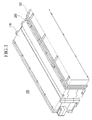
- FIG. 1 is a perspective view of a battery module according to an exemplary embodiment of the present invention.
- a battery module 100 includes a coolant passage for cooling a temperature of a unit battery to be lower than a predetermined temperature, and a gas exhaust passage for externally exhausting gas generated in the unit battery. That is, the battery module 100 includes following constituent elements.
- the battery module 100 includes a housing 110 including a plurality of unit batteries, a covering member 120 combined with the housing 110 to cover the unit batteries, and a duct member 200 integrally combined between the housing 110 and the covering member 120 to cover electrode terminals of the unit batteries.
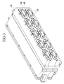
- FIG. 2 is a perspective view of a battery module in which the covering member shown in FIG. 1 is removed.
- the duct member 200 includes a coolant passage 210. Since a coolant provided through the coolant passage 210 is supplied to a unit battery in the housing 110, heat generated in the unit battery may be reduced. In this case, air in the atmosphere or cooling air that is cooled to a predetermined temperature may be used as the coolant.
- the coolant may be externally supplied to the coolant passage 210, or it may be supplied to the coolant passage 210 through the covering member 120. That is, the covering member 120 includes an inner space of a predetermined size to externally receive the coolant. In addition, the covering member 120 dispersedly supplies the coolant to the coolant passage 210.
- FIG. 3 is a perspective view of the battery module in which the duct member 200 shown in FIG. 2 is removed.
- the battery module 100 includes a plurality of unit batteries 130 electrically connected to each other, and the unit batteries 130 are provided in the housing 110.
- the housing 110 includes a plurality of openings, and the plurality of unit batteries 130 are respectively provided in the corresponding openings.
- the plurality of unit batteries 130 are exemplarily shown to be accumulated in two layers in the battery module 100, but they may be accumulated in multiple layers according to power capacity of the battery module 100.
- Pairs of neighboring unit batteries 130 among the plurality of unit batteries 130 are electrically connected by a terminal plate 140, and the terminal plate 140 is combined with an electrode terminal of the unit battery 130 by a fastening member 150.
- a combining relationship and a location relationship among the housing 110, the unit battery 130, and the duct member 200 will now be described.
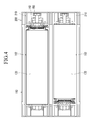
- FIG. 4 is a cross-sectional view representing a combining relationship between the housing including the unit battery and the duct member along a line IV-IV shown in FIG. 2 .
- the housing 110 includes a plurality of openings 112 included with the unit batteries 130.
- each unit battery 130 is formed in a cylindrical shape, but it is not limited thereto, and it may be formed in a square shape or various other shapes.
- the opening 112 is formed in a cylindrical shape corresponding to the unit battery 130.
- the opening 112 is formed to be bigger than a cross-section of the cylindrical shape of the unit battery 130, and therefore a space for continuously flowing the coolant is maintained between the unit battery 130 and the opening 112.
- the coolant passage 210 since the coolant passage 210 communicates with the space between the unit battery 130 and the opening 112 when the housing 110 and the duct member 200 are combined, the coolant provided through the coolant passage 210 may remove heat generated from a surface of the unit battery 130.
- the plurality of unit batteries 130 is coupled in series in the battery module 100.
- the unit batteries 130 in the housing 110 are alternately arranged such that anodes or cathodes of the neighboring unit batteries are not arranged in the same direction but are arranged in opposite directions.
- An anode terminal and a cathode terminal of the neighboring unit batteries 130 are electrically connected by the terminal plate 140.
- the duct member 200 according to the exemplary embodiment of the present invention is formed as shown in FIG. 5 and FIG. 6 to exhaust the gas generated from the unit battery to the outside of the battery module 100.
- FIG. 5 is a perspective view of the duct member shown in FIG. 2
- FIG. 6 is a top plan view of the duct member shown in FIG. 5 .
- the duct member 200 includes separating units 220 and 221 for separating coolant passages 210 and 211 and the gas exhaust passage.
- the separating units 220 and 221 are protruded toward the electrode terminal of the unit battery 130 such that the coolant passages 210 and 211 are penetrated through.
- the separating units 220 and 221 correspond to each unit battery 130, and the plurality of separating units 220 and 221 are arranged in two rows.
- the gas exhaust passage (an area where arrows shown in FIG. 5 and FIG. 6 are arranged in a row) is formed between the rows.
- the separating units 220 and 221 respectively have an opening partially surrounding a circumference of the electrode terminal of the unit battery 130, and are formed in a C shape.
- the coolant passages 210 and 211 directly communicate with the space between the unit battery 130 and the opening 112.
- the gas exhausted from an electrode terminal direction of the unit battery 130 is provided to the gas exhaust passage through the openings of the separating units 220 and 221, and is exhausted from the duct member 200 through the gas exhaust passage.
- the separating units 220 and 221 separately form the coolant passages 210 and 211 and the gas exhaust passage, and interrupt the coolant supplied through the coolant passages 210 and 211 from the gas exhausted from the unit battery 130.
- a pair of neighboring separating units 220 and 221 among the plurality of separating units is formed so that the openings face each other. That is, the terminal plate 140 electrically connecting the pair of unit batteries 130 is positioned at a space formed by the openings of the pair of separating units 220 and 221.
- the duct member 200 includes an outlet 240 communicating with the gas exhaust passage, and the gas generated from the unit batteries 130 is exhausted through the outlet 240.
- the duct member 200 may further include a blowing unit for forcibly inducing gas flow so that the gas generated from the unit batteries 130 flows in one direction along the gas exhaust passage.
- Heat is differently generated according to an arrangement of the plurality of unit batteries 130 in the battery module 100, and thermal imbalance may occur between the plurality of unit batteries 130 when the same amount of coolant is supplied. Accordingly, sizes and openings of the plurality of separating units 220 and 221 are differently formed in the battery module 100. That is, since a flowing amount of the coolant may vary according to the openings or the size of the separating units 220 and 221 in the coolant passages 210 and 211, shapes of the plurality of separating units 220 and 221 respectively corresponding to the unit batteries 130 may be varied.
- heat of the unit battery 130 located on a center part of the housing 110 may not be efficiently exhausted compared to other unit batteries 130 due to its location.
- the battery module 100 according to the exemplary embodiment of the present invention since the openings and the size of the separating units 220 and 221 corresponding to the unit battery 130 at a predetermined area are formed to be relatively smaller than other unit batteries 130, cooling performance of the unit battery 130 at the predetermined area may be increased.
- FIG. 7A to FIG. 7C show diagrams representing the duct members that may be applied to the battery module according to the exemplary embodiment of the present invention.
- the plurality of separating units are respectively formed to have openings as large as central angle of 76° of circular sections in a first exemplary embodiment ( FIG. 7A ), and five separating units positioned on an upper row among the plurality of separating units are respectively formed to have openings as large as central angle of 180° of circular sections and remaining separating units are respectively formed to have openings as large as central angle of 76° of circular sections in a second exemplary embodiment ( FIG. 7B ).
- FIG. 7C five respective separating units positioned on upper and lower rows among the plurality of separating units are respectively formed to have openings as large as central angle of 180° of circular sections, and remaining separating units are formed to have openings as large as central angle of 76° of circular sections.
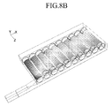
- heat generation temperatures in the respective unit batteries in the battery modules are shown as FIG. 8A to FIG. 8C , and measured values of the temperatures are given as in FIG. 9 .
- the temperatures are surface temperatures of the respective unit batteries, and an average temperature, a temperature measured at a 1/3 point in a length direction of the unit cell, and a temperature measured at a 2/3 point in the length direction of the unit cell are shown.
- temperature deviation of the unit batteries is less than in the first and second exemplary embodiments ( FIG. 7A) and (FIG. 7B ).
- FIG. 10 is a graph representing temperatures of the respective cells for varied shape and size of the separating units while the voltage of the cooling fan is varied.
- heat generation varies according to voltages 8V, 10V, 12V, and 14V of a cooling fan, but heat generation temperatures of cells 12 to 21 are lower than the heat generation temperatures of cells 1 to 10. That is, the separating units are formed to have openings as large as central angle of 76° of the circular sections in the cells 1 to 10, and the separating units are formed to have openings as large as central angle of 180° of the circular sections in the cells 12 to 21.
- the temperatures of the unit batteries may be controlled.
- the gas generated from the unit battery may be efficiently exhausted while the unit battery is cooled down. Accordingly, the battery module may be more stably driven and may efficiently output required power.
- the battery module according to the exemplary embodiment of the present invention separately includes a coolant passage for heat dissipation of the unit battery and a gas exhaust passage for exhausting gas, the size of the battery module may not be problematically increased.
Landscapes
- Chemical & Material Sciences (AREA)
- Chemical Kinetics & Catalysis (AREA)
- Electrochemistry (AREA)
- General Chemical & Material Sciences (AREA)
- Engineering & Computer Science (AREA)
- Manufacturing & Machinery (AREA)
- Secondary Cells (AREA)
- Battery Mounting, Suspending (AREA)
- Gas Exhaust Devices For Batteries (AREA)
Abstract
a plurality of batteries (130) wherein at least some of the batteries (130) are electrically coupled to each other;
a housing (110) that defines a plurality of openings (112) that are sized so as to receive the plurality of batteries (130), wherein the plurality of openings (112) are further sized so as to provide a space about the outer surface of the plurality of batteries (130) positioned therein so as to permit fluid to flow over the outer surface of the batteries (130) to facilitate heat dissipation;
a duct member (200) that is positioned on the housing (100) wherein the duct member (200) defines a flow path that allows coolant to be circulated into the plurality of openings (112) to facilitate heat dissipation about the batteries (130) and a gas exhaust passage that permits removal of heat from the housing (110).
Description
- The present invention relates to a battery module including a plurality of batteries. More particularly, the present invention relates to a battery module having a coolant passage for cooling batteries and a gas exhaust passage for exhausting gas generated from the batteries.
- Unlike a primary battery that is incapable of being recharged, a rechargeable battery may be repeatedly charged and discharged. A low capacity rechargeable battery composed of a single cell is generally used for a portable small electronic device, such as a mobile phone, a laptop computer, and a camcorder. A large capacity rechargeable battery composed of a plurality of cells connected in a form of a pack is widely used to drive a motor for a hybrid electric vehicle.
- Such rechargeable batteries are serially connected to form a rechargeable battery module to drive a motor for an electric vehicle, which needs a large amount of electric power. In general, a battery module is composed of a plurality of serially connected rechargeable batteries. Hereinafter, the term "rechargeable battery" refers to a (unit) battery throughout the specification for better understanding and ease of description.
- Each unit battery includes an electrode assembly having an anode and a cathode with a separator interposed therebetween, a case having a space for housing the electrode assembly, and a cap assembly coupled to the case for closing and sealing the case and having an electrode terminal electrically connected to the electrode assembly. In general, unit batteries are arranged at regular intervals in a housing and terminals of the unit batteries are connected with each other, thereby forming a battery module.
- Since many unit batteries are connected to form one battery module, the battery module must effectively dissipate heat generated from each unit battery. The heat dissipation characteristic of the battery module is very important because the performance of not only the unit batteries but also an electronic device employing the battery module is significantly influenced by the heat dissipation characteristic.
- If the heat is not properly dissipated, a large temperature deviation is generated among the unit batteries. Therefore, the battery module may not output sufficient power to drive an electric cleaner, an electric scooter, or a vehicle (e.g., an electric vehicle or a hybrid electric vehicle). If the internal temperature increases by the heat generated from the unit batteries, an abnormal reaction occurs internally. As a result, the charging and discharging performance of the unit batteries is deteriorated.
- In addition, gas may be generated in the unit battery while charging and discharging are repeatedly performed. Particularly, since the battery module includes the plurality of unit batteries connected to each other, the gas is required to be quickly and efficiently released. That is, when the gas is not efficiently released, internal pressure increases in the unit battery, and there may be a danger of a rupture or explosion.
- However, in conventional battery modules, the heat dissipation and the gas output of the unit battery may not be completely solved. In addition, when a battery module has a configuration for considering the heat dissipation and the gas output in the conventional battery modules, the configuration is complicated or the size of the battery module is problematically increased.
- It is provided a battery module including a coolant passage for exhausting heat from a unit battery and a gas exhaust passage for exhausting gas. The battery module includes a coolant passage for exhausting heat from a unit battery and a gas exhaust passage while a size of the battery module is not problematically increased.
- According to the present invention, there is provided a battery module comprising:
- a plurality of batteries wherein at least some of the batteries are electrically coupled to each other;
- a housing that defines a plurality of openings that are sized so as to receive the plurality of batteries, wherein the plurality of openings are further sized so as to provide a space about the outer surface of the plurality of batteries positioned therein so as to permit fluid to flow over the outer surface of the batteries to facilitate heat dissipation;
- a duct member that is positioned on the housing wherein the duct member defines a flow path that allows coolant to be circulated into the plurality of openings to facilitate heat dissipation about the batteries and a gas exhaust passage that permits removal of heat from the housing.
- According to another exemplary embodiment of the present invention, a battery module includes a plurality of unit batteries (or simply batteries), a housing, and a duct member. The plurality of unit batteries are electrically connected to each other, the housing has a plurality of openings (or penetration holes) in which the unit batteries are provided to respectively correspond to the unit batteries, and the duct member is combined with the housing to cover electrode terminals of the unit batteries. In addition, the duct member includes a coolant passage through which a coolant is provided to the openings and a gas exhaust passage for exhausting gas generated from the unit batteries in a predetermined direction.
- The battery module further may include a separating unit formed in the duct member to separate the coolant passage and the gas exhaust passage.
- The separating unit may protrude toward the electrode terminal of the unit battery such that the coolant passage is penetrated through in a direction toward the electrode terminal.
- The coolant passage may communicate with a space between the unit battery and the opening.
- The separating unit may be formed in plural to respectively correspond to the unit batteries, and the plurality of separating units are formed in a plurality of rows to form the gas exhaust passage between the rows.
- The duct member may include an outlet communicating with the gas exhaust passage, and the gas generated from the unit batteries is exhausted through the gas exhaust passage and the outlet.
- The separating unit may include an opening formed in a shape that partially surrounds a circumference of the electrode terminal of the unit battery.
- The openings of a pair of neighboring separating units among the plurality of separating units may face each other.
- The unit batteries corresponding to the pair of separating units are electrically connected by a terminal plate, and the terminal plate is positioned at a space formed by the openings of the pair of separating units.
- Sizes of the plurality of separating units may be differently formed according to locations of the separating units in the duct member.
- The battery module may further include a covering member having an internal space for supplying the coolant to the coolant passage while covering the duct member.
-
-
FIG. 1 is a perspective view of a battery module according to an exemplary embodiment of the present invention. -
FIG. 2 is a perspective view of a battery module in which a covering member shown inFIG. 1 is removed. -
FIG. 3 is a perspective view of the battery module in which a duct member shown inFIG. 2 is eliminated. -
FIG. 4 is a cross-sectional view representing a combining relationship between a housing including a unit battery and the duct member along a line IV-IV shown inFIG. 2 . -
FIG. 5 is a perspective view of the duct member shown inFIG. 2 . -
FIG. 6 is a top plan view of the duct member shown inFIG. 5 . -
FIG. 7A to FIG. 7C shows diagrams representing duct members that may be applied to the battery module according to the exemplary embodiment of the present invention. -
FIG. 8A to FIG. 8C show diagrams representing heat generation temperatures in the unit batteries of the battery module to which the duct members shown inFIG. 7A to FIG. 7C are applied. -
FIG. 9 is a table representing the heat generation temperatures of the respective unit batteries shown inFIG. 8A to FIG. 8C . -
FIG. 10 is a graph representing temperatures of the respective cells for varied shape and size of the separating units while the voltage of the cooling fan is varied. - The present invention will be described more fully hereinafter with reference to the accompanying drawings, in which exemplary embodiments of the invention are shown.
-
FIG. 1 is a perspective view of a battery module according to an exemplary embodiment of the present invention. - As shown in
FIG. 1 , abattery module 100 according to the exemplary embodiment of the present invention includes a coolant passage for cooling a temperature of a unit battery to be lower than a predetermined temperature, and a gas exhaust passage for externally exhausting gas generated in the unit battery. That is, thebattery module 100 includes following constituent elements. - The
battery module 100 includes ahousing 110 including a plurality of unit batteries, a coveringmember 120 combined with thehousing 110 to cover the unit batteries, and aduct member 200 integrally combined between thehousing 110 and the coveringmember 120 to cover electrode terminals of the unit batteries. -
FIG. 2 is a perspective view of a battery module in which the covering member shown inFIG. 1 is removed. - As shown in
FIG. 1 andFIG. 2 , theduct member 200 includes acoolant passage 210. Since a coolant provided through thecoolant passage 210 is supplied to a unit battery in thehousing 110, heat generated in the unit battery may be reduced. In this case, air in the atmosphere or cooling air that is cooled to a predetermined temperature may be used as the coolant. The coolant may be externally supplied to thecoolant passage 210, or it may be supplied to thecoolant passage 210 through the coveringmember 120. That is, the coveringmember 120 includes an inner space of a predetermined size to externally receive the coolant. In addition, the coveringmember 120 dispersedly supplies the coolant to thecoolant passage 210. -
FIG. 3 is a perspective view of the battery module in which theduct member 200 shown inFIG. 2 is removed. - As shown in
FIG. 1 to FIG. 3 , thebattery module 100 includes a plurality ofunit batteries 130 electrically connected to each other, and theunit batteries 130 are provided in thehousing 110. - The
housing 110 includes a plurality of openings, and the plurality ofunit batteries 130 are respectively provided in the corresponding openings. Here, the plurality ofunit batteries 130 are exemplarily shown to be accumulated in two layers in thebattery module 100, but they may be accumulated in multiple layers according to power capacity of thebattery module 100. - Pairs of neighboring
unit batteries 130 among the plurality ofunit batteries 130 are electrically connected by aterminal plate 140, and theterminal plate 140 is combined with an electrode terminal of theunit battery 130 by afastening member 150. A combining relationship and a location relationship among thehousing 110, theunit battery 130, and theduct member 200 will now be described. -
FIG. 4 is a cross-sectional view representing a combining relationship between the housing including the unit battery and the duct member along a line IV-IV shown inFIG. 2 . - As shown in
FIG. 1 to FIG. 4 , thehousing 110 includes a plurality ofopenings 112 included with theunit batteries 130. In the exemplary embodiment of the present invention, eachunit battery 130 is formed in a cylindrical shape, but it is not limited thereto, and it may be formed in a square shape or various other shapes. Theopening 112 is formed in a cylindrical shape corresponding to theunit battery 130. However, theopening 112 is formed to be bigger than a cross-section of the cylindrical shape of theunit battery 130, and therefore a space for continuously flowing the coolant is maintained between theunit battery 130 and theopening 112. In addition, since thecoolant passage 210 communicates with the space between theunit battery 130 and theopening 112 when thehousing 110 and theduct member 200 are combined, the coolant provided through thecoolant passage 210 may remove heat generated from a surface of theunit battery 130. - In this case, the plurality of
unit batteries 130 is coupled in series in thebattery module 100. Theunit batteries 130 in thehousing 110 are alternately arranged such that anodes or cathodes of the neighboring unit batteries are not arranged in the same direction but are arranged in opposite directions. An anode terminal and a cathode terminal of the neighboringunit batteries 130 are electrically connected by theterminal plate 140. - The
duct member 200 according to the exemplary embodiment of the present invention is formed as shown inFIG. 5 andFIG. 6 to exhaust the gas generated from the unit battery to the outside of thebattery module 100. -
FIG. 5 is a perspective view of the duct member shown inFIG. 2 , andFIG. 6 is a top plan view of the duct member shown inFIG. 5 . - As shown in
FIG. 1 to FIG. 6 , theduct member 200 includes separatingunits coolant passages units unit battery 130 such that thecoolant passages units unit battery 130, and the plurality of separatingunits - Accordingly, the gas exhaust passage (an area where arrows shown in
FIG. 5 andFIG. 6 are arranged in a row) is formed between the rows. - A shape of the separating
units units unit battery 130, and are formed in a C shape. As the electrode terminals of each of the unit batteries are provided ininner spaces units coolant passages unit battery 130 and theopening 112. In addition, the gas exhausted from an electrode terminal direction of theunit battery 130 is provided to the gas exhaust passage through the openings of the separatingunits duct member 200 through the gas exhaust passage. - The separating
units coolant passages coolant passages unit battery 130. - In addition, a pair of neighboring separating
units terminal plate 140 electrically connecting the pair ofunit batteries 130 is positioned at a space formed by the openings of the pair of separatingunits - Further, the
duct member 200 includes anoutlet 240 communicating with the gas exhaust passage, and the gas generated from theunit batteries 130 is exhausted through theoutlet 240. In this case, theduct member 200 may further include a blowing unit for forcibly inducing gas flow so that the gas generated from theunit batteries 130 flows in one direction along the gas exhaust passage. - Heat is differently generated according to an arrangement of the plurality of
unit batteries 130 in thebattery module 100, and thermal imbalance may occur between the plurality ofunit batteries 130 when the same amount of coolant is supplied. Accordingly, sizes and openings of the plurality of separatingunits battery module 100. That is, since a flowing amount of the coolant may vary according to the openings or the size of the separatingunits coolant passages units unit batteries 130 may be varied. - For example, heat of the
unit battery 130 located on a center part of thehousing 110 may not be efficiently exhausted compared toother unit batteries 130 due to its location. However, in thebattery module 100 according to the exemplary embodiment of the present invention, since the openings and the size of the separatingunits unit battery 130 at a predetermined area are formed to be relatively smaller thanother unit batteries 130, cooling performance of theunit battery 130 at the predetermined area may be increased. -
FIG. 7A to FIG. 7C show diagrams representing the duct members that may be applied to the battery module according to the exemplary embodiment of the present invention. - The plurality of separating units are respectively formed to have openings as large as central angle of 76° of circular sections in a first exemplary embodiment (
FIG. 7A ), and five separating units positioned on an upper row among the plurality of separating units are respectively formed to have openings as large as central angle of 180° of circular sections and remaining separating units are respectively formed to have openings as large as central angle of 76° of circular sections in a second exemplary embodiment (FIG. 7B ). In a third exemplary embodiment (FIG. 7C ), five respective separating units positioned on upper and lower rows among the plurality of separating units are respectively formed to have openings as large as central angle of 180° of circular sections, and remaining separating units are formed to have openings as large as central angle of 76° of circular sections. - For the exemplary embodiments (
FIG. 7A), (FIG. 7B ), and (FIG. 7C ), heat generation temperatures in the respective unit batteries in the battery modules are shown asFIG. 8A to FIG. 8C , and measured values of the temperatures are given as inFIG. 9 . In this case, the temperatures are surface temperatures of the respective unit batteries, and an average temperature, a temperature measured at a 1/3 point in a length direction of the unit cell, and a temperature measured at a 2/3 point in the length direction of the unit cell are shown. - Particularly, since the separating units are differently formed with respect to the unit batteries at predetermined areas in the third exemplary embodiment (
FIG. 8C ), temperature deviation of the unit batteries is less than in the first and second exemplary embodiments (FIG. 7A) and (FIG. 7B ). -
FIG. 10 is a graph representing temperatures of the respective cells for varied shape and size of the separating units while the voltage of the cooling fan is varied. - As shown in
FIG. 10 , in the respective batteries, heat generation varies according tovoltages 8V, 10V, 12V, and 14V of a cooling fan, but heat generation temperatures ofcells 12 to 21 are lower than the heat generation temperatures ofcells 1 to 10. That is, the separating units are formed to have openings as large as central angle of 76° of the circular sections in thecells 1 to 10, and the separating units are formed to have openings as large as central angle of 180° of the circular sections in thecells 12 to 21. As described, in the exemplary embodiment of the present invention, since the shape and sizes of the separating units are differently formed in the battery module, the temperatures of the unit batteries may be controlled. - In the battery module according to the exemplary embodiment of the present invention, the gas generated from the unit battery may be efficiently exhausted while the unit battery is cooled down. Accordingly, the battery module may be more stably driven and may efficiently output required power.
- Further, while the battery module according to the exemplary embodiment of the present invention separately includes a coolant passage for heat dissipation of the unit battery and a gas exhaust passage for exhausting gas, the size of the battery module may not be problematically increased.
The duct member may define a coolant passage that extends through the duct member, the coolant passage may be in fluid communication with the plurality of openings in the housing and the duct member may define a gas exhaust passage that allows for gas to be removed from the housing.
The module may further comprise a separating unit positioned within the duct member so as to separate the coolant passage and the gas exhaust passage. The separating unit may have a plurality of openings formed in a shape that partially surrounds the circumference of the electrode terminal of the battery. The cross-sectional area of the shape varies from battery opening to battery opening. The plurality of openings may be generally C-shaped.
Claims (6)
- A battery module (100) comprising:a plurality of batteries (130) wherein at least some of the batteries (130) are electrically coupled to each other;a housing (110) that defines a plurality of openings (112) that are sized so as to receive the plurality of batteries (130), wherein the plurality of openings (112) are further sized so as to provide a space about the outer surface of the plurality of batteries (130) positioned therein so as to permit fluid to flow over the outer surface of the batteries (130) to facilitate heat dissipation;a duct member (200) that is positioned on the housing (100) wherein the duct member (200) defines a flow path that allows coolant to be circulated into the plurality of openings (112) to facilitate heat dissipation about the batteries (130) and a gas exhaust passage that permits removal of heat from the housing (110).
- The module of Claim 1, wherein the plurality of batteries (130) and the plurality of openings (112) are cylindrical in shape.
- The module of claims 1 or 2, wherein the duct member (200) defines a coolant passage (210) that extends through the duct member (200) wherein the coolant passage (210) is in fluid communication with the plurality of openings (112) in the housing (110) and wherein the duct member (200) defines a gas exhaust passage that allows for gas to be removed from the housing (110).
- The module of any of the preceding claims, further comprising a separating unit (220) positioned within the duct member (200) so as to separate the coolant passage (210) and the gas exhaust passage.
- The module of Claim 4, wherein the separating unit (220) has a plurality of openings formed in a shape that partially surrounds the circumference of the electrode terminal of the battery (130) and wherein the cross-sectional area of the shape varies from battery opening to battery opening.
- The module of Claim 5, wherein the plurality of openings are generally C-shaped.
Applications Claiming Priority (1)
| Application Number | Priority Date | Filing Date | Title |
|---|---|---|---|
| KR1020070114939A KR100949335B1 (en) | 2007-11-12 | 2007-11-12 | Battery module |
Publications (2)
| Publication Number | Publication Date |
|---|---|
| EP2058895A1 true EP2058895A1 (en) | 2009-05-13 |
| EP2058895B1 EP2058895B1 (en) | 2010-08-25 |
Family
ID=40263004
Family Applications (1)
| Application Number | Title | Priority Date | Filing Date |
|---|---|---|---|
| EP20080168712 Active EP2058895B1 (en) | 2007-11-12 | 2008-11-10 | Battery module |
Country Status (6)
| Country | Link |
|---|---|
| US (1) | US8691414B2 (en) |
| EP (1) | EP2058895B1 (en) |
| JP (1) | JP4955641B2 (en) |
| KR (1) | KR100949335B1 (en) |
| CN (1) | CN101436687B (en) |
| DE (1) | DE602008002302D1 (en) |
Cited By (1)
| Publication number | Priority date | Publication date | Assignee | Title |
|---|---|---|---|---|
| WO2020058691A1 (en) * | 2018-09-18 | 2020-03-26 | Mclaren Automotive Limited | Battery module fixing |
Families Citing this family (33)
| Publication number | Priority date | Publication date | Assignee | Title |
|---|---|---|---|---|
| KR100874055B1 (en) * | 2007-01-25 | 2008-12-12 | 삼성에스디아이 주식회사 | Inter-cell battery interconnector and series battery having same |
| KR100949334B1 (en) * | 2007-11-12 | 2010-03-26 | 삼성에스디아이 주식회사 | Battery module |
| KR100949333B1 (en) | 2007-11-12 | 2010-03-26 | 삼성에스디아이 주식회사 | Battery module |
| KR100989119B1 (en) * | 2008-10-08 | 2010-10-20 | 삼성에스디아이 주식회사 | Secondary Battery and Battery Module |
| US9184425B2 (en) * | 2009-01-13 | 2015-11-10 | Samsung Sdi Co., Ltd. | Battery pack |
| US20110293986A1 (en) * | 2009-11-25 | 2011-12-01 | Katsumi Kozu | Battery module |
| KR101084212B1 (en) | 2009-11-27 | 2011-11-17 | 삼성에스디아이 주식회사 | Battery Pack and Uninterruptible Power Supply |
| KR101202332B1 (en) * | 2009-11-30 | 2012-11-16 | 삼성에스디아이 주식회사 | Battery pack |
| JP5227994B2 (en) * | 2010-04-01 | 2013-07-03 | 日立ビークルエナジー株式会社 | Power storage module |
| US8685554B2 (en) * | 2010-07-30 | 2014-04-01 | Panasonic Corporation | Battery system |
| WO2012014418A1 (en) * | 2010-07-30 | 2012-02-02 | パナソニック株式会社 | Battery module |
| JP5209019B2 (en) | 2010-10-13 | 2013-06-12 | 日立ビークルエナジー株式会社 | Power storage module and power storage device |
| CA3053807A1 (en) * | 2010-10-29 | 2012-05-03 | Dana Canada Corporation | Heat exchanger and battery unit structure for cooling thermally conductive batteries |
| KR101219226B1 (en) * | 2010-11-23 | 2013-01-07 | 로베르트 보쉬 게엠베하 | Battery Pack |
| JP5619154B2 (en) | 2010-11-30 | 2014-11-05 | パナソニック株式会社 | Battery pack |
| KR101173467B1 (en) | 2011-01-14 | 2012-08-13 | (주)신성이엔지 | Solar cell module assembly |
| KR101233514B1 (en) | 2011-04-19 | 2013-02-14 | 로베르트 보쉬 게엠베하 | Secondary battery |
| JP5776935B2 (en) * | 2011-09-06 | 2015-09-09 | 株式会社オートネットワーク技術研究所 | Battery wiring module and battery module temperature control system |
| KR20130061375A (en) | 2011-12-01 | 2013-06-11 | 삼성에스디아이 주식회사 | Battery module |
| KR101908441B1 (en) * | 2012-05-10 | 2018-10-17 | 에스케이이노베이션 주식회사 | Secondary battery module |
| JP5720663B2 (en) * | 2012-12-04 | 2015-05-20 | トヨタ自動車株式会社 | Power storage device |
| US9831482B2 (en) | 2013-09-06 | 2017-11-28 | Johnson Controls Technology Company | Battery module lid system and method |
| US9515357B2 (en) * | 2014-01-15 | 2016-12-06 | Ford Global Technologies, Llc | Battery thermal management system for electrified vehicle |
| US9969295B2 (en) * | 2016-09-07 | 2018-05-15 | Thunder Power New Energy Vehicle Development Company Limited | Cooling system directly in housing |
| CN106684287A (en) * | 2016-12-20 | 2017-05-17 | 常州普莱德新能源电池科技有限公司 | Battery module |
| EP3759761B1 (en) * | 2018-03-01 | 2026-04-08 | Shape Corp. | Cooling system integrated with vehicle battery tray |
| KR102243578B1 (en) | 2018-07-23 | 2021-04-21 | 주식회사 엘지화학 | Secondary Battery Pack |
| KR102711971B1 (en) | 2018-10-08 | 2024-10-02 | 삼성에스디아이 주식회사 | Battery pack |
| KR102711972B1 (en) | 2018-10-08 | 2024-10-02 | 삼성에스디아이 주식회사 | Battery pack |
| KR102617730B1 (en) * | 2018-10-08 | 2023-12-26 | 삼성에스디아이 주식회사 | Battery pack |
| KR102220898B1 (en) | 2018-10-17 | 2021-02-26 | 삼성에스디아이 주식회사 | Battery pack |
| KR102638772B1 (en) * | 2021-09-07 | 2024-02-20 | 엘티정밀 주식회사 | Cylindrical battery cooling device |
| WO2024134754A1 (en) * | 2022-12-20 | 2024-06-27 | Connexx Systems株式会社 | Composite battery system |
Citations (4)
| Publication number | Priority date | Publication date | Assignee | Title |
|---|---|---|---|---|
| EP1309019A2 (en) * | 2001-11-01 | 2003-05-07 | Makita Corporation | Battery packs suitable for use with battery powered appliances |
| US20060078789A1 (en) * | 2002-05-29 | 2006-04-13 | Daimlerchrysler Ag | Battery comprising at least one electrochemical storage cell and a cooling device |
| WO2007001345A2 (en) * | 2005-03-14 | 2007-01-04 | Johnson Controls Technology Company | Lithium battery system |
| EP1746679A1 (en) * | 2003-06-03 | 2007-01-24 | TechTronic Industries, Co., Ltd | Battery charger |
Family Cites Families (45)
| Publication number | Priority date | Publication date | Assignee | Title |
|---|---|---|---|---|
| US4158802A (en) | 1977-12-27 | 1979-06-19 | Rose Ii William R | Rechargeable battery powered electric car and recharging station therefor |
| US4470652A (en) | 1982-06-04 | 1984-09-11 | B/K Patent Development, Inc. | Modular electrical shunts for integrated circuit applications |
| US4736921A (en) | 1985-05-24 | 1988-04-12 | Kbl Corporation | Clamp for holding bicycle lock |
| JP3112240B2 (en) | 1995-04-24 | 2000-11-27 | 矢崎総業株式会社 | Battery terminal |
| KR0176553B1 (en) | 1995-12-27 | 1999-04-15 | 김광호 | Cassette safe arrival system of a tape recorder |
| JPH09190811A (en) | 1996-01-09 | 1997-07-22 | Furukawa Battery Co Ltd:The | Battery pole pole terminal connecting device |
| JP3432079B2 (en) | 1996-06-12 | 2003-07-28 | 松下電器産業株式会社 | Power supply device and heat dissipation method thereof |
| JP3312853B2 (en) | 1996-09-26 | 2002-08-12 | 松下電器産業株式会社 | Battery connection structure |
| JP3829396B2 (en) | 1997-03-24 | 2006-10-04 | トヨタ自動車株式会社 | Battery power cooling system |
| JPH1154157A (en) | 1997-08-04 | 1999-02-26 | Toyota Motor Corp | Heat exchange device and battery case |
| JPH11144766A (en) | 1997-11-12 | 1999-05-28 | Toray Ind Inc | Rechargeable battery |
| KR20010036651A (en) * | 1999-10-11 | 2001-05-07 | 이계안 | Cooling structure of battery for electric vehicles |
| JP3851038B2 (en) | 1999-10-29 | 2006-11-29 | 三洋電機株式会社 | Module battery |
| JP3675261B2 (en) | 1999-11-24 | 2005-07-27 | 新神戸電機株式会社 | Batteries for electric vehicles |
| JP3723433B2 (en) | 2000-03-30 | 2005-12-07 | 三洋電機株式会社 | Battery pack and manufacturing method thereof |
| JP3625734B2 (en) | 2000-04-20 | 2005-03-02 | 三洋電機株式会社 | Pack battery |
| JP2001345089A (en) | 2000-05-31 | 2001-12-14 | Sanyo Electric Co Ltd | Battery pack |
| JP3838872B2 (en) | 2000-12-13 | 2006-10-25 | 松下電器産業株式会社 | Battery connection structure and connection method |
| JP4996792B2 (en) | 2001-03-29 | 2012-08-08 | 株式会社東芝 | Battery connection member and battery module using the same |
| JP3623462B2 (en) | 2001-05-17 | 2005-02-23 | 梁 世宗 | Structure of automotive battery chuck |
| JP2002359014A (en) | 2001-05-31 | 2002-12-13 | Sanyo Electric Co Ltd | Power supply module and power supply incorporating this power supply module |
| JP3702211B2 (en) | 2001-09-27 | 2005-10-05 | 三洋電機株式会社 | Pack battery |
| JP4086491B2 (en) | 2001-09-28 | 2008-05-14 | 三洋電機株式会社 | Power supply module and power supply unit incorporating the power supply module |
| JP2004087218A (en) * | 2002-08-26 | 2004-03-18 | Honda Motor Co Ltd | Battery type power supply |
| JP4913333B2 (en) | 2003-06-13 | 2012-04-11 | 古河電気工業株式会社 | Heat sink and uniform cooling method |
| US6932651B2 (en) | 2003-09-16 | 2005-08-23 | Honda Motor Co., Ltd. | Connecting structure for electric cells |
| JP4062273B2 (en) | 2004-03-31 | 2008-03-19 | 日産自動車株式会社 | Assembled battery |
| JP2005349955A (en) | 2004-06-10 | 2005-12-22 | Toyota Motor Corp | Cooling structure of power storage mechanism |
| KR100570779B1 (en) | 2004-09-24 | 2006-04-12 | 삼성에스디아이 주식회사 | Secondary battery and secondary battery module comprising the connector with rotatable connector |
| JP2006127921A (en) | 2004-10-29 | 2006-05-18 | Sanyo Electric Co Ltd | Power supply device |
| JP5000107B2 (en) | 2004-11-30 | 2012-08-15 | 日本電気株式会社 | Film exterior electrical device assembly |
| JP2006179190A (en) | 2004-12-20 | 2006-07-06 | Toyota Motor Corp | Automotive battery pack |
| KR100696694B1 (en) | 2005-07-29 | 2007-03-20 | 삼성에스디아이 주식회사 | Secondary battery module |
| US8734977B2 (en) | 2005-03-25 | 2014-05-27 | Samsung Sdi Co., Ltd. | Battery module |
| KR100684795B1 (en) | 2005-03-29 | 2007-02-20 | 삼성에스디아이 주식회사 | Secondary Battery and Secondary Battery Module |
| US7294020B2 (en) | 2005-05-25 | 2007-11-13 | Alcoa Fujikura Ltd. | Canted coil spring power terminal and sequence connection system |
| KR100669436B1 (en) | 2005-07-07 | 2007-01-16 | 삼성에스디아이 주식회사 | Secondary battery module |
| KR100717801B1 (en) | 2005-12-19 | 2007-05-11 | 삼성에스디아이 주식회사 | Secondary battery |
| JP4827558B2 (en) * | 2006-02-28 | 2011-11-30 | 三洋電機株式会社 | Power supply for vehicle |
| KR100874055B1 (en) | 2007-01-25 | 2008-12-12 | 삼성에스디아이 주식회사 | Inter-cell battery interconnector and series battery having same |
| JP4636031B2 (en) | 2007-02-01 | 2011-02-23 | トヨタ自動車株式会社 | Power supply |
| KR100949334B1 (en) | 2007-11-12 | 2010-03-26 | 삼성에스디아이 주식회사 | Battery module |
| KR100949333B1 (en) | 2007-11-12 | 2010-03-26 | 삼성에스디아이 주식회사 | Battery module |
| KR100989119B1 (en) | 2008-10-08 | 2010-10-20 | 삼성에스디아이 주식회사 | Secondary Battery and Battery Module |
| US9184425B2 (en) | 2009-01-13 | 2015-11-10 | Samsung Sdi Co., Ltd. | Battery pack |
-
2007
- 2007-11-12 KR KR1020070114939A patent/KR100949335B1/en not_active Expired - Fee Related
-
2008
- 2008-03-26 US US12/079,365 patent/US8691414B2/en active Active
- 2008-11-10 DE DE200860002302 patent/DE602008002302D1/en active Active
- 2008-11-10 EP EP20080168712 patent/EP2058895B1/en active Active
- 2008-11-12 CN CN2008101673802A patent/CN101436687B/en active Active
- 2008-11-12 JP JP2008290030A patent/JP4955641B2/en not_active Expired - Fee Related
Patent Citations (4)
| Publication number | Priority date | Publication date | Assignee | Title |
|---|---|---|---|---|
| EP1309019A2 (en) * | 2001-11-01 | 2003-05-07 | Makita Corporation | Battery packs suitable for use with battery powered appliances |
| US20060078789A1 (en) * | 2002-05-29 | 2006-04-13 | Daimlerchrysler Ag | Battery comprising at least one electrochemical storage cell and a cooling device |
| EP1746679A1 (en) * | 2003-06-03 | 2007-01-24 | TechTronic Industries, Co., Ltd | Battery charger |
| WO2007001345A2 (en) * | 2005-03-14 | 2007-01-04 | Johnson Controls Technology Company | Lithium battery system |
Cited By (2)
| Publication number | Priority date | Publication date | Assignee | Title |
|---|---|---|---|---|
| WO2020058691A1 (en) * | 2018-09-18 | 2020-03-26 | Mclaren Automotive Limited | Battery module fixing |
| GB2577257B (en) * | 2018-09-18 | 2023-02-01 | Mclaren Automotive Ltd | Battery module fixing |
Also Published As
| Publication number | Publication date |
|---|---|
| JP4955641B2 (en) | 2012-06-20 |
| KR100949335B1 (en) | 2010-03-26 |
| US8691414B2 (en) | 2014-04-08 |
| CN101436687B (en) | 2011-10-05 |
| US20090202897A1 (en) | 2009-08-13 |
| EP2058895B1 (en) | 2010-08-25 |
| KR20090048863A (en) | 2009-05-15 |
| DE602008002302D1 (en) | 2010-10-07 |
| CN101436687A (en) | 2009-05-20 |
| JP2009123701A (en) | 2009-06-04 |
Similar Documents
| Publication | Publication Date | Title |
|---|---|---|
| EP2058895B1 (en) | Battery module | |
| US20240213579A1 (en) | Battery pack comprising frame profile having integral refrigerant circuit member | |
| EP3154103B1 (en) | Battery module including a housing floor with integrated cooling | |
| CN111081959B (en) | Battery module | |
| EP1986252A2 (en) | A frame to support a plurality of unit batteries to form a battery module | |
| EP3316340B1 (en) | Battery module | |
| US8808887B2 (en) | Battery pack | |
| EP3316344B1 (en) | Battery module | |
| EP2654100B1 (en) | Battery pack | |
| US8835034B2 (en) | Rechargeable battery and battery module | |
| US8852782B2 (en) | Battery pack having novel structure | |
| JP7051136B2 (en) | Battery system | |
| CN109845024B (en) | Battery system and electric vehicle including the same | |
| US20060214633A1 (en) | Rechargeable battery module | |
| EP3582284A1 (en) | Rechargeable battery and battery module | |
| US20060216579A1 (en) | Rechargeable battery module | |
| CN109891666B (en) | Battery module | |
| CN115066789B (en) | Electric vehicle air-cooled battery pack | |
| US20110244293A1 (en) | Secondary battery module | |
| EP3772122B1 (en) | Battery module with a multifunctional end-plate | |
| KR20240097668A (en) | Battery pack | |
| KR100684758B1 (en) | Secondary battery module | |
| KR20220133610A (en) | Battery pack structure with improved cooling performance | |
| JP7841186B2 (en) | Battery pack | |
| EP4471942A1 (en) | Battery pack |
Legal Events
| Date | Code | Title | Description |
|---|---|---|---|
| PUAI | Public reference made under article 153(3) epc to a published international application that has entered the european phase |
Free format text: ORIGINAL CODE: 0009012 |
|
| 17P | Request for examination filed |
Effective date: 20081110 |
|
| AK | Designated contracting states |
Kind code of ref document: A1 Designated state(s): AT BE BG CH CY CZ DE DK EE ES FI FR GB GR HR HU IE IS IT LI LT LU LV MC MT NL NO PL PT RO SE SI SK TR |
|
| AX | Request for extension of the european patent |
Extension state: AL BA MK RS |
|
| AKX | Designation fees paid |
Designated state(s): DE FR GB |
|
| GRAP | Despatch of communication of intention to grant a patent |
Free format text: ORIGINAL CODE: EPIDOSNIGR1 |
|
| RIN1 | Information on inventor provided before grant (corrected) |
Inventor name: KIM, TAE-YONG Inventor name: PARK, JUN-PYO |
|
| GRAS | Grant fee paid |
Free format text: ORIGINAL CODE: EPIDOSNIGR3 |
|
| GRAA | (expected) grant |
Free format text: ORIGINAL CODE: 0009210 |
|
| AK | Designated contracting states |
Kind code of ref document: B1 Designated state(s): DE FR GB |
|
| REG | Reference to a national code |
Ref country code: GB Ref legal event code: FG4D |
|
| REF | Corresponds to: |
Ref document number: 602008002302 Country of ref document: DE Date of ref document: 20101007 Kind code of ref document: P |
|
| PLBE | No opposition filed within time limit |
Free format text: ORIGINAL CODE: 0009261 |
|
| STAA | Information on the status of an ep patent application or granted ep patent |
Free format text: STATUS: NO OPPOSITION FILED WITHIN TIME LIMIT |
|
| 26N | No opposition filed |
Effective date: 20110526 |
|
| REG | Reference to a national code |
Ref country code: DE Ref legal event code: R097 Ref document number: 602008002302 Country of ref document: DE Effective date: 20110526 |
|
| REG | Reference to a national code |
Ref country code: FR Ref legal event code: PLFP Year of fee payment: 8 |
|
| REG | Reference to a national code |
Ref country code: FR Ref legal event code: PLFP Year of fee payment: 9 |
|
| REG | Reference to a national code |
Ref country code: FR Ref legal event code: PLFP Year of fee payment: 10 |
|
| REG | Reference to a national code |
Ref country code: FR Ref legal event code: PLFP Year of fee payment: 11 |
|
| P01 | Opt-out of the competence of the unified patent court (upc) registered |
Effective date: 20230528 |
|
| PGFP | Annual fee paid to national office [announced via postgrant information from national office to epo] |
Ref country code: DE Payment date: 20241029 Year of fee payment: 17 |
|
| PGFP | Annual fee paid to national office [announced via postgrant information from national office to epo] |
Ref country code: GB Payment date: 20241024 Year of fee payment: 17 |
|
| PGFP | Annual fee paid to national office [announced via postgrant information from national office to epo] |
Ref country code: FR Payment date: 20241111 Year of fee payment: 17 |