EP2058847A1 - Method of manufacturing nanowires parallel to their support substrate - Google Patents
Method of manufacturing nanowires parallel to their support substrate Download PDFInfo
- Publication number
- EP2058847A1 EP2058847A1 EP08168359A EP08168359A EP2058847A1 EP 2058847 A1 EP2058847 A1 EP 2058847A1 EP 08168359 A EP08168359 A EP 08168359A EP 08168359 A EP08168359 A EP 08168359A EP 2058847 A1 EP2058847 A1 EP 2058847A1
- Authority
- EP
- European Patent Office
- Prior art keywords
- nanowire
- bar
- wire
- transistor
- manufacturing
- Prior art date
- Legal status (The legal status is an assumption and is not a legal conclusion. Google has not performed a legal analysis and makes no representation as to the accuracy of the status listed.)
- Withdrawn
Links
- 239000002070 nanowire Substances 0.000 title claims abstract description 144
- 238000004519 manufacturing process Methods 0.000 title claims abstract description 36
- 239000000758 substrate Substances 0.000 title claims abstract description 31
- 238000000137 annealing Methods 0.000 claims abstract description 50
- 238000000034 method Methods 0.000 claims abstract description 17
- 230000015572 biosynthetic process Effects 0.000 claims abstract description 15
- 230000009466 transformation Effects 0.000 claims abstract description 5
- 239000000463 material Substances 0.000 description 22
- XUIMIQQOPSSXEZ-UHFFFAOYSA-N Silicon Chemical compound [Si] XUIMIQQOPSSXEZ-UHFFFAOYSA-N 0.000 description 16
- 229910052710 silicon Inorganic materials 0.000 description 10
- 239000010703 silicon Substances 0.000 description 10
- 230000008901 benefit Effects 0.000 description 9
- 238000010586 diagram Methods 0.000 description 7
- 229920000297 Rayon Polymers 0.000 description 6
- 230000005012 migration Effects 0.000 description 6
- 238000013508 migration Methods 0.000 description 6
- 239000002964 rayon Substances 0.000 description 6
- 125000004429 atom Chemical group 0.000 description 5
- 230000000694 effects Effects 0.000 description 5
- 238000009792 diffusion process Methods 0.000 description 4
- 239000010410 layer Substances 0.000 description 4
- 238000004513 sizing Methods 0.000 description 4
- VYPSYNLAJGMNEJ-UHFFFAOYSA-N Silicium dioxide Chemical compound O=[Si]=O VYPSYNLAJGMNEJ-UHFFFAOYSA-N 0.000 description 3
- 230000004907 flux Effects 0.000 description 3
- 239000007789 gas Substances 0.000 description 3
- 230000008707 rearrangement Effects 0.000 description 3
- 229910018072 Al 2 O 3 Inorganic materials 0.000 description 2
- 229910000980 Aluminium gallium arsenide Inorganic materials 0.000 description 2
- 102000003712 Complement factor B Human genes 0.000 description 2
- 108090000056 Complement factor B Proteins 0.000 description 2
- 229910001218 Gallium arsenide Inorganic materials 0.000 description 2
- UFHFLCQGNIYNRP-UHFFFAOYSA-N Hydrogen Chemical compound [H][H] UFHFLCQGNIYNRP-UHFFFAOYSA-N 0.000 description 2
- 229910004298 SiO 2 Inorganic materials 0.000 description 2
- 229910000577 Silicon-germanium Inorganic materials 0.000 description 2
- 238000004422 calculation algorithm Methods 0.000 description 2
- 238000006073 displacement reaction Methods 0.000 description 2
- 238000005530 etching Methods 0.000 description 2
- 230000005669 field effect Effects 0.000 description 2
- 229910052739 hydrogen Inorganic materials 0.000 description 2
- 239000001257 hydrogen Substances 0.000 description 2
- 239000011159 matrix material Substances 0.000 description 2
- 238000004377 microelectronic Methods 0.000 description 2
- 230000004048 modification Effects 0.000 description 2
- 238000012986 modification Methods 0.000 description 2
- 230000008520 organization Effects 0.000 description 2
- 230000003071 parasitic effect Effects 0.000 description 2
- 238000011002 quantification Methods 0.000 description 2
- 239000004065 semiconductor Substances 0.000 description 2
- 238000004088 simulation Methods 0.000 description 2
- 229910052581 Si3N4 Inorganic materials 0.000 description 1
- 230000004913 activation Effects 0.000 description 1
- 229910045601 alloy Inorganic materials 0.000 description 1
- 239000000956 alloy Substances 0.000 description 1
- 238000004364 calculation method Methods 0.000 description 1
- 239000000969 carrier Substances 0.000 description 1
- 239000002800 charge carrier Substances 0.000 description 1
- 229910052729 chemical element Inorganic materials 0.000 description 1
- 239000011248 coating agent Substances 0.000 description 1
- 238000000576 coating method Methods 0.000 description 1
- 229910052681 coesite Inorganic materials 0.000 description 1
- 239000002131 composite material Substances 0.000 description 1
- 239000004020 conductor Substances 0.000 description 1
- 229910052906 cristobalite Inorganic materials 0.000 description 1
- 230000000593 degrading effect Effects 0.000 description 1
- 230000008021 deposition Effects 0.000 description 1
- 238000007306 functionalization reaction Methods 0.000 description 1
- 238000009499 grossing Methods 0.000 description 1
- 230000006872 improvement Effects 0.000 description 1
- 238000003780 insertion Methods 0.000 description 1
- 230000037431 insertion Effects 0.000 description 1
- 230000003647 oxidation Effects 0.000 description 1
- 238000007254 oxidation reaction Methods 0.000 description 1
- 238000013139 quantization Methods 0.000 description 1
- 239000002096 quantum dot Substances 0.000 description 1
- 230000009467 reduction Effects 0.000 description 1
- 238000012552 review Methods 0.000 description 1
- 230000035945 sensitivity Effects 0.000 description 1
- 239000000377 silicon dioxide Substances 0.000 description 1
- 235000012239 silicon dioxide Nutrition 0.000 description 1
- HQVNEWCFYHHQES-UHFFFAOYSA-N silicon nitride Chemical compound N12[Si]34N5[Si]62N3[Si]51N64 HQVNEWCFYHHQES-UHFFFAOYSA-N 0.000 description 1
- 229910052814 silicon oxide Inorganic materials 0.000 description 1
- 239000002356 single layer Substances 0.000 description 1
- 239000007787 solid Substances 0.000 description 1
- 229910052682 stishovite Inorganic materials 0.000 description 1
- 239000002344 surface layer Substances 0.000 description 1
- 229910052905 tridymite Inorganic materials 0.000 description 1
Images


Classifications
-
- H—ELECTRICITY
- H01—ELECTRIC ELEMENTS
- H01L—SEMICONDUCTOR DEVICES NOT COVERED BY CLASS H10
- H01L29/00—Semiconductor devices specially adapted for rectifying, amplifying, oscillating or switching and having potential barriers; Capacitors or resistors having potential barriers, e.g. a PN-junction depletion layer or carrier concentration layer; Details of semiconductor bodies or of electrodes thereof ; Multistep manufacturing processes therefor
- H01L29/40—Electrodes ; Multistep manufacturing processes therefor
- H01L29/41—Electrodes ; Multistep manufacturing processes therefor characterised by their shape, relative sizes or dispositions
- H01L29/423—Electrodes ; Multistep manufacturing processes therefor characterised by their shape, relative sizes or dispositions not carrying the current to be rectified, amplified or switched
- H01L29/42312—Gate electrodes for field effect devices
- H01L29/42316—Gate electrodes for field effect devices for field-effect transistors
- H01L29/4232—Gate electrodes for field effect devices for field-effect transistors with insulated gate
- H01L29/42384—Gate electrodes for field effect devices for field-effect transistors with insulated gate for thin film field effect transistors, e.g. characterised by the thickness or the shape of the insulator or the dimensions, the shape or the lay-out of the conductor
- H01L29/42392—Gate electrodes for field effect devices for field-effect transistors with insulated gate for thin film field effect transistors, e.g. characterised by the thickness or the shape of the insulator or the dimensions, the shape or the lay-out of the conductor fully surrounding the channel, e.g. gate-all-around
-
- B—PERFORMING OPERATIONS; TRANSPORTING
- B82—NANOTECHNOLOGY
- B82Y—SPECIFIC USES OR APPLICATIONS OF NANOSTRUCTURES; MEASUREMENT OR ANALYSIS OF NANOSTRUCTURES; MANUFACTURE OR TREATMENT OF NANOSTRUCTURES
- B82Y10/00—Nanotechnology for information processing, storage or transmission, e.g. quantum computing or single electron logic
-
- H—ELECTRICITY
- H01—ELECTRIC ELEMENTS
- H01L—SEMICONDUCTOR DEVICES NOT COVERED BY CLASS H10
- H01L29/00—Semiconductor devices specially adapted for rectifying, amplifying, oscillating or switching and having potential barriers; Capacitors or resistors having potential barriers, e.g. a PN-junction depletion layer or carrier concentration layer; Details of semiconductor bodies or of electrodes thereof ; Multistep manufacturing processes therefor
- H01L29/02—Semiconductor bodies ; Multistep manufacturing processes therefor
- H01L29/06—Semiconductor bodies ; Multistep manufacturing processes therefor characterised by their shape; characterised by the shapes, relative sizes, or dispositions of the semiconductor regions ; characterised by the concentration or distribution of impurities within semiconductor regions
- H01L29/0657—Semiconductor bodies ; Multistep manufacturing processes therefor characterised by their shape; characterised by the shapes, relative sizes, or dispositions of the semiconductor regions ; characterised by the concentration or distribution of impurities within semiconductor regions characterised by the shape of the body
- H01L29/0665—Semiconductor bodies ; Multistep manufacturing processes therefor characterised by their shape; characterised by the shapes, relative sizes, or dispositions of the semiconductor regions ; characterised by the concentration or distribution of impurities within semiconductor regions characterised by the shape of the body the shape of the body defining a nanostructure
- H01L29/0669—Nanowires or nanotubes
- H01L29/0673—Nanowires or nanotubes oriented parallel to a substrate
-
- H—ELECTRICITY
- H01—ELECTRIC ELEMENTS
- H01L—SEMICONDUCTOR DEVICES NOT COVERED BY CLASS H10
- H01L29/00—Semiconductor devices specially adapted for rectifying, amplifying, oscillating or switching and having potential barriers; Capacitors or resistors having potential barriers, e.g. a PN-junction depletion layer or carrier concentration layer; Details of semiconductor bodies or of electrodes thereof ; Multistep manufacturing processes therefor
- H01L29/02—Semiconductor bodies ; Multistep manufacturing processes therefor
- H01L29/12—Semiconductor bodies ; Multistep manufacturing processes therefor characterised by the materials of which they are formed
- H01L29/122—Single quantum well structures
- H01L29/125—Quantum wire structures
-
- H—ELECTRICITY
- H01—ELECTRIC ELEMENTS
- H01L—SEMICONDUCTOR DEVICES NOT COVERED BY CLASS H10
- H01L29/00—Semiconductor devices specially adapted for rectifying, amplifying, oscillating or switching and having potential barriers; Capacitors or resistors having potential barriers, e.g. a PN-junction depletion layer or carrier concentration layer; Details of semiconductor bodies or of electrodes thereof ; Multistep manufacturing processes therefor
- H01L29/66—Types of semiconductor device ; Multistep manufacturing processes therefor
- H01L29/66007—Multistep manufacturing processes
- H01L29/66075—Multistep manufacturing processes of devices having semiconductor bodies comprising group 14 or group 13/15 materials
- H01L29/66227—Multistep manufacturing processes of devices having semiconductor bodies comprising group 14 or group 13/15 materials the devices being controllable only by the electric current supplied or the electric potential applied, to an electrode which does not carry the current to be rectified, amplified or switched, e.g. three-terminal devices
- H01L29/66409—Unipolar field-effect transistors
- H01L29/66439—Unipolar field-effect transistors with a one- or zero-dimensional channel, e.g. quantum wire FET, in-plane gate transistor [IPG], single electron transistor [SET], striped channel transistor, Coulomb blockade transistor
-
- H—ELECTRICITY
- H01—ELECTRIC ELEMENTS
- H01L—SEMICONDUCTOR DEVICES NOT COVERED BY CLASS H10
- H01L29/00—Semiconductor devices specially adapted for rectifying, amplifying, oscillating or switching and having potential barriers; Capacitors or resistors having potential barriers, e.g. a PN-junction depletion layer or carrier concentration layer; Details of semiconductor bodies or of electrodes thereof ; Multistep manufacturing processes therefor
- H01L29/66—Types of semiconductor device ; Multistep manufacturing processes therefor
- H01L29/68—Types of semiconductor device ; Multistep manufacturing processes therefor controllable by only the electric current supplied, or only the electric potential applied, to an electrode which does not carry the current to be rectified, amplified or switched
- H01L29/76—Unipolar devices, e.g. field effect transistors
- H01L29/7613—Single electron transistors; Coulomb blockade devices
-
- H—ELECTRICITY
- H01—ELECTRIC ELEMENTS
- H01L—SEMICONDUCTOR DEVICES NOT COVERED BY CLASS H10
- H01L29/00—Semiconductor devices specially adapted for rectifying, amplifying, oscillating or switching and having potential barriers; Capacitors or resistors having potential barriers, e.g. a PN-junction depletion layer or carrier concentration layer; Details of semiconductor bodies or of electrodes thereof ; Multistep manufacturing processes therefor
- H01L29/66—Types of semiconductor device ; Multistep manufacturing processes therefor
- H01L29/68—Types of semiconductor device ; Multistep manufacturing processes therefor controllable by only the electric current supplied, or only the electric potential applied, to an electrode which does not carry the current to be rectified, amplified or switched
- H01L29/76—Unipolar devices, e.g. field effect transistors
- H01L29/772—Field effect transistors
- H01L29/775—Field effect transistors with one dimensional charge carrier gas channel, e.g. quantum wire FET
-
- H—ELECTRICITY
- H01—ELECTRIC ELEMENTS
- H01L—SEMICONDUCTOR DEVICES NOT COVERED BY CLASS H10
- H01L29/00—Semiconductor devices specially adapted for rectifying, amplifying, oscillating or switching and having potential barriers; Capacitors or resistors having potential barriers, e.g. a PN-junction depletion layer or carrier concentration layer; Details of semiconductor bodies or of electrodes thereof ; Multistep manufacturing processes therefor
- H01L29/66—Types of semiconductor device ; Multistep manufacturing processes therefor
- H01L29/68—Types of semiconductor device ; Multistep manufacturing processes therefor controllable by only the electric current supplied, or only the electric potential applied, to an electrode which does not carry the current to be rectified, amplified or switched
- H01L29/76—Unipolar devices, e.g. field effect transistors
- H01L29/772—Field effect transistors
- H01L29/78—Field effect transistors with field effect produced by an insulated gate
- H01L29/786—Thin film transistors, i.e. transistors with a channel being at least partly a thin film
- H01L29/78645—Thin film transistors, i.e. transistors with a channel being at least partly a thin film with multiple gate
-
- H—ELECTRICITY
- H01—ELECTRIC ELEMENTS
- H01L—SEMICONDUCTOR DEVICES NOT COVERED BY CLASS H10
- H01L29/00—Semiconductor devices specially adapted for rectifying, amplifying, oscillating or switching and having potential barriers; Capacitors or resistors having potential barriers, e.g. a PN-junction depletion layer or carrier concentration layer; Details of semiconductor bodies or of electrodes thereof ; Multistep manufacturing processes therefor
- H01L29/66—Types of semiconductor device ; Multistep manufacturing processes therefor
- H01L29/68—Types of semiconductor device ; Multistep manufacturing processes therefor controllable by only the electric current supplied, or only the electric potential applied, to an electrode which does not carry the current to be rectified, amplified or switched
- H01L29/76—Unipolar devices, e.g. field effect transistors
- H01L29/772—Field effect transistors
- H01L29/78—Field effect transistors with field effect produced by an insulated gate
- H01L29/786—Thin film transistors, i.e. transistors with a channel being at least partly a thin film
- H01L29/78696—Thin film transistors, i.e. transistors with a channel being at least partly a thin film characterised by the structure of the channel, e.g. multichannel, transverse or longitudinal shape, length or width, doping structure, or the overlap or alignment between the channel and the gate, the source or the drain, or the contacting structure of the channel
Definitions
- the invention relates to a method of manufacturing nanowires parallel to their support substrate. This method may especially apply to the field of microelectronics, in particular for producing nanowire transistors.
- Nanowires parallel to their support substrate have a certain interest for the manufacture of field effect transistors.
- a nanowire is connected at its ends to contacts serving as electrodes (source and drain).
- the wires can be from a few nanometers in diameter to a few hundred nanometers with an optimum at 20 nm.
- the length of the wires can range from one diameter to 10 times the diameter.
- the dimensions of the contacts are greater than the width of the nanowires and can range from 10 nm to several micrometers.
- the nanowire is in contact or not with the underlying substrate, by its lower part. In the case where the nanowire is in contact with the substrate, we will speak of a "nanowire on substrate”. In the case where the nanowire is not in contact with the substrate, we will speak of a "free nanowire”.
- the material constituting the nanowire and the material constituting the contacts are monocrystalline semiconductors, for example Si, SiGe, Ge, GaAs, AlGaAs or amorphous.
- the material constituting the nanowire is identical to the material of the contacts.
- the substrate may consist of a monolayer or a multilayer.
- the upper layer of the substrate is a dielectric, for example SiO 2 or Al 2 O 3 .
- the upper layer of the substrate may be a dielectric (for example SiO 2 or Al 2 O 3 ), or a conductor or a semiconductor (for example Si, SiGe, Ge, GaAs or AlGaAs or an amorphous material).
- a dielectric for example SiO 2 or Al 2 O 3
- a conductor or a semiconductor for example Si, SiGe, Ge, GaAs or AlGaAs or an amorphous material.
- the document US 2005/0275010 discloses a method of manufacturing a nanowire transistor.
- This transistor is made from an SOI substrate.
- the figure 1 shows a transistor structure being manufactured.
- the silicon substrate 1 of the SOI substrate and the buried oxide layer 2 are recognized and, on this oxide layer, the structure of the transistor made from the silicon surface layer of the SOI substrate of which the parts 3 remain, 4 and 5.
- the transistor structure includes a source region 3, a drain region 4, and a bar-shaped channel region 5 of restricted width relative to the drain and source regions.
- References 6 and 7 designate oxide zones of silicon located respectively on the source 3 and drain 4 regions.
- the zones 6 and 7 come from the manufacturing process and can extend completely on the surfaces of the parts 3, 4 and 5.
- the zones 6 and 7 will be eliminated by the after.
- the figure 2 shows the transistor structure at a later stage of manufacture.
- This structure results from annealing at high temperature.
- the annealing caused a rearrangement of the silicon atoms.
- the rearrangement is induced by a surface migration of the silicon atoms due to the tendency to minimize the surface energy.
- the rearrangement of the atoms at the narrow-width channel region results in rounding off the corners of the bar forming the channel region. This channel region is then transformed into a nanowire 8.
- the figure 3 shows the transistor structure completed by the formation of a gate 9, interposed between the source 3 and drain 4 regions and coating the nanowire 8.
- Annealing smoothes and rounds the section of the nanowire and ensures a reconstruction of the crystalline surface of the nanowire to optimize its electrical characteristics. Smoothing makes it possible to reduce the roughness and thus to increase the mobility of the carriers of electrical charges transiting in the nanowire which serves as a conduction channel. With a strong transverse field (ie a field perpendicular to the nanowire axis), the charge carriers interact with the roughness of the interface between the wire and the gate dielectric, which degrades their mobility.
- the annealing thus makes it possible to round the section of the nanowire by surface migration of the silicon atoms.
- Figures 4A to 4C are top views of a substrate 11 supporting a bar 12 whose ends are connected to drain regions 13 and 14 source.
- Figure 4A shows the structure before annealing. This structure is therefore similar to that of the figure 1 .
- the document US 2005/0275010 recommends the insertion of a masked area on at least one of the source and drain regions.
- the mask comprises a material to which the silicon atoms do not migrate, such as silicon nitride, silicon oxynitride or silicon oxide. Since the silicon atoms do not tend to migrate to the masked regions, the amount of atoms that actually migrates is limited and, therefore, the pinch is also limited.
- a wire on substrate will remain on the substrate, while a free wire will remain free.
- the document DE 10 2006 012416 A1 discloses a method of manufacturing a field effect transistor comprising etching and annealing a nanowire channel region extending between the source and drain regions. According to this method, the occurrence of pinching on the nanowire is avoided by hydrogen annealing at a relatively low temperature.
- the inventors of the present invention have discovered that it is possible to control the sizing of the nips caused on the nanowires by annealing. It is then possible to predict the sizing of the nip according to the types of materials used and the annealing conditions (annealing temperature, annealing time, nature and pressure of the gas present during the annealing).
- the ratio L wire / r 0 can be between 3, 5 and 6.
- the ratio L wire / r 0 can be between 6 and 8.
- the formation on the support substrate of the structure comprising a bar and two regions causes the creation of a flare at each end of the bar in its attachment to the two regions. Flaring can be done at a 45 ° angle on each edge of the nanowire.
- This method of manufacturing a nanowire transistor allows the manufacture of a transistor comprising a nanowire having a single nip and a single gate covering the single nip. It also allows the manufacture of a transistor comprising a nanowire having two pinches and a single gate covering the two pinches. It also allows the manufacture of a transistor comprising a nanowire having two nips and two grids, a first gate covering a first nip and a second gate covering a second nip.
- This code has been modified to be able to simulate the effects of annealing (rounding and pinching) on free nanowires (having rotational symmetry) and thus to predict the size of the nip according to the experimental conditions, namely the type of material and the conditions of the annealing (annealing temperature, annealing time, nature of the gas and gas pressure).
- the nipping effect simulated by "MoveFilm” is presented on the Figure 5B .
- R neck pinch the quantification over time is shown figure 6 .
- the parameters D s , ⁇ , ⁇ and ⁇ take as values the values of the corresponding composite material). For example, if the initial radius of the wire is multiplied by 2, the minimum radius of the wire r neck is multiplied by 2 and the time scale is multiplied by 2 4, ie by 16.
- the experimenter can calculate the coefficient B which is entirely determined by the parameters of the material chosen by itself. For example, based on the experimental work of K. SUDOH et al. ("Numerical Study on Shape Transformation of Silicon Trenches by High-Temperature Hydrogen Annealing", JAP of Appl. Phys., Vol 43, No. 9A, 2004, pages 5937-5941.
- the bar passes from a square or rectangular section to a circular section.
- r 0 represents the radius of the section of the circular nanowire before clamping.
- the invention relates to the evolution of this circular section.
- the Figure 5A takes over the structure represented in Figure 4A . It shows a nanowire 22 being formed and whose ends are connected to drain regions 23 and 24 source.
- the reference 20 represents the zone whose evolution during the annealing is detailed on the Figure 5B . The same pinch phenomenon occurs at the other end of the nanowire near the contact or source region 24.
- the Figure 5B represents the profile of the surface of the end of a free nanowire 22, linked to the drain region 23 or contact in the case of a long free wire, obtained at different annealing times.
- the solid line 31 corresponds to the initial surface of the nanowire.
- the characteristic quantities are: r 0 which represents the initial radius of the wire, r neck which represents the radius of the wire at the level of the constriction zone (pinching) and L neck which represents the distance of the constriction zone with respect to the position from the edge of the nearest contact area.
- the figure 6 illustrates the minimum of the radius of the wire (at the nip) r neck , as a function of time t, the coefficient B and the initial radius of the wire r 0 .
- This graph is relative to the nanowire simulated at Figure 5A .
- the experimenter can, by this graph and according to the material and the temperature of the annealing which determine the coefficient B, quantify r neck (that is to say the importance of pinching) and thus avoid breaking the wire.
- This graph is general for all known coefficient B materials.
- the characteristic time of rupture t r is obtained from the above results for 0.95 r 0 4 / B.
- the algorithm of this numerical code consists of a succession of 5 steps: calculating the potentials ⁇ i at each point, calculating the flows of matter J i between each point M i and M i + 1 , calculating the increments of matter ⁇ N i allocated at each point M i , then the points are moved and finally the time is incremented by a time step dt (see figure 7 ).
- the points M i are moved successively, so that this displacement generates an increment of material equal to ⁇ N i .
- the points are moved perpendicular to the iso-volume curve.
- the invention also allows the control of the location of the nip along the axis of the nanowire, that is to say along the z axis.
- the nip is created at a distance L neck equal to about 1.9 times the initial radius of the wire (r 0 ) corresponding to the plateau reached for the high values of L wire / r 0 on the figure 8 .
- This distance L neck can be adjusted by properly sizing the ratio of the length of the L wire son on the initial radius of the son r 0 .
- the nip is unique and is equidistant from the contacts. This area is interesting because it allows the alignment of the grid equidistant contacts, where is the minimum radius of the wire.
- the invention also allows the control of pinch location on the nanowire.
- the nip is unique and is away from the contact with respect to the case where L wire is very large in front of r 0 .
- Having a unique pinch makes it possible to manufacture the gate of the transistor at the level of the minimum of the width of the wires and always equidistant from the contacts.
- the fact that the pinch is away from the contacts makes it possible to manufacture a grid that is not flush with the contacts (and therefore do not add parasitic capacitances), without degrading the access resistances because the pinching is found under the grid.
- the parasitic capacitances evolve according to 1 / d 2 where d is the distance between the contact and the gate. It is therefore important to increase d and therefore to increase L neck .
- the initial radius is 10 nm
- a radius at the constriction zone that is to say the nip
- the thin zone of the thread allows a better sensitivity after functionalization of this zone.
- the reference 41 designates the initial profile of the nanowire
- the optimal positioning of the grid is indicated by the reference 48.
- the grid is at the level of the minimum of the width of the wires, which allows a better control of the current by the grid.
- the parts of the nanowire widened and close to the contacts are not under the gate, which minimizes access resistances.
- the nip is double and is away from the contact with respect to the case where L wire is very large in front of r 0 .
- the advantage of having a large L neck has already been discussed.
- the advantage of having in this case two nips while having L large neck is to have two areas where the wire has a reduced radius, for example to manufacture two independent grids and to control the amount of current flowing through the wire .
- the reference 51 designates the initial profile of the nanowire
- reference 56 denotes the locations of two grids arranged in an optimum position.
- the reference 57 designates the location of a single grid arranged in an optimum position.
- the grids disposed on the locations 56 and 57 encase the area where the nanowire has a minimum radius, which allows a better control of the current through the gate.
- the parts of the nanowire widened and close to the contacts are not under the gate, which minimizes access resistances.
- thinning of the nanowires is obtained in the center of the space between the source and drain zones, using a known technique which is annealing.
- the advantages of the invention are therefore a local reduction of the nanowire dimension in two places separated by a place where the nanowire has a larger radius. In this way, the phenomenon of pinching appears as an advantage and not a disadvantage.
- the figure 14A shows nanowires 61 attached to their contact 62 by an angle ⁇ of 90 °.
- the Figure 14B shows nanowires 71 attached to their contact 72 by an angle ⁇ making 45 °: the shape of the nanowires is flared in its connection with their contact. Under these conditions, the breaking time of a nanowire is pushed by a factor greater than 2 as shown in FIG. figure 15 .
- This figure 15 is a graph representing the minimum of the nanowire radius at the nip, r neck , as a function of time t, the coefficient B and the initial radius of the nanowire r 0 , for the geometries represented at Figures 14A and 14B .
- Another advantage is a gain on technological variability. For example, for a time of 0.5 r 0 4 / B a geometry at 90 ° according to the figure 14A will cause a pinch of 0.65 r 0 , while at this same time, a 45 ° geometry according to the Figure 14B will only cause a narrowing of 0.85 r 0 (see points A and B on the graph of the figure 15 ).
Landscapes
- Engineering & Computer Science (AREA)
- Microelectronics & Electronic Packaging (AREA)
- Power Engineering (AREA)
- Physics & Mathematics (AREA)
- Computer Hardware Design (AREA)
- Ceramic Engineering (AREA)
- Condensed Matter Physics & Semiconductors (AREA)
- General Physics & Mathematics (AREA)
- Nanotechnology (AREA)
- Chemical & Material Sciences (AREA)
- Crystallography & Structural Chemistry (AREA)
- Mathematical Physics (AREA)
- Theoretical Computer Science (AREA)
- Materials Engineering (AREA)
- Manufacturing & Machinery (AREA)
- Thin Film Transistor (AREA)
- Battery Electrode And Active Subsutance (AREA)
Abstract
Description
L'invention se rapporte à un procédé de fabrication de nanofils parallèles à leur substrat support. Ce procédé peut notamment s'appliquer au domaine de la micro-électronique, en particulier pour la réalisation de transistors à nanofils.The invention relates to a method of manufacturing nanowires parallel to their support substrate. This method may especially apply to the field of microelectronics, in particular for producing nanowire transistors.
Les nanofils parallèles à leur substrat support présentent un intérêt certain pour la fabrication de transistors à effet de champ. Dans ce cas, un nanofil est lié à ses extrémités à des contacts servant d'électrodes (source et drain).Nanowires parallel to their support substrate have a certain interest for the manufacture of field effect transistors. In this case, a nanowire is connected at its ends to contacts serving as electrodes (source and drain).
Les fils peuvent faire de quelques nanomètres de diamètre à quelques centaines de nanomètres avec un optimum à 20 nm. La longueur des fils peut aller d'une fois le diamètre à 10 fois le diamètre. Les dimensions des contacts (longueur et largeur pour un contact rectangulaire) sont supérieures à la largeur des nanofils et peuvent aller de 10 nm à plusieurs micromètres.The wires can be from a few nanometers in diameter to a few hundred nanometers with an optimum at 20 nm. The length of the wires can range from one diameter to 10 times the diameter. The dimensions of the contacts (length and width for a rectangular contact) are greater than the width of the nanowires and can range from 10 nm to several micrometers.
Le nanofil est au contact ou non avec le substrat sous-jacent, par sa partie inférieure. Dans le cas où le nanofil est au contact du substrat, on parlera d'un « nanofil sur substrat ». Dans le cas où le nanofil n'est pas au contact avec le substrat, on parlera d'un « nanofil libre ».The nanowire is in contact or not with the underlying substrate, by its lower part. In the case where the nanowire is in contact with the substrate, we will speak of a "nanowire on substrate". In the case where the nanowire is not in contact with the substrate, we will speak of a "free nanowire".
Dans le cas de l'application à un transistor notamment, le matériau constituant le nanofil et le matériau constituant les contacts sont semi-conducteurs monocristallins, par exemple en Si, SiGe, Ge, GaAs, AlGaAs ou amorphe. Le matériau constituant le nanofil est identique au matériau des contacts. Le substrat peut être constitué d'un monocouche ou d'un multicouche. Dans le cas d'un nanofil sur substrat, la couche supérieure du substrat est un diélectrique, par exemple du SiO2 ou Al203. Dans le cas d'un nanofil libre, la couche supérieure du substrat peut être un diélectrique (par exemple du SiO2 ou Al2O3), ou bien un conducteur ou un semi-conducteur (par exemple du Si, SiGe, Ge, GaAs ou AlGaAs ou un matériau amorphe).In the case of the application to a transistor in particular, the material constituting the nanowire and the material constituting the contacts are monocrystalline semiconductors, for example Si, SiGe, Ge, GaAs, AlGaAs or amorphous. The material constituting the nanowire is identical to the material of the contacts. The substrate may consist of a monolayer or a multilayer. In the case of a nanowire on a substrate, the upper layer of the substrate is a dielectric, for example SiO 2 or Al 2 O 3 . In the case of a free nanowire, the upper layer of the substrate may be a dielectric (for example SiO 2 or Al 2 O 3 ), or a conductor or a semiconductor (for example Si, SiGe, Ge, GaAs or AlGaAs or an amorphous material).
Le document
La
La
Le recuit permet de lisser et d'arrondir la section du nanofil et d'assurer une reconstruction de la surface cristalline du nanofil afin d'en optimiser ses caractéristiques électriques. Le lissage permet de diminuer la rugosité et donc d'augmenter la mobilité des porteurs de charges électriques transitant dans le nanofil qui sert comme canal de conduction. À fort champ transversal (c'est-à-dire un champ perpendiculaire à l'axe du nanofil), les porteurs de charges interagissent avec la rugosité de l'interface entre le fil et le diélectrique de grille, ce qui dégrade leur mobilité. L'arrondissement de la section des fils permet de ne plus avoir de coin sur les fils et donc de s'affranchir du phénomène de déclenchement multiple du transistor, ce qui a pour conséquence une amélioration de la pente de la courbe Id(Vg) dite « pente sous le seuil », où Id est le courant entre les contacts de source et drain (traversant le nanofil) et Vg est la tension de la grille.Annealing smoothes and rounds the section of the nanowire and ensures a reconstruction of the crystalline surface of the nanowire to optimize its electrical characteristics. Smoothing makes it possible to reduce the roughness and thus to increase the mobility of the carriers of electrical charges transiting in the nanowire which serves as a conduction channel. With a strong transverse field (ie a field perpendicular to the nanowire axis), the charge carriers interact with the roughness of the interface between the wire and the gate dielectric, which degrades their mobility. The rounding of the section of the wires makes it possible to have no corner on the wires and thus to overcome the phenomenon of multiple tripping of the transistor, which results in an improvement of the slope of the curve I d (V g ) called "slope below threshold", where I d is the current between the source and drain contacts (crossing the nanowire) and V g is the gate voltage.
Le recuit permet donc d'arrondir la section du nanofil par migration en surface des atomes de silicium. Cependant, il se produit également une migration des atomes de silicium du nanofil vers les régions de source et de drain qui sont du même matériau que le nanofil. Il peut en résulter un phénomène de pincement du nanofil (appelé « nano-wire necking » dans la terminologie anglo-saxonne).The annealing thus makes it possible to round the section of the nanowire by surface migration of the silicon atoms. However, there is also a migration of silicon atoms from the nanowire to the source and drain regions that are of the same material as the nanowire. This can result in a pinch phenomenon of the nanowire (called "nano-wire necking" in the English terminology).
Ce phénomène de migration est illustré par les
Lors du recuit, comme le montre la
Pour remédier à ce phénomène de pincement du nanofil, le document
La solution préconisée par le document
Pour résumer les différents états du nanofil (ou nanobarreau) avant le recuit, selon l'art antérieur, on peut trouver :
- un nanofil sur un substrat d'un seul niveau,
- un nanofil libre d'un seul niveau, cet état nécessitant l'utilisation d'un matériau sacrificiel,
- des nanofils sur plusieurs niveaux où le fil inférieur est sur le substrat (avec une organisation matricielle),
- des nanofils sur plusieurs niveaux où le fil inférieur est libre (avec une organisation matricielle), état qui nécessite également l'utilisation d'un matériau sacrificiel.
- a nanowire on a single-level substrate,
- a single-level free nanowire, this state requiring the use of a sacrificial material,
- nanowires on several levels where the lower wire is on the substrate (with a matrix organization),
- nanowires on several levels where the lower wire is free (with a matrix organization), a state that also requires the use of a sacrificial material.
Lors d'un recuit, un fil sur substrat restera sur le substrat, tandis qu'un fil libre restera libre.During annealing, a wire on substrate will remain on the substrate, while a free wire will remain free.
Le document
Dans l'article
Un procédé de fabrication d'un transistor à boîte quantique à un électron en silicium est divulgué dans l'article
L'article
Les inventeurs de la présente invention ont découvert qu'il est possible de maîtriser le dimensionnement des pincements provoqués sur les nanofils par un recuit. Il est alors possible de prévoir le dimensionnement du pincement en fonction des types de matériaux utilisés et des conditions du recuit (température de recuit, durée du recuit, nature et pression du gaz présent pendant le recuit).The inventors of the present invention have discovered that it is possible to control the sizing of the nips caused on the nanowires by annealing. It is then possible to predict the sizing of the nip according to the types of materials used and the annealing conditions (annealing temperature, annealing time, nature and pressure of the gas present during the annealing).
L'invention a pour objet un procédé de fabrication d'au moins un nanofil, le nanofil étant parallèle à son substrat support, le procédé comprenant :
- une étape de formation sur le substrat support d'une structure comprenant un barreau de longueur Lwire et deux régions, une première extrémité du barreau étant solidaire de l'une des deux régions et une deuxième extrémité du barreau étant solidaire de l'autre région, la largeur du barreau étant inférieure à la largeur des régions,
- une étape de soumission du barreau à un recuit sous atmosphère gazeuse pour transformer le barreau en nanofil de rayon r0, le recuit étant effectué dans des conditions permettant la formation d'au moins un pincement se produisant sur le nanofil lors de la transformation du barreau en nanofil,
- a formation step on the support substrate of a structure comprising a bar of length L wire and two regions, a first end of the bar being integral with one of the two regions and a second end of the bar being secured to the other region; , the width of the bar being less than the width of the regions,
- a step of submitting the bar to an annealing under a gaseous atmosphere to transform the bar into a nanowire of radius r 0 , the annealing being performed under conditions allowing the formation of at least one pinch occurring on the nanowire during the transformation of the bar into nanowire,
Si un pincement unique est désiré, le rapport Lwire/r0 peut être compris entre 3, 5 et 6.If a single nip is desired, the ratio L wire / r 0 can be between 3, 5 and 6.
Si un pincement double est désiré, le rapport Lwire/r0 peut être compris entre 6 et 8.If a double nip is desired, the ratio L wire / r 0 can be between 6 and 8.
Selon un autre mode de mise en oeuvre particulier, la formation sur le substrat support de la structure comprenant un barreau et deux régions provoque la création d'un évasement à chaque extrémité du barreau dans sa solidarisation avec les deux régions. L'évasement peut se faire selon un angle de 45° sur chaque bord du nanofil.According to another particular embodiment, the formation on the support substrate of the structure comprising a bar and two regions causes the creation of a flare at each end of the bar in its attachment to the two regions. Flaring can be done at a 45 ° angle on each edge of the nanowire.
L'invention a aussi pour objet un procédé de fabrication d'au moins un transistor à nanofil, comprenant :
- la mise en oeuvre du procédé ci-dessus de fabrication d'au moins un nanofil, l'une des régions de la structure étant prévue pour constituer le drain du transistor, l'autre région de la structure étant prévue pour constituer la source du transistor,
- la formation d'au moins une grille pour le transistor sur le nanofil à l'emplacement dudit au moins un pincement.
- the implementation of the above method for manufacturing at least one nanowire, one of the regions of the structure being provided to constitute the drain of the transistor, the other region of the structure being provided to constitute the source of the transistor ,
- forming at least one gate for the transistor on the nanowire at the location of said at least one pinch.
Ce procédé de fabrication d'un transistor à nanofil permet la fabrication d'un transistor comprenant un nanofil présentant un pincement unique et une grille unique recouvrant le pincement unique. Il permet aussi la fabrication d'un transistor comprenant un nanofil présentant deux pincements et une grille unique recouvrant les deux pincements. Il permet encore la fabrication d'un transistor comprenant un nanofil présentant deux pincements et deux grilles, une première grille recouvrant un premier pincement et une deuxième grille recouvrant un deuxième pincement.This method of manufacturing a nanowire transistor allows the manufacture of a transistor comprising a nanowire having a single nip and a single gate covering the single nip. It also allows the manufacture of a transistor comprising a nanowire having two pinches and a single gate covering the two pinches. It also allows the manufacture of a transistor comprising a nanowire having two nips and two grids, a first gate covering a first nip and a second gate covering a second nip.
L'invention sera mieux comprise et d'autres avantages et particularités apparaîtront à la lecture de la description qui va suivre, donnée à titre d'exemple non limitatif, accompagnée des dessins annexés parmi lesquels :
- la
figure 1 , déjà décrite, montre une structure de transistor à nanofil selon l'art connu en cours de fabrication, - la
figure 2 , déjà décrite, montre la structure de transistor à nanofil de lafigure 1 à un stade ultérieur de fabrication, selon l'art connu, - la
figure 3 , déjà décrite, montre la structure de transistor à nanofil de lafigure 2 complétée par la formation d'une grille, selon l'art connu, - les
figures 4A à 4C , déjà décrites, sont des vues de dessus d'un substrat supportant un barreau, destiné à la formation d'un nanofil, dont les extrémités sont reliées à des régions de drain et de source, illustrant le phénomène de migration des atomes du nanofil en cours de formation, - la
figure 5A reprend la structure représentée à lafigure 4A et lafigure 5B montre l'effet de pincement dû au recuit sur un détail de lafigure 5A , - la
figure 6 est un graphe représentant la quantification du pincement en fonction du temps, - la
figure 7 représente l'algorithme du code numérique MoveFilm appliqué à un nanofil libre, - la
figure 8 est un graphe représentant la distance Lneck entre le pincement et le contact en fonction de la longueur du nanofil et de son rayon initial r0, - la
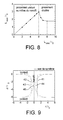
figure 9 est un diagramme représentant l'évolution du profil de la surface d'un nanofil libre pendant un recuit, en fonction du temps t, du rayon initial du nanofil r0 et du coefficient B, pour Lwire=6 r0, - la
figure 10 est un diagramme représentant le profil de la surface d'un nanofil libre de longueur Lwire=6 r0, avant et après recuit pendant un temps t=0,97 r0 4/B, - la
figure 11 est un diagramme représentant l'évolution du profil de la surface d'un nanofil libre pendant un recuit, en fonction du temps t, du rayon initial du nanofil r0 et du coefficient B, pour Lwire=7 r0, - les
figures 12 et 13 sont des diagrammes représentant le profil de la surface d'un nanofil libre de longueur Lwire=7 r0, avant et après un recuit pendant un temps t=1,4 r0 4/B, - les
figures 14A et 14B représentent des zones de rattachement entre des nanofils et leur contact correspondant, selon l'art connu (figure 14A ) et selon l'invention (14B), - la
figure 15 est un graphe représentant le minimum du rayon du nanofil au niveau du pincement, rneck, en fonction du temps t, du coefficient B et du rayon initial du nanofil r0, pour les géométries représentées auxfigures 14A et 14B .
- the
figure 1 , already described, shows a nanowire transistor structure according to the known art during manufacture, - the
figure 2 , already described, shows the nanowire transistor structure of thefigure 1 at a later stage of manufacture, according to the known art, - the
figure 3 , already described, shows the nanowire transistor structure of thefigure 2 completed by the formation of a grid, according to the known art, - the
Figures 4A to 4C , already described, are top views of a bar-supporting substrate for forming a nanowire, the ends of which are connected to drain and source, illustrating the migration phenomenon of the nanowire atoms being formed, - the
Figure 5A takes over the structure represented inFigure 4A and theFigure 5B shows the pinch effect due to annealing on a detail of theFigure 5A , - the
figure 6 is a graph representing the quantization of the pinch as a function of time, - the
figure 7 represents the MoveFilm numerical code algorithm applied to a free nanowire, - the
figure 8 is a graph representing the distance L neck between the nip and the contact according to the length of the nanowire and its initial radius r 0 , - the
figure 9 is a diagram representing the evolution of the surface profile of a free nanowire during an annealing, as a function of time t, of the initial radius of the nanowire r 0 and the coefficient B, for L wire = 6 r 0 , - the
figure 10 is a diagram representing the profile of the surface of a free nanowire of length L wire = 6 r 0 , before and after annealing for a time t = 0.97 r 0 4 / B, - the
figure 11 is a diagram representing the evolution of the surface profile of a free nanowire during an annealing, as a function of time t, of the initial radius of the nanowire r 0 and the coefficient B, for L wire = 7 r 0 , - the
Figures 12 and 13 are diagrams representing the surface profile of a free nanowire of length L wire = 7 r 0 , before and after annealing for a time t = 1.4 r 0 4 / B, - the
Figures 14A and 14B represent zones of attachment between nanowires and their corresponding contact, according to the known art (figure 14A ) and according to the invention (14B), - the
figure 15 is a graph representing the minimum of the nanowire radius at the nip, r neck , as a function of time t, the coefficient B and the initial radius of the nanowire r 0 , for the geometries represented atFigures 14A and 14B .
La maîtrise du dimensionnement du pincement du nanofil lors du recuit s'appuie sur des simulations par l'outil numérique « MoveFilm » développé au Commissariat à l'Energie Atomique. Les bases de ce code numérique appliqué à des films sont exposées dans l'article
Ce code a été modifié pour pouvoir simuler les effets du recuit (arrondissement et pincement) sur des nanofils libres (présentant une symétrie de rotation) et ainsi prévoir le dimensionnement du pincement en fonction des conditions expérimentales à savoir le type de matériau et les conditions du recuit (température du recuit, temps du recuit, nature du gaz et pression du gaz). L'effet de pincement simulé par « MoveFilm » est présenté sur la
Les graphes des
Au premier instant du recuit, le barreau passe d'une section carrée ou rectangulaire à une section circulaire. r0 représente le rayon de la section du nanofil circulaire avant pincement. L'invention porte sur l'évolution de cette section circulaire.At the first moment of annealing, the bar passes from a square or rectangular section to a circular section. r 0 represents the radius of the section of the circular nanowire before clamping. The invention relates to the evolution of this circular section.
La
La
Les grandeurs caractéristiques sont : r0 qui représente le rayon initial du fil, rneck qui représente le rayon du fil au niveau de la zone de constriction (pincement) et Lneck qui représente la distance de la zone de constriction par rapport à la position initiale du bord de la zone de contact la plus proche.The characteristic quantities are: r 0 which represents the initial radius of the wire, r neck which represents the radius of the wire at the level of the constriction zone (pinching) and L neck which represents the distance of the constriction zone with respect to the position from the edge of the nearest contact area.
La
On va exposer maintenant les détails du code appliqué à la simulation de l'effet de recuit des nanofils. Cet outil numérique simule l'évolution de la surface du nanofil et des contacts par diffusion de surface. Les détails du code numérique appliqué à des films sont décrits dans l'article de E. DORNEL et al. cité plus haut. On va détailler les étapes principales de l'outil numérique MoveFilm appliqué au nanofil libre présentant un axe de symétrie par rotation. La surface est discrétisée en points de coordonnées (r,z) où r est la distance à l'axe de symétrie z du nanofil. L'algorithme de ce code numérique consiste en une succession de 5 étapes : calcul des potentiels µi en chaque point, calcul des flux de matière Ji entre chaque point Mi et Mi+1, calcul des incréments de matière δNi attribués en chaque point Mi, puis les points sont déplacés et enfin le temps est incrémenté d'un pas de temps dt (voir la
Soit (ri-1,zi-1), (ri,zi) et (ri+1, zi+1) les coordonnées respectives des points Mi-1, Mi et Mi+1 de la surface. Les calculs de ces grandeurs (c'est-à-dire potentiels, flux, incréments de matière et déplacement) ont été reformulés par rapport à l'enseignement de l'article de E. DORNEL et al. cité plus haut. Le potentiel µi est calculé comme le rapport de la variation de la surface sur la variation du volume, en imaginant une accrétion de matière locale au niveau du point Mi, soit : 


Le flux est proportionnel à la dérivée surfacique du potentiel, soit entre les points Mi et Mi+1 : 
L'incrément de matière δNi attribué au point Mi est déterminé par la conservation de la quantité de matière, ce qui revient à l'intégrale des flux traversant les cercles de la surface de cotes zi-1 et zi+1 : 
Les points Mi sont déplacés successivement, de façon à ce que ce déplacement engendre un incrément de matière égal à δNi. De plus, les points sont déplacés perpendiculairement à la courbe iso-volume. Les points Mi sont donc déplacés du vecteur (δri,δzi) tel que : 

où (Nr,i,Nz,i) sont les coordonnées du vecteur normal à la courbe iso-volume en Mi : 
where (N r, i , N z, i ) are the coordinates of the vector normal to the iso-volume curve in M i :
L'invention permet également la maîtrise de la localisation du pincement selon l'axe du nanofil, c'est-à-dire selon l'axe z.The invention also allows the control of the location of the nip along the axis of the nanowire, that is to say along the z axis.
Dans le cas d'un fil long (c'est-à-dire tel que Lwire>8 r0 (voir la
Dans la zone où Lwire est inférieure ou égale à 6 r0, le pincement est unique et est à équidistance des contacts. Cette zone est intéressante car elle permet l'alignement de la grille à équidistance des contacts, lieu où se trouve le rayon minimum du fil.In the area where L wire is less than or equal to 6 r 0 , the nip is unique and is equidistant from the contacts. This area is interesting because it allows the alignment of the grid equidistant contacts, where is the minimum radius of the wire.
Dans le cas où Lwire>6 r0, deux pincements sont créés, à proximité de chaque contact.In the case where L wire > 6 r 0 , two nips are created, near each contact.
La zone où 3,5 r0 ≤Lwire≤8 r0 est particulièrement intéressante dans la mesure où le ou les pincements créés se trouvent éloignés des contacts (c' est-à-dire Lneck > 1, 9 r0) par rapport au cas où le fil est long (c'est-à-dire d'une longueur supérieure à 8 ro).The area where 3.5 r 0 ≤L wire ≤8 r 0 is particularly interesting insofar as the created pinch or nips are distant from the contacts (ie L neck > 1, 9 r 0 ) by relative to the case where the wire is long (that is to say of a length greater than 8 ro).
L'invention permet également la maîtrise de la localisation du pincement sur le nanofil. On va détailler les cas où 3,5 r0 ≤Lwire≤ 6 r0 et où 6 r0 <Lwire≤ 8 r0.
Cas où 3,5 r0 ≤ Lwire ≤ 6 r0 The invention also allows the control of pinch location on the nanowire. We go detail the cases where 3.5 r 0 ≤L wire ≤ 6 r 0 and where 6 r 0 <L wire ≤ 8 r 0 .
Case where 3.5 r 0 ≤ L wire ≤ 6 r 0
Les
Au final, on obtient un amincissement des fils au centre de l'espace situé entre les zones de source et de drain, en utilisant une technique connue qui est le recuit (voir les
Sur la
La
Cas où 6r0 < Lwier ≤ 8 r0 The
Case where 6r 0 <L wier ≤ 8 r 0
La
Sur la
Dans la zone 6 r0 <Lwire≤ 8 r0, le pincement est double et est éloigné du contact par rapport au cas où Lwire est très grand devant r0. L'avantage d'avoir un Lneck grand a déjà été discuté. L'avantage d'avoir dans ce cas deux pincements tout en ayant Lneck grand, est de pouvoir disposer de deux zones où le fil présente un rayon réduit, pour par exemple fabriquer deux grilles indépendantes et pouvoir contrôler la quantité de courant traversant le fil.In the zone 6 r 0 <L wire ≤ 8 r 0 , the nip is double and is away from the contact with respect to the case where L wire is very large in front of r 0 . The advantage of having a large L neck has already been discussed. The advantage of having in this case two nips while having L large neck , is to have two areas where the wire has a reduced radius, for example to manufacture two independent grids and to control the amount of current flowing through the wire .
Les
L'avantage d'avoir deux pincements proches l'un de l'autre est de pouvoir isoler une faible quantité de matière (la matière entre les deux pincements). Fabriquer une grille unique recouvrant les deux zones de pincements permettrait d'obtenir un effet de type transistor à un ou quelques électrons (voir la
Au final, on obtient un amincissement des nanofils au centre de l'espace situé entre les zones de source et de drain, en utilisant une technique connue qui est le recuit. Les avantages de l'invention sont donc une diminution locale de la cote du nanofil à deux endroits séparés par un endroit où le nanofil présente un rayon plus grand. De la sorte, le phénomène de pincement apparaît comme un avantage et non un inconvénient.In the end, thinning of the nanowires is obtained in the center of the space between the source and drain zones, using a known technique which is annealing. The advantages of the invention are therefore a local reduction of the nanowire dimension in two places separated by a place where the nanowire has a larger radius. In this way, the phenomenon of pinching appears as an advantage and not a disadvantage.
A partir des considérations précédentes et grâce à l'outil numérique utilisé par les inventeurs, ceux-ci sont parvenus à la conclusion que la modification de la courbure entre le nanofil et ses contacts permet de repousser le temps de rupture. Ceci est illustré par les
La
Cette
La modification de la géométrie proche des contacts permet ainsi de repousser le temps de rupture et permet à l'expérimentateur de choisir le temps et la température du recuit dans des plages moins contraignantes pour lesquelles la rupture n'est pas occasionnée par le recuit.The modification of the geometry close to the contacts thus makes it possible to postpone the break time and allows the experimenter to choose the annealing time and temperature in less restrictive areas for which the break is not caused by the annealing.
Un autre avantage est un gain sur la variabilité technologique. Par exemple, pour un temps de 0,5 r0 4/B une géométrie à 90° selon la
Claims (9)
Applications Claiming Priority (1)
| Application Number | Priority Date | Filing Date | Title |
|---|---|---|---|
| FR0758933A FR2923652B1 (en) | 2007-11-09 | 2007-11-09 | METHOD FOR MANUFACTURING PARALLEL NANOWILS WITH THEIR SUPPORT SUBSTRATE |
Publications (1)
| Publication Number | Publication Date |
|---|---|
| EP2058847A1 true EP2058847A1 (en) | 2009-05-13 |
Family
ID=39144329
Family Applications (1)
| Application Number | Title | Priority Date | Filing Date |
|---|---|---|---|
| EP08168359A Withdrawn EP2058847A1 (en) | 2007-11-09 | 2008-11-05 | Method of manufacturing nanowires parallel to their support substrate |
Country Status (3)
| Country | Link |
|---|---|
| US (1) | US8252636B2 (en) |
| EP (1) | EP2058847A1 (en) |
| FR (1) | FR2923652B1 (en) |
Cited By (1)
| Publication number | Priority date | Publication date | Assignee | Title |
|---|---|---|---|---|
| FR2995450A1 (en) * | 2012-09-11 | 2014-03-14 | Centre Nat Rech Scient | Logic gate e.g. NAND-type logic gate, for manufacturing part of locally constricted FET in digital electronic industry, has grid whose portion is positioned relative to zones so as to have field effect when channel is traversed by current |
Families Citing this family (3)
| Publication number | Priority date | Publication date | Assignee | Title |
|---|---|---|---|---|
| FR2910456B1 (en) * | 2006-12-21 | 2018-02-09 | Commissariat A L'energie Atomique | METHOD FOR PRODUCING MICROFILS AND / OR NANOWIAS |
| FR2910455B1 (en) * | 2006-12-21 | 2009-04-03 | Commissariat Energie Atomique | METHOD FOR PRODUCING NON-ALIGNED MICRO-CAVITIES AND DIFFERENT DEPTHS |
| US9048301B2 (en) | 2013-10-16 | 2015-06-02 | Taiwan Semiconductor Manufacturing Company Limited | Nanowire MOSFET with support structures for source and drain |
Citations (2)
| Publication number | Priority date | Publication date | Assignee | Title |
|---|---|---|---|---|
| US20050275010A1 (en) | 2004-06-10 | 2005-12-15 | Hung-Wei Chen | Semiconductor nano-wire devices and methods of fabrication |
| DE102006012416A1 (en) | 2005-03-24 | 2006-10-05 | Samsung Electronics Co., Ltd., Suwon | Field effect transistor fabrication involves etching and annealing nano-wire channel region extended between source and drain regions |
Family Cites Families (3)
| Publication number | Priority date | Publication date | Assignee | Title |
|---|---|---|---|---|
| US6855606B2 (en) * | 2003-02-20 | 2005-02-15 | Taiwan Semiconductor Manufacturing Company, Ltd. | Semiconductor nano-rod devices |
| WO2006085993A2 (en) * | 2004-07-16 | 2006-08-17 | The Trustees Of Boston College | Device and method for achieving enhanced field emission utilizing nanostructures grown on a conductive substrate |
| JP2006303451A (en) * | 2005-03-23 | 2006-11-02 | Renesas Technology Corp | Semiconductor device and method for manufacturing the same |
-
2007
- 2007-11-09 FR FR0758933A patent/FR2923652B1/en not_active Expired - Fee Related
-
2008
- 2008-11-05 EP EP08168359A patent/EP2058847A1/en not_active Withdrawn
- 2008-11-07 US US12/267,431 patent/US8252636B2/en active Active
Patent Citations (2)
| Publication number | Priority date | Publication date | Assignee | Title |
|---|---|---|---|---|
| US20050275010A1 (en) | 2004-06-10 | 2005-12-15 | Hung-Wei Chen | Semiconductor nano-wire devices and methods of fabrication |
| DE102006012416A1 (en) | 2005-03-24 | 2006-10-05 | Samsung Electronics Co., Ltd., Suwon | Field effect transistor fabrication involves etching and annealing nano-wire channel region extended between source and drain regions |
Non-Patent Citations (8)
| Title |
|---|
| E. DORNEL ET AL.: "Surface diffusion dewetting of thin solid films : Numerical method and application to Si/Si02", PHYSICAL REVIEW B, vol. 73, 2006, pages 115 - 427 |
| G. PENNELLI ET AL.: "Microelectronic Engineering", vol. 83, April 2006, ELSEVIER PUBLISHERS B.V., article "Silicon single-electron transistor fabricated by anisotropic etch and oxidation", pages: 1710 - 1713 |
| K. SUDOH ET AL.: "Numerical Study on Shape Transformation of Silicon Trenches by High-Temperature Hydrogen Annealing", JAP. J. OF APPL. PHYS., vol. 43, no. 9, 2004, pages 5937 - 5941 |
| LEI ZHUANG ET AL.: "Silicon single-electron quantum-dot transistor switch operating at room température", APPLIED PHYSICS LETTERS, vol. 72, no. 10, 9 March 1998 (1998-03-09), pages 1205 - 1207, XP012019779, DOI: doi:10.1063/1.121014 |
| PENNELLI ET AL: "Silicon single-electron transistor fabricated by anisotropic etch and oxidation", MICROELECTRONIC ENGINEERING, ELSEVIER PUBLISHERS BV., AMSTERDAM, NL, vol. 83, no. 4-9, April 2006 (2006-04-01), pages 1710 - 1713, XP005426921, ISSN: 0167-9317 * |
| TAKAHASHI YASUO ET AL: "Multigate single-electron transistors and their application to an exclusive-OR gate", APPLIED PHYSICS LETTERS, AIP, AMERICAN INSTITUTE OF PHYSICS, MELVILLE, NY, US, vol. 76, no. 5, 31 January 2000 (2000-01-31), pages 637 - 639, XP012025796, ISSN: 0003-6951 * |
| YASUO TAKAHASHI ET AL.: "Multigate single-electron transistors and their application to an exclusive-OR gate", APPLIED PHYSICS LETTERS, vol. 76, no. 5, 31 January 2000 (2000-01-31), pages 637 - 639, XP012025796, DOI: doi:10.1063/1.125843 |
| ZHUANG LEI ET AL: "Silicon single-electron quantum-dot transistor switch operating at room temperature", APPLIED PHYSICS LETTERS, AIP, AMERICAN INSTITUTE OF PHYSICS, MELVILLE, NY, US, vol. 72, no. 10, 9 March 1998 (1998-03-09), pages 1205 - 1207, XP012019779, ISSN: 0003-6951 * |
Cited By (1)
| Publication number | Priority date | Publication date | Assignee | Title |
|---|---|---|---|---|
| FR2995450A1 (en) * | 2012-09-11 | 2014-03-14 | Centre Nat Rech Scient | Logic gate e.g. NAND-type logic gate, for manufacturing part of locally constricted FET in digital electronic industry, has grid whose portion is positioned relative to zones so as to have field effect when channel is traversed by current |
Also Published As
| Publication number | Publication date |
|---|---|
| US20090124050A1 (en) | 2009-05-14 |
| FR2923652B1 (en) | 2010-06-11 |
| US8252636B2 (en) | 2012-08-28 |
| FR2923652A1 (en) | 2009-05-15 |
Similar Documents
| Publication | Publication Date | Title |
|---|---|---|
| Durkan et al. | Analysis of failure mechanisms in electrically stressed Au nanowires | |
| EP2299493B1 (en) | Fabrication of silicon and germanium nanowires integrated on a substrate | |
| EP2043141B1 (en) | Double-gate transistor structure equipped with a channel with several branches | |
| US8557613B2 (en) | Methods for designing, fabricating, and predicting shape formations in a material | |
| EP1889296A1 (en) | Channel transistor based on germanium encased by a gate electrode and method for producing this transistor | |
| EP1959481B1 (en) | Method of manufacturing a transistor | |
| WO2012069606A2 (en) | Process for fabricating a field-effect transistor device implemented on a network of vertical nanowires, the resulting transistor device, an electronic device comprising such transistor devices and a processor comprising at least one such device | |
| WO2011154360A2 (en) | Integrated circuit having a junctionless depletion-mode fet device | |
| FR3033665A1 (en) | SINGLE ELECTRONIC TRANSISTOR AND METHOD FOR MAKING SAME | |
| FR2860341A1 (en) | METHOD FOR MANUFACTURING LOWERED LOWER MULTILAYER STRUCTURE | |
| EP2058847A1 (en) | Method of manufacturing nanowires parallel to their support substrate | |
| FR2762931A1 (en) | QUANTIC ILOTS DEVICE AND METHOD OF MANUFACTURE | |
| EP1346405A1 (en) | Method for making an island of material confined between electrodes, and application to transistors | |
| FR3056334A1 (en) | METHOD FOR INCREASING THE STRESS IN A SEMICONDUCTOR REGION FOR FORMING A TRANSISTOR CHANNEL | |
| Webb et al. | Imaging atomic scale dynamics on III–V nanowire surfaces during electrical operation | |
| WO2000057480A1 (en) | Novel semiconductor device combining the advantages of solid and soi architectures, and method for making same | |
| EP3688674B1 (en) | Method of producing a recurrent neural network computer | |
| EP1042818A1 (en) | C | |
| EP3867192A1 (en) | Method and device for depositing a nano-object | |
| Cronin et al. | Electronic properties of Bi nanowires | |
| FR2995450A1 (en) | Logic gate e.g. NAND-type logic gate, for manufacturing part of locally constricted FET in digital electronic industry, has grid whose portion is positioned relative to zones so as to have field effect when channel is traversed by current | |
| FR2998091A1 (en) | METHOD FOR PREPARING A SAMPLE SAMPLE FOR TOMOGRAPHIC PROBE ANALYSIS OF ELECTRONIC STRUCTURES | |
| EP2148373B1 (en) | Method for applying simultaneous tensile and compressive stress to NMOS and PMOS transistor channels respectively | |
| EP3420412B1 (en) | Method for electronic lithography with electrostatic screening | |
| Pagliano et al. | Feedback-free electromigrated tunneling junctions from crack-defined gold nanowires |
Legal Events
| Date | Code | Title | Description |
|---|---|---|---|
| PUAI | Public reference made under article 153(3) epc to a published international application that has entered the european phase |
Free format text: ORIGINAL CODE: 0009012 |
|
| AK | Designated contracting states |
Kind code of ref document: A1 Designated state(s): AT BE BG CH CY CZ DE DK EE ES FI FR GB GR HR HU IE IS IT LI LT LU LV MC MT NL NO PL PT RO SE SI SK TR |
|
| AX | Request for extension of the european patent |
Extension state: AL BA MK RS |
|
| 17P | Request for examination filed |
Effective date: 20091026 |
|
| AKX | Designation fees paid |
Designated state(s): AT BE BG CH CY CZ DE DK EE ES FI FR GB GR HR HU IE IS IT LI LT LU LV MC MT NL NO PL PT RO SE SI SK TR |
|
| RAP1 | Party data changed (applicant data changed or rights of an application transferred) |
Owner name: COMMISSARIAT A L'ENERGIE ATOMIQUE ET AUX ENERGIES |
|
| STAA | Information on the status of an ep patent application or granted ep patent |
Free format text: STATUS: THE APPLICATION IS DEEMED TO BE WITHDRAWN |
|
| 18D | Application deemed to be withdrawn |
Effective date: 20150602 |