EP2058665A2 - Analyzer - Google Patents
Analyzer Download PDFInfo
- Publication number
- EP2058665A2 EP2058665A2 EP08019617A EP08019617A EP2058665A2 EP 2058665 A2 EP2058665 A2 EP 2058665A2 EP 08019617 A EP08019617 A EP 08019617A EP 08019617 A EP08019617 A EP 08019617A EP 2058665 A2 EP2058665 A2 EP 2058665A2
- Authority
- EP
- European Patent Office
- Prior art keywords
- application program
- area
- country
- memory
- analysis
- Prior art date
- Legal status (The legal status is an assumption and is not a legal conclusion. Google has not performed a legal analysis and makes no representation as to the accuracy of the status listed.)
- Withdrawn
Links
Images



Classifications
-
- G—PHYSICS
- G01—MEASURING; TESTING
- G01N—INVESTIGATING OR ANALYSING MATERIALS BY DETERMINING THEIR CHEMICAL OR PHYSICAL PROPERTIES
- G01N35/00—Automatic analysis not limited to methods or materials provided for in any single one of groups G01N1/00 - G01N33/00; Handling materials therefor
- G01N35/00584—Control arrangements for automatic analysers
-
- G—PHYSICS
- G01—MEASURING; TESTING
- G01N—INVESTIGATING OR ANALYSING MATERIALS BY DETERMINING THEIR CHEMICAL OR PHYSICAL PROPERTIES
- G01N35/00—Automatic analysis not limited to methods or materials provided for in any single one of groups G01N1/00 - G01N33/00; Handling materials therefor
- G01N35/00584—Control arrangements for automatic analysers
- G01N35/00722—Communications; Identification
-
- G—PHYSICS
- G01—MEASURING; TESTING
- G01N—INVESTIGATING OR ANALYSING MATERIALS BY DETERMINING THEIR CHEMICAL OR PHYSICAL PROPERTIES
- G01N35/00—Automatic analysis not limited to methods or materials provided for in any single one of groups G01N1/00 - G01N33/00; Handling materials therefor
- G01N35/00584—Control arrangements for automatic analysers
- G01N35/00722—Communications; Identification
- G01N2035/00891—Displaying information to the operator
- G01N2035/0091—GUI [graphical user interfaces]
-
- G—PHYSICS
- G01—MEASURING; TESTING
- G01N—INVESTIGATING OR ANALYSING MATERIALS BY DETERMINING THEIR CHEMICAL OR PHYSICAL PROPERTIES
- G01N2203/00—Investigating strength properties of solid materials by application of mechanical stress
- G01N2203/02—Details not specific for a particular testing method
- G01N2203/026—Specifications of the specimen
- G01N2203/0262—Shape of the specimen
- G01N2203/0266—Cylindrical specimens
-
- G—PHYSICS
- G01—MEASURING; TESTING
- G01N—INVESTIGATING OR ANALYSING MATERIALS BY DETERMINING THEIR CHEMICAL OR PHYSICAL PROPERTIES
- G01N35/00—Automatic analysis not limited to methods or materials provided for in any single one of groups G01N1/00 - G01N33/00; Handling materials therefor
- G01N35/00584—Control arrangements for automatic analysers
- G01N35/00722—Communications; Identification
- G01N35/00871—Communications between instruments or with remote terminals
-
- G—PHYSICS
- G06—COMPUTING OR CALCULATING; COUNTING
- G06F—ELECTRIC DIGITAL DATA PROCESSING
- G06F9/00—Arrangements for program control, e.g. control units
- G06F9/06—Arrangements for program control, e.g. control units using stored programs, i.e. using an internal store of processing equipment to receive or retain programs
- G06F9/44—Arrangements for executing specific programs
- G06F9/451—Execution arrangements for user interfaces
- G06F9/454—Multi-language systems; Localisation; Internationalisation
Definitions
- the present invention relates to an analyzer and a method of restricting a function of an application program in an analyzer, and more particularly, it relates to an analyzer capable of functioning in specifications different for respective areas and a method of restricting a function of an application program in such an analyzer.
- U.S. Patent No. 7013260 discloses a sample analyzer allowing display by using a language for an area which a user demands.
- the analyzers have heretofore used in a plurality of areas, and only the analyzer used in a prescribed area among the plurality of areas is often provided with an additional function performing particular control.
- an application program for the prescribed area different from an application program for other areas is generally installed into the analyzer used in the prescribed area to perform the particular control for the prescribed area.
- the sample analyzer in a case where the application program for the prescribed area for performing the particular control for the prescribed area is installed into the sample analyzer, and the user hereafter installs the application program for other areas into the sample analyzer, the sample analyzer disadvantageously performs control for other areas when the user stars the application program for other areas. In other words, the sample analyzer disadvantageously does not perform the particular control for the prescribed area although used in the prescribed area, once the application program for other areas starts.
- a first aspect of the present invention is an analyzer, comprising: a measurement section for measuring a specimen and acquiring measurement data; a controller, including a first memory under control of a processor, the first memory storing instructions enabling the processor to carry out operations, comprising: analyzing the measurement data acquired by the measurement section and acquiring results of analysis; displaying the results of analysis acquired; and controlling at least one of measurement, analysis and display to be for a first area when a first application program for the first area starts, while controlling at least one of the measurement, the analysis and the display to be for a second area when a second application program for the second area starts; and a second memory enabled to memorize that the control by the controller is for the first area, wherein the controller controls at least one of the measurement, the analysis and the display to be for the first area when the second application program starts in a case where the second memory memorizes that the control by the controller is for the first area.
- a second aspect of the present invention is an analyzer comprising: installation accepting means for accepting installation of a first application program and a second application program acquiring results of analysis of specimen, wherein the first application program is for a first area and the second application program is for a second area; execution means for executing the first application program and the second application program; and restriction means for restricting at least a partial function of the second application program, when the installation accepting means accepts the installation of the first application program and the execution means thereafter executes the second application program.
- a third aspect of the present invention is a method of restricting a function of an application program in an analyzer, comprising steps of: accepting installation of a first application program acquiring results of analysis of specimen, wherein the first application program is for a first area; accepting installation of a second application program acquiring the results of analysis of the specimen, wherein the second application program is for a second area; executing the second application program; and restricting at least a partial function of the second application program in a case where the installation of the first application program has been accepted.
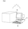
- a urinary particle analyzer 1 according to an embodiment of the present invention will be now described with reference to Figs. 1 to 4 .
- the urinary particle analyzer 1 is constituted by a measuring apparatus 2 optically measuring particles contained in urine by a flow cytometer and a control apparatus 3 processing a measurement value output from the measuring apparatus 2 to obtain the results of analysis, as shown in Fig. 1 .
- the measuring apparatus 2 is provided with a specimen distribution section 201, a sample preparation section 202, and an optical detecting section 203, an analog signal processing circuit 204 for executing amplification of output by the optical detecting section 203 and filter processing, an A/D converter 205 for converting output of the analog signal processing circuit 204 to digital signals and a digital signal processing circuit 206 for executing a predetermined waveform processing for digital signals.
- the measuring apparatus 2 is provided with a memory 207 connected to the digital signal processing circuit 206, a CPU 208 connected to the analog signal processing circuit 204 and the digital signal processing circuit 206 and a LAN adapter 209 connected to the CPU 208.
- the control apparatus 3 is LAN connected to the measuring apparatus 2 through the LAN adapter 209.
- the analog signal processing circuit 204, the A/D converter 205, the digital signal processing circuit 206 and the memory 207 constitutes a signal processing circuit 210 for electric signals being output by the optical detecting section 203.
- the measuring apparatus 2 is provided with a memory 211 such as a BBURAM (battery backup RAM) connected to the CPU 208, and the like.
- BBURAM battery backup RAM
- the specimen distribution section 201 is so formed that a prescribed distributed quantity of urine (specimen) is dispensed to the sample preparation section 202.
- the sample preparation section 202 is so formed as to prepare a measurement sample from the urine (specimen) dispensed by the specimen distribution section 201 and a reagent and supply the prepared measurement sample to a sheath flow cell 203c (see Fig. 3 ), described later, of the optical detecting section 203 together with sheath fluid.
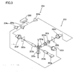
- the optical detecting section 203 includes a light emitting section 203a for emitting a laser beam, an illumination lens unit 203b, a sheath flow cell 203c for applying the laser beam, a condensing lens 203d, a pinhole 203e and a PD (photodiode) 203f arranged on an extension line of a traveling direction of the laser beam emitted from the light emitting section 203a, a condensing lens 203g, a dichroic mirror 203h, an optical filter 203i, a pinhole plate 203j having a pinhole and a PMT (Photomultiplier) 203k arranged in a direction intersecting with the traveling direction of the laser beam emitted from the light emitting section 203a, and a PD 2031 arranged in a lateral direction of the dichroic mirror 203h.
- a light emitting section 203a for emitting a laser beam
- an illumination lens unit 203b for applying the laser beam
- the light emitting section 203a is provided for emitting light with respect to the flow of the sample including the measurement sample passing through the inside of the sheath flow cell 203c.
- the illumination lens unit 203b is provided for parallelizing the light applied from the light emitting section 203a.
- the PD 203f is provided for receiving forward scattered light emitted from the sheath flow cell 203c.
- the dichroic mirror 203h is provided for separating side scattered light and side fluorescence emitted from the sheath flow cell 203c. More specifically, the dichroic mirror 203h is provided for introducing the side scattered light emitted from the sheath flow cell 203c into the PD 2031 and introducing the side fluorescence emitted from the sheath flow cell 203c to the PMT 203k.
- the PD 2031 is provided for receiving the side scattered light.
- the PMT 203k is provided for receiving the side fluorescence.
- the PDs 203f and 2031 and the PMT 203k have functions of converting the received light signals to electric signals respectively.
- the analog signal processing circuit 204 includes amplifiers 204a, 204b and 204c.
- the amplifiers 204a, 204b and 204c are provided for executing amplification and waveform processing for the electric signals output from the PDs 203f and 2031 and PMT 203k respectively.
- the memory 211 is so formed as to store information (determination result information) indicating whether or not a replaced new reagent is a dedicated reagent (genuine product). More specifically, a CPU 301a, described later, of the control apparatus 3 determines whether or not the newly replaced reagent is the dedicated reagent, and the memory 211 is so formed as to store the determination result information based on the results of the determination.
- the control apparatus 3 is formed by a personal computer (PC) or the like.
- the control apparatus 3 includes a control section 301, a display section 302 and an input device 303.
- the control apparatus 3 has a function of accepting an operation of the user, transmitting an instruction to the measuring apparatus 2, receiving measurement data (measurement value) from the measuring apparatus 2 and processing the measurement data to display results of analysis.
- the control section 301 is constituted by the CPU 301a, a ROM 301b, a RAM 301c, a hard disk 301d, a reader 301e, an input/output interface 301f, an image output interface 301g and a communication interface 301i.
- the CPU 301a, the ROM 301b, the RAM 301c, the hard disk 301d, the reader 301e, the input/output interface 301f, the image output interface 301g and the communication interface 301i are connected by a bus 301h.
- the CPU 301a is provided for executing computer programs recorded in the ROM 301b and computer programs loaded in the RAM 301c.
- the ROM 301b may be a mask ROM, a PROM, an EPROM, an EEPROM or the like, which stores computer programs executed by the CPU 301a and data used by these computer programs.
- the CPU 301a has a function of processing the measurement value measured by the measuring apparatus 2 to obtain results of analysis and outputting an image signal corresponding to an analytical result screen 500 (see Fig. 11 ) for displaying the results of analysis to the image output interface 301g.
- the CPU 301a When the user replaces a reagent used in the measuring apparatus 2, the CPU 301a outputs the image signal to the image output interface 301g so as to display a reagent replacement screen (not shown) on the display section 302.
- This reagent replacement screen is so formed that the user can input a unique reagent code of 27 characters attached to a reagent container (not shown).
- the reagent code is an encrypted reagent code of 27 characters for storing unique information such as a lot number for acquiring expiration date or traceability in the dedicated reagent (genuine product) adequate for measurement by the measuring apparatus 2.
- This reagent code is encrypted using a hash function such as MD (message digest algorithm) 5 and is so formed that the CPU 301a is capable of determining whether or not the replaced reagent is the dedicated reagent (genuine product) adequate for use in the measuring apparatus 2 on the bases of the encrypted alphanumeric characters of 27 characters.
- MD message digest algorithm
- the CPU 301a is so formed as to measure the residual quantity of a reagent in use and store the information of the residual quantity in the hard disk 301d together with the reagent code of the reagent.
- the hard disk 301d is capable of storing the reagent codes and the information of the residual quantity of a plurality of reagents which have been used in the past as a reagent replacement history.
- the CPU 301a is so formed as to determine whether or not the replaced new reagent is the dedicated reagent (genuine product) on the basis of both of the reagent code and the residual quantity.
- the RAM 301c is constituted by an SRAM or a DRAM.
- the RAM 301c is employed for reading the computer programs recorded in the ROM 301b and the hard disk 301d. Further, the RAM 301c is utilized as a working area of the CPU 301a when executing these computer programs.
- An operating system and various computer programs such as application programs to be executed by the CPU 301a as well as data employed for executing the computer programs are installed in the hard disk 301d.
- An application program 304a or 305a, described later, is also installed in this hard disk 301d.
- the reader 301e is formed by a flexible disk drive, a CD-ROM drive or a DVD-ROM drive, and can read computer programs or data recorded in portable recording mediums 304 and 305.
- the portable recording medium 304 stores the application program 304a for making the computer achieve a prescribed function and an installation program 304b for installing the application program 304a in the computer.
- the portable recording medium 305 stores the application program 305a for making the computer achieve a prescribed function and an installation program 305b for installing the application program 305a in the computer.
- the installation program 304b is started, the computer employed as the control apparatus 3 can read the application program 304a from the portable recording medium 304 and install the application program 304a in the hard disk 301d.
- the portable recording medium 305 is formed similarly to the portable recording medium 304.
- the portable recording medium 304 is provided for country A
- the portable recording medium 305 is provided for countries (country B, country C and country D, for example) other than country A.
- the application program 304a stored in the portable recording medium 304 and the application program 305a stored in the portable recording medium 305 are substantially the same application program.
- Each application program includes a program making the control apparatus 3 execute control for country A and control for the countries (country B, country C and country D, for example) other than country A.
- each of the application programs 304a and 305a includes a specimen analysis program for transmitting a measurement start signal, analyzing a received measurement value and displaying the results of analysis and a restriction program for restricting a partial function of the specimen analysis program.
- the specimen analysis program normally makes the control apparatus 3 execute the control for the countries other than country A while making the control apparatus 3 execute the control for country A when the control program restricts the partial function of the specimen analysis program.
- the aforementioned application programs 304a and 305a are provided not only by the portable recording mediums 304 and 305 respectively, but can be provided also from an external apparatus communicably connected with the computer by an electric communication line (whether wire or wireless) through the aforementioned electric communication line.
- an electric communication line whether wire or wireless
- the aforementioned application program 304a or 305a is stored in a hard disk of a server computer on the Internet, so that the computer accesses this server computer, downloads the application program 304a or 305a and installs the same in the hard disk 301d.
- the operating system such as Windows (registered trademark) manufactured and sold by Microsoft, U.S.A., providing graphical user interface environment is installed in the hard disk 301d.
- Windows registered trademark
- the application programs 304a and 305a according to this embodiment operate on the aforementioned operating system.
- the output interface 301f is constituted by a serial interface such as USB, IEEE 1394 or RS-232C, a parallel interface such as SCSI, IDE or IEEE 1284, an analog interface formed by a D/A converter, an A/D converter etc. or the like, for example.
- the input device 303 including a keyboard and a mouse is connected to the input/output interface 301f, so that the user can input data into the control apparatus 3 by using the input device 303.
- An output device 306 including a printer and the like is connected to the input/output interface 301f.
- the communication interface 301i is Ethernet (registered trademark) interface, and a data processing apparatus 3 is capable of transmitting and receiving data to and from the measuring apparatus 2 connected by a LAN cable using a prescribed communication protocol (TCP/IP) by means of this communication interface 301i.
- TCP/IP prescribed communication protocol
- the image output interface 301g is connected to the display section 302 formed by an LCD, CRT or the like, so that an image signal received from the CPU 301a is output to the display section 302.
- the display section 302 displays images (screens) in accordance with the input image signal.
- the portable recording medium 304 is set in the reader 301e (see Fig. 4 ) of the control apparatus 3 and the CPU 301a thereafter determines whether or not the user has started the installation program 304b. This determination is repeated when no start instruction by the user is made, while the installation program 304b is started at a step S2 when the start instruction is made.
- the installation program 304b may be so formed as to be automatically started with no instruction by the user when the reader 301e reads the contents of the portable recording medium 304. Then the control apparatus 3 is automatically set to a specification for country A at a step S3, and the application program 304a is installed into the hard disk 301d at a step S4.
- the application program 304a is started in a state where the control apparatus 3 is set to the specification of the country A.
- specifications for country B, country C and country D are indicated as described later in addition to the aforementioned specification for country A, and layouts of the analytical result screens or output formats of the respective specifications are different from each other so as to correspond to laws or customs of the respective countries.
- the urinary particle analyzer 1 according to this embodiment is so formed that the user can select a preferable display language from a plurality of languages such as Japanese, English and Chinese. Even when any specification described above has been set, the user can select any display language. Thereafter the operation is ended.
- the portable recording medium 305 is first set in the reader 301e (see Fig. 4 ) of the control apparatus 3 and the CPU 301a thereafter determines whether or not the user has started the installation program 305b. This determination is repeated when no start instruction by the user is made, while the installation program 305b is started at a step S12 when the start instruction is made. Then the CPU 301a determines whether or not the user has selected a destination country at a step S13.
- the user can select the destination country from a destination country selection screen (not shown) so as to set the control apparatus 3 to a specification for any one of country B, country C and country D other than country A.
- step S13 The determination of the step S13 is repeated until the user selects the destination country.
- the control apparatus 3 is set to a specification for the selected country at a step S14, and the application program 305a is installed into the hard disk 301d at a step S15.
- the application program 305a is started in a state where the control apparatus 3 is set to the specification for the country selected by the user. Thereafter the operation is ended.
- the control apparatus 3 it is determined whether or not the reagent has been replaced at a step S101 in Fig. 7 , and this determination is repeated when the reagent is not replaced.
- a signal of the determination result information obtained by determining whether or not the replaced reagent is the genuine product is transmitted to the measuring apparatus 2 at a step S102 and the operation is ended.
- the CPU 301a determines it on the bases of the reagent code unique to each reagent input when replaced.
- sequence control in reagent replacement is a preparatory operation for performing the next measurement. More specifically, when the reagent is replaced, air is leaked into a tube through which the reagent flows or no reagent exists in the space of the tube where the reagent should normally exist. In order to prevent this situation, the reagent is sucked from a newly set reagent container into the tube so that the reagent fills up the tube in the sequence control in reagent replacement.
- the memory 211 stores information as to whether or not the replaced reagent is the dedicated reagent (genuine product) on the basis of the received signal of the determination result information. More specifically, the genuine product flag stored in the memory 211 is updated to be turned on when the replaced reagent is the dedicated reagent (genuine product), while the genuine product flag is updated to be turned off when the replaced reagent is a nondedicated reagent (non-genuine product). Thereafter, the operation of the measuring apparatus 2 is ended.
- a reagent information signal is transmitted to the control apparatus 3 on the basis of a state of the genuine product flag stored in the memory 211 (see Fig. 2 ) of the measuring apparatus 2 at a step S211 in Fig. 8 . More specifically, the control apparatus 3 receives a signal indicating that the reagent to be used is the dedicated reagent (genuine product) when the genuine product flag is in an ON-state, while the control apparatus 3 receives a signal indicating that the reagent to be used is the nondedicated reagent (non-genuine product) and the operation is ended when the genuine product flag is in an OFF-state.
- the reagent information signal transmitted from the measuring apparatus 2 is received at a step S111, and the CPU 301a (see Fig. 4 ) confirms whether or not the reagent to be used is the dedicated reagent (genuine product) on the basis of the received reagent information signal at a step S112. While the operation is ended when the reagent to be used is the dedicated reagent (genuine product), a warning screen 400 is displayed at a step S113 as shown in Fig. 9 when the reagent to be used is the nondedicated reagent (non-genuine product).
- the warning screen 400 the warning indicating that the reagent code is not correctly input when the reagent is replaced and the results of analysis can not be ensured is displayed. Thereafter an operation of the control apparatus 3 is ended. This operation is performed when the urinary particle analyzer 1 starts.
- the CPU 301a transmits, to the measuring apparatus 2, the control apparatus specification information as to the country of the specification to which the control apparatus 3 is set at a step S121 in Fig. 10 .
- a background of a screen to be displayed on the display section 302 is displayed in red when the user starts the application program 304a for country A, the background of the screen is displayed in blue when the user starts the application program 305a for the countries other than country A.
- the CPU 208 determines whether or not the control apparatus specification information transmitted from the control apparatus 3 has been received at a step S221, and this determination is repeated until the control apparatus specification information is received.
- the CPU 208 determines whether or not the control apparatus 3 is under the specification for country A on the basis of the received control apparatus specification information at a step S222.
- the CPU 208 stores the information indicating the control apparatus 3 is under the specification for country A in the memory 211 such as BBURAM (battery backup RAM) at a step S223.
- BBURAM battery backup RAM
- the CPU 208 updates to bring a specification flag for country A into an ON-state and the specification flag for country A is stored in the memory 211.
- this specification flag for country A is stored in the memory 211 so as to be unable to return to an OFF-state once the specification flag is updated to be brought into the ON-state. Therefore, when the application program 304a for country A is installed into the control apparatus 3, the specification flag for country A is set to the ON-state in the memory 211 of the measuring apparatus 2 and, then the ON-state of the specification flag for country A in the memory 211 is not returned to an OFF-state even when the application program 305a for the countries other than country A is installed into the control apparatus 3 in an overwrite manner.
- the operation advances to a step S224 without updating to bring the specification flag for country A into the ON-state.
- the CPU 208 transmits the state information of the specification flag for country A from the measuring apparatus 2 to the control apparatus 3. In other words, information as to whether the specification flag for country A stored in the memory 211 of the measuring apparatus 2 is in the ON-state or the OFF-state is transmitted from the measuring apparatus 2 to the control apparatus 3.
- the CPU 301a determines whether or not the state information of the specification flag for country A transmitted from the measuring apparatus 2 has been received at a step S122. This determination is repeated until specification flag state information is received.
- the CPU 301a determines whether or not the specification flag for country A of the measuring apparatus 2 is in an ON-state at a step S123.
- a restriction function is set to an ON-state in the application program 304a (305a) so as to activate particular restriction for country A described later at a step S124. Even when the application program 305a for the countries other than country A has started, the particular restriction function for country A is set to the ON-state at a step S124.
- the application program 304a for country A is first installed into the control apparatus 3 and the specification flag for country A of the measuring apparatus 2 is updated to be brought into the ON-state and the application program 305a for the countries other than country A is thereafter installed into the control apparatus 3 in an overwrite manner, for example, the particular restriction function for country A (output restriction function of the results of analysis) is activated although the control apparatus 3 is under the specification for country B, country C or country D. Further, once the application program 304a for country A is installed, the particular restriction function for country A (output restriction function of the results of analysis) is activated even when the application program 305a for the countries other than country A is started. In a case where the application program 304a for country A has never installed, the particular restriction function for country A (output restriction function of the results of analysis) is not activated when the application program 305a for the countries other than country A is started.
- the CPU 301a determines whether or not an instruction of measurement start from the user has been made at a step S125.
- the CPU 301a transmits a signal of the measurement start to the measuring apparatus 2 at a step S126.
- the CPU 208 determines whether or not the signal of the measurement start transmitted from the control apparatus 3 has been received at a step S225.
- the measuring apparatus 2 starts measuring urinary particles at a step S226.
- this determination is repeated while continuing the measurement.
- measurement value data is transmitted to the control apparatus 3 through the LAN adapter 209 at a step S228 and the operation in the measuring apparatus 2 is ended.
- the measurement value data transmitted from the measuring apparatus 2 is received at a step S127, and the measurement value processing (analysis processing) is performed on the basis of the received measurement value data at a step S128.
- the CPU 301a determines whether or not the particular restriction function for country A is set to an ON-state at a step S129, and the operation advances to a step S132 when the particular restriction function for country A is not in the ON-state.
- the CPU 301a determines whether or not the used reagent is the dedicated reagent (genuine product) on the basis of the state of the genuine product flag stored in the memory 211 at a step S130.
- the analytical result screen (not shown) is displayed at a step S132 and the operation is ended.
- a partial function of a display program of the specimen analysis program included in the application program 304a (305a) is restricted on the basis of the restriction program at a step S131 to perform the output restriction of the results of analysis, and the analytical result screen 500 subjected to the output restriction is displayed on the display section 302 at a step S132. More specifically, asterisks (*) on a display region 500a are appended in columns of all of base items on the analytical result screen 500 in a state of selecting a main tab 500c as shown in Fig. 11 .
- a display region 500b at the upper left of the analytical result screen 500 is displayed in red for rendering REVIEW display prominent, so that the user can easily recognize reexamination is desired for the specimen. Since the reliability of the results of analysis is low, all numerical data regarding research items on a less important display region 500d is hidden by hyphens (-) and scatter diagrams of a display region 500e are also hidden. Thus, the possibility that the urinary particle analyzer 1 provides the user with the results of analysis having low reliability can be reduced as small as possible.
- the base items are items relating to RBC (red blood cells), WBC (white blood cells), EC (epithelial cells), CAST (casts) and BACT (bacteria), research items are items relating to X'TAL (crystals), YLC (yeast-like fungi), SRC (small round cell), Path.
- CAST thinly cast including cell components
- MUCUS mocus fibril
- SPERM sperms
- Cond. urine conductivity
- operations at the steps S130 and S131 are operations by the particular restriction function for country A.
- the CPU 301a formed so as to control the display section 302 to the specification for country A when the application program 304a for country A starts while controlling the display section 302 to the specification for the countries other than country A when the application program 305a for the countries other than country A starts is provided, whereby the single CPU 301a can perform control for different countries.
- the CPU 301a is so formed as to perform the particular control for country A on display section 302 even when the application program 305a for the countries other than country A starts in a case where the memory 211 stores the information indicating the control by the CPU 301a is for country A, whereby when the urinary particle analyzer 1 is used in country A, the control for country A can be performed even when the user starts the application program 305a for the countries other than country A so far as the memory 211 stores the information that the control by the CPU 301a is for country A. In other words, this urinary particle analyzer 1 can perform the control for country A at the time of use in country A, even when the application program 305a for the countries other than country A is started.
- the CPU 301a controls the display section 302, so that the background of the screen is displayed in red when the application program 304a for country A is started, while the background of the screen is displayed in blue when the application program 305a for the countries other than country A is started, whereby the user can easily visibly confirm by the background color of the display section 302 which application program of the application program 304a for country A and the application program 305a for the countries other than country A is started.
- the program controlling the display section 302 for country A and the program controlling the display section 302 for countries other than country A are preferably provided in the application program 305a for the countries other than country A, whereby the control for country A can be performed also in a case application program 305a for the countries other than country A is started even when the application program 304a for country A is uninstalled and deleted from the inside of control apparatus 3 so far as the memory 211 stores the information indicating the control by the CPU 301a is for country A.
- the measuring apparatus 2 separated from the control apparatus 3 including the CPU 301a is provided with the memory 211, whereby the recorded contents of the memory 211 can be reliably preserved also when the control apparatus 3 is initialized (formatted) by the user and all of the recorded contents in the control apparatus 3 is deleted or also when the control apparatus 3 is replaced with another control apparatus.
- the control for country A can be reliably performed also when the application program 305a for countries (country B, country C and country D, for example) other than country A is started so far as the memory 211 stores the information indicating the control by the CPU 301a of the control apparatus is for country A.
- the present invention is not restricted to this but the present invention may be applied to another specimen analyzer such as a multiple hemocyte analyzer, a blood coagulation measuring apparatus and an immunoanalyzer.
- restriction for country A is the output restriction of the results of analysis displayed on the display section in the aforementioned embodiment
- the present invention is not restricted to this but the restriction may be restriction for not measuring the research items in the measuring apparatus or restriction for not analyzing the research items in the control apparatus, for example.
- the specification of the control apparatus While when the specification flag for country A of the measuring apparatus is in the ON-state, the specification of the control apparatus remains unchanged and only the particular restriction function for country A is set to the ON-state in the aforementioned embodiment, the present invention is not restricted to this but the specification of the control apparatus may be set to the specification for country A in addition of setting the particular restriction function for country A to the ON-state when the specification flag for country A of the measuring apparatus is in the ON-state.
- the present invention is not restricted to this but the display section 302 is so controlled that a display mode in a case where the application program 304a starts and a display mode in a case where the application program 305a starts are different from each other.
- a part of a window displayed on the display section or color of a title bar may be changed or display color may be changed by providing a display device such as LED on the control apparatus 3 in order to distinguish types of the application programs.
- the control may be changed between countries A and B and countries other than countries A and B.
- the control apparatus is not the specification for country A at the step S222 in Fig. 10 (NO at the step S222), and it is thereafter determined whether or not the control apparatus is for country B.
- the specification flag for country B is updated to be brought into an ON-state in the memory 207. Then the information indicating that the specification flag for country B is in the ON-state is transmitted at the step S224. Further, the CPU 301a in the control apparatus executes the results of analysis output restriction for country B at the step S131.
- the specification of the control apparatus can not be changed to the specification for countries other than countries A and B once the application program for country A is installed, and the specification of the control apparatus can not be changed to the specification for countries other than countries A and B once the application program for country B is installed.
- control for country A is executed when the application program for country B or country D is installed and the application program for country A is thereafter installed in the aforementioned embodiment
- the control for country B or country D first installed may be executed also when the application program for country B or country D is installed and the application program for country A is thereafter installed.
- the control apparatus is not the specification for country A at the step S222 in Fig. 10 (No at the step S222) and it is thereafter determined whether or not the control apparatus is for B country.
- the specification flag for country B is updated to be brought into the ON-state in the memory 207. Thereafter the ON-state of the specification flag for country B is not changed even when the application program for country A is installed. In other words, the specification flag for country A is simply not updated to be brought into the ON-state when the specification flag for country B is in the ON-state at the step S223.
Landscapes
- General Health & Medical Sciences (AREA)
- Health & Medical Sciences (AREA)
- Life Sciences & Earth Sciences (AREA)
- Chemical & Material Sciences (AREA)
- Analytical Chemistry (AREA)
- Biochemistry (AREA)
- Physics & Mathematics (AREA)
- General Physics & Mathematics (AREA)
- Immunology (AREA)
- Pathology (AREA)
- Automatic Analysis And Handling Materials Therefor (AREA)
- Investigating Or Analysing Biological Materials (AREA)
- Analysing Materials By The Use Of Radiation (AREA)
Abstract
Description
- The present invention relates to an analyzer and a method of restricting a function of an application program in an analyzer, and more particularly, it relates to an analyzer capable of functioning in specifications different for respective areas and a method of restricting a function of an application program in such an analyzer.
- An analyzer capable of functioning in specifications different for respective area is known in general, as disclosed in
U.S. Patent No. 7013260 , for example. - The aforementioned
U.S. Patent No. 7013260 discloses a sample analyzer allowing display by using a language for an area which a user demands. - The analyzers have heretofore used in a plurality of areas, and only the analyzer used in a prescribed area among the plurality of areas is often provided with an additional function performing particular control. In this case, an application program for the prescribed area different from an application program for other areas is generally installed into the analyzer used in the prescribed area to perform the particular control for the prescribed area.
- In the use of the aforementioned sample analyzer described in
U.S. Patent No. 7013260 in the prescribed area, however, in a case where the application program for the prescribed area for performing the particular control for the prescribed area is installed into the sample analyzer, and the user hereafter installs the application program for other areas into the sample analyzer, the sample analyzer disadvantageously performs control for other areas when the user stars the application program for other areas. In other words, the sample analyzer disadvantageously does not perform the particular control for the prescribed area although used in the prescribed area, once the application program for other areas starts. - The scope of the present invention is defined solely by the appended claims, and is not affected to any degree by the statements within this summary.
- A first aspect of the present invention is an analyzer, comprising: a measurement section for measuring a specimen and acquiring measurement data; a controller, including a first memory under control of a processor, the first memory storing instructions enabling the processor to carry out operations, comprising: analyzing the measurement data acquired by the measurement section and acquiring results of analysis; displaying the results of analysis acquired; and controlling at least one of measurement, analysis and display to be for a first area when a first application program for the first area starts, while controlling at least one of the measurement, the analysis and the display to be for a second area when a second application program for the second area starts; and a second memory enabled to memorize that the control by the controller is for the first area, wherein the controller controls at least one of the measurement, the analysis and the display to be for the first area when the second application program starts in a case where the second memory memorizes that the control by the controller is for the first area.
- A second aspect of the present invention is an analyzer comprising: installation accepting means for accepting installation of a first application program and a second application program acquiring results of analysis of specimen, wherein the first application program is for a first area and the second application program is for a second area; execution means for executing the first application program and the second application program; and restriction means for restricting at least a partial function of the second application program, when the installation accepting means accepts the installation of the first application program and the execution means thereafter executes the second application program.
- A third aspect of the present invention is a method of restricting a function of an application program in an analyzer, comprising steps of: accepting installation of a first application program acquiring results of analysis of specimen, wherein the first application program is for a first area; accepting installation of a second application program acquiring the results of analysis of the specimen, wherein the second application program is for a second area; executing the second application program; and restricting at least a partial function of the second application program in a case where the installation of the first application program has been accepted.
- The foregoing and other objects, features, aspects and advantages of the present invention will become more apparent from the following detailed description of the present invention when taken in conjunction with the accompanying drawings.
-
-
Fig. 1 is a perspective view showing a urinary particle analyzer according to an embodiment of the present invention; -
Fig. 2 is a block diagram showing the structure of a measuring apparatus of the urinary particle analyzer according to the embodiment shown inFig. 1 ; -
Fig. 3 is a diagram for illustrating the structure of an optical detecting section of the measuring apparatus of the urinary particle analyzer according to the embodiment shown inFig. 1 ; -
Fig. 4 is a block diagram showing the structure of a control apparatus of the urinary particle analyzer according to the embodiment shown inFig. 1 ; -
Fig. 5 is a flow chart for illustrating an operation for installing an application program from a portable recording medium for country A in the urinary particle analyzer according to the embodiment shown inFig. 1 ; -
Fig. 6 is a flow chart for illustrating an operation for installing an application program from a portable recording medium for countries other than country A in the urinary particle analyzer according to the embodiment shown inFig. 1 ; -
Fig. 7 is a flow chart for illustrating an operation of updating information as to whether or not a reagent is a genuine product in the urinary particle analyzer according to the embodiment shown inFig. 1 ; -
Fig. 8 is a flow chart for illustrating an operation of displaying a warning message in a case where a nondedicated reagent is used in the urinary particle analyzer according to the embodiment shown inFig. 1 ; -
Fig. 9 is a diagram showing a warning screen of the urinary particle analyzer according to the embodiment shown inFig. 1 ; -
Fig. 10 is a flow chart for illustrating operations of start, measurement and analysis of the urinary particle analyzer according to the embodiment shown inFig. 1 ; and -
Fig. 11 is a diagram showing an analytical result screen of the urinary particle analyzer according to the embodiment shown inFig. 1 . - The preferred embodiments of the present invention will be described hereinafter with reference to the drawings.
- A
urinary particle analyzer 1 according to an embodiment of the present invention will be now described with reference toFigs. 1 to 4 . - The
urinary particle analyzer 1 according to the embodiment of the present invention is constituted by ameasuring apparatus 2 optically measuring particles contained in urine by a flow cytometer and acontrol apparatus 3 processing a measurement value output from themeasuring apparatus 2 to obtain the results of analysis, as shown inFig. 1 . - As shown in
Fig. 2 , themeasuring apparatus 2 is provided with aspecimen distribution section 201, asample preparation section 202, and anoptical detecting section 203, an analogsignal processing circuit 204 for executing amplification of output by theoptical detecting section 203 and filter processing, an A/D converter 205 for converting output of the analogsignal processing circuit 204 to digital signals and a digitalsignal processing circuit 206 for executing a predetermined waveform processing for digital signals. Further, themeasuring apparatus 2 is provided with amemory 207 connected to the digitalsignal processing circuit 206, aCPU 208 connected to the analogsignal processing circuit 204 and the digitalsignal processing circuit 206 and aLAN adapter 209 connected to theCPU 208. Thecontrol apparatus 3 is LAN connected to themeasuring apparatus 2 through theLAN adapter 209. The analogsignal processing circuit 204, the A/D converter 205, the digitalsignal processing circuit 206 and thememory 207 constitutes asignal processing circuit 210 for electric signals being output by theoptical detecting section 203. Themeasuring apparatus 2 is provided with amemory 211 such as a BBURAM (battery backup RAM) connected to theCPU 208, and the like. - The
specimen distribution section 201 is so formed that a prescribed distributed quantity of urine (specimen) is dispensed to thesample preparation section 202. Thesample preparation section 202 is so formed as to prepare a measurement sample from the urine (specimen) dispensed by thespecimen distribution section 201 and a reagent and supply the prepared measurement sample to asheath flow cell 203c (seeFig. 3 ), described later, of theoptical detecting section 203 together with sheath fluid. - As shown in
Fig. 3 , theoptical detecting section 203 includes alight emitting section 203a for emitting a laser beam, anillumination lens unit 203b, asheath flow cell 203c for applying the laser beam, acondensing lens 203d, apinhole 203e and a PD (photodiode) 203f arranged on an extension line of a traveling direction of the laser beam emitted from thelight emitting section 203a, acondensing lens 203g, adichroic mirror 203h, anoptical filter 203i, apinhole plate 203j having a pinhole and a PMT (Photomultiplier) 203k arranged in a direction intersecting with the traveling direction of the laser beam emitted from thelight emitting section 203a, and aPD 2031 arranged in a lateral direction of thedichroic mirror 203h. - The
light emitting section 203a is provided for emitting light with respect to the flow of the sample including the measurement sample passing through the inside of thesheath flow cell 203c. Theillumination lens unit 203b is provided for parallelizing the light applied from thelight emitting section 203a. ThePD 203f is provided for receiving forward scattered light emitted from thesheath flow cell 203c. - The
dichroic mirror 203h is provided for separating side scattered light and side fluorescence emitted from thesheath flow cell 203c. More specifically, thedichroic mirror 203h is provided for introducing the side scattered light emitted from thesheath flow cell 203c into thePD 2031 and introducing the side fluorescence emitted from thesheath flow cell 203c to thePMT 203k. ThePD 2031 is provided for receiving the side scattered light. ThePMT 203k is provided for receiving the side fluorescence. ThePDs PMT 203k have functions of converting the received light signals to electric signals respectively. - As shown in
Fig. 3 , the analogsignal processing circuit 204 includesamplifiers amplifiers PDs PMT 203k respectively. - The
memory 211 is so formed as to store information (determination result information) indicating whether or not a replaced new reagent is a dedicated reagent (genuine product). More specifically, aCPU 301a, described later, of thecontrol apparatus 3 determines whether or not the newly replaced reagent is the dedicated reagent, and thememory 211 is so formed as to store the determination result information based on the results of the determination. - As shown in
Fig. 1 , thecontrol apparatus 3 is formed by a personal computer (PC) or the like. Thecontrol apparatus 3 includes acontrol section 301, adisplay section 302 and aninput device 303. Thecontrol apparatus 3 has a function of accepting an operation of the user, transmitting an instruction to themeasuring apparatus 2, receiving measurement data (measurement value) from themeasuring apparatus 2 and processing the measurement data to display results of analysis. As shown inFig. 4 , thecontrol section 301 is constituted by theCPU 301a, aROM 301b, aRAM 301c, ahard disk 301d, areader 301e, an input/output interface 301f, animage output interface 301g and a communication interface 301i. TheCPU 301a, theROM 301b, theRAM 301c, thehard disk 301d, thereader 301e, the input/output interface 301f, theimage output interface 301g and the communication interface 301i are connected by abus 301h. - The
CPU 301a is provided for executing computer programs recorded in theROM 301b and computer programs loaded in theRAM 301c. TheROM 301b may be a mask ROM, a PROM, an EPROM, an EEPROM or the like, which stores computer programs executed by theCPU 301a and data used by these computer programs. Further, theCPU 301a has a function of processing the measurement value measured by themeasuring apparatus 2 to obtain results of analysis and outputting an image signal corresponding to an analytical result screen 500 (seeFig. 11 ) for displaying the results of analysis to theimage output interface 301g. - When the user replaces a reagent used in the
measuring apparatus 2, theCPU 301a outputs the image signal to theimage output interface 301g so as to display a reagent replacement screen (not shown) on thedisplay section 302. This reagent replacement screen is so formed that the user can input a unique reagent code of 27 characters attached to a reagent container (not shown). The reagent code is an encrypted reagent code of 27 characters for storing unique information such as a lot number for acquiring expiration date or traceability in the dedicated reagent (genuine product) adequate for measurement by themeasuring apparatus 2. This reagent code is encrypted using a hash function such as MD (message digest algorithm) 5 and is so formed that theCPU 301a is capable of determining whether or not the replaced reagent is the dedicated reagent (genuine product) adequate for use in themeasuring apparatus 2 on the bases of the encrypted alphanumeric characters of 27 characters. - The
CPU 301a is so formed as to measure the residual quantity of a reagent in use and store the information of the residual quantity in thehard disk 301d together with the reagent code of the reagent. Thehard disk 301d is capable of storing the reagent codes and the information of the residual quantity of a plurality of reagents which have been used in the past as a reagent replacement history. Further, theCPU 301a is so formed as to determine whether or not the replaced new reagent is the dedicated reagent (genuine product) on the basis of both of the reagent code and the residual quantity. - The
RAM 301c is constituted by an SRAM or a DRAM. TheRAM 301c is employed for reading the computer programs recorded in theROM 301b and thehard disk 301d. Further, theRAM 301c is utilized as a working area of theCPU 301a when executing these computer programs. - An operating system and various computer programs such as application programs to be executed by the
CPU 301a as well as data employed for executing the computer programs are installed in thehard disk 301d. Anapplication program hard disk 301d. - The
reader 301e is formed by a flexible disk drive, a CD-ROM drive or a DVD-ROM drive, and can read computer programs or data recorded inportable recording mediums portable recording medium 304 stores theapplication program 304a for making the computer achieve a prescribed function and aninstallation program 304b for installing theapplication program 304a in the computer. Similarly to theportable recording medium 304, theportable recording medium 305 stores theapplication program 305a for making the computer achieve a prescribed function and aninstallation program 305b for installing theapplication program 305a in the computer. When theinstallation program 304b is started, the computer employed as thecontrol apparatus 3 can read theapplication program 304a from theportable recording medium 304 and install theapplication program 304a in thehard disk 301d. Theportable recording medium 305 is formed similarly to theportable recording medium 304. Theportable recording medium 304 is provided for country A, and theportable recording medium 305 is provided for countries (country B, country C and country D, for example) other than country A. According to this embodiment, theapplication program 304a stored in theportable recording medium 304 and theapplication program 305a stored in theportable recording medium 305 are substantially the same application program. Each application program includes a program making thecontrol apparatus 3 execute control for country A and control for the countries (country B, country C and country D, for example) other than country A. More specifically, each of theapplication programs control apparatus 3 execute the control for the countries other than country A while making thecontrol apparatus 3 execute the control for country A when the control program restricts the partial function of the specimen analysis program. - The
aforementioned application programs portable recording mediums aforementioned application program application program hard disk 301d. - Further, the operating system such as Windows (registered trademark) manufactured and sold by Microsoft, U.S.A., providing graphical user interface environment is installed in the
hard disk 301d. In the following description, it is assumed that theapplication programs - The
output interface 301f is constituted by a serial interface such as USB, IEEE 1394 or RS-232C, a parallel interface such as SCSI, IDE or IEEE 1284, an analog interface formed by a D/A converter, an A/D converter etc. or the like, for example. Theinput device 303 including a keyboard and a mouse is connected to the input/output interface 301f, so that the user can input data into thecontrol apparatus 3 by using theinput device 303. Anoutput device 306 including a printer and the like is connected to the input/output interface 301f. - The communication interface 301i is Ethernet (registered trademark) interface, and a
data processing apparatus 3 is capable of transmitting and receiving data to and from the measuringapparatus 2 connected by a LAN cable using a prescribed communication protocol (TCP/IP) by means of this communication interface 301i. - The
image output interface 301g is connected to thedisplay section 302 formed by an LCD, CRT or the like, so that an image signal received from theCPU 301a is output to thedisplay section 302. Thedisplay section 302 displays images (screens) in accordance with the input image signal. - In the
urinary particle analyzer 1 according to the embodiment of the present invention, an operation for installing theapplication program 304a from theportable recording medium 304 for country A will be now described with reference toFigs. 4 and5 . - At a step S1 in
Fig. 5 , theportable recording medium 304 is set in thereader 301e (seeFig. 4 ) of thecontrol apparatus 3 and theCPU 301a thereafter determines whether or not the user has started theinstallation program 304b. This determination is repeated when no start instruction by the user is made, while theinstallation program 304b is started at a step S2 when the start instruction is made. Theinstallation program 304b may be so formed as to be automatically started with no instruction by the user when thereader 301e reads the contents of theportable recording medium 304. Then thecontrol apparatus 3 is automatically set to a specification for country A at a step S3, and theapplication program 304a is installed into thehard disk 301d at a step S4. Thus, when the user instructs the start of theapplication program 304a, theapplication program 304a is started in a state where thecontrol apparatus 3 is set to the specification of the country A. According to this embodiment, specifications for country B, country C and country D are indicated as described later in addition to the aforementioned specification for country A, and layouts of the analytical result screens or output formats of the respective specifications are different from each other so as to correspond to laws or customs of the respective countries. Theurinary particle analyzer 1 according to this embodiment is so formed that the user can select a preferable display language from a plurality of languages such as Japanese, English and Chinese. Even when any specification described above has been set, the user can select any display language. Thereafter the operation is ended. - In the
urinary particle analyzer 1 according to the embodiment of the present invention, an operation for installing theapplication program 305a from theportable recording medium 305 for the countries other than country A will be now described with reference toFigs. 4 and6 . - At a step S11 in
Fig. 6 , theportable recording medium 305 is first set in thereader 301e (seeFig. 4 ) of thecontrol apparatus 3 and theCPU 301a thereafter determines whether or not the user has started theinstallation program 305b. This determination is repeated when no start instruction by the user is made, while theinstallation program 305b is started at a step S12 when the start instruction is made. Then theCPU 301a determines whether or not the user has selected a destination country at a step S13. At this time, when theinstallation program 305b for countries other than country A is started, the user can select the destination country from a destination country selection screen (not shown) so as to set thecontrol apparatus 3 to a specification for any one of country B, country C and country D other than country A. - The determination of the step S13 is repeated until the user selects the destination country. When the user selects the destination country, the
control apparatus 3 is set to a specification for the selected country at a step S14, and theapplication program 305a is installed into thehard disk 301d at a step S15. Thus, when the user instructs the start of the installedapplication program 305a, theapplication program 305a is started in a state where thecontrol apparatus 3 is set to the specification for the country selected by the user. Thereafter the operation is ended. - In the
urinary particle analyzer 1 according to the embodiment of the present invention, an update operation of a genuine product flag for updating the information as to whether or not a reagent is a genuine product will be now described with reference toFigs. 2 ,4 and7 . - In the
control apparatus 3, it is determined whether or not the reagent has been replaced at a step S101 inFig. 7 , and this determination is repeated when the reagent is not replaced. When the reagent is replaced, a signal of the determination result information obtained by determining whether or not the replaced reagent is the genuine product is transmitted to the measuringapparatus 2 at a step S102 and the operation is ended. As to whether or not the replaced reagent is the genuine product, theCPU 301a (seeFig. 4 ) determines it on the bases of the reagent code unique to each reagent input when replaced. - In the measuring
apparatus 2, on the other hand, a signal of the determination result information transmitted from thecontrol apparatus 3 is received at a step S201. Then, sequence control in reagent replacement is executed at a step S202. This sequence control in the reagent replacement is a preparatory operation for performing the next measurement. More specifically, when the reagent is replaced, air is leaked into a tube through which the reagent flows or no reagent exists in the space of the tube where the reagent should normally exist. In order to prevent this situation, the reagent is sucked from a newly set reagent container into the tube so that the reagent fills up the tube in the sequence control in reagent replacement. - At a step S203, the memory 211 (see
Fig. 2 ) stores information as to whether or not the replaced reagent is the dedicated reagent (genuine product) on the basis of the received signal of the determination result information. More specifically, the genuine product flag stored in thememory 211 is updated to be turned on when the replaced reagent is the dedicated reagent (genuine product), while the genuine product flag is updated to be turned off when the replaced reagent is a nondedicated reagent (non-genuine product). Thereafter, the operation of the measuringapparatus 2 is ended. - In the
urinary particle analyzer 1 according to the embodiment of the present invention, an operation of displaying a warning message when the nondedicated reagent is employed will be now described with reference toFigs. 2 ,4 ,8 and9 . - First, a reagent information signal is transmitted to the
control apparatus 3 on the basis of a state of the genuine product flag stored in the memory 211 (seeFig. 2 ) of the measuringapparatus 2 at a step S211 inFig. 8 . More specifically, thecontrol apparatus 3 receives a signal indicating that the reagent to be used is the dedicated reagent (genuine product) when the genuine product flag is in an ON-state, while thecontrol apparatus 3 receives a signal indicating that the reagent to be used is the nondedicated reagent (non-genuine product) and the operation is ended when the genuine product flag is in an OFF-state. - In the
control apparatus 3, the reagent information signal transmitted from the measuringapparatus 2 is received at a step S111, and theCPU 301a (seeFig. 4 ) confirms whether or not the reagent to be used is the dedicated reagent (genuine product) on the basis of the received reagent information signal at a step S112. While the operation is ended when the reagent to be used is the dedicated reagent (genuine product), awarning screen 400 is displayed at a step S113 as shown inFig. 9 when the reagent to be used is the nondedicated reagent (non-genuine product). In thewarning screen 400, the warning indicating that the reagent code is not correctly input when the reagent is replaced and the results of analysis can not be ensured is displayed. Thereafter an operation of thecontrol apparatus 3 is ended. This operation is performed when theurinary particle analyzer 1 starts. - Operations of start, measurement and analysis of the
urinary particle analyzer 1 according to the embodiment of the present invention will be now described with reference toFigs. 2 ,4 ,10 and11 . - According to this embodiment, when the user starts the measuring
apparatus 2 and theapplication program 304a (305a) installed into thecontrol apparatus 3 is started, theCPU 301a transmits, to the measuringapparatus 2, the control apparatus specification information as to the country of the specification to which thecontrol apparatus 3 is set at a step S121 inFig. 10 . At this time, a background of a screen to be displayed on thedisplay section 302 is displayed in red when the user starts theapplication program 304a for country A, the background of the screen is displayed in blue when the user starts theapplication program 305a for the countries other than country A. - According to this embodiment, in the measuring
apparatus 2, theCPU 208 determines whether or not the control apparatus specification information transmitted from thecontrol apparatus 3 has been received at a step S221, and this determination is repeated until the control apparatus specification information is received. When the control apparatus specification information is received, theCPU 208 determines whether or not thecontrol apparatus 3 is under the specification for country A on the basis of the received control apparatus specification information at a step S222. When thecontrol apparatus 3 is under the specification for country A, theCPU 208 stores the information indicating thecontrol apparatus 3 is under the specification for country A in thememory 211 such as BBURAM (battery backup RAM) at a step S223. More specifically, theCPU 208 updates to bring a specification flag for country A into an ON-state and the specification flag for country A is stored in thememory 211. According to this embodiment, this specification flag for country A is stored in thememory 211 so as to be unable to return to an OFF-state once the specification flag is updated to be brought into the ON-state. Therefore, when theapplication program 304a for country A is installed into thecontrol apparatus 3, the specification flag for country A is set to the ON-state in thememory 211 of the measuringapparatus 2 and, then the ON-state of the specification flag for country A in thememory 211 is not returned to an OFF-state even when theapplication program 305a for the countries other than country A is installed into thecontrol apparatus 3 in an overwrite manner. When thecontrol apparatus 3 is under the specification for country B, country C or country D other than country A, the operation advances to a step S224 without updating to bring the specification flag for country A into the ON-state. At a step S224, theCPU 208 transmits the state information of the specification flag for country A from the measuringapparatus 2 to thecontrol apparatus 3. In other words, information as to whether the specification flag for country A stored in thememory 211 of the measuringapparatus 2 is in the ON-state or the OFF-state is transmitted from the measuringapparatus 2 to thecontrol apparatus 3. - In the
control apparatus 3, theCPU 301a determines whether or not the state information of the specification flag for country A transmitted from the measuringapparatus 2 has been received at a step S122. This determination is repeated until specification flag state information is received. When the specification flag state information is received, theCPU 301a determines whether or not the specification flag for country A of the measuringapparatus 2 is in an ON-state at a step S123. When the specification flag for country A is in the ON-state, a restriction function is set to an ON-state in theapplication program 304a (305a) so as to activate particular restriction for country A described later at a step S124. Even when theapplication program 305a for the countries other than country A has started, the particular restriction function for country A is set to the ON-state at a step S124. In other words, theapplication program 304a for country A is first installed into thecontrol apparatus 3 and the specification flag for country A of the measuringapparatus 2 is updated to be brought into the ON-state and theapplication program 305a for the countries other than country A is thereafter installed into thecontrol apparatus 3 in an overwrite manner, for example, the particular restriction function for country A (output restriction function of the results of analysis) is activated although thecontrol apparatus 3 is under the specification for country B, country C or country D. Further, once theapplication program 304a for country A is installed, the particular restriction function for country A (output restriction function of the results of analysis) is activated even when theapplication program 305a for the countries other than country A is started. In a case where theapplication program 304a for country A has never installed, the particular restriction function for country A (output restriction function of the results of analysis) is not activated when theapplication program 305a for the countries other than country A is started. - In the determination at the step S123, when the specification flag for country A of the measuring
apparatus 2 is in an OFF-state, on the other hand, theCPU 301a determines whether or not an instruction of measurement start from the user has been made at a step S125. When the instruction of the measurement start is made, theCPU 301a transmits a signal of the measurement start to the measuringapparatus 2 at a step S126. - In the measuring
apparatus 2, theCPU 208 determines whether or not the signal of the measurement start transmitted from thecontrol apparatus 3 has been received at a step S225. When the signal is received, the measuringapparatus 2 starts measuring urinary particles at a step S226. Then, it is determined whether or not the measurement has been completed at a step S227. When the measurement is not completed, this determination is repeated while continuing the measurement. When the measurement has completed, measurement value data is transmitted to thecontrol apparatus 3 through theLAN adapter 209 at a step S228 and the operation in the measuringapparatus 2 is ended. - In the
control apparatus 3, the measurement value data transmitted from the measuringapparatus 2 is received at a step S127, and the measurement value processing (analysis processing) is performed on the basis of the received measurement value data at a step S128. Then theCPU 301a determines whether or not the particular restriction function for country A is set to an ON-state at a step S129, and the operation advances to a step S132 when the particular restriction function for country A is not in the ON-state. When the restriction function is in the ON-state, theCPU 301a determines whether or not the used reagent is the dedicated reagent (genuine product) on the basis of the state of the genuine product flag stored in thememory 211 at a step S130. When the used reagent is the dedicated reagent (genuine product), the analytical result screen (not shown) is displayed at a step S132 and the operation is ended. - When the used reagent is the nondedicated reagent (non-genuine product), on the other hand, a partial function of a display program of the specimen analysis program included in the
application program 304a (305a) is restricted on the basis of the restriction program at a step S131 to perform the output restriction of the results of analysis, and theanalytical result screen 500 subjected to the output restriction is displayed on thedisplay section 302 at a step S132. More specifically, asterisks (*) on adisplay region 500a are appended in columns of all of base items on theanalytical result screen 500 in a state of selecting amain tab 500c as shown inFig. 11 . This indicates that reliability of the results of analysis is low because of the measurement by the nondedicated reagent (non-genuine product) and reexamination by a laboratory technician is desirable. Adisplay region 500b at the upper left of theanalytical result screen 500 is displayed in red for rendering REVIEW display prominent, so that the user can easily recognize reexamination is desired for the specimen. Since the reliability of the results of analysis is low, all numerical data regarding research items on a lessimportant display region 500d is hidden by hyphens (-) and scatter diagrams of adisplay region 500e are also hidden. Thus, the possibility that theurinary particle analyzer 1 provides the user with the results of analysis having low reliability can be reduced as small as possible. According to this embodiment, the base items are items relating to RBC (red blood cells), WBC (white blood cells), EC (epithelial cells), CAST (casts) and BACT (bacteria), research items are items relating to X'TAL (crystals), YLC (yeast-like fungi), SRC (small round cell), Path. CAST (sickly cast including cell components), MUCUS (mucus fibril), SPERM (sperms) and Cond. (urine conductivity). According to this embodiment, operations at the steps S130 and S131 are operations by the particular restriction function for country A. - According to this embodiment, as hereinabove described, the
CPU 301a formed so as to control thedisplay section 302 to the specification for country A when theapplication program 304a for country A starts while controlling thedisplay section 302 to the specification for the countries other than country A when theapplication program 305a for the countries other than country A starts is provided, whereby thesingle CPU 301a can perform control for different countries. In thisurinary particle analyzer 1, theCPU 301a is so formed as to perform the particular control for country A ondisplay section 302 even when theapplication program 305a for the countries other than country A starts in a case where thememory 211 stores the information indicating the control by theCPU 301a is for country A, whereby when theurinary particle analyzer 1 is used in country A, the control for country A can be performed even when the user starts theapplication program 305a for the countries other than country A so far as thememory 211 stores the information that the control by theCPU 301a is for country A. In other words, thisurinary particle analyzer 1 can perform the control for country A at the time of use in country A, even when theapplication program 305a for the countries other than country A is started. - According to this embodiment, the
CPU 301a controls thedisplay section 302, so that the background of the screen is displayed in red when theapplication program 304a for country A is started, while the background of the screen is displayed in blue when theapplication program 305a for the countries other than country A is started, whereby the user can easily visibly confirm by the background color of thedisplay section 302 which application program of theapplication program 304a for country A and theapplication program 305a for the countries other than country A is started. - According to this embodiment, the program controlling the
display section 302 for country A and the program controlling thedisplay section 302 for countries other than country A are preferably provided in theapplication program 305a for the countries other than country A, whereby the control for country A can be performed also in acase application program 305a for the countries other than country A is started even when theapplication program 304a for country A is uninstalled and deleted from the inside ofcontrol apparatus 3 so far as thememory 211 stores the information indicating the control by theCPU 301a is for country A. - According to this embodiment, the measuring
apparatus 2 separated from thecontrol apparatus 3 including theCPU 301a is provided with thememory 211, whereby the recorded contents of thememory 211 can be reliably preserved also when thecontrol apparatus 3 is initialized (formatted) by the user and all of the recorded contents in thecontrol apparatus 3 is deleted or also when thecontrol apparatus 3 is replaced with another control apparatus. Thus, the control for country A can be reliably performed also when theapplication program 305a for countries (country B, country C and country D, for example) other than country A is started so far as thememory 211 stores the information indicating the control by theCPU 301a of the control apparatus is for country A. - Although the present invention has been described and illustrated in detail, it is clearly understood that the same is by way of illustration and example only and is not to be taken by way of limitation, the spirit and scope of the present invention being limited only by the terms of the appended claims.
- For example, while the aforementioned embodiment of the present invention is applied to the urinary particle analyzer employed as an exemplary analyzer, the present invention is not restricted to this but the present invention may be applied to another specimen analyzer such as a multiple hemocyte analyzer, a blood coagulation measuring apparatus and an immunoanalyzer.
- While the particular restriction for country A is the output restriction of the results of analysis displayed on the display section in the aforementioned embodiment, the present invention is not restricted to this but the restriction may be restriction for not measuring the research items in the measuring apparatus or restriction for not analyzing the research items in the control apparatus, for example.
- While when the specification flag for country A of the measuring apparatus is in the ON-state, the specification of the control apparatus remains unchanged and only the particular restriction function for country A is set to the ON-state in the aforementioned embodiment, the present invention is not restricted to this but the specification of the control apparatus may be set to the specification for country A in addition of setting the particular restriction function for country A to the ON-state when the specification flag for country A of the measuring apparatus is in the ON-state.
- While the application program for country A and the application program for countries other than country A has substantially the same contents of the application program in the aforementioned embodiment, the present invention is not restricted to this but these application programs may have the contents of the application program different from each other.
- While the background is displayed in red when the
application program 304a starts while the background is displayed in blue when theapplication program 305a starts in the aforementioned embodiment, the present invention is not restricted to this but thedisplay section 302 is so controlled that a display mode in a case where theapplication program 304a starts and a display mode in a case where theapplication program 305a starts are different from each other. For example, a part of a window displayed on the display section or color of a title bar may be changed or display color may be changed by providing a display device such as LED on thecontrol apparatus 3 in order to distinguish types of the application programs. - While the control is changed between country A and the countries other than country A in the aforementioned embodiment, the control may be changed between countries A and B and countries other than countries A and B. For example, it is determined that the control apparatus is not the specification for country A at the step S222 in
Fig. 10 (NO at the step S222), and it is thereafter determined whether or not the control apparatus is for country B. When the control apparatus is for country B, the specification flag for country B is updated to be brought into an ON-state in thememory 207. Then the information indicating that the specification flag for country B is in the ON-state is transmitted at the step S224. Further, theCPU 301a in the control apparatus executes the results of analysis output restriction for country B at the step S131. According to this structure, the specification of the control apparatus can not be changed to the specification for countries other than countries A and B once the application program for country A is installed, and the specification of the control apparatus can not be changed to the specification for countries other than countries A and B once the application program for country B is installed. - While the control for country A is executed when the application program for country B or country D is installed and the application program for country A is thereafter installed in the aforementioned embodiment, the control for country B or country D first installed may be executed also when the application program for country B or country D is installed and the application program for country A is thereafter installed. For example, it is determined that the control apparatus is not the specification for country A at the step S222 in
Fig. 10 (No at the step S222) and it is thereafter determined whether or not the control apparatus is for B country. When the control apparatus is for B country, the specification flag for country B is updated to be brought into the ON-state in thememory 207. Thereafter the ON-state of the specification flag for country B is not changed even when the application program for country A is installed. In other words, the specification flag for country A is simply not updated to be brought into the ON-state when the specification flag for country B is in the ON-state at the step S223.
Claims (15)
- An analyzer comprising:a measurement section for measuring a specimen and acquiring measurement data;a controller, including a first memory under control of a processor, the first memory storing instructions enabling the processor to carry out operations, comprising:analyzing said measurement data acquired by said measurement section and acquiring results of analysis;displaying acquired said results of analysis; andcontrolling at least one of measurement, analysis and display to be for a first area when a first application program for said first area starts, while controlling at least one of said measurement, said analysis and said display to be for a second area when a second application program for said second area starts; anda second memory enabled to memorize that the control by said controller is for said first area,wherein the controller controls at least one of said measurement, said analysis and said display to be for said first area when said second application program starts in a case where said second memory memorizes that the control by said controller is for said first area.
- The analyzer according to claim 1, wherein
said second memory is enabled to store a flag indicating that the control by said controller is for said first area. - The analyzer according to claim 1 or 2, wherein
the instructions further comprise notifying said second memory whether the control by said controller is for said first area or for said second area when said first application program or said second application program starts, and
said analyzer further comprises storage control means making for said second memory memorize that the control by said controller is for said first area when said notification indicates that the control by said controller is for said first area. - The analyzer according to claim 3, further comprising:a transmitter for transmitting a memory content of said second memory to said controller upon receipt of said notification, whereinsaid controller controls at least one of said measurement, said analysis and said display to be for said first area or for said second area on the basis of the memory contents of said second memory transmitted by said transmitter.
- The analyzer according to claim 3, wherein
said storage control means prohibits update of information stored in said second memory when said notification indicates that the control by said controller is for said second area. - The analyzer according to any of claims 1 to 5, wherein
the controller controls said display so that a display mode in a case where said first application program starts and a display mode in a case where said second application program starts are different from each other. - The analyzer according to any of claims 1 to 6, wherein
the controller executes the display for said first area when said second application program starts in a case where said second memory memorizes that the control by said controller is for said first area. - The analyzer according to any of claims 1 to 7, wherein
said controller controls at least one of said measurement, said analysis and said display to be for said first area in a case where said second memory memorizes that the control by said controller is for said first area when said first application program is installed and said second application program is thereafter installed. - The analyzer according to any of claims 1 to 8, further comprising:a control apparatus comprising said controller; anda measuring apparatus comprising said measurement section and said second memory, and connected to said control apparatus.
- An analyzer comprising:installation accepting means for accepting installation of a first application program and a second application program acquiring results of analysis of specimen, wherein said first application program is for a first area and said second application program is for a second area;execution means for executing said first application program and said second application program; andrestriction means for restricting at least a partial function of said second application program, when said installation accepting means accepts the installation of said first application program and said execution means thereafter executes said second application program.
- The analyzer according to claim 10, wherein
said restriction means determines whether or not said installation accepting means has accepted installation of said first application program when said execution means executes said second application program, and restricts at least the partial function of said second application program in a case where the installation of said first application program has been accepted while not restricting at least the partial function of said second application program in a case where the installation of said first application program has not been accepted. - The analyzer according to claim 10 or 11, wherein
said second application program comprises a specimen analysis application program acquiring the results of analysis of the specimen and displaying the results, and a restriction program restricting a prescribed function included in said specimen analysis application program, and
said restriction means restricts said prescribed function included in said specimen analysis application program by said restriction program. - The analyzer according to any of claims 10 to 12, further comprising:a memory storing a flag indicating that said installation accepting means has accepted the installation of said first application program; whereinsaid restriction means restricts at least the partial function of said second application program in a case where said flag is stored in said memory.
- A method of restricting a function of an application program in an analyzer, comprising steps of:accepting installation of a first application program acquiring results of analysis of specimen, wherein said first application program is for a first area;accepting installation of a second application program acquiring the results of analysis of the specimen, wherein said second application program is for a second area;executing said second application program; andrestricting at least a partial function of said second application program in a case where the installation of said first application program has been accepted.
- The method according to claim 14, further comprising steps of:memorizing that the installation of said first application program has been accepted; anddetermining whether or not at least the partial function of said second application program is restricted on the basis of information as to whether or not acceptance of the installation of said first application program is stored; whereinsaid step of restricting the function is executed in a case where it is determined that at least the partial function of said second application program is restricted.
Applications Claiming Priority (1)
| Application Number | Priority Date | Filing Date | Title |
|---|---|---|---|
| JP2007292693A JP5102583B2 (en) | 2007-11-12 | 2007-11-12 | Analysis equipment |
Publications (3)
| Publication Number | Publication Date |
|---|---|
| EP2058665A2 true EP2058665A2 (en) | 2009-05-13 |
| EP2058665A8 EP2058665A8 (en) | 2009-08-05 |
| EP2058665A3 EP2058665A3 (en) | 2017-07-05 |
Family
ID=40279028
Family Applications (1)
| Application Number | Title | Priority Date | Filing Date |
|---|---|---|---|
| EP08019617.3A Withdrawn EP2058665A3 (en) | 2007-11-12 | 2008-11-10 | Analyzer |
Country Status (4)
| Country | Link |
|---|---|
| US (1) | US8778267B2 (en) |
| EP (1) | EP2058665A3 (en) |
| JP (1) | JP5102583B2 (en) |
| CN (1) | CN101435828B (en) |
Families Citing this family (5)
| Publication number | Priority date | Publication date | Assignee | Title |
|---|---|---|---|---|
| US8815156B2 (en) | 2010-07-19 | 2014-08-26 | Andalyze, Inc. | Sensor housing and reagent chemistry |
| WO2012012174A1 (en) * | 2010-07-19 | 2012-01-26 | Andalyze, Inc. | Sensor housing and reagent chemistry |
| US8951472B2 (en) | 2010-07-19 | 2015-02-10 | Andalyze, Inc. | Portable fluorimetric apparatus, method and system |
| JP6008536B2 (en) * | 2012-03-29 | 2016-10-19 | シスメックス株式会社 | Analysis system, management device, and computer program |
| US12085581B2 (en) * | 2018-12-11 | 2024-09-10 | Hitachi High-Tech Corporation | Automatic analyzer |
Citations (1)
| Publication number | Priority date | Publication date | Assignee | Title |
|---|---|---|---|---|
| US7013260B2 (en) | 2001-01-30 | 2006-03-14 | Sysmex Corporation | Display device and sample analysis device equipped with the display device |
Family Cites Families (12)
| Publication number | Priority date | Publication date | Assignee | Title |
|---|---|---|---|---|
| JPH0572212A (en) | 1991-09-18 | 1993-03-23 | Hitachi Ltd | Automatic analytical apapratus |
| JPH08137647A (en) * | 1994-11-07 | 1996-05-31 | Fujitsu Ltd | Operation guidance information reproducing method, operation guidance information reproducing apparatus, multimedia information reproducing method, and multimedia information reproducing apparatus |
| JPH0963152A (en) * | 1995-08-21 | 1997-03-07 | Toshiba Corp | Frame synchronization method and magnetic recording / reproducing apparatus |
| JP3747130B2 (en) * | 1998-12-22 | 2006-02-22 | キヤノン株式会社 | Information processing apparatus, message display method, interface apparatus, and storage medium storing computer-readable program |
| JP2001021746A (en) * | 1999-07-05 | 2001-01-26 | Shin Etsu Chem Co Ltd | Manufacturing method of optical waveguide |
| JP2002041257A (en) * | 2000-07-24 | 2002-02-08 | Minolta Co Ltd | Install method of printer driver, recording medium which records installation program for printer deriver, and installation device for printer driver |
| JP2002351591A (en) * | 2001-01-30 | 2002-12-06 | Sysmex Corp | Display device and sample analyzing device provided with the same |
| JP3725448B2 (en) | 2001-05-24 | 2005-12-14 | 株式会社エイアンドティー | Automatic analyzer, automatic analysis system, automatic analyzer management method and consumable management method |
| CN101091114A (en) * | 2004-08-31 | 2007-12-19 | 生命扫描苏格兰有限公司 | Method for making self-calibrating sensors |
| JP4563279B2 (en) * | 2005-08-05 | 2010-10-13 | 株式会社日立ハイテクノロジーズ | Analysis equipment |
| JP2007207023A (en) * | 2006-02-02 | 2007-08-16 | Canon Inc | How to switch the operation for each software destination |
| JP4805710B2 (en) | 2006-03-31 | 2011-11-02 | シスメックス株式会社 | Sample analyzer |
-
2007
- 2007-11-12 JP JP2007292693A patent/JP5102583B2/en active Active
-
2008
- 2008-11-10 EP EP08019617.3A patent/EP2058665A3/en not_active Withdrawn
- 2008-11-11 CN CN2008101764445A patent/CN101435828B/en not_active Expired - Fee Related
- 2008-11-11 US US12/268,852 patent/US8778267B2/en active Active
Patent Citations (1)
| Publication number | Priority date | Publication date | Assignee | Title |
|---|---|---|---|---|
| US7013260B2 (en) | 2001-01-30 | 2006-03-14 | Sysmex Corporation | Display device and sample analysis device equipped with the display device |
Also Published As
| Publication number | Publication date |
|---|---|
| CN101435828A (en) | 2009-05-20 |
| JP2009121821A (en) | 2009-06-04 |
| EP2058665A8 (en) | 2009-08-05 |
| CN101435828B (en) | 2012-11-14 |
| US8778267B2 (en) | 2014-07-15 |
| EP2058665A3 (en) | 2017-07-05 |
| US20090125271A1 (en) | 2009-05-14 |
| JP5102583B2 (en) | 2012-12-19 |
Similar Documents
| Publication | Publication Date | Title |
|---|---|---|
| EP2037281B1 (en) | Sample analyzer | |
| JP5669340B2 (en) | Sample analyzer and program for sample analyzer | |
| JP5244351B2 (en) | Sample analyzer | |
| JP6955061B2 (en) | Automatic analyzer | |
| EP2690443B1 (en) | Specimen analysis device, specimen information processing device, and specimen analysis method | |
| JP2019032300A (en) | How the laboratory system works | |
| JP5355173B2 (en) | Reagent preparation apparatus and specimen processing system | |
| JP2011039046A (en) | Urine work area manager and urine work area | |
| CN102346181B (en) | Urine sample testing apparatus and apparatus for processing measurement result of urine sample | |
| EP3914896B1 (en) | Flow cytometry with data analysis for optimized dilution of fluid samples for flow cytometry investigation | |
| US8778267B2 (en) | Analyzer | |
| US20130084213A1 (en) | Sample processing apparatus | |
| EP1679517A2 (en) | Automatic analyser | |
| CN104185791A (en) | Analysis system, analysis device, management device, and computer program | |
| EP2308993A1 (en) | Bacteria analysis apparatus, bacteria analysis method and computer program product | |
| EP2657700B1 (en) | Urine analyzer, urine specimen data processor, and method for processing urine specimen data | |
| JP5379365B2 (en) | Sample analyzer | |
| JP5726239B2 (en) | Sample analyzer and program for sample analyzer | |
| JP2007040883A (en) | Automatic analyzer | |
| JP2022131769A (en) | Control method for specimen analysis system, specimen analysis system, computer, and program | |
| EP4564008A1 (en) | Automatic analysis system | |
| CN114544987A (en) | Sample analyzer and information display method | |
| US11249096B2 (en) | Specimen analyzer and specimen analysis method for controlling an output of a target component in an abnormal range to prevent erroneous diagnosis |
Legal Events
| Date | Code | Title | Description |
|---|---|---|---|
| PUAI | Public reference made under article 153(3) epc to a published international application that has entered the european phase |
Free format text: ORIGINAL CODE: 0009012 |
|
| AK | Designated contracting states |
Kind code of ref document: A2 Designated state(s): AT BE BG CH CY CZ DE DK EE ES FI FR GB GR HR HU IE IS IT LI LT LU LV MC MT NL NO PL PT RO SE SI SK TR |
|
| AX | Request for extension of the european patent |
Extension state: AL BA MK RS |
|
| RIN1 | Information on inventor provided before grant (corrected) |
Inventor name: TSUTSUMIDA, KEISUKE Inventor name: MIZUMOTO, TORU |
|
| RIN1 | Information on inventor provided before grant (corrected) |
Inventor name: MIZUMOTO, TORU Inventor name: TSUTSUMIDA, KEISUKE |
|
| PUAL | Search report despatched |
Free format text: ORIGINAL CODE: 0009013 |
|
| AK | Designated contracting states |
Kind code of ref document: A3 Designated state(s): AT BE BG CH CY CZ DE DK EE ES FI FR GB GR HR HU IE IS IT LI LT LU LV MC MT NL NO PL PT RO SE SI SK TR |
|
| AX | Request for extension of the european patent |
Extension state: AL BA MK RS |
|
| RIC1 | Information provided on ipc code assigned before grant |
Ipc: G01N 35/00 20060101AFI20170531BHEP Ipc: G06F 3/12 20060101ALI20170531BHEP |
|
| STAA | Information on the status of an ep patent application or granted ep patent |
Free format text: STATUS: REQUEST FOR EXAMINATION WAS MADE |
|
| 17P | Request for examination filed |
Effective date: 20171106 |
|
| RBV | Designated contracting states (corrected) |
Designated state(s): AT BE BG CH CY CZ DE DK EE ES FI FR GB GR HR HU IE IS IT LI LT LU LV MC MT NL NO PL PT RO SE SI SK TR |
|
| AKX | Designation fees paid |
Designated state(s): AT BE BG CH CY CZ DE DK EE ES FI FR GB GR HR HU IE IS IT LI LT LU LV MC MT NL NO PL PT RO SE SI SK TR |
|
| AXX | Extension fees paid |
Extension state: RS Extension state: AL Extension state: BA Extension state: MK |
|
| STAA | Information on the status of an ep patent application or granted ep patent |
Free format text: STATUS: EXAMINATION IS IN PROGRESS |
|
| 17Q | First examination report despatched |
Effective date: 20191122 |
|
| GRAP | Despatch of communication of intention to grant a patent |
Free format text: ORIGINAL CODE: EPIDOSNIGR1 |
|
| STAA | Information on the status of an ep patent application or granted ep patent |
Free format text: STATUS: GRANT OF PATENT IS INTENDED |
|
| INTG | Intention to grant announced |
Effective date: 20210413 |
|
| RIN1 | Information on inventor provided before grant (corrected) |
Inventor name: MIZUMOTO, TORU Inventor name: TSUTSUMIDA, KEISUKE |
|
| STAA | Information on the status of an ep patent application or granted ep patent |
Free format text: STATUS: THE APPLICATION IS DEEMED TO BE WITHDRAWN |
|
| 18D | Application deemed to be withdrawn |
Effective date: 20210824 |