EP2058029B1 - Ultrasonic therapeutic means and ultrasonic therapeutic system using the same - Google Patents
Ultrasonic therapeutic means and ultrasonic therapeutic system using the same Download PDFInfo
- Publication number
- EP2058029B1 EP2058029B1 EP07710965A EP07710965A EP2058029B1 EP 2058029 B1 EP2058029 B1 EP 2058029B1 EP 07710965 A EP07710965 A EP 07710965A EP 07710965 A EP07710965 A EP 07710965A EP 2058029 B1 EP2058029 B1 EP 2058029B1
- Authority
- EP
- European Patent Office
- Prior art keywords
- ultrasonic therapeutic
- ultrasonic
- box
- applicator
- mechanical arm
- Prior art date
- Legal status (The legal status is an assumption and is not a legal conclusion. Google has not performed a legal analysis and makes no representation as to the accuracy of the status listed.)
- Not-in-force
Links
Images



Classifications
-
- A—HUMAN NECESSITIES
- A61—MEDICAL OR VETERINARY SCIENCE; HYGIENE
- A61N—ELECTROTHERAPY; MAGNETOTHERAPY; RADIATION THERAPY; ULTRASOUND THERAPY
- A61N7/00—Ultrasound therapy
-
- A—HUMAN NECESSITIES
- A61—MEDICAL OR VETERINARY SCIENCE; HYGIENE
- A61B—DIAGNOSIS; SURGERY; IDENTIFICATION
- A61B17/00—Surgical instruments, devices or methods
- A61B17/22—Implements for squeezing-off ulcers or the like on inner organs of the body; Implements for scraping-out cavities of body organs, e.g. bones; for invasive removal or destruction of calculus using mechanical vibrations; for removing obstructions in blood vessels, not otherwise provided for
- A61B17/225—Implements for squeezing-off ulcers or the like on inner organs of the body; Implements for scraping-out cavities of body organs, e.g. bones; for invasive removal or destruction of calculus using mechanical vibrations; for removing obstructions in blood vessels, not otherwise provided for for extracorporeal shock wave lithotripsy [ESWL], e.g. by using ultrasonic waves
- A61B17/2251—Implements for squeezing-off ulcers or the like on inner organs of the body; Implements for scraping-out cavities of body organs, e.g. bones; for invasive removal or destruction of calculus using mechanical vibrations; for removing obstructions in blood vessels, not otherwise provided for for extracorporeal shock wave lithotripsy [ESWL], e.g. by using ultrasonic waves characterised by coupling elements between the apparatus, e.g. shock wave apparatus or locating means, and the patient, e.g. details of bags, pressure control of bag on patient
- A61B2017/2253—Implements for squeezing-off ulcers or the like on inner organs of the body; Implements for scraping-out cavities of body organs, e.g. bones; for invasive removal or destruction of calculus using mechanical vibrations; for removing obstructions in blood vessels, not otherwise provided for for extracorporeal shock wave lithotripsy [ESWL], e.g. by using ultrasonic waves characterised by coupling elements between the apparatus, e.g. shock wave apparatus or locating means, and the patient, e.g. details of bags, pressure control of bag on patient using a coupling gel or liquid
-
- A—HUMAN NECESSITIES
- A61—MEDICAL OR VETERINARY SCIENCE; HYGIENE
- A61B—DIAGNOSIS; SURGERY; IDENTIFICATION
- A61B90/00—Instruments, implements or accessories specially adapted for surgery or diagnosis and not covered by any of the groups A61B1/00 - A61B50/00, e.g. for luxation treatment or for protecting wound edges
- A61B90/36—Image-producing devices or illumination devices not otherwise provided for
- A61B90/37—Surgical systems with images on a monitor during operation
- A61B2090/378—Surgical systems with images on a monitor during operation using ultrasound
Definitions
- the present invention pertains to the field of ultrasonic therapy, and particularly relates to an ultrasonic therapeutic means and an ultrasonic therapeutic system guided by an imaging device of using the same.
- the therapeutic principle of a focused ultrasonic therapeutic system is to employ ultrasonic waves that are capable of going through the physical tissue and being focused within the tissue. Therefore, the ultrasonic beams are focused accurately at the diseased part of a patient and the instantaneous high temperature caused by focusing at a focal spot can cause coagulation necrosis of tissue within the targeted location, and the non-invasive therapy can be achieved.
- the imaging device such as MRI can quickly obtain the images of the internal body structures of a patient with high accuracy; therefore, the imaging device is always used together with an ultrasonic therapeutic system.
- the ultrasonic waves transmitted from the ultrasonic transducer are eventually focused at the targeted location through the couplant liquid.
- the movement of the focal point is realized by external moving locating mechanism, for example, the mechanical arm 7 shown in Fig. 1 and Fig. 2 .
- the ultrasonic therapeutic applicator 5 and some part of the mechanical arm 7 are located in the box 9 that contains couplant liquid 4.
- the mechanical arm 7 is seal-connected with the box 9 through a flexible joining unit 8.
- the imaging device When the imaging device is introduced into the ultrasonic therapeutic system, especially an MRI ( Magnetic Resonance Imaging ) apparatus, the level changes of couplant liquid will influence the imaging results of MRI and accordingly the diagnostic effect of MRI is influenced.
- MRI Magnetic Resonance Imaging
- the present invention is to provide an ultrasonic therapeutic means and an ultrasonic therapeutic system using the same, which can keep the level of couplant liquid stable when the ultrasonic therapeutic applicator moves.
- the ultrasonic therapeutic system guided by an imaging device keeps the level of couplant liquid stable when the ultrasonic therapeutic applicator moves. Accordingly, the interference to imaging results of the imaging device due to changes of the liquid level can be reduced effectively, and the diagnostic accuracy of the imaging device and the therapeutic effects of the ultrasonic therapeutic means can be improved.
- the ultrasonic therapeutic means comprises an ultrasonic therapeutic applicator that includes an ultrasonic transducer, a box for containing the ultrasonic therapeutic applicator and couplant liquid, and a moving unit that drills through the wall of box and is connected to the ultrasonic therapeutic applicator.
- compensating units which will make the level of couplant liquid in the box unchanged when the moving unit drives the ultrasonic therapeutic applicator to move, are arranged on the box.
- Said compensating units can be arranged at both sides of the box and incorporate with the box.
- the moving unit drills through both of the compensating units and the ultrasonic therapeutic applicator is located between the two compensating units.
- said compensating units can be two flexible telescopic sleeves with the same shape and size.
- the compensating unit adopts flexible material so that it can move with the movement of moving unit when the ultrasonic transducer moves under the control of moving unit.
- Said moving unit may be a mechanical arm.
- the ultrasonic therapeutic applicator is located in the middle of the mechanical arm.
- Two flexible telescopic sleeves as compensating units are located at both sides of ultrasonic therapeutic applicator and are seal-connected with the mechanical arm.
- said two flexible telescopic sleeves are symmetrically arranged at both sides of the box and the mechanical arm goes through the two flexible telescopic sleeves.
- the shape of the telescopic sleeve can be any shape that can compensate the liquid volume.
- the telescopic sleeve in order to make an easy manufacture of the telescopic sleeve and to make use of its symmetrical arrangement more effectively, preferably the telescopic sleeve can be truncated-cone-shaped or prismoid-shaped.
- Said ultrasonic therapeutic applicator may be the ultrasonic transducer with a variable focal length or a fixed one.
- its focal point may be changed by changing the driving signals or by controlling the moving unit or by both of them.
- its focal point can be changed only by controlling the moving unit. Therefore, the ultrasonic therapeutic applicator with an ultrasonic transducer having a fixed focal length is especially suitable to be used in the present invention.
- the imaging device can be B-mode scanner, CT, MRI and etc.
- the B-mode scanner and CT are used to guide the ultrasonic therapeutic system for treatment, the changes on liquid level do not influence their imaging obviously; therefore, the present invention is especially applicable to MRI-guided ultrasonic therapeutic system.
- the level of couplant liquid keeps stable due to the use of compensating units.
- the phenomenon of level changing of couplant liquid caused by the movement of the ultrasonic therapeutic applicator driven by moving unit in the prior art can be eliminated.
- a stable liquid level in the box can be ensured and accordingly the interference to imaging results of the imaging device due to liquid level changes can be reduced effectively and the diagnostic accuracy of the imaging device can be improved.
- the ultrasonic therapeutic system guided by an imaging device consists of an imaging device for imaging the target (not illustrated in figures) and an ultrasonic therapeutic means.
- Said ultrasonic therapeutic means comprises an ultrasonic therapeutic applicator 5 that includes an ultrasonic transducer, a box 3, and a moving unit that is connected to the ultrasonic therapeutic applicator 5 and controls its movement, i.e. mechanical arm 1.
- the ultrasonic therapeutic applicator 5 is placed in the box 3 that is full of couplant liquid.
- the mechanical arm 1 that drives ultrasonic therapeutic applicator 5 to move drills through the wall of the box and is connected to the ultrasonic therapeutic applicator 5.
- the compensating units are arranged on the box 3 and make the level of couplant liquid in the box 3 unchanged when the mechanical arm 7 drives the ultrasonic therapeutic applicator 5 to move.
- Said compensating units are the first compensating unit 2 and the second compensating unit 6, which are arranged symmetrically at both sides of the box 3 and incorporate with the box 3.
- the two symmetrical compensating units have the same shape and size.
- the mechanical arm 1 drills horizontally through the two symmetrical compensating units; the ultrasonic therapeutic applicator 5 on the mechanical arm 1 is located between the two compensating units.
- the two compensating units are sealed and fixed with the mechanical arm 1 at one end and are sealed and fixed with the box 3 at the other end.
- the compensating units adopt flexible telescopic sleeves, which are made from flexible material. At the connection points of two flexible telescopic sleeves, the mechanical arm 1 has a suitable shape corresponding to the connection ends of flexible telescopic sleeves.
- Two flexible telescopic sleeves have certain capability of repeated deformation when driven by the mechanical arm 1. For example, when the mechanical arm I moves in X-direction, two flexible telescopic sleeves correspondingly elongate or shorten the same length in X-direction; when the mechanical arm 1 moves in Y-direction and Z-direction, two flexible telescopic sleeves deform correspondingly.
- the mechanical arm 1 drives the ultrasonic therapeutic applicator 5 to move and accordingly its focal point moves.
- the ultrasonic waves transmitted from the ultrasonic therapeutic applicator 5 go through the couplant liquid 4 and then are focused at the target (not illustrated in figures.).
- the focal point of the ultrasonic therapeutic applicator 5 can move in X, Y, Z-directions to meet the requirements for the three-dimensional entity of the target to be treated.
- the compensating units move when the mechanical arm 1 moves and can deform in X, Y, Z-directions.
- the mechanical arm 1 drives the ultrasonic therapeutic applicator 5 to move in X-direction.
- the mechanical arm 1 moves ⁇ X toward +X-direction, it drives the ultrasonic therapeutic applicator 5 to move ⁇ X and meanwhile the first compensating unit 2 shortens ⁇ X and the second compensating unit 6 elongates ⁇ X.
- the volume change in the first compensating unit 2 is ⁇ V 1 and the volume change in the second compensating unit 6 is ⁇ V 2 .
- the mechanical arm 1 drives the ultrasonic therapeutic applicator 5 to move in Y-direction.
- the mechanical arm 1 moves ⁇ Y toward +Y-direction, it drives the ultrasonic therapeutic applicator 5 to move ⁇ Y and meanwhile the first compensating unit 2 and the second compensating unit 6 move ⁇ Y in Y-direction.
- the volume change in the first compensating unit 2 is ⁇ V 1 and the volume change in the second compensating unit 6 is ⁇ V 2 .
- the focal point of the ultrasonic transducer When the focal point of the ultrasonic transducer is required to move in Z-direction, the conditions of movement can be analyzed with reference to the movement in Y-direction and it will not be repeated here.
- the MRI apparatus is selected as the imaging device and the ultrasonic transducer in the ultrasonic therapeutic applicator 5 adopts an ultrasonic transducer with a fixed focal length.
- both the first compensating unit 2 and the second compensating unit 6 adopt truncated-cone-shaped flexible telescopic sleeves.
- the area of the upper surface of truncated-cone ( small end “a” ) is S 1 and the area of the lower surface of truncated-cone ( big end "b") is S 2 .
- the length of the truncated-cone is T when the ultrasonic therapeutic applicator 5 is in static status.
- the small end "a” is fixed with and connected to the mechanical arm 1 and the big end "b” is fixed with and connected to the box 3.
- the level of couplant liquid can keep stable surely when the ultrasonic therapeutic applicator 5 moves in X, Y and Z-directions and when the mechanical arm 1 drives the focal point of the ultrasonic therapeutic applicator to move.
- the first compensating unit 2 and the second compensating unit 6 are prismoid-shaped flexible telescopic sleeves.
- the length and width of its upper surface is B 1 and A 1 , and its area is S 1 .
- the length and width of its lower surface is B 2 and A 2 , and its area is S 2 .
- the height of the prismoid is T.
- the other structures are the same as those in embodiment 1.
- V prismoid 1 3 ⁇ S 1 + S 1 ⁇ S 2 + S 2 ⁇ T
Landscapes
- Health & Medical Sciences (AREA)
- Animal Behavior & Ethology (AREA)
- Public Health (AREA)
- Nuclear Medicine, Radiotherapy & Molecular Imaging (AREA)
- Radiology & Medical Imaging (AREA)
- Life Sciences & Earth Sciences (AREA)
- Engineering & Computer Science (AREA)
- General Health & Medical Sciences (AREA)
- Biomedical Technology (AREA)
- Veterinary Medicine (AREA)
- Surgical Instruments (AREA)
- Ultra Sonic Daignosis Equipment (AREA)
- Magnetic Resonance Imaging Apparatus (AREA)
- Thermotherapy And Cooling Therapy Devices (AREA)
- Measurement Of Velocity Or Position Using Acoustic Or Ultrasonic Waves (AREA)
Abstract
Description
- The present invention pertains to the field of ultrasonic therapy, and particularly relates to an ultrasonic therapeutic means and an ultrasonic therapeutic system guided by an imaging device of using the same.
- Focused ultrasound systems are described in
US 5 762 066 andCN 1743026 A . - The therapeutic principle of a focused ultrasonic therapeutic system is to employ ultrasonic waves that are capable of going through the physical tissue and being focused within the tissue. Therefore, the ultrasonic beams are focused accurately at the diseased part of a patient and the instantaneous high temperature caused by focusing at a focal spot can cause coagulation necrosis of tissue within the targeted location, and the non-invasive therapy can be achieved. The imaging device such as MRI can quickly obtain the images of the internal body structures of a patient with high accuracy; therefore, the imaging device is always used together with an ultrasonic therapeutic system.
- In a focused ultrasonic therapeutic system, the ultrasonic waves transmitted from the ultrasonic transducer are eventually focused at the targeted location through the couplant liquid. For an ultrasonic transducer with a fixed focal point, the movement of the focal point is realized by external moving locating mechanism, for example, the
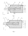
mechanical arm 7 shown inFig. 1 and Fig. 2 . As shown inFig. 1 and Fig. 2 , the ultrasonictherapeutic applicator 5 and some part of themechanical arm 7 are located in thebox 9 that containscouplant liquid 4. Themechanical arm 7 is seal-connected with thebox 9 through aflexible joining unit 8. During treatment, when themechanical arm 7 drives the focal point of ultrasonic therapeutic means to move within the target area, the level of couplant liquid in the box will vary accordingly. As shown inFig. 1 , when the ultrasonictherapeutic applicator 5 moves Δ X along the positive direction of X-axis, the level of couplant liquid in the box will change from H to H+Δ H1. As shown inFig. 2 , when the ultrasonictherapeutic applicator 5 moves ΔY along the positive direction of Y-axis, the level of couplant liquid in the box will change from H to H+Δ H2. - In the prior art, the flexible joining
unit 8 sometimes adopts flexible telescopic sleeve. If the shape of telescopic sleeve is selected appropriately, when the ultrasonic therapeutic applicator moves in Y-direction, Δ H2 = 0 and the liquid level keeps unchanged; but when the ultrasonic therapeutic applicator moves in X-direction and when Δ X ≠ 0, Δ H1 ≠ 0 and the liquid level varies. - When the imaging device is introduced into the ultrasonic therapeutic system, especially an MRI ( Magnetic Resonance Imaging ) apparatus, the level changes of couplant liquid will influence the imaging results of MRI and accordingly the diagnostic effect of MRI is influenced.
- Therefore, it is very important for an ultrasonic therapeutic system guided by MRI to keep the level of couplant liquid unchanged.
- Aiming at the disadvantages of ultrasonic therapeutic system in the prior art as mentioned above, the present invention is to provide an ultrasonic therapeutic means and an ultrasonic therapeutic system using the same, which can keep the level of couplant liquid stable when the ultrasonic therapeutic applicator moves. Thus, during treatment, the ultrasonic therapeutic system guided by an imaging device keeps the level of couplant liquid stable when the ultrasonic therapeutic applicator moves. Accordingly, the interference to imaging results of the imaging device due to changes of the liquid level can be reduced effectively, and the diagnostic accuracy of the imaging device and the therapeutic effects of the ultrasonic therapeutic means can be improved.
- The technical solution for the problems proposed by the present invention is as follows: the ultrasonic therapeutic means comprises an ultrasonic therapeutic applicator that includes an ultrasonic transducer, a box for containing the ultrasonic therapeutic applicator and couplant liquid, and a moving unit that drills through the wall of box and is connected to the ultrasonic therapeutic applicator. Wherein, compensating units, which will make the level of couplant liquid in the box unchanged when the moving unit drives the ultrasonic therapeutic applicator to move, are arranged on the box.
- Said compensating units can be arranged at both sides of the box and incorporate with the box. The moving unit drills through both of the compensating units and the ultrasonic therapeutic applicator is located between the two compensating units.
- Preferably, said compensating units can be two flexible telescopic sleeves with the same shape and size.
- During ultrasonic treatment, the compensating unit adopts flexible material so that it can move with the movement of moving unit when the ultrasonic transducer moves under the control of moving unit.
- Said moving unit may be a mechanical arm. The ultrasonic therapeutic applicator is located in the middle of the mechanical arm. Two flexible telescopic sleeves as compensating units are located at both sides of ultrasonic therapeutic applicator and are seal-connected with the mechanical arm.
- More preferably, said two flexible telescopic sleeves are symmetrically arranged at both sides of the box and the mechanical arm goes through the two flexible telescopic sleeves.
- The shape of the telescopic sleeve can be any shape that can compensate the liquid volume. In the present invention, in order to make an easy manufacture of the telescopic sleeve and to make use of its symmetrical arrangement more effectively, preferably the telescopic sleeve can be truncated-cone-shaped or prismoid-shaped.
- Said ultrasonic therapeutic applicator may be the ultrasonic transducer with a variable focal length or a fixed one. For an ultrasonic transducer with a variable focal length, its focal point may be changed by changing the driving signals or by controlling the moving unit or by both of them. For an ultrasonic transducer with a fixed focal length, its focal point can be changed only by controlling the moving unit. Therefore, the ultrasonic therapeutic applicator with an ultrasonic transducer having a fixed focal length is especially suitable to be used in the present invention.
- An ultrasonic therapeutic system of using the ultrasonic therapeutic means as mentioned above guided by an imaging device is available.
- In said ultrasonic therapeutic system guided by an imaging device, the imaging device can be B-mode scanner, CT, MRI and etc. When the B-mode scanner and CT are used to guide the ultrasonic therapeutic system for treatment, the changes on liquid level do not influence their imaging obviously; therefore, the present invention is especially applicable to MRI-guided ultrasonic therapeutic system.
- For the ultrasonic therapeutic system guided by an imaging device of the present invention, when the ultrasonic therapy applicator moves during treatment, the level of couplant liquid keeps stable due to the use of compensating units. Thus, the phenomenon of level changing of couplant liquid caused by the movement of the ultrasonic therapeutic applicator driven by moving unit in the prior art can be eliminated. A stable liquid level in the box can be ensured and accordingly the interference to imaging results of the imaging device due to liquid level changes can be reduced effectively and the diagnostic accuracy of the imaging device can be improved.
-
-
Fig. 1 is a structural diagram of an ultrasonic therapeutic means of prior art. It shows the level changes of couplant liquid when the moving unit drives the ultrasonic therapeutic applicator to move in X-direction. -
Fig. 2 is a structural diagram of an ultrasonic therapeutic means of prior art. It shows the level changes of couplant liquid when the moving unit drives the ultrasonic therapeutic applicator to move in Y-direction. -
Fig. 3 is a structural diagram of an ultrasonic therapeutic means of the present invention. -
Fig. 4 is a structural diagram of an ultrasonic therapeutic means of the present invention. It shows the level changes of couplant liquid when the moving unit drives the ultrasonic therapeutic applicator to move in X-direction. -
Fig. 5 is a structural diagram of an ultrasonic therapeutic means of the present invention. It shows the level changes of couplant liquid when the moving unit drives the ultrasonic therapeutic applicator to move in Y-direction. -
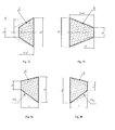
Fig. 6a is a front view of the structure of the truncated-cone-shaped telescopic sleeve under the initial status of the ultrasonic therapeutic means in theembodiment 1 of the present invention. -
Fig. 6b is a side view ofFig. 6a . -
Fig. 7a shows the shape changes of the first compensatingunit 2 when themechanical arm 1 moves in X-direction in theembodiment 1 of the present invention. -
Fig. 7b shows the shape changes of the second compensatingunit 6 when themechanical arm 1 moves in X-direction in theembodiment 1 of the present invention. -
Fig. 8a shows the shape changes of the first compensatingunit 2 when themechanical arm 1 moves in Y-direction in theembodiment 1 of the present invention. -
Fig. 8b shows the shape changes of the second compensatingunit 6 when themechanical arm 1 moves in Y-direction in theembodiment 1 of the present invention. -
Fig. 9a is a front view of the structure of the prismoid-shaped telescopic sleeve under the initial status of the ultrasonic therapeutic means in theembodiment 2 of the present invention. -
Fig. 9b is a side view ofFig. 9a . -
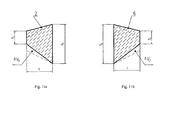
Fig. 10a shows the shape changes of the first compensatingunit 2 when themechanical arm 1 moves in X-direction in theembodiment 2 of the present invention. -
Fig. 10b shows the shape changes of the second compensatingunit 6 when themechanical arm 1 moves in X-direction in theembodiment 2 of the present invention. -
Fig. 11 a shows the shape changes of the first compensatingunit 2 when themechanical arm 1 moves in Y-direction in theembodiment 2 of the present invention. -
Fig. 11b shows the shape changes of the second compensatingunit 6 when themechanical arm 1 moves in Y-direction in theembodiment 2 of the present invention. - Wherein:
- Broken lines indicate the original position of the subject before it moves.
- 1, 7 - Mechanical arm 2 -
First compensating unit 3, 9 - Box 4 - Couplant liquid 5 - Ultrasonic therapeutic applicator 6 - Second compensating unit 8 - Flexible joining unit - The present invention will be further explained below in detail with reference to the preferred embodiments and accompanying drawings.
- As shown in
Fig. 3, Fig. 4 andFig. 5 , the ultrasonic therapeutic system guided by an imaging device consists of an imaging device for imaging the target (not illustrated in figures) and an ultrasonic therapeutic means. Said ultrasonic therapeutic means comprises an ultrasonictherapeutic applicator 5 that includes an ultrasonic transducer, abox 3, and a moving unit that is connected to the ultrasonictherapeutic applicator 5 and controls its movement, i.e.mechanical arm 1. - The ultrasonic
therapeutic applicator 5 is placed in thebox 3 that is full of couplant liquid. Themechanical arm 1 that drives ultrasonictherapeutic applicator 5 to move, drills through the wall of the box and is connected to the ultrasonictherapeutic applicator 5. The compensating units are arranged on thebox 3 and make the level of couplant liquid in thebox 3 unchanged when themechanical arm 7 drives the ultrasonictherapeutic applicator 5 to move. - Said compensating units are the first compensating
unit 2 and the second compensatingunit 6, which are arranged symmetrically at both sides of thebox 3 and incorporate with thebox 3. The two symmetrical compensating units have the same shape and size. Themechanical arm 1 drills horizontally through the two symmetrical compensating units; the ultrasonictherapeutic applicator 5 on themechanical arm 1 is located between the two compensating units. The two compensating units are sealed and fixed with themechanical arm 1 at one end and are sealed and fixed with thebox 3 at the other end. The compensating units adopt flexible telescopic sleeves, which are made from flexible material. At the connection points of two flexible telescopic sleeves, themechanical arm 1 has a suitable shape corresponding to the connection ends of flexible telescopic sleeves. Two flexible telescopic sleeves have certain capability of repeated deformation when driven by themechanical arm 1. For example, when the mechanical arm I moves in X-direction, two flexible telescopic sleeves correspondingly elongate or shorten the same length in X-direction; when themechanical arm 1 moves in Y-direction and Z-direction, two flexible telescopic sleeves deform correspondingly. - During treatment, the
mechanical arm 1 drives the ultrasonictherapeutic applicator 5 to move and accordingly its focal point moves. The ultrasonic waves transmitted from the ultrasonictherapeutic applicator 5 go through thecouplant liquid 4 and then are focused at the target (not illustrated in figures.). The focal point of the ultrasonictherapeutic applicator 5 can move in X, Y, Z-directions to meet the requirements for the three-dimensional entity of the target to be treated. The compensating units move when themechanical arm 1 moves and can deform in X, Y, Z-directions. - When the focal point of the ultrasonic transducer is required to move in X-direction, the
mechanical arm 1 drives the ultrasonictherapeutic applicator 5 to move in X-direction. As shown inFig. 4 , when themechanical arm 1 moves Δ X toward +X-direction, it drives the ultrasonictherapeutic applicator 5 to move Δ X and meanwhile the first compensatingunit 2 shortens Δ X and the second compensatingunit 6 elongates Δ X. The volume change in the first compensatingunit 2 is Δ V1 and the volume change in the second compensatingunit 6 is Δ V2. A certain structural shape for the first compensatingunit 2 and the second compensatingunit 6 can be selected so that the formula Δ V1 + Δ V2=0 becomes possible. Therefore, when the ultrasonictherapeutic applicator 5 moves in X-direction, the sum of volumes of thebox 3 and the two compensating units is not changed and accordingly the level of couplant liquid in the box keeps unchanged before and after the mechanical arm moves. - When the focal point of the ultrasonic transducer is required to move in Y-direction, the
mechanical arm 1 drives the ultrasonictherapeutic applicator 5 to move in Y-direction. As shown inFig. 5 , when themechanical arm 1 moves Δ Y toward +Y-direction, it drives the ultrasonictherapeutic applicator 5 to move Δ Y and meanwhile the first compensatingunit 2 and the second compensatingunit 6 move Δ Y in Y-direction. The volume change in the first compensatingunit 2 is Δ V1 and the volume change in the second compensatingunit 6 is Δ V2. A certain structural shape for the first compensatingunit 2 and the second compensatingunit 6 can be selected so that the formula Δ V1 + Δ V2=0 becomes possible. Therefore, when the ultrasonictherapeutic applicator 5 moves in Y-direction, the sum of volumes of thebox 3 and the two compensating units is not changed and accordingly the level of couplant liquid in the box keeps unchanged before and after the mechanical arm moves. - When the focal point of the ultrasonic transducer is required to move in Z-direction, the conditions of movement can be analyzed with reference to the movement in Y-direction and it will not be repeated here.
- In the following two embodiments, only the shape changes of the compensating units are described and other structures are the same as mentioned above. Here the MRI apparatus is selected as the imaging device and the ultrasonic transducer in the ultrasonic
therapeutic applicator 5 adopts an ultrasonic transducer with a fixed focal length. - As shown in
Fig. 6a and Fig. 6b , in this embodiment, both the first compensatingunit 2 and the second compensatingunit 6 adopt truncated-cone-shaped flexible telescopic sleeves. The area of the upper surface of truncated-cone ( small end "a" ) is S1 and the area of the lower surface of truncated-cone ( big end "b") is S2. The length of the truncated-cone is T when the ultrasonictherapeutic applicator 5 is in static status. The small end "a" is fixed with and connected to themechanical arm 1 and the big end "b" is fixed with and connected to thebox 3. - Under the control of the
mechanical arm 1, when the focal point of the ultrasonictherapeutic applicator 5 moves in X-direction ( as shown inFig. 4 ), as shown inFig. 7a and Fig. 7b , V=volume of telescopic sleeve, from geometry we know:
- When the ultrasonic
therapeutic applicator 5 moves towards X-direction, S1 is not changed during movement because the small end "a" of the truncated-cone-shaped compensating unit is fixed with themechanical arm 1 and meanwhile S2 is also not changed because the big end "b" of the truncated-cone-shaped compensating unit is fixed with thebox 3. -
Fig. 7a shows the shape changes of the first compensatingunit 2 as below:
-
Fig. 7b shows the shape changes of the second compensatingunit 6 as below:

- Therefore, when moving in X-direction, the total volume change of the two compensating units is zero and the level of couplant liquid keeps stable.
- When the focal point of the ultrasonic therapeutic means in
Fig. 3 moves towards Y-direction, under the control of themechanical arm 1, the focal point of the ultrasonictherapeutic applicator 5 moves towards Y-direction ( as shown inFig. 5 ). The volume change of the first compensatingunit 2 is shown inFig. 8a :
- The volume change of the
second compensation unit 6 is shown inFig. 8b :

- Therefore, when moving in Y-direction, the total volume change of the two compensation units is zero and the level of couplant liquid keeps stable.
- The conditions of movement when the ultrasonic therapeutic means moves towards Z-direction are the same as when moving towards Y-direction and it will not be repeated here.
- From this, it can be seen that in this embodiment, the level of couplant liquid can keep stable surely when the ultrasonic
therapeutic applicator 5 moves in X, Y and Z-directions and when themechanical arm 1 drives the focal point of the ultrasonic therapeutic applicator to move. - As shown in
Fig. 9a and Fig. 9b , in this embodiment, the first compensatingunit 2 and the second compensatingunit 6 are prismoid-shaped flexible telescopic sleeves. The length and width of its upper surface is B1 and A1, and its area is S1. The length and width of its lower surface is B2 and A2, and its area is S2. The height of the prismoid is T. The other structures are the same as those inembodiment 1. - Volume of prismoid:

- When the ultrasonic
therapeutic applicator 5 inFig. 4 moves towards X-direction, as shown inFig. 10a , the height of the first compensatingunit 2 is changed from T to T - Δ T, butS 1 and S2 are not changed during movement. The volume change of the first compensatingunit 2 after movement is as below:
- As shown in
Fig. 10b , the height of the second compensatingunit 6 is changed from T to T+ΔT, butS 1 and S2 are not changed during movement. The volume change of the second compensatingunit 6 after movement is as below:

- Therefore, when moving in X-direction, the total volume change of the two compensating units is zero and the level of couplant liquid keeps stable.
- When the focal point of the ultrasonic
therapeutic applicator 5 inFig. 5 moves towards Y-direction, the volume change of the first compensatingunit 2 is shown inFig. 11a :
- The volume change of the second compensating
unit 6 is shown inFig. 11b :

- Therefore, when moving in Y-direction, the total volume change of the two compensating units is zero and the level of couplant liquid keeps stable.
- From this, we can conclude that the sum of volumes of the two compensating units before and after movement keeps unchanged and the level of couplant liquid will keep the original level.
- The conditions of movement when the ultrasonic therapeutic means moving towards Z-direction are the same as when moving towards Y-direction and it will not be repeated here.
- From the
embodiment 1 andembodiment 2, it can be seen that two flexible telescopic sleeves arranged symmetrically at both sides of thebox 3 and sealed and fixed with themechanical arm 1 are provided here, so that the level of couplant liquid can keep stable surely when themechanical arm 1 moves in X, Y and Z-directions, and accordingly the interference to MRI can be minimized to the utmost and the diagnostic accuracy of MRI apparatus is improved.
Claims (8)
- An ultrasonic therapeutic means comprises an ultrasonic therapeutic applicator (5) that includes an ultrasonic transducer, a box (3) for containing the ultrasonic therapeutic applicator and couplant liquid, and a moving unit for the ultrasonic therapeutic applicator that drills through the wall of the box and is connected to the ultrasonic therapeutic applicator; wherein the ultrasonic therapeutic means further comprises two compensating units (2, 6) arranged at both sides of the box and incorporating with the box (3); wherein the moving unit drills through both of the two compensating units (2, 6) and the ultrasonic therapeutic applicator (5) is located between the two compensating units; and wherein said compensating units (2, 6) are shaped to make the total volume change of the two compensating units be zero when the moving unit drives the ultrasonic therapeutic applicator to move.
- The ultrasonic therapeutic means of claim 1, wherein said compensating units (2, 6) are two flexible telescopic sleeves; and wherein the moving unit drills through the two flexible telescopic sleeves and is seal-connected with the two flexible telescopic sleeves.
- The ultrasonic therapeutic means of claim 2, wherein said two flexible telescopic sleeves have the same shape and size.
- The ultrasonic therapeutic means of claim 3, wherein said moving unit is mechanical arm (1), and the ultrasonic therapeutic applicator (5) is located in the middle of the mechanical arm (1); two flexible telescopic sleeves as compensating units are located at both sides of the ultrasonic therapeutic applicator (5) and are seal-connected with the mechanical arm (1).
- The ultrasonic therapeutic means of claim 4, wherein said two flexible telescopic sleeves are arranged at both sides of the box symmetrically and the mechanical arm (1) goes through the two flexible telescopic sleeves.
- The ultrasonic therapeutic means of claim 5, wherein said two flexible telescopic sleeves as compensating units are truncated-cone-shaped or prismoid-shaped.
- An ultrasonic therapeutic system guided by an imaging device, comprising an imaging device and an ultrasonic therapeutic means, wherein said ultrasonic therapeutic means is the ultrasonic therapeutic means as claimed in any one of claims 1-6.
- The ultrasonic therapeutic system guided by an imaging device of claim 7, wherein said imaging device is an MRI apparatus.
Applications Claiming Priority (2)
| Application Number | Priority Date | Filing Date | Title |
|---|---|---|---|
| CN200610111925A CN100574828C (en) | 2006-08-24 | 2006-08-24 | An ultrasonic treatment device and an ultrasonic treatment system containing the ultrasonic treatment device |
| PCT/CN2007/000544 WO2008025191A1 (en) | 2006-08-24 | 2007-02-14 | An ultasonic therapeutic means and an ultrasonic therapeutic system of using the same |
Publications (3)
| Publication Number | Publication Date |
|---|---|
| EP2058029A1 EP2058029A1 (en) | 2009-05-13 |
| EP2058029A4 EP2058029A4 (en) | 2010-09-29 |
| EP2058029B1 true EP2058029B1 (en) | 2011-08-31 |
Family
ID=39127627
Family Applications (1)
| Application Number | Title | Priority Date | Filing Date |
|---|---|---|---|
| EP07710965A Not-in-force EP2058029B1 (en) | 2006-08-24 | 2007-02-14 | Ultrasonic therapeutic means and ultrasonic therapeutic system using the same |
Country Status (9)
| Country | Link |
|---|---|
| US (1) | US8057409B2 (en) |
| EP (1) | EP2058029B1 (en) |
| JP (1) | JP4991858B2 (en) |
| CN (1) | CN100574828C (en) |
| AT (1) | ATE522248T1 (en) |
| CA (1) | CA2660233A1 (en) |
| ES (1) | ES2370045T3 (en) |
| RU (1) | RU2426568C2 (en) |
| WO (1) | WO2008025191A1 (en) |
Families Citing this family (5)
| Publication number | Priority date | Publication date | Assignee | Title |
|---|---|---|---|---|
| CN100574829C (en) * | 2006-08-24 | 2009-12-30 | 重庆融海超声医学工程研究中心有限公司 | A high-intensity focused ultrasound treatment system guided by imaging equipment |
| AU2012326218B2 (en) | 2011-10-17 | 2017-03-09 | Butterfly Network, Inc. | Transmissive imaging and related apparatus and methods |
| US9667889B2 (en) | 2013-04-03 | 2017-05-30 | Butterfly Network, Inc. | Portable electronic devices with integrated imaging capabilities |
| CN109381807A (en) * | 2017-08-14 | 2019-02-26 | 重庆海扶医疗科技股份有限公司 | Ultrasound monitoring system and method, ultrasound treatment system |
| CN118750808B (en) * | 2024-07-02 | 2024-11-29 | 南京华伟医疗设备有限公司 | Ultrasonic therapeutic apparatus |
Family Cites Families (13)
| Publication number | Priority date | Publication date | Assignee | Title |
|---|---|---|---|---|
| AU1165483A (en) * | 1982-02-26 | 1983-09-01 | Technicare Corp. | Ultrasound fluid chamber volume control |
| US4517840A (en) * | 1982-10-18 | 1985-05-21 | General Electric Company | Ultrasonic sector scanner having fluid replacement capability |
| WO1993016641A1 (en) * | 1992-02-21 | 1993-09-02 | Diasonics, Inc. | Ultrasound intracavity system for imaging therapy planning and treatment of focal disease |
| DE19745400C1 (en) * | 1997-10-14 | 1999-04-15 | Siemens Ag | Ultrasonic breast tumour therapy process |
| CN1058905C (en) * | 1998-01-25 | 2000-11-29 | 重庆海扶(Hifu)技术有限公司 | High-intensity focusing ultrasonic tumor scanning treatment system |
| DE19935724A1 (en) * | 1999-07-29 | 2001-02-15 | Wolf Gmbh Richard | Therapy devices for shock wave treatment of a patient |
| US6626855B1 (en) * | 1999-11-26 | 2003-09-30 | Therus Corpoation | Controlled high efficiency lesion formation using high intensity ultrasound |
| SE518763C2 (en) * | 2000-07-17 | 2002-11-19 | Ultrazonix Dnt Ab | Device for non-invasive ultrasound treatment of disk disease |
| US20030171701A1 (en) * | 2002-03-06 | 2003-09-11 | Eilaz Babaev | Ultrasonic method and device for lypolytic therapy |
| JP2003309890A (en) * | 2002-04-17 | 2003-10-31 | Matsushita Electric Ind Co Ltd | Ultrasonic probe |
| JP3777348B2 (en) * | 2002-10-24 | 2006-05-24 | 松下電器産業株式会社 | Ultrasonic probe |
| CN100479890C (en) * | 2005-01-31 | 2009-04-22 | 重庆海扶(Hifu)技术有限公司 | Permeable Membrane Coupling Devices for High Intensity Focused Ultrasound Therapy |
| CN100484592C (en) * | 2005-09-26 | 2009-05-06 | 西安交通大学 | High-strength focus supersonic therapeutic system of hundred array-element composite material and controlling array by spherical-phase |
-
2006
- 2006-08-24 CN CN200610111925A patent/CN100574828C/en not_active Expired - Fee Related
-
2007
- 2007-02-14 US US12/376,472 patent/US8057409B2/en not_active Expired - Fee Related
- 2007-02-14 WO PCT/CN2007/000544 patent/WO2008025191A1/en not_active Ceased
- 2007-02-14 AT AT07710965T patent/ATE522248T1/en not_active IP Right Cessation
- 2007-02-14 EP EP07710965A patent/EP2058029B1/en not_active Not-in-force
- 2007-02-14 ES ES07710965T patent/ES2370045T3/en active Active
- 2007-02-14 JP JP2009524867A patent/JP4991858B2/en not_active Expired - Fee Related
- 2007-02-14 CA CA002660233A patent/CA2660233A1/en not_active Abandoned
- 2007-02-14 RU RU2009102487/14A patent/RU2426568C2/en not_active IP Right Cessation
Also Published As
| Publication number | Publication date |
|---|---|
| ES2370045T3 (en) | 2011-12-12 |
| ATE522248T1 (en) | 2011-09-15 |
| JP4991858B2 (en) | 2012-08-01 |
| CN101130125A (en) | 2008-02-27 |
| EP2058029A4 (en) | 2010-09-29 |
| US20100234773A1 (en) | 2010-09-16 |
| JP2010501215A (en) | 2010-01-21 |
| US8057409B2 (en) | 2011-11-15 |
| RU2009102487A (en) | 2010-09-27 |
| CA2660233A1 (en) | 2008-03-06 |
| CN100574828C (en) | 2009-12-30 |
| WO2008025191A1 (en) | 2008-03-06 |
| EP2058029A1 (en) | 2009-05-13 |
| RU2426568C2 (en) | 2011-08-20 |
Similar Documents
| Publication | Publication Date | Title |
|---|---|---|
| Dohrmann et al. | Intraoperative ultrasound imaging of the spinal cord: syringomyelia, cysts, and tumors—a preliminary report | |
| EP3446635B1 (en) | Ultrasonic probe and ultrasonic detection device provided with said ultrasonic probe | |
| US8224420B2 (en) | MRI guided ultrasound therapy apparatus | |
| JP4713339B2 (en) | High frequency high frame rate ultrasound imaging system | |
| DE69832425T2 (en) | System for performing surgery, biopsy, ablation of a tumor or other physical abnormality | |
| US20060241459A1 (en) | Automatic signal-optimizing transducer assembly for blood flow measurement | |
| US20190159753A1 (en) | Motor-Assisted Needle Guide Assembly for Ultrasound Needle Placement | |
| EP2058029A1 (en) | An ultrasonic therapeutic means and an ultrasonic therapeutic system of using the same | |
| JPS6346147A (en) | Ultrasonic remedy apparatus | |
| US20190388062A1 (en) | Apparatus, System, and Method for Increasing Object Visibility | |
| EP2979644B1 (en) | Ultrasonic probe for puncture needle and ultrasonic diagnostic device using same | |
| He et al. | 3-D high frequency ultrasound imaging by piezo-driving a single-element transducer | |
| WO2008020157A1 (en) | Ultrasonic imaging of an elongate device penetrating an object | |
| CN113893036A (en) | An interventional robotic device in a magnetic resonance environment | |
| WO2007082495A1 (en) | Mri positioning system for ultrasound brain surgery | |
| JP7716133B1 (en) | Acoustic coupler for HIFU treatment | |
| JP7301426B1 (en) | HIFU irradiation equipment | |
| JP7503342B1 (en) | HIFU irradiation device and method for evaluating its condition | |
| JPH02277448A (en) | Shock wave treatment apparatus | |
| EP4226874A1 (en) | Ultrasound and/or shock wave device with hexapod platform mounted source | |
| JP4778385B2 (en) | Pressurization mechanism and ultrasonic diagnostic apparatus | |
| WO2026018529A1 (en) | Hifu irradiation device | |
| CN121910400A (en) | Novel transesophageal ultrasonic biplane probe and operation vision imaging navigation system thereof | |
| CN121001659A (en) | Ultrasonic probe vibration system, method, and apparatus for medical imaging of elasticity and viscoelasticity. | |
| JPH0386156A (en) | Body cavity sticking probe |
Legal Events
| Date | Code | Title | Description |
|---|---|---|---|
| PUAI | Public reference made under article 153(3) epc to a published international application that has entered the european phase |
Free format text: ORIGINAL CODE: 0009012 |
|
| 17P | Request for examination filed |
Effective date: 20090319 |
|
| AK | Designated contracting states |
Kind code of ref document: A1 Designated state(s): AT BE BG CH CY CZ DE DK EE ES FI FR GB GR HU IE IS IT LI LT LU LV MC NL PL PT RO SE SI SK TR |
|
| AX | Request for extension of the european patent |
Extension state: AL BA HR MK RS |
|
| A4 | Supplementary search report drawn up and despatched |
Effective date: 20100831 |
|
| RIC1 | Information provided on ipc code assigned before grant |
Ipc: A61N 7/02 20060101ALI20100825BHEP Ipc: A61N 7/00 20060101AFI20080407BHEP Ipc: G06F 9/48 20060101ALI20100825BHEP Ipc: G10K 11/35 20060101ALI20100825BHEP |
|
| GRAP | Despatch of communication of intention to grant a patent |
Free format text: ORIGINAL CODE: EPIDOSNIGR1 |
|
| RIC1 | Information provided on ipc code assigned before grant |
Ipc: A61N 7/02 20060101ALI20110330BHEP Ipc: G10K 11/35 20060101ALI20110330BHEP Ipc: A61N 7/00 20060101AFI20110330BHEP Ipc: G06F 9/48 20060101ALI20110330BHEP |
|
| RTI1 | Title (correction) |
Free format text: ULTRASONIC THERAPEUTIC MEANS AND ULTRASONIC THERAPEUTIC SYSTEM USING THE SAME |
|
| GRAS | Grant fee paid |
Free format text: ORIGINAL CODE: EPIDOSNIGR3 |
|
| GRAA | (expected) grant |
Free format text: ORIGINAL CODE: 0009210 |
|
| DAX | Request for extension of the european patent (deleted) | ||
| AK | Designated contracting states |
Kind code of ref document: B1 Designated state(s): AT BE BG CH CY CZ DE DK EE ES FI FR GB GR HU IE IS IT LI LT LU LV MC NL PL PT RO SE SI SK TR |
|
| REG | Reference to a national code |
Ref country code: GB Ref legal event code: FG4D Ref country code: CH Ref legal event code: EP |
|
| REG | Reference to a national code |
Ref country code: IE Ref legal event code: FG4D |
|
| REG | Reference to a national code |
Ref country code: DE Ref legal event code: R096 Ref document number: 602007016760 Country of ref document: DE Effective date: 20111103 |
|
| REG | Reference to a national code |
Ref country code: ES Ref legal event code: FG2A Ref document number: 2370045 Country of ref document: ES Kind code of ref document: T3 Effective date: 20111212 |
|
| REG | Reference to a national code |
Ref country code: NL Ref legal event code: VDEP Effective date: 20110831 |
|
| LTIE | Lt: invalidation of european patent or patent extension |
Effective date: 20110831 |
|
| PG25 | Lapsed in a contracting state [announced via postgrant information from national office to epo] |
Ref country code: LT Free format text: LAPSE BECAUSE OF FAILURE TO SUBMIT A TRANSLATION OF THE DESCRIPTION OR TO PAY THE FEE WITHIN THE PRESCRIBED TIME-LIMIT Effective date: 20110831 Ref country code: SE Free format text: LAPSE BECAUSE OF FAILURE TO SUBMIT A TRANSLATION OF THE DESCRIPTION OR TO PAY THE FEE WITHIN THE PRESCRIBED TIME-LIMIT Effective date: 20110831 Ref country code: FI Free format text: LAPSE BECAUSE OF FAILURE TO SUBMIT A TRANSLATION OF THE DESCRIPTION OR TO PAY THE FEE WITHIN THE PRESCRIBED TIME-LIMIT Effective date: 20110831 Ref country code: NL Free format text: LAPSE BECAUSE OF FAILURE TO SUBMIT A TRANSLATION OF THE DESCRIPTION OR TO PAY THE FEE WITHIN THE PRESCRIBED TIME-LIMIT Effective date: 20110831 Ref country code: IS Free format text: LAPSE BECAUSE OF FAILURE TO SUBMIT A TRANSLATION OF THE DESCRIPTION OR TO PAY THE FEE WITHIN THE PRESCRIBED TIME-LIMIT Effective date: 20111231 |
|
| REG | Reference to a national code |
Ref country code: AT Ref legal event code: MK05 Ref document number: 522248 Country of ref document: AT Kind code of ref document: T Effective date: 20110831 |
|
| PG25 | Lapsed in a contracting state [announced via postgrant information from national office to epo] |
Ref country code: SI Free format text: LAPSE BECAUSE OF FAILURE TO SUBMIT A TRANSLATION OF THE DESCRIPTION OR TO PAY THE FEE WITHIN THE PRESCRIBED TIME-LIMIT Effective date: 20110831 Ref country code: GR Free format text: LAPSE BECAUSE OF FAILURE TO SUBMIT A TRANSLATION OF THE DESCRIPTION OR TO PAY THE FEE WITHIN THE PRESCRIBED TIME-LIMIT Effective date: 20111201 Ref country code: CY Free format text: LAPSE BECAUSE OF FAILURE TO SUBMIT A TRANSLATION OF THE DESCRIPTION OR TO PAY THE FEE WITHIN THE PRESCRIBED TIME-LIMIT Effective date: 20110831 Ref country code: AT Free format text: LAPSE BECAUSE OF FAILURE TO SUBMIT A TRANSLATION OF THE DESCRIPTION OR TO PAY THE FEE WITHIN THE PRESCRIBED TIME-LIMIT Effective date: 20110831 Ref country code: LV Free format text: LAPSE BECAUSE OF FAILURE TO SUBMIT A TRANSLATION OF THE DESCRIPTION OR TO PAY THE FEE WITHIN THE PRESCRIBED TIME-LIMIT Effective date: 20110831 |
|
| PG25 | Lapsed in a contracting state [announced via postgrant information from national office to epo] |
Ref country code: BE Free format text: LAPSE BECAUSE OF FAILURE TO SUBMIT A TRANSLATION OF THE DESCRIPTION OR TO PAY THE FEE WITHIN THE PRESCRIBED TIME-LIMIT Effective date: 20110831 |
|
| PG25 | Lapsed in a contracting state [announced via postgrant information from national office to epo] |
Ref country code: CZ Free format text: LAPSE BECAUSE OF FAILURE TO SUBMIT A TRANSLATION OF THE DESCRIPTION OR TO PAY THE FEE WITHIN THE PRESCRIBED TIME-LIMIT Effective date: 20110831 Ref country code: SK Free format text: LAPSE BECAUSE OF FAILURE TO SUBMIT A TRANSLATION OF THE DESCRIPTION OR TO PAY THE FEE WITHIN THE PRESCRIBED TIME-LIMIT Effective date: 20110831 |
|
| PG25 | Lapsed in a contracting state [announced via postgrant information from national office to epo] |
Ref country code: RO Free format text: LAPSE BECAUSE OF FAILURE TO SUBMIT A TRANSLATION OF THE DESCRIPTION OR TO PAY THE FEE WITHIN THE PRESCRIBED TIME-LIMIT Effective date: 20110831 Ref country code: PL Free format text: LAPSE BECAUSE OF FAILURE TO SUBMIT A TRANSLATION OF THE DESCRIPTION OR TO PAY THE FEE WITHIN THE PRESCRIBED TIME-LIMIT Effective date: 20110831 Ref country code: PT Free format text: LAPSE BECAUSE OF FAILURE TO SUBMIT A TRANSLATION OF THE DESCRIPTION OR TO PAY THE FEE WITHIN THE PRESCRIBED TIME-LIMIT Effective date: 20120102 Ref country code: EE Free format text: LAPSE BECAUSE OF FAILURE TO SUBMIT A TRANSLATION OF THE DESCRIPTION OR TO PAY THE FEE WITHIN THE PRESCRIBED TIME-LIMIT Effective date: 20110831 |
|
| PG25 | Lapsed in a contracting state [announced via postgrant information from national office to epo] |
Ref country code: DK Free format text: LAPSE BECAUSE OF FAILURE TO SUBMIT A TRANSLATION OF THE DESCRIPTION OR TO PAY THE FEE WITHIN THE PRESCRIBED TIME-LIMIT Effective date: 20110831 |
|
| PLBE | No opposition filed within time limit |
Free format text: ORIGINAL CODE: 0009261 |
|
| STAA | Information on the status of an ep patent application or granted ep patent |
Free format text: STATUS: NO OPPOSITION FILED WITHIN TIME LIMIT |
|
| 26N | No opposition filed |
Effective date: 20120601 |
|
| REG | Reference to a national code |
Ref country code: DE Ref legal event code: R097 Ref document number: 602007016760 Country of ref document: DE Effective date: 20120601 |
|
| PG25 | Lapsed in a contracting state [announced via postgrant information from national office to epo] |
Ref country code: MC Free format text: LAPSE BECAUSE OF NON-PAYMENT OF DUE FEES Effective date: 20120229 |
|
| REG | Reference to a national code |
Ref country code: CH Ref legal event code: PL |
|
| PG25 | Lapsed in a contracting state [announced via postgrant information from national office to epo] |
Ref country code: LI Free format text: LAPSE BECAUSE OF NON-PAYMENT OF DUE FEES Effective date: 20120229 Ref country code: CH Free format text: LAPSE BECAUSE OF NON-PAYMENT OF DUE FEES Effective date: 20120229 |
|
| REG | Reference to a national code |
Ref country code: IE Ref legal event code: MM4A |
|
| PG25 | Lapsed in a contracting state [announced via postgrant information from national office to epo] |
Ref country code: IE Free format text: LAPSE BECAUSE OF NON-PAYMENT OF DUE FEES Effective date: 20120214 |
|
| PG25 | Lapsed in a contracting state [announced via postgrant information from national office to epo] |
Ref country code: BG Free format text: LAPSE BECAUSE OF FAILURE TO SUBMIT A TRANSLATION OF THE DESCRIPTION OR TO PAY THE FEE WITHIN THE PRESCRIBED TIME-LIMIT Effective date: 20111130 |
|
| PG25 | Lapsed in a contracting state [announced via postgrant information from national office to epo] |
Ref country code: TR Free format text: LAPSE BECAUSE OF FAILURE TO SUBMIT A TRANSLATION OF THE DESCRIPTION OR TO PAY THE FEE WITHIN THE PRESCRIBED TIME-LIMIT Effective date: 20110831 |
|
| PG25 | Lapsed in a contracting state [announced via postgrant information from national office to epo] |
Ref country code: LU Free format text: LAPSE BECAUSE OF NON-PAYMENT OF DUE FEES Effective date: 20120214 |
|
| PG25 | Lapsed in a contracting state [announced via postgrant information from national office to epo] |
Ref country code: HU Free format text: LAPSE BECAUSE OF FAILURE TO SUBMIT A TRANSLATION OF THE DESCRIPTION OR TO PAY THE FEE WITHIN THE PRESCRIBED TIME-LIMIT Effective date: 20070214 |
|
| REG | Reference to a national code |
Ref country code: FR Ref legal event code: PLFP Year of fee payment: 10 |
|
| REG | Reference to a national code |
Ref country code: FR Ref legal event code: PLFP Year of fee payment: 11 |
|
| REG | Reference to a national code |
Ref country code: FR Ref legal event code: PLFP Year of fee payment: 12 |
|
| PGFP | Annual fee paid to national office [announced via postgrant information from national office to epo] |
Ref country code: FI Payment date: 20190211 Year of fee payment: 15 |
|
| PG25 | Lapsed in a contracting state [announced via postgrant information from national office to epo] |
Ref country code: IT Free format text: LAPSE BECAUSE OF NON-PAYMENT OF DUE FEES Effective date: 20200214 |
|
| P01 | Opt-out of the competence of the unified patent court (upc) registered |
Effective date: 20230526 |
|
| PGFP | Annual fee paid to national office [announced via postgrant information from national office to epo] |
Ref country code: ES Payment date: 20240321 Year of fee payment: 18 |
|
| PGFP | Annual fee paid to national office [announced via postgrant information from national office to epo] |
Ref country code: DE Payment date: 20240220 Year of fee payment: 18 Ref country code: GB Payment date: 20240220 Year of fee payment: 18 |
|
| PGFP | Annual fee paid to national office [announced via postgrant information from national office to epo] |
Ref country code: FR Payment date: 20240220 Year of fee payment: 18 |
|
| REG | Reference to a national code |
Ref country code: DE Ref legal event code: R119 Ref document number: 602007016760 Country of ref document: DE |
|
| GBPC | Gb: european patent ceased through non-payment of renewal fee |
Effective date: 20250214 |
|
| PG25 | Lapsed in a contracting state [announced via postgrant information from national office to epo] |
Ref country code: DE Free format text: LAPSE BECAUSE OF NON-PAYMENT OF DUE FEES Effective date: 20250902 |
|
| PG25 | Lapsed in a contracting state [announced via postgrant information from national office to epo] |
Ref country code: GB Free format text: LAPSE BECAUSE OF NON-PAYMENT OF DUE FEES Effective date: 20250214 |
|
| PG25 | Lapsed in a contracting state [announced via postgrant information from national office to epo] |
Ref country code: FR Free format text: LAPSE BECAUSE OF NON-PAYMENT OF DUE FEES Effective date: 20250228 |
|
| REG | Reference to a national code |
Ref country code: ES Ref legal event code: FD2A Effective date: 20260330 |
|
| PG25 | Lapsed in a contracting state [announced via postgrant information from national office to epo] |
Ref country code: ES Free format text: LAPSE BECAUSE OF NON-PAYMENT OF DUE FEES Effective date: 20250215 |