EP2057588B1 - Security peripheral integrated with a contactless object of secure document type with radiofrequency device - Google Patents
Security peripheral integrated with a contactless object of secure document type with radiofrequency device Download PDFInfo
- Publication number
- EP2057588B1 EP2057588B1 EP07823411A EP07823411A EP2057588B1 EP 2057588 B1 EP2057588 B1 EP 2057588B1 EP 07823411 A EP07823411 A EP 07823411A EP 07823411 A EP07823411 A EP 07823411A EP 2057588 B1 EP2057588 B1 EP 2057588B1
- Authority
- EP
- European Patent Office
- Prior art keywords
- chip
- reader
- antenna
- main
- portable object
- Prior art date
- Legal status (The legal status is an assumption and is not a legal conclusion. Google has not performed a legal analysis and makes no representation as to the accuracy of the status listed.)
- Revoked
Links
- 230000002093 peripheral effect Effects 0.000 title 1
- 238000004891 communication Methods 0.000 claims abstract description 8
- 238000001514 detection method Methods 0.000 claims description 14
- 230000000873 masking effect Effects 0.000 claims description 8
- 230000005540 biological transmission Effects 0.000 claims description 6
- 229910052751 metal Inorganic materials 0.000 claims description 3
- 239000002184 metal Substances 0.000 claims description 3
- 230000006870 function Effects 0.000 description 14
- 230000008878 coupling Effects 0.000 description 8
- 238000010168 coupling process Methods 0.000 description 8
- 238000005859 coupling reaction Methods 0.000 description 8
- 230000005672 electromagnetic field Effects 0.000 description 8
- 230000009849 deactivation Effects 0.000 description 3
- 230000002747 voluntary effect Effects 0.000 description 3
- 239000003990 capacitor Substances 0.000 description 2
- 239000000470 constituent Substances 0.000 description 2
- 239000000203 mixture Substances 0.000 description 2
- 229910001316 Ag alloy Inorganic materials 0.000 description 1
- RYGMFSIKBFXOCR-UHFFFAOYSA-N Copper Chemical compound [Cu] RYGMFSIKBFXOCR-UHFFFAOYSA-N 0.000 description 1
- 229910052782 aluminium Inorganic materials 0.000 description 1
- XAGFODPZIPBFFR-UHFFFAOYSA-N aluminium Chemical compound [Al] XAGFODPZIPBFFR-UHFFFAOYSA-N 0.000 description 1
- 238000013475 authorization Methods 0.000 description 1
- 229910052802 copper Inorganic materials 0.000 description 1
- 239000010949 copper Substances 0.000 description 1
- 230000001419 dependent effect Effects 0.000 description 1
- 238000010586 diagram Methods 0.000 description 1
- 239000000725 suspension Substances 0.000 description 1
- 230000001960 triggered effect Effects 0.000 description 1
- 238000004804 winding Methods 0.000 description 1
Images


Classifications
-
- G—PHYSICS
- G06—COMPUTING; CALCULATING OR COUNTING
- G06K—GRAPHICAL DATA READING; PRESENTATION OF DATA; RECORD CARRIERS; HANDLING RECORD CARRIERS
- G06K19/00—Record carriers for use with machines and with at least a part designed to carry digital markings
- G06K19/06—Record carriers for use with machines and with at least a part designed to carry digital markings characterised by the kind of the digital marking, e.g. shape, nature, code
- G06K19/067—Record carriers with conductive marks, printed circuits or semiconductor circuit elements, e.g. credit or identity cards also with resonating or responding marks without active components
- G06K19/07—Record carriers with conductive marks, printed circuits or semiconductor circuit elements, e.g. credit or identity cards also with resonating or responding marks without active components with integrated circuit chips
- G06K19/073—Special arrangements for circuits, e.g. for protecting identification code in memory
-
- G—PHYSICS
- G06—COMPUTING; CALCULATING OR COUNTING
- G06K—GRAPHICAL DATA READING; PRESENTATION OF DATA; RECORD CARRIERS; HANDLING RECORD CARRIERS
- G06K19/00—Record carriers for use with machines and with at least a part designed to carry digital markings
- G06K19/06—Record carriers for use with machines and with at least a part designed to carry digital markings characterised by the kind of the digital marking, e.g. shape, nature, code
- G06K19/067—Record carriers with conductive marks, printed circuits or semiconductor circuit elements, e.g. credit or identity cards also with resonating or responding marks without active components
- G06K19/07—Record carriers with conductive marks, printed circuits or semiconductor circuit elements, e.g. credit or identity cards also with resonating or responding marks without active components with integrated circuit chips
- G06K19/077—Constructional details, e.g. mounting of circuits in the carrier
- G06K19/07749—Constructional details, e.g. mounting of circuits in the carrier the record carrier being capable of non-contact communication, e.g. constructional details of the antenna of a non-contact smart card
-
- G—PHYSICS
- G06—COMPUTING; CALCULATING OR COUNTING
- G06K—GRAPHICAL DATA READING; PRESENTATION OF DATA; RECORD CARRIERS; HANDLING RECORD CARRIERS
- G06K19/00—Record carriers for use with machines and with at least a part designed to carry digital markings
- G06K19/02—Record carriers for use with machines and with at least a part designed to carry digital markings characterised by the selection of materials, e.g. to avoid wear during transport through the machine
- G06K19/025—Record carriers for use with machines and with at least a part designed to carry digital markings characterised by the selection of materials, e.g. to avoid wear during transport through the machine the material being flexible or adapted for folding, e.g. paper or paper-like materials used in luggage labels, identification tags, forms or identification documents carrying RFIDs
-
- G—PHYSICS
- G06—COMPUTING; CALCULATING OR COUNTING
- G06K—GRAPHICAL DATA READING; PRESENTATION OF DATA; RECORD CARRIERS; HANDLING RECORD CARRIERS
- G06K19/00—Record carriers for use with machines and with at least a part designed to carry digital markings
- G06K19/06—Record carriers for use with machines and with at least a part designed to carry digital markings characterised by the kind of the digital marking, e.g. shape, nature, code
- G06K19/067—Record carriers with conductive marks, printed circuits or semiconductor circuit elements, e.g. credit or identity cards also with resonating or responding marks without active components
- G06K19/07—Record carriers with conductive marks, printed circuits or semiconductor circuit elements, e.g. credit or identity cards also with resonating or responding marks without active components with integrated circuit chips
- G06K19/073—Special arrangements for circuits, e.g. for protecting identification code in memory
- G06K19/07309—Means for preventing undesired reading or writing from or onto record carriers
- G06K19/07318—Means for preventing undesired reading or writing from or onto record carriers by hindering electromagnetic reading or writing
- G06K19/07336—Active means, e.g. jamming or scrambling of the electromagnetic field
-
- G—PHYSICS
- G06—COMPUTING; CALCULATING OR COUNTING
- G06K—GRAPHICAL DATA READING; PRESENTATION OF DATA; RECORD CARRIERS; HANDLING RECORD CARRIERS
- G06K19/00—Record carriers for use with machines and with at least a part designed to carry digital markings
- G06K19/06—Record carriers for use with machines and with at least a part designed to carry digital markings characterised by the kind of the digital marking, e.g. shape, nature, code
- G06K19/067—Record carriers with conductive marks, printed circuits or semiconductor circuit elements, e.g. credit or identity cards also with resonating or responding marks without active components
- G06K19/07—Record carriers with conductive marks, printed circuits or semiconductor circuit elements, e.g. credit or identity cards also with resonating or responding marks without active components with integrated circuit chips
- G06K19/077—Constructional details, e.g. mounting of circuits in the carrier
Definitions
- the present invention relates to a device for portable object without contact and relates in particular to a security device integrated in a contactless object of the secure document type radiofrequency device.
- Non-contact radio frequency identification (RFID) devices are increasingly used for the identification of people traveling in areas with controlled access or transit from one area to another.
- the market for secure documents of the identity document type such as passport, identity card or other is therefore booming.
- a contactless RFID device is a device consisting of an antenna and a chip connected to the terminals of the antenna.
- the chip is generally not powered by batteries (batteries) and receives its energy by electromagnetic coupling between the antenna of the reader and the antenna of the RFID device, information is exchanged between the RFID device and the reader and in particular the information stored in the chip relating to the identification of the owner of the object on which the RFID device is located and its authorization to enter a controlled access zone.
- passports may incorporate RFID devices for identification of the passport holder.
- the memory of the chip contains information such as the identity of the passport holder, his country of origin, his nationality, the visas of the various countries visited, the dates of entry, the restrictions of circulation, the biometric elements, etc. .
- the RFID device is incorporated either in the lower cover plate of the passport or in the upper plate.
- the antenna is directly screen printed on one of the constituent layers of the card and the chip is connected to it.
- Such a device is described in the document US-A1-2005 / 0 274 794 .
- the access to the data of the chip is done by remote electromagnetic coupling with a reader also provided with an antenna.
- a reader also provided with an antenna.
- the antenna of the reader When the antenna of the reader is powered it is traversed by an electric current that generates an electromagnetic flow.
- the identity booklet is placed on the reader on a space provided for this purpose. Once the booklet is in place, the antenna of the booklet is crossed by the lines of the electromagnetic field emitted by the reader, the antenna then tuned in the same frequency band that the reader receives the energy necessary for its power supply, it can therefore dialogue with the reader and exchange data.
- the booklet antenna must be placed parallel to the reader antenna and at a distance from the reader that must be less than the minimum distance required for sufficient power to operate. the chip.
- the secure document described therein comprises a transponder formed of an electronic module connected to an antenna disposed on a given surface of a first part of the document, the transponder being intended to communicate by remote electromagnetic coupling with a reader, and further comprises a passive masking element of the antenna, supported by a second part of the document, movable relative to the first part, the masking element being able to minimize the coupling between the transponder and the reader to make difficult reading the document in a predetermined position of the second part, corresponding to a so-called closed position of the document.
- the disadvantage of such a device lies in the fact that the action on the coupling between the transponder and the reader does not act as an on / off switch but acts to attenuate the signal in order to minimize the coupling between the transponder and the reader.
- the attenuation of the signal is a function of the frequency of the signal, the attenuation will be greater as the frequency of the signal is high; however the operating frequency of the secured documents is 13.56 MHz as defined in ISO 14443 and 15693.
- the attenuation of the signal is also a function of the characteristics of the masking element such as its thickness and its electrical conductivity, but also is a function of the distance between the passive element and the antenna of the RFID device. The more the passive masking element is ready for the antenna, the more effective it is.
- the level of attenuation of the signal will therefore depend on how the secure document is kept closed. Therefore, a passport placed in a bag and slightly open can be read without the knowledge of its holder. Similarly, a passport whose pages are thick due to wear or the presence of visas will reduce the effectiveness of the passive masking element. The level of attenuation of the signal also depends on the thickness of the passport.
- the minimum distance of reading between the passport and the reader varies according to the level of the electromagnetic field emitted by the antenna of the reader.
- the effectiveness of the communication between the reader and the passport therefore varies according to the field emitted by the reader. This means that even when equipped with passive masking, the passport can be read with an adequate reader since passive masking actually reduces the reading distance. This solution therefore does not guarantee the holder of the passport the impossibility of an untimely reading.
- the object of the invention is to provide a device which prevents the unwanted reading of the data contained in a non-contact object of secure document type radio frequency device while overcoming the aforementioned drawbacks.
- the object of the invention is therefore a non-contact portable object comprising a main radiofrequency device composed of a main chip and a main antenna connected together so that when the portable object enters the magnetic field of a reader adapted, the main radiofrequency device ensures the supply of the chip and the communication between the chip and the reader.
- the portable object comprises a non-contact secondary device comprising a secondary antenna and an electrical circuit parameterized so that, when the two antennas at the same time enter the magnetic field of a adapted reader, the amount of energy required to power the electrical circuit so as to operate is less than the amount of energy required to power the main chip so as to operate, the electrical circuit is powered and makes it impossible to read data from the main chip.
- the contactless portable object 10 of the booklet type such as a passport has a front cover page 11 and a rear cover page 13 and a notebook of inner pages 15 inserted between the two covers.
- the radiofrequency device is preferably arranged on the back cover of the passport but could be on the front cover of the passport or on one of the pages of the interior notebook;
- the radio frequency device comprises an electronic chip 18 and an antenna 16 connected together.
- the radiofrequency device shown in dotted lines in the figure is not visible because integrated inside the passport in the cover, usually between a flat of one of the cover pages of the passport and the cover page next to it.
- the radiofrequency device composed of the chip 18 and the antenna 16 will be called in the following description of the main radiofrequency device.
- the antenna 16 is traversed by an induced current when it enters a magnetic field produced by the antenna of a reader and thus allows the supply of the chip by applying a voltage across its terminals.
- the communication between the radio frequency device and the reader allows the exchange of data and in particular the information stored in the chip 18 which relates to the identification of the person having the booklet.
- the microchip 18 includes several complex functions for processing information from the reader.
- the chip contains a microcontroller, memory, an input / output unit, etc.
- the format of the antenna 16 generally corresponds to the one used for contactless cards in credit card format and depends on the type of chip used.
- the passport 10 also comprises a second antenna 12 connected to an electric circuit for example contained in a second electronic chip 14, the antenna being disposed on the second cover of the booklet, the one which does not include the main radiofrequency device.
- the second antenna 12 and the second chip 14 constitute throughout the rest of the description the secondary radiofrequency device.
- the secondary radiofrequency device is located on the front cover of the passport but it could as well be on one of the pages of the interior notebook.
- the main antenna 16 is supported by a first portion of the passport, the second antenna must be supported on a second part of the mobile passport compared to the first part.
- the chip 14 and the antenna 12 are connected together and allow the reception and emission of signals in the carrier frequency delivered by the reader, namely at a frequency of 13. , 56 MHz corresponding to the 14443 standard.
- the chip 14 does not contain specific data but a function capable of generating unusable data in a random manner so that the information transmitted by the main device mixes and becomes illegible.
- the reader used for reading the passport has a flat reading face intended to receive the document to be read by remote electromagnetic coupling.
- the reader allows reception and transmission of radio frequency signals with the contactless device so with the identity booklet when it is placed on the reader so that the main antenna 16 of the passport is crossed by the lines of magnetic field emitted by the reader, the main chip is then fed and the exchange of data between the main radiofrequency device and the reader is possible.
- the secondary chip 14 in order not to prevent the reading of the data of the main chip 18, the secondary chip 14 must not receive energy so as to transmit no data. For this, the antenna 12 must not enter the magnetic field emitted by the reader so as not to be crossed by a current, this goal is achieved by different means according to the models of the readers.
- the reader model represented on the Figures 2 and 3 is specially adapted for reading personal booklets such as a passport because its upper reading surface is slightly larger than the size of an open passport.
- the reader's antenna must be the size of the closed passport.
- the read face 24 can be considered in two parts 26 and 27, an active part and a passive part. Active part 26 used to shelter the antenna 28 of the player while the portion 27, said passive does not contain any constituent element of the antenna.
- the part of the passport containing the main radiofrequency device is pressed against the active part 26 while the part of the passport containing the secondary radiofrequency device is pressed against the passive part 27. This way, only the antenna 16 of the main radiofrequency device receives energy.
- the two antennas 16 and 12 tuned to the same frequency as the carrier frequency of the reader receive the energy necessary for their power supply.
- the energy supplied must be greater or sufficient for the proper functioning of the applications of the chips 18 and 14.
- the chip 14 is not intended to interact with the reader; therefore, it does not contain intelligence such as a microcontroller for storing and comparing information so that these functions are much less complex than the functions of the chip 18.
- Each function of the chip requiring energy, its threshold to enter the active phase is much lower than that of the chip 18, in other words, the amount of energy required to power the chip 14 so as to operate is much lower than the amount of energy required to power the chip 18 so as to operate.
- the chip 14 consuming less energy than the chip 18 is fed first.
- the antenna 12 is the largest possible. So, as soon as the antenna 12 enters the field, it recovers first the energy required to power the chip 14 which is instantly put in a random data transmission mode.
- the chip 14 is fed first, before the chip 18.
- the useful signals exchanged between the antenna 16 and the reader collide with the random data transmitted by the chip 14 so that they overlap and mix. The useful data are thus scrambled by the random data and their reading is not possible.
- the lines of the electromagnetic field emitted by the reader pass through both the antenna 12 and the antenna 18. So the passport holder can be sure that the personal data contained in his passport will not be read at without his knowledge when the passport is in the closed position. If the carrier inadvertently left his passport open or even slightly open in his bag or in his pocket, if the passport is near the reader or away from it the result is not the same. In the far field, that is to say when the passport is far from the reader, the two antennas 16 and 12 are necessarily traversed by the lines of the electromagnetic field emitted by the reader and as for the case where the passport is closed, the data issued by both the chip 14 and the chip 18 will be superimposed and make reading useful data impossible.
- the passport 10 is presented on the open reader, so that the rear face of the passport is against the reader as mentioned on the figure 2 .
- the opening angle of the passport comprising the two devices is quite important and varies between 0 and 90 °.
- the primary and secondary radiofrequency devices are necessarily supported on the same flat surface of the document since the document does not have two parts movable relative to each other.
- the plane winding of the antenna of the secondary device is then in the same plane as the main antenna.
- the secondary device consisting of the secondary antenna 32 and an electrical circuit contained for example in a secondary chip 34 is located at the center of the card while the main radiofrequency device consisting of the main antenna 36 and the chip 38 is arranged to surround the secondary device.
- the reader 35 shown on the figure 5 comprises a reading face 31 which houses an antenna 33 intended to communicate with a non-contact device such as the identity card 30.
- a non-contact device such as the identity card 30.
- the identity card 30 enters the field of a suitable reader 35 as represented on FIG. figure 5 the two antennas 32 and 36 tuned in the same frequency band as the reader receive the energy necessary for their power supply.
- the energy supplied must be greater or sufficient for the proper functioning of the applications of the chips 34 and 38.
- the functions of the chip 34 are much less complex than the functions of the chip 38 so that its threshold for entering the active phase is much lower than that of the chip 38, in other words, the amount of energy needed to power the chip 34 so as to make it operate is less than the amount of energy required to power the chip 38 so as to operate.
- the chip 34 consuming less energy than the chip 38 is powered first.
- the antenna 32 is dimensioned and parameterized so that it firstly recovers the energy required to feed the chip 34 which is instantly put into a random data transmission mode.
- the chip 34 is fed first before the chip 38.
- the useful signals exchanged between the antenna 36 and the reader collide with the random data transmitted by the chip 34 so that they overlap and mix. The useful data are thus scrambled by the random data and their untimely reading is not possible.
- the reader 35 is provided with means for the secondary antenna 32 of the secondary radiofrequency device not to be traversed by the electromagnetic field lines emitted by the reader when the non-contact device is placed against the reading face 31 of the reader.
- a means used for the secondary antenna 32 of the secondary radiofrequency device not to be traversed by the electromagnetic field lines emitted by the reader is represented on the figure 5 by a shield 37 disposed under the reading surface of the reader so that when the identity card is poée on or above the reading face, the dimension of the shield is such that it is superimposed on the secondary antenna so that it completely covers the area bounded by the antenna.
- the shield consists of a metal plate such as copper, a silver alloy or aluminum to disturb the field lines and prevent the supply of the secondary antenna.
- the reading face 31 of the reader 35 comprises an active part housing the antenna 36 of the reader 35 and a passive part corresponding to the location housing the shield.
- the reader 35 ensures the reception and the transmission of the radiofrequency signals with the non-contact device and therefore with the main radiofrequency device of the identity card when the latter is placed against its reading face 31 as shown on FIG. figure 6 without being disturbed by the transmission of random data by the secondary radiofrequency device of the identity card.
- the identity card 30 is placed against the reading face of the reader 35, the field lines emitted by the reader do not pass through the antenna 32 of the secondary device because of the shield 37, therefore the device secondary is not supplied with energy and therefore does not emit random data that would prevent the reading of the data of the main chip.
- the size of the antenna of the reader then corresponding to the size of the closed passport.
- the passport To be read the passport must be presented so that the antenna of the passport is against the reading side of the reader.
- the passport is presented on the reader on the side of the cover carrying the secondary device.
- the antenna 12 of the secondary radiofrequency device of the passport will be smaller than the antenna 16 of the main radiofrequency device so that only the main antenna is traversed by the field lines emitted by the reader , the secondary antenna 12 is then masked by the shield 37 of the reader.
- the two main and secondary radiofrequency devices are connected together.
- the main radiofrequency device comprises a chip 68 and an antenna 66 connected together, the chip 68 being as for the first embodiment the main chip containing the personal identification data of the carrier of the portable object.
- the microchip 68 includes several complex functions for processing information from the reader.
- the chip contains a microcontroller, memory, an input / output unit, etc.
- the secondary radiofrequency device is composed of a electrical circuit, for example contained in a chip 64 and an antenna 62.
- the electrical circuit of the chip 64 is a simple circuit such as a field detection circuit and therefore contains neither micro controller nor memory, it is therefore much less complex than the chip 68 so that its trigger threshold for entering the active phase is much lower than the chip 68, in other words, the amount of energy required to power the chip 64 so as to operate is less than the amount of energy required to power the chip 68 in order to make it work. Therefore, the chip 64 consuming less energy than the chip 68 is powered first.
- the electrical circuit such as the field detection circuit can be integrated directly to the main chip. In this case, it is a two-stage input chip one for each of the two devices.
- the field detection circuit makes it possible, for example, to generate a reference voltage level Vu (for example 5V) in the presence of the reader field in order to provide a logic signal for deactivating the main functionality of the chip 68 so as to render it dumb.
- the logic deactivation signal is used by the chip 68 as soon as it is powered up so that any communication with the reader is prevented if the deactivation signal is present.
- the logic deactivation signal provided by the electrical circuit 67 is issued before the main chip 68 responds because the amount of power required to power the electrical circuit 67 so as to operate is less than the amount of energy required to supply the chip 68 so as to operate . Therefore, the electric circuit 67 consuming less energy than the chip 68 is powered first.
- Some hybrid smart cards, ie operating both in contact and in contactless use an equal selection principle at startup to make the choice between the application of the contact function or the contactless function.
- the device according to the invention uses this principle to select at startup the normal pursuit of the application contained in the main chip or its suspension or the prohibition of communications.
- the main chip 68 includes in its operating system a function triggered from the initialization of the chip to test the field detection logic signal provided by the secondary chip 64. According to the test result, the application contained in the system operating the main chip 68 continues its execution or stops. Indeed, the chip has two input systems, one of which has priority over the other. The two radiofrequency devices are connected together for example by an electrical connection 65 between the field detection circuit of the chip 64 and the chip 68 or between the antenna 62 and the main chip 68 in the case where the field detection circuit is directly integrated with the chip 68.
- the second embodiment can be applied to any type of non-contact portable object such as a secure document provided with a radiofrequency device.
- the secure document is an identity card but could as well be a passport-type booklet as shown on the figure 1 .
- the secondary antenna 62 there are two location possibilities for the secondary antenna 62, whether it is on the same page or on the same cover as the main radiofrequency device or it is on a page of the mobile passport with respect to the part comprising the main device or on the second cover.
- the second possibility requires that the electrical connection 65 passes on the binding of the passport.
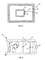
- the figure 9 represents the circuit diagram of an exemplary embodiment of the field detection electrical circuit connected to the secondary antenna 62.
- the block 67 represents the field detection circuit which is either in the chip 64 or directly integrated with the main chip 68
- the antenna 62, the capacitor 72 and the resistor 73 constitute an oscillating circuit tuned to the frequency of the reader, ie 13.56 MHz.
- the diode bridge 74 and the capacitor 75 serve to rectify and smooth the AC signal, available across the oscillating circuit.
- the voltage is continuous and dependent on the electromagnetic field to which the antenna is exposed.
- the zener diode 77 makes it possible to regulate the reference output voltage Vu and is itself protected from a too strong current by a resistor 76.
- the output voltage of the field detection circuit is applied at the input of the chip 68 by via the electrical connection 65 or not, and constitutes the logic signal mentioned above.
- the antenna 62 entering a carrier frequency field supplies the chip 64 and therefore the circuit 67, the output voltage goes to the reference value Vu. Since the antenna 62 is not in the carrier frequency field, no current passes through it and the circuit 64 delivers a zero voltage.
- the two antennas are directly connected to the main chip 68.
- the non-contact portable object 60 comprising the two devices enters the field of the reader 35 such that represented at figure 5 the two antennas 66 and 62 tuned in the same frequency band as the reader receive the energy necessary for their power supply.
- the energy supplied must be greater or sufficient for the proper functioning of the applications of the chips 68 and 64.
- the chip 64 consumes less energy than the chip 68 due to its lower triggering threshold provides the logic signal before the chip 68 is initialized.
- the antenna 62 is dimensioned and parameterized so that it firstly recovers the energy required to power the chip.
- the antenna 62 As soon as the antenna 62 enters the field, it firstly recovers the energy required to supply the chip 64 and thus to supply the field detection circuit 67 which delivers a voltage representing the logic signal.
- the main chip 68 is then instantaneously in a mode where no signal is exchanged with the reader making the main chip 68 mute and thus the reading of the data impossible.
- the field detection circuit When it is desired to read the data of the main chip 68 of the non-contact portable object, the field detection circuit must not be powered as a result, the antenna 62 must not be crossed by the electromagnetic field lines. emitted by the reader's antenna. For this, the non-contact portable object must be placed on a reader so that the secondary antenna 62 is masked.
- a booklet such as a passport
- the two antennas are each placed on a part of the mobile passport with respect to each other, the passport must be placed open in the same way as in the first one. embodiment on a reader 25 of the type described in Figures 2 and 3 . It can also be read on a reader 35 in the same way as in the example of the figure 7 previously described.
- the two antennas are placed on the same flat part, the reading of the data is done as in the example of Figures 4 to 6 previously described.
- the secondary radiofrequency device may comprise an antenna with two sets of turns, each set comprising at least one turn.
- the first set comprises one or more turns as large as the turn 12 defines for the secondary radiofrequency device of the figure 1 .
- the second set comprises one or more turns smaller than the size of the turns of the first set.
- the size of the turns of the second set preferably remains greater than the size of the turns of the antenna of the main radiofrequency device.
- the antenna of the secondary radiofrequency device thus comprises at least two sets of turns of different size.
Landscapes
- Engineering & Computer Science (AREA)
- Physics & Mathematics (AREA)
- Computer Hardware Design (AREA)
- General Physics & Mathematics (AREA)
- Theoretical Computer Science (AREA)
- Microelectronics & Electronic Packaging (AREA)
- Electromagnetism (AREA)
- General Engineering & Computer Science (AREA)
- Computer Security & Cryptography (AREA)
- Credit Cards Or The Like (AREA)
- Burglar Alarm Systems (AREA)
- Developing Agents For Electrophotography (AREA)
- Near-Field Transmission Systems (AREA)
- Radar Systems Or Details Thereof (AREA)
- Mechanical Treatment Of Semiconductor (AREA)
- Telephone Function (AREA)
- Looms (AREA)
Abstract
Description
La présente invention concerne un périphérique pour objet portable sans contact et concerne en particulier un périphérique de sécurité intégré à un objet sans contact de type document sécurisé à dispositif radiofréquence.The present invention relates to a device for portable object without contact and relates in particular to a security device integrated in a contactless object of the secure document type radiofrequency device.
Les dispositifs d'identification radiofréquence (RFID) sans contact sont de plus en plus utilisés pour l'identification des personnes circulant dans des zones à accès contrôlé ou transitant d'une zone à une autre. Le marché des documents sécurisés de type document d'identité tel que passeport, carte d'identité ou autre est de ce fait en plein essor. Un dispositif RFID sans contact est un dispositif constitué d'une antenne et d'une puce connectée aux bornes de l'antenne. La puce n'est généralement pas alimentée par piles (batteries) et reçoit son énergie par couplage électromagnétique entre l'antenne du lecteur et l'antenne du dispositif RFID, des informations sont échangées entre le dispositif RFID et le lecteur et en particulier les informations stockées dans la puce qui ont trait à l'identification du possesseur de l'objet sur lequel se trouve le dispositif RFID et son autorisation à pénétrer dans une zone à accès contrôlé.Non-contact radio frequency identification (RFID) devices are increasingly used for the identification of people traveling in areas with controlled access or transit from one area to another. The market for secure documents of the identity document type such as passport, identity card or other is therefore booming. A contactless RFID device is a device consisting of an antenna and a chip connected to the terminals of the antenna. The chip is generally not powered by batteries (batteries) and receives its energy by electromagnetic coupling between the antenna of the reader and the antenna of the RFID device, information is exchanged between the RFID device and the reader and in particular the information stored in the chip relating to the identification of the owner of the object on which the RFID device is located and its authorization to enter a controlled access zone.
Ainsi, les passeports peuvent incorporer des dispositifs RFID pour l'identification du possesseur du passeport. La mémoire de la puce contient des informations telles que l'identité du possesseur du passeport, son pays d'origine, sa nationalité, les visas des différents pays visités, les dates d'entrée, les restrictions de circulation, les éléments biométriques, etc. Afin d'inclure le dispositif RFID dans le passeport, il existe plusieurs solutions qui consiste soit à imprimer directement l'antenne sur le plat de la couverture du passeport et à y connecter la puce soit d'utiliser un élément extérieur appelé « inlay » comportant le dispositif RFID. Quelle que soit la solution, le dispositif RFID se trouve incorporé soit dans le plat de couverture inférieur du passeport soit dans le plat supérieur. Dans le cas d'une carte d'identité, l'antenne est directement sérigraphiée sur l'une des couches constitutives de la carte et la puce y est connectées. Un tel dispositif est décrit dans le document
L'accès aux données de la puce se fait par couplage électromagnétique à distance avec un lecteur muni également d'une antenne. Lorsque l'antenne du lecteur est alimentée elle est parcouru par un courant électrique qui engendre un flux électromagnétique. Pour être lu le livret d'identité est placé sur le lecteur sur un emplacement prévu à cet effet. Une fois le livret en place, l'antenne du livret est traversée par les lignes du champ électromagnétique émis par le lecteur, l'antenne alors accordée dans la même bande de fréquence que le lecteur reçoit l'énergie nécessaire à son alimentation, elle peut donc dialoguer avec le lecteur et échanger des données. Pour que la communication soit optimale, l'antenne du livret doit être placée parallèlement à l'antenne du lecteur et à une distance du lecteur qui doit être inférieure à la distance minimale requise pour qu'il y ait suffisamment d'énergie pour faire fonctionner la puce.The access to the data of the chip is done by remote electromagnetic coupling with a reader also provided with an antenna. When the antenna of the reader is powered it is traversed by an electric current that generates an electromagnetic flow. To be read the identity booklet is placed on the reader on a space provided for this purpose. Once the booklet is in place, the antenna of the booklet is crossed by the lines of the electromagnetic field emitted by the reader, the antenna then tuned in the same frequency band that the reader receives the energy necessary for its power supply, it can therefore dialogue with the reader and exchange data. For optimum communication, the booklet antenna must be placed parallel to the reader antenna and at a distance from the reader that must be less than the minimum distance required for sufficient power to operate. the chip.
Le problème majeur qui se pose de façon commune aux documents sécurisés sans contact en général, et en particulier aux documents sécurisés qui contiennent des informations personnelles de type état civil ou biométrique, est la confidentialité des informations contenues dans le dispositif RFID incorporé dans la puce du document. L'accès aux données contenues dans la puce doit pouvoir être maîtrisé et contrôlé, et ce, en particulier lorsque le document sécurisé n'est pas utilisé afin que les données confidentielles ne soient pas récupérées à l'insu du porteur du document.The major problem that commonly arises for contactless secure documents in general, and in particular for secure documents that contain personal information of the civil or biometric type, is the confidentiality of the information contained in the RFID device incorporated in the chip of the document. Access to the data contained in the chip must be controlled and controlled, especially when the secure document is not used so that the confidential data are not retrieved without the knowledge of the document holder.
Une solution existe telle que décrite dans le document
L'inconvénient d'un tel dispositif réside dans le fait que l'action sur le couplage entre le transpondeur et le lecteur n'agit pas tel qu'un interrupteur en tout ou rien mais agit de façon à atténuer le signal afin de minimiser le couplage entre le transpondeur et le lecteur. De plus, l'atténuation du signal est fonction de la fréquence du signal, l'atténuation sera d'autant plus grande que la fréquence du signal est élevée ; or la fréquence de fonctionnement des documents sécurisés est 13,56 MHz telle que définie dans les normes ISO 14443 et 15693. L'atténuation du signal est également fonction des caractéristiques de l'élément de masquage tel que son épaisseur et sa conductivité électrique, mais aussi est fonction de la distance entre l'élément passif et l'antenne du dispositif RFID. Plus l'élément de masquage passif est prêt de l'antenne et plus il est efficace.The disadvantage of such a device lies in the fact that the action on the coupling between the transponder and the reader does not act as an on / off switch but acts to attenuate the signal in order to minimize the coupling between the transponder and the reader. In addition, the attenuation of the signal is a function of the frequency of the signal, the attenuation will be greater as the frequency of the signal is high; however the operating frequency of the secured documents is 13.56 MHz as defined in ISO 14443 and 15693. The attenuation of the signal is also a function of the characteristics of the masking element such as its thickness and its electrical conductivity, but also is a function of the distance between the passive element and the antenna of the RFID device. The more the passive masking element is ready for the antenna, the more effective it is.
Le niveau d'atténuation du signal dépendra donc de la façon dont le document sécurisé est maintenu fermé. Par conséquent, un passeport disposé dans un sac et légèrement ouvert pourra être lu à l'insu de son porteur. De même, un passeport dont les pages sont épaisses du fait de l'usure ou de la présence de visas diminuera l'efficacité de l'élément de masquage passif. Le niveau d'atténuation du signal dépend également de l'épaisseur du passeport.The level of attenuation of the signal will therefore depend on how the secure document is kept closed. Therefore, a passport placed in a bag and slightly open can be read without the knowledge of its holder. Similarly, a passport whose pages are thick due to wear or the presence of visas will reduce the effectiveness of the passive masking element. The level of attenuation of the signal also depends on the thickness of the passport.
En outre, la distance minimale de lecture entre le passeport et le lecteur varie en fonction du niveau du champ électromagnétique émis par l'antenne du lecteur. L'efficacité de la communication entre le lecteur et le passeport varie donc selon le champ émis par le lecteur. Cela signifie que même lorsqu'il est équipé d'un masquage passif, le passeport peut être lu avec un lecteur adéquat puisque un masquage passif permet en fait de réduire la distance de lecture. Cette solution ne garantit donc pas au porteur du passeport l'impossibilité d'une lecture intempestive.In addition, the minimum distance of reading between the passport and the reader varies according to the level of the electromagnetic field emitted by the antenna of the reader. The effectiveness of the communication between the reader and the passport therefore varies according to the field emitted by the reader. This means that even when equipped with passive masking, the passport can be read with an adequate reader since passive masking actually reduces the reading distance. This solution therefore does not guarantee the holder of the passport the impossibility of an untimely reading.
C'est pourquoi le but de l'invention est de fournir un dispositif qui empêche la lecture intempestive des données contenues dans un objet sans contact de type document sécurisé à dispositif radiofréquence tout en palliant aux inconvénients précités.This is why the object of the invention is to provide a device which prevents the unwanted reading of the data contained in a non-contact object of secure document type radio frequency device while overcoming the aforementioned drawbacks.
L'objet de l'invention est donc un objet portable sans contact comprenant un dispositif radiofréquence principale composé d'une puce principale et d'une antenne principale connectées ensemble de sorte que lorsque l'objet portable rentre dans le champ magnétique d'un lecteur adapté, le dispositif radiofréquence principale assure l'alimentation de la puce et la communication entre la puce et le lecteur. Selon.la caractéristique principale de l'invention, l'objet portable comprend un dispositif secondaire sans contact comprenant une antenne secondaire et un circuit électrique paramétrées de façon à ce que, lorsque les deux antennes rentrent en même temps dans le champ magnétique d'un lecteur adapté, la quantité d'énergie nécessaire pour alimenter le circuit électrique de façon à le faire fonctionner étant inférieure à la quantité d'énergie nécessaire pour alimenter la puce principale de façon à la faire fonctionner, le circuit électrique est alimenté et rend impossible la lecture des données de la puce principale.The object of the invention is therefore a non-contact portable object comprising a main radiofrequency device composed of a main chip and a main antenna connected together so that when the portable object enters the magnetic field of a reader adapted, the main radiofrequency device ensures the supply of the chip and the communication between the chip and the reader. According to the main feature of the invention, the portable object comprises a non-contact secondary device comprising a secondary antenna and an electrical circuit parameterized so that, when the two antennas at the same time enter the magnetic field of a adapted reader, the amount of energy required to power the electrical circuit so as to operate is less than the amount of energy required to power the main chip so as to operate, the electrical circuit is powered and makes it impossible to read data from the main chip.
Les buts, objets et caractéristiques de l'invention apparaîtront plus clairement à la lecture de la description qui suit faite en référence aux dessins dans lesquels :
- La
figure 1 représente un passeport selon un premier mode de réalisation de l'invention, - La
figure 2 représente un premier lecteur de dispositif radiofréquence tel qu'un passeport, - La
figure 3 représente le passeport et le premier lecteur lors d'une lecture volontaire, - La
figure 4 représente une carte d'identité selon une variante du premier mode de réalisation de l'invention, - La
figure 5 représente un second lecteur de dispositif radiofréquence tel qu'un carte d'identité, - La
figure 6 représente la carte d'identité et le second lecteur lors d'une lecture volontaire, - La
figure 7 représente le passeport et le second lecteur lors d'une lecture volontaire, - La
figure 8 représente une carte d'identité selon le second mode de réalisation de l'invention.
- The
figure 1 represents a passport according to a first embodiment of the invention, - The
figure 2 represents a first radio frequency device reader such as a passport, - The
figure 3 represents the passport and the first reader during a voluntary reading, - The
figure 4 represents an identity card according to a variant of the first embodiment of the invention, - The
figure 5 represents a second radiofrequency device reader such as an identity card, - The
figure 6 represents the identity card and the second reader during a voluntary reading, - The
figure 7 represents the passport and the second reader during a voluntary reading, - The
figure 8 represents an identity card according to the second embodiment of the invention.
Selon la
Le passeport 10 comprend également une seconde antenne 12 connectée à un circuit électrique par exemple contenu dans une seconde puce électronique 14, l'antenne étant disposée sur la seconde couverture du livret, celle qui ne comporte pas le dispositif radiofréquence principal. La seconde antenne 12 et la seconde puce 14 constituent dans toute la suite de la description le dispositif radiofréquence secondaire. Sur la
Le lecteur utilisé pour la lecture du passeport présente une face plane de lecture destinée à recevoir le document à lire par couplage électromagnétique à distance. Le lecteur permet la réception et la transmission des signaux radiofréquences avec le dispositif sans contact donc avec le livret d'identité lorsque celui-ci est placé sur le lecteur de façon à ce que l'antenne principale 16 du passeport soit traversée par les lignes de champ magnétiques émises par le'lecteur, la puce principale est alors alimentée et l'échange des données entre le dispositif radiofréquence principal et le lecteur est possible. Cependant, pour ne pas empêcher la lecture des données de la puce principale 18, la puce secondaire 14 ne doit pas recevoir d'énergie de façon à n'émettre aucunes données. Pour cela, l'antenne 12 ne doit pas rentrer dans le champ magnétique émis par le lecteur de façon à ne pas être traversée par un courant, ce but est atteint par différents moyens selon les modèles des lecteurs.The reader used for reading the passport has a flat reading face intended to receive the document to be read by remote electromagnetic coupling. The reader allows reception and transmission of radio frequency signals with the contactless device so with the identity booklet when it is placed on the reader so that the
Le modèle de lecteur représenté sur les
En référence aux
En position fermée du passeport, les lignes du champ électromagnétique émis par le lecteur traversent à la fois l'antenne 12 et l'antenne 18. Donc le porteur du passeport peut être sûr que les données personnelles contenues dans son passeport ne seront pas lues à son insu lorsque le passeport est en position fermée. Si le porteur a malencontreusement laissé son passeport en position ouverte ou même légèrement ouvert dans son sac ou dans sa poche, si le passeport se trouve près du lecteur ou éloigné de celui-ci le résultat n'est pas le même. En champ lointain, c'est à dire lorsque le passeport se trouve loin du lecteur, les deux antennes 16 et 12 sont forcément traversées par les lignes du champ électromagnétique émis par le lecteur et comme pour le cas où le passeport est fermé, les données émises à la fois par la puce 14 et par la puce 18 se superposeront et rendront la lecture des données utiles impossible. En revanche, lorsque le porteur du passeport présentera volontairement son passeport, celui-ci pour être lu devra être positionné sur un lecteur approprié qui permettra la lecture uniquement lorsque le passeport est en position ouverte. La lecture des données utiles se fait donc lorsque la puce 18 est alimentée par l'antenne 16 et que la puce 14 n'est pas alimentée. L'antenne 12 ne doit donc pas rentrer dans le champ émis par le lecteur ce qui impose certaines manipulations du passeport par rapport au lecteur. le passeport est présenté sur la partie active de la face d'un lecteur à plat de façon à ce que seule la moitié du passeport comportant l'antenne et la puce principales soient en regard de l'antenne du lecteur. Ainsi pour être lu, le passeport 10 est présenté sur le lecteur ouvert, de façon à ce que la face arrière du passeport soit contre le lecteur comme mentionnée sur la
Dans le cas où le document sécurisé est un objet portable sans contact de type carte d'identité 30 comme illustré sur la
Le lecteur 35 représenté sur la
Le lecteur 35 est muni de moyens pour que l'antenne secondaire 32 du dispositif radiofréquence secondaire ne soit pas traversée par les lignes de champ électromagnétique émises par le lecteur lorsque le dispositif sans contact est placé contre la face de lecture 31 du lecteur. Un moyen utilisé pour que l'antenne secondaire 32 du dispositif radiofréquence secondaire ne soit pas traversé par les lignes de champ électromagnétiques émises par le lecteur est représenté sur la
De cette façon, le lecteur 35 assure la réception et la transmission des signaux radiofréquences avec le dispositif sans contact donc avec le dispositif radiofréquence principal de la carte d'identité lorsque celle-ci est placée contre sa face de lecture 31 comme représenté sur la
Dans le cas d'un dispositif sans contact tel que le passeport décrit sur la
Selon un second mode de réalisation de l'invention et en référence à la figure schématique 8, les deux dispositifs radiofréquence principal et secondaire sont connectés ensemble. Le dispositif radiofréquence principal comporte une puce 68 et une antenne 66 connectées ensemble, la puce 68 étant comme pour le premier mode de réalisation la puce principale contenant les données personnelles d'identification du porteur de l'objet portable. De ce fait, la puce électronique 68 comprend plusieurs fonctions complexes destinées à traiter les informations en provenance du lecteur. Ainsi, pour pouvoir interpréter, stocker et comparer les informations et dialoguer avec le lecteur, la puce contient un micro contrôleur, de la mémoire, une unité d'entrée/sortie, etc.... Le dispositif radiofréquence secondaire est composé d'un circuit électrique,par exemple contenu dans une puce 64 et d'une antenne 62.According to a second embodiment of the invention and with reference to the schematic figure 8, the two main and secondary radiofrequency devices are connected together. The main radiofrequency device comprises a
Le circuit électrique de la puce 64 est un circuit simple tel qu'un circuit de détection de champ et donc ne contient ni micro contrôleur, ni mémoire, elle est par conséquent beaucoup moins complexe que la puce 68 de sorte que son seuil de déclenchement pour rentrer en phase active est beaucoup plus bas que la puce 68, en d'autre terme, la quantité d'énergie nécessaire pour alimenter la puce 64 de façon à la faire fonctionner est inférieure à la quantité d'énergie nécessaire pour alimenter la puce 68 de façon à la faire fonctionner. Par conséquent, la puce 64 consommant moins d'énergie que la puce 68 est alimentée la première.The electrical circuit of the
Le circuit électrique tel que le circuit de détection de champ peut être intégré directement à la puce principal. Dans ce cas, il s'agit d'une puce à deux étages d'entrée un pour chacun des deux dispositifs. Le circuit de détection de champ permet par exemple de générer un niveau de tension de référence Vu (par exemple 5V) en présence du champ du lecteur afin de fournir un signal logique de désactivation de la fonctionnalité principale de la puce 68 de façon à la rendre muette. Le signal logique de désactivation est exploité par la puce 68 dés que celle-ci est alimentée de sorte que toute communication avec le lecteur est empêchée si le signal de désactivation est présent. Le signal logique de désactivation fournit par le circuit électrique 67 est émis avant que la puce principale 68 ne réponde car la quantité d'énergie nécessaire pour alimenter le circuit électrique 67 de façon à le faire fonctionner est inférieure à la quantité d'énergie nécessaire pour alimenter la puce 68 de façon à la faire fonctionner. Par conséquent, le circuit électrique 67 consommant moins d'énergie que la puce 68 est alimenté le premier. Certaines cartes à puce hybrides, c'est à dire fonctionnant à la fois en contact et en sans contact utilisent un principe de sélection équivalent au démarrage pour faire le choix entre l'application de la fonction contact ou bien de la fonction sans contact. Le dispositif selon l'invention reprend ce principe pour sélectionner au démarrage la poursuite normale de l'application contenue dans la puce principale ou bien sa suspension ou encore l'interdiction des communications.The electrical circuit such as the field detection circuit can be integrated directly to the main chip. In this case, it is a two-stage input chip one for each of the two devices. The field detection circuit makes it possible, for example, to generate a reference voltage level Vu (for example 5V) in the presence of the reader field in order to provide a logic signal for deactivating the main functionality of the
La puce principale 68 comprend dans son système d'exploitation une fonction déclenchée dés l'initialisation de la puce pour tester le signal logique de détection de champ fournit par la puce secondaire 64. Selon le résultat du test, l'application contenu dans le système d'exploitation de la puce principale 68 continue son exécution ou stoppe. En effet, la puce possède deux systèmes d'entrée dont l'un est prioritaire sur l'autre. Les deux dispositifs radiofréquence sont connectés ensembles par exemple par une connexion électrique 65 entre le circuit de détection de champ de la puce 64 et la puce 68 ou entre l'antenne 62 et la puce principale 68 dans le cas où le circuit de détection de champ est directement intégré à la puce 68.The
Comme pour le premier mode de réalisation de l'invention, le second mode peut s'appliquer à tout type d'objet portable sans contact tel qu'un document sécurisé muni d'un dispositif radiofréquence. Selon la
La
Si le circuit de détection de puce est directement intégré à la puce principale 68, les deux antennes sont directement connectées à la puce principale 68. Lorsque l'objet portable sans contact 60 comportant les deux dispositifs rentre dans le champ du lecteur 35 tel que représenté à la
Lorsque l'on veut lire les données de la puce principale 68 de l'objet portable sans contact, le circuit de détection de champ ne doit pas être alimenté par conséquent, l'antenne 62 ne doit pas être traversée par les lignes de champ électromagnétique émise par l'antenne du lecteur. Pour cela, l'objet portable sans contact doit être placé sur un lecteur de sorte que l'antenne secondaire 62 soit masquée. Dans le cas d'un livret tel qu'un passeport, si les deux antennes sont placées chacune sur une partie du passeport mobile l'une par rapport à l'autre, le passeport doit être placé ouvert de la même façon que dans le premier mode de réalisation sur un lecteur 25 du type de celui décrit dans les
Selon une variante de réalisation du dispositif selon le mode préféré de l'invention, le dispositif radiofréquence secondaire peut comporter une antenne à deux ensembles de spires, chaque ensemble comportant au moins une spire. Le premier ensemble comporte une ou plusieurs spires aussi grande que la spire 12 définit pour le dispositif radiofréquence secondaire de la
Claims (11)
- A contactless portable object (10, 30, 60) featuring a main radiofrequency device made up of a main chip (18, 38, 68) and a main antenna (16, 36, 66) connected together so that when the portable object enters the magnetic field of a suitable reader, the main radiofrequency device provides power to the chip and ensures communication between the chip and the reader and a secondary contactless device featuring a secondary antenna (12, 32, 62) and an electric circuit;
characterized in that the secondary antenna and the electric circuit are set up in such a way that, when the two antennas enter the magnetic field of a suitable reader at the same time, the amount of energy required to power said electric circuit and have it operational being less than the amount of energy required to power the main chip (18, 38, 68) and have it operational, said electric circuit is powered and makes the reading of data of the main chip impossible. - The contactless portable object according to claim 1, in which the electric circuit is contained in a secondary chip (14, 34, 64).
- The portable object according to claim 1 or 2, in which said electric circuit (14) transmits random data as soon as it receives the energy required for its operation so that the transmission of random data occurs before the main chip (18) can exchange data with the reader.
- The portable object according to claim 1, 2, or 3, in which the secondary antenna (62) is connected to the main radiofrequency device.
- The contactless portable object according to claim 4, in which said electric circuit is a field detection circuit.
- The contactless portable object according to claim 6, in which the field detection circuit allows a voltage of 5V to be generated in the presence of the field of the reader in order to provide a logical signal for deactivating the main function of the chip (68) to make it silent.
- The portable object according to any of claims 1 to 6 in which the secondary antenna (12) features at least two set of turns with different sizes.
- The booklet such as a passport (10) defined according to any of claims 1 to 7.
- The identity card (30, 60) according to any of claims 1 to 7.
- The radiofrequency reader (20) featuring a reading face (24, 31) consisting of an active part (26) housing an antenna (28, 36) and a passive part (27, 37) housing an antenna masking element, the reader being adapted to read the data contained in the contactless portable object according to any of claims 1 to 9 when the part of the contactless portable object containing the main radiofrequency device is placed against the active part (26) of the reader whereas the secondary contactless device is placed against the passive part.
- The reader according to claim 10, in which the passive part (27, 37) houses a metal plate whose dimension is such that it superimposes on the secondary antenna so as to completely cover the surface area defined by the antenna.
Applications Claiming Priority (2)
| Application Number | Priority Date | Filing Date | Title |
|---|---|---|---|
| FR0607297A FR2904880B1 (en) | 2006-08-11 | 2006-08-11 | SECURITY DEVICE INTEGRATED WITH CONTACTLESS OBJECT OF SECURE DOCUMENT TYPE WITH RADIO FREQUENCY DEVICE. |
| PCT/FR2007/001359 WO2008020125A1 (en) | 2006-08-11 | 2007-08-10 | Security peripheral integrated with a contactless object of secure document type with radiofrequency device |
Publications (2)
| Publication Number | Publication Date |
|---|---|
| EP2057588A1 EP2057588A1 (en) | 2009-05-13 |
| EP2057588B1 true EP2057588B1 (en) | 2010-09-15 |
Family
ID=37831463
Family Applications (1)
| Application Number | Title | Priority Date | Filing Date |
|---|---|---|---|
| EP07823411A Revoked EP2057588B1 (en) | 2006-08-11 | 2007-08-10 | Security peripheral integrated with a contactless object of secure document type with radiofrequency device |
Country Status (17)
| Country | Link |
|---|---|
| US (1) | US8550360B2 (en) |
| EP (1) | EP2057588B1 (en) |
| JP (1) | JP2010500638A (en) |
| KR (1) | KR101351907B1 (en) |
| CN (1) | CN101523423B (en) |
| AT (1) | ATE481691T1 (en) |
| BR (1) | BRPI0715749A2 (en) |
| CA (1) | CA2660662A1 (en) |
| DE (1) | DE602007009263D1 (en) |
| ES (1) | ES2358758T3 (en) |
| FR (1) | FR2904880B1 (en) |
| HK (1) | HK1135786A1 (en) |
| IL (1) | IL196985A (en) |
| MX (1) | MX2009001569A (en) |
| PT (1) | PT2057588E (en) |
| TW (1) | TWI460663B (en) |
| WO (1) | WO2008020125A1 (en) |
Families Citing this family (16)
| Publication number | Priority date | Publication date | Assignee | Title |
|---|---|---|---|---|
| US20090159709A1 (en) * | 2007-12-24 | 2009-06-25 | Dynamics Inc. | Advanced dynamic credit cards |
| JP4937989B2 (en) * | 2008-11-26 | 2012-05-23 | 京セラ株式会社 | Portable electronic devices |
| CN102282574B (en) | 2008-12-15 | 2015-06-03 | 卡德赖博私人有限公司 | An RFID tag |
| IT1401521B1 (en) * | 2010-08-11 | 2013-07-26 | St Microelectronics Srl | SAFETY SYSTEM FOR AT LEAST AN INTEGRATED CIRCUIT IC, SAFETY INTEGRATED CIRCUIT BOARD AND SAFETY WIRELESS COMMUNICATION METHOD. |
| CN102957454B (en) * | 2011-08-26 | 2014-12-17 | 国民技术股份有限公司 | Method and system for utilizing magnetic bidirectional communication |
| US8950681B2 (en) | 2011-11-07 | 2015-02-10 | Blackberry Limited | Universal integrated circuit card apparatus and related methods |
| USD691610S1 (en) | 2011-11-07 | 2013-10-15 | Blackberry Limited | Device smart card |
| US8763914B2 (en) * | 2012-01-17 | 2014-07-01 | On Track Innovations Ltd. | Decoupled contactless bi-directional systems and methods |
| US9177181B2 (en) | 2012-04-19 | 2015-11-03 | Infineon Technologies Ag | Secure epass booklet based on double chip technology |
| JP5942658B2 (en) * | 2012-07-20 | 2016-06-29 | 凸版印刷株式会社 | Information record booklet |
| CN104933460A (en) * | 2014-03-20 | 2015-09-23 | 中兴通讯股份有限公司 | RFID label and device for dynamically starting RFID label |
| CN107209846A (en) | 2014-12-19 | 2017-09-26 | 卡德赖博私人有限公司 | Method for generating the method and component in magnetic field and manufacturing component |
| EP3035230A1 (en) | 2014-12-19 | 2016-06-22 | Cardlab ApS | A method and an assembly for generating a magnetic field |
| US20160183487A1 (en) * | 2014-12-24 | 2016-06-30 | Microware Limited | System and Method for Detecting the Absence of a Thin Nutrient Film in a Plant Growing Trough |
| EP3082071A1 (en) | 2015-04-17 | 2016-10-19 | Cardlab ApS | Device for and method of outputting a magnetic field |
| FR3084978B1 (en) * | 2018-08-10 | 2020-07-17 | Uwinloc | RADIO FREQUENCY ENERGY COLLECTION CIRCUIT AND COMMUNICATION DEVICE INCLUDING SUCH A RADIO FREQUENCY COLLECTION CIRCUIT |
Family Cites Families (26)
| Publication number | Priority date | Publication date | Assignee | Title |
|---|---|---|---|---|
| US4385285A (en) * | 1981-04-02 | 1983-05-24 | Ncr Corporation | Check dispensing terminal |
| US5023782A (en) * | 1990-03-26 | 1991-06-11 | Mastercard International Inc. | Travelers cheque transaction terminal |
| US5777305A (en) * | 1996-01-24 | 1998-07-07 | Incomm | Package assembly and method for activating prepaid debit cards |
| US5863073A (en) * | 1996-11-14 | 1999-01-26 | American Express Travel Related Services | Refundable travellers cheques |
| JP4066520B2 (en) * | 1997-12-18 | 2008-03-26 | 株式会社デンソー | Non-contact IC card reader / writer |
| US6328341B2 (en) * | 2000-03-07 | 2001-12-11 | Western Graphics And Data, Inc. | Multiple-component data package |
| WO2003079261A1 (en) * | 2002-03-08 | 2003-09-25 | First Data Corporation | Card-based system and method for issuing negotiable instruments |
| US20020100797A1 (en) * | 2001-02-01 | 2002-08-01 | Hollingsworth James R. | Gift card envelope |
| AU2002237816A1 (en) * | 2002-01-08 | 2003-07-30 | Riverborne Communications, Llc | Point-of-sale activation and subsequent registration of products |
| JP4201635B2 (en) * | 2003-04-04 | 2008-12-24 | ソニー・エリクソン・モバイルコミュニケーションズ株式会社 | Non-contact IC card |
| US7446646B2 (en) * | 2003-06-30 | 2008-11-04 | Nokia Corporation | System and method for supporting multiple reader-tag configurations using multi-mode radio frequency tag |
| CN1886750A (en) * | 2003-11-27 | 2006-12-27 | 皇家飞利浦电子股份有限公司 | Jammer for tags and smart cards |
| US7421245B2 (en) * | 2004-02-20 | 2008-09-02 | 3M Innovative Properties Company | Field-shaping shielding for radio frequency identification (RFID) system |
| US7243839B2 (en) * | 2004-03-12 | 2007-07-17 | American Express Travel Related Services Company, Inc. | Systems, methods, and devices for selling transaction instruments |
| US7132946B2 (en) * | 2004-04-08 | 2006-11-07 | 3M Innovative Properties Company | Variable frequency radio frequency identification (RFID) tags |
| US20060005050A1 (en) * | 2004-06-10 | 2006-01-05 | Supercom Ltd. | Tamper-free and forgery-proof passport and methods for providing same |
| FR2871603B1 (en) * | 2004-06-11 | 2006-09-29 | K Sa As | SECURE RADIOFREQUENCY IDENTIFICATION DEVICE FOR AN IDENTITY OR IDENTIFIER BOOKLET |
| WO2006005984A1 (en) * | 2004-06-16 | 2006-01-19 | Axalto Sa | Shielded contactless electronic document |
| JP4398835B2 (en) | 2004-09-29 | 2010-01-13 | 株式会社東芝 | Passbook for personal authentication |
| FR2879789B1 (en) * | 2004-12-17 | 2008-07-18 | Francois Charles Oberthur Fidu | SECURITY DOCUMENT PROVIDED WITH MEANS FOR ELECTROMAGNETIC FIELD DISTURBANCE |
| WO2006107397A2 (en) * | 2005-02-07 | 2006-10-12 | Steven Colby | Radio frequency shielding |
| FR2888367B1 (en) * | 2005-07-07 | 2007-10-19 | Oberthur Card Syst Sa | DOCUMENT WITH INTEGRATED CONTACTLESS ELECTRONIC DEVICE WITH RESONATOR. |
| FR2888368B1 (en) * | 2005-07-07 | 2007-10-05 | Oberthur Card Syst Sa | FOLDABLE DOCUMENT WITH CONTACTLESS CONTACTLESS ELECTRONIC DEVICE |
| FR2888652B1 (en) * | 2005-07-18 | 2007-10-12 | Oberthur Card Syst Sa | ACTIVE SECURING METHOD AND DEVICE FOR NON-CONTACT ELECTRONIC DEVICE |
| US7889056B2 (en) * | 2005-10-31 | 2011-02-15 | Curio, Ltd. | RFID protection system, device, combination, and related methods |
| FR2901899B1 (en) | 2006-06-06 | 2009-05-08 | Ask Sa | MASKING DEVICE FOR NON-CONTACT PORTABLE OBJECT OF SECURE DOCUMENT TYPE WITH RADIO FREQUENCY DEVICE |
-
2006
- 2006-08-11 FR FR0607297A patent/FR2904880B1/en active Active
-
2007
- 2007-08-10 BR BRPI0715749-5A patent/BRPI0715749A2/en not_active Application Discontinuation
- 2007-08-10 WO PCT/FR2007/001359 patent/WO2008020125A1/en active Application Filing
- 2007-08-10 MX MX2009001569A patent/MX2009001569A/en active IP Right Grant
- 2007-08-10 DE DE602007009263T patent/DE602007009263D1/en active Active
- 2007-08-10 US US11/837,063 patent/US8550360B2/en active Active
- 2007-08-10 JP JP2009523318A patent/JP2010500638A/en active Pending
- 2007-08-10 CN CN200780036611XA patent/CN101523423B/en active Active
- 2007-08-10 AT AT07823411T patent/ATE481691T1/en not_active IP Right Cessation
- 2007-08-10 PT PT07823411T patent/PT2057588E/en unknown
- 2007-08-10 CA CA002660662A patent/CA2660662A1/en not_active Abandoned
- 2007-08-10 KR KR1020097002838A patent/KR101351907B1/en active IP Right Grant
- 2007-08-10 EP EP07823411A patent/EP2057588B1/en not_active Revoked
- 2007-08-10 ES ES07823411T patent/ES2358758T3/en active Active
- 2007-08-13 TW TW096129803A patent/TWI460663B/en active
-
2009
- 2009-02-09 IL IL196985A patent/IL196985A/en active IP Right Grant
-
2010
- 2010-03-02 HK HK10102219.9A patent/HK1135786A1/en not_active IP Right Cessation
Also Published As
| Publication number | Publication date |
|---|---|
| DE602007009263D1 (en) | 2010-10-28 |
| FR2904880A1 (en) | 2008-02-15 |
| US20080128514A1 (en) | 2008-06-05 |
| TWI460663B (en) | 2014-11-11 |
| WO2008020125A1 (en) | 2008-02-21 |
| PT2057588E (en) | 2010-12-22 |
| KR101351907B1 (en) | 2014-01-23 |
| FR2904880B1 (en) | 2008-10-10 |
| TW200818026A (en) | 2008-04-16 |
| ES2358758T3 (en) | 2011-05-13 |
| CN101523423A (en) | 2009-09-02 |
| MX2009001569A (en) | 2009-02-19 |
| BRPI0715749A2 (en) | 2013-07-09 |
| ATE481691T1 (en) | 2010-10-15 |
| IL196985A (en) | 2013-06-27 |
| EP2057588A1 (en) | 2009-05-13 |
| KR20090045235A (en) | 2009-05-07 |
| HK1135786A1 (en) | 2010-06-11 |
| JP2010500638A (en) | 2010-01-07 |
| IL196985A0 (en) | 2009-11-18 |
| CA2660662A1 (en) | 2008-02-21 |
| US8550360B2 (en) | 2013-10-08 |
| CN101523423B (en) | 2013-10-30 |
Similar Documents
| Publication | Publication Date | Title |
|---|---|---|
| EP2057588B1 (en) | Security peripheral integrated with a contactless object of secure document type with radiofrequency device | |
| EP1918859B1 (en) | Device for protection against fraud in contactless communication objects | |
| CA2382451C (en) | Contact-free portable object comprising one or several contact-free peripheral devices | |
| FR2989802B1 (en) | CARD WITH DISPLAY FUNCTION HAVING SECURITY AUTHENTICATION FUNCTION | |
| FR2752076A1 (en) | ELECTRICAL SUPPLY SYSTEM FOR MICROCIRCUIT WITH MIXED OPERATION, WITH OR WITHOUT CONTACT | |
| FR2953619A1 (en) | ACTIVATION AND INDICATION OF RF FIELD ON A DEVICE COMPRISING A CHIP. | |
| EP1857953A1 (en) | Method and system for authentication and secure exchange of data between a personalised chip and a dedicated server | |
| EP1904960B1 (en) | Device for providing active security to a contact-free electronic device | |
| EP2065857A2 (en) | Microprocessor card, telephone comprising such a card and method of executing a command on such a card | |
| FR2968801A1 (en) | CONTACT WITHOUT CONTACT WITH AUTHORIZATION BY HUMAN CONTACT | |
| FR2910746A1 (en) | Local radio-frequency communication interface for e.g. mobile telephone, has antenna connected to another set of antennas to allow smart card communicating with non-contact reader without using wireless telecommunication network | |
| FR2901899A1 (en) | MASKING DEVICE FOR NON-CONTACT PORTABLE OBJECT OF SECURE DOCUMENT TYPE WITH RADIO FREQUENCY DEVICE | |
| CA2439516A1 (en) | Non-contact portable object comprising at least a peripheral device coneected to the same antenna as the chip | |
| FR2968802A1 (en) | CONTACTLESS COMMUNICATION WITH HUMAN CONTACT AUTHORIZATION AND VISUAL INDICATOR | |
| EP3108424A1 (en) | Electronic transaction method and system via a portable accessory | |
| EP3110190B1 (en) | Method and device for managing contactless applications | |
| WO2006035177A1 (en) | Contactless privacy protection device | |
| FR2968803A1 (en) | Electromagnetic transponder e.g. dual integrated circuit card, for contactless exchanging of protected data with reader for bank card, has electric circuit switched from one state to another state when resonant circuit is powered by reader | |
| EP2600287A1 (en) | Electronic device including elements managed by various standardised protocols and method for managing communication between said elements | |
| FR2969877A1 (en) | High security data encryption device for data encryption of radio frequency identification tag, has radio frequency identification reader integrated in mobile phone to read encryption key or decryption key stored on tag | |
| FR2901897A1 (en) | Masking device for e.g. passport, has concentric closed loops or turns formed on support made of paper or synthetic material, where device prevents reading of data from chip of radiofrequency device when it is placed near aerial | |
| FR3095111A1 (en) | CONNECTED ELECTRONIC CARD HOLDER AND CARD MANAGEMENT SYSTEM | |
| FR2865339A1 (en) | Personal data protecting method for e.g. portable computer, involves writing personal data in scratchpad memory of radio frequency identification tag after verifying identification of tag, while creating or modifying data |
Legal Events
| Date | Code | Title | Description |
|---|---|---|---|
| PUAI | Public reference made under article 153(3) epc to a published international application that has entered the european phase |
Free format text: ORIGINAL CODE: 0009012 |
|
| 17P | Request for examination filed |
Effective date: 20090302 |
|
| AK | Designated contracting states |
Kind code of ref document: A1 Designated state(s): AT BE BG CH CY CZ DE DK EE ES FI FR GB GR HU IE IS IT LI LT LU LV MC MT NL PL PT RO SE SI SK TR |
|
| AX | Request for extension of the european patent |
Extension state: AL BA HR MK RS |
|
| 17Q | First examination report despatched |
Effective date: 20090529 |
|
| GRAP | Despatch of communication of intention to grant a patent |
Free format text: ORIGINAL CODE: EPIDOSNIGR1 |
|
| DAX | Request for extension of the european patent (deleted) | ||
| GRAS | Grant fee paid |
Free format text: ORIGINAL CODE: EPIDOSNIGR3 |
|
| GRAA | (expected) grant |
Free format text: ORIGINAL CODE: 0009210 |
|
| AK | Designated contracting states |
Kind code of ref document: B1 Designated state(s): AT BE BG CH CY CZ DE DK EE ES FI FR GB GR HU IE IS IT LI LT LU LV MC MT NL PL PT RO SE SI SK TR |
|
| REG | Reference to a national code |
Ref country code: GB Ref legal event code: FG4D Free format text: NOT ENGLISH Ref country code: CH Ref legal event code: EP |
|
| REG | Reference to a national code |
Ref country code: IE Ref legal event code: FG4D Free format text: LANGUAGE OF EP DOCUMENT: FRENCH |
|
| REF | Corresponds to: |
Ref document number: 602007009263 Country of ref document: DE Date of ref document: 20101028 Kind code of ref document: P |
|
| REG | Reference to a national code |
Ref country code: PT Ref legal event code: SC4A Free format text: AVAILABILITY OF NATIONAL TRANSLATION Effective date: 20101215 |
|
| REG | Reference to a national code |
Ref country code: NL Ref legal event code: VDEP Effective date: 20100915 |
|
| PG25 | Lapsed in a contracting state [announced via postgrant information from national office to epo] |
Ref country code: LT Free format text: LAPSE BECAUSE OF FAILURE TO SUBMIT A TRANSLATION OF THE DESCRIPTION OR TO PAY THE FEE WITHIN THE PRESCRIBED TIME-LIMIT Effective date: 20100915 Ref country code: FI Free format text: LAPSE BECAUSE OF FAILURE TO SUBMIT A TRANSLATION OF THE DESCRIPTION OR TO PAY THE FEE WITHIN THE PRESCRIBED TIME-LIMIT Effective date: 20100915 Ref country code: AT Free format text: LAPSE BECAUSE OF FAILURE TO SUBMIT A TRANSLATION OF THE DESCRIPTION OR TO PAY THE FEE WITHIN THE PRESCRIBED TIME-LIMIT Effective date: 20100915 |
|
| LTIE | Lt: invalidation of european patent or patent extension |
Effective date: 20100915 |
|
| PG25 | Lapsed in a contracting state [announced via postgrant information from national office to epo] |
Ref country code: SI Free format text: LAPSE BECAUSE OF FAILURE TO SUBMIT A TRANSLATION OF THE DESCRIPTION OR TO PAY THE FEE WITHIN THE PRESCRIBED TIME-LIMIT Effective date: 20100915 Ref country code: CY Free format text: LAPSE BECAUSE OF FAILURE TO SUBMIT A TRANSLATION OF THE DESCRIPTION OR TO PAY THE FEE WITHIN THE PRESCRIBED TIME-LIMIT Effective date: 20100915 Ref country code: PL Free format text: LAPSE BECAUSE OF FAILURE TO SUBMIT A TRANSLATION OF THE DESCRIPTION OR TO PAY THE FEE WITHIN THE PRESCRIBED TIME-LIMIT Effective date: 20100915 |
|
| PG25 | Lapsed in a contracting state [announced via postgrant information from national office to epo] |
Ref country code: SE Free format text: LAPSE BECAUSE OF FAILURE TO SUBMIT A TRANSLATION OF THE DESCRIPTION OR TO PAY THE FEE WITHIN THE PRESCRIBED TIME-LIMIT Effective date: 20100915 Ref country code: LV Free format text: LAPSE BECAUSE OF FAILURE TO SUBMIT A TRANSLATION OF THE DESCRIPTION OR TO PAY THE FEE WITHIN THE PRESCRIBED TIME-LIMIT Effective date: 20100915 |
|
| REG | Reference to a national code |
Ref country code: IE Ref legal event code: FD4D |
|
| PG25 | Lapsed in a contracting state [announced via postgrant information from national office to epo] |
Ref country code: IE Free format text: LAPSE BECAUSE OF FAILURE TO SUBMIT A TRANSLATION OF THE DESCRIPTION OR TO PAY THE FEE WITHIN THE PRESCRIBED TIME-LIMIT Effective date: 20100915 |
|
| REG | Reference to a national code |
Ref country code: ES Ref legal event code: FG2A Ref document number: 2358758 Country of ref document: ES Kind code of ref document: T3 Effective date: 20110503 |
|
| PG25 | Lapsed in a contracting state [announced via postgrant information from national office to epo] |
Ref country code: NL Free format text: LAPSE BECAUSE OF FAILURE TO SUBMIT A TRANSLATION OF THE DESCRIPTION OR TO PAY THE FEE WITHIN THE PRESCRIBED TIME-LIMIT Effective date: 20100915 Ref country code: IS Free format text: LAPSE BECAUSE OF FAILURE TO SUBMIT A TRANSLATION OF THE DESCRIPTION OR TO PAY THE FEE WITHIN THE PRESCRIBED TIME-LIMIT Effective date: 20110115 Ref country code: RO Free format text: LAPSE BECAUSE OF FAILURE TO SUBMIT A TRANSLATION OF THE DESCRIPTION OR TO PAY THE FEE WITHIN THE PRESCRIBED TIME-LIMIT Effective date: 20100915 Ref country code: SK Free format text: LAPSE BECAUSE OF FAILURE TO SUBMIT A TRANSLATION OF THE DESCRIPTION OR TO PAY THE FEE WITHIN THE PRESCRIBED TIME-LIMIT Effective date: 20100915 Ref country code: CZ Free format text: LAPSE BECAUSE OF FAILURE TO SUBMIT A TRANSLATION OF THE DESCRIPTION OR TO PAY THE FEE WITHIN THE PRESCRIBED TIME-LIMIT Effective date: 20100915 Ref country code: EE Free format text: LAPSE BECAUSE OF FAILURE TO SUBMIT A TRANSLATION OF THE DESCRIPTION OR TO PAY THE FEE WITHIN THE PRESCRIBED TIME-LIMIT Effective date: 20100915 |
|
| PLBI | Opposition filed |
Free format text: ORIGINAL CODE: 0009260 |
|
| PLAX | Notice of opposition and request to file observation + time limit sent |
Free format text: ORIGINAL CODE: EPIDOSNOBS2 |
|
| 26 | Opposition filed |
Opponent name: LEONHARD KURZ STIFTUNG & CO. KG Effective date: 20110614 |
|
| PG25 | Lapsed in a contracting state [announced via postgrant information from national office to epo] |
Ref country code: DK Free format text: LAPSE BECAUSE OF FAILURE TO SUBMIT A TRANSLATION OF THE DESCRIPTION OR TO PAY THE FEE WITHIN THE PRESCRIBED TIME-LIMIT Effective date: 20100915 |
|
| REG | Reference to a national code |
Ref country code: DE Ref legal event code: R026 Ref document number: 602007009263 Country of ref document: DE Effective date: 20110614 |
|
| PLAF | Information modified related to communication of a notice of opposition and request to file observations + time limit |
Free format text: ORIGINAL CODE: EPIDOSCOBS2 |
|
| PG25 | Lapsed in a contracting state [announced via postgrant information from national office to epo] |
Ref country code: MT Free format text: LAPSE BECAUSE OF FAILURE TO SUBMIT A TRANSLATION OF THE DESCRIPTION OR TO PAY THE FEE WITHIN THE PRESCRIBED TIME-LIMIT Effective date: 20100915 |
|
| BERE | Be: lapsed |
Owner name: ASK S.A. Effective date: 20110831 |
|
| PLBB | Reply of patent proprietor to notice(s) of opposition received |
Free format text: ORIGINAL CODE: EPIDOSNOBS3 |
|
| PG25 | Lapsed in a contracting state [announced via postgrant information from national office to epo] |
Ref country code: MC Free format text: LAPSE BECAUSE OF NON-PAYMENT OF DUE FEES Effective date: 20110831 |
|
| REG | Reference to a national code |
Ref country code: CH Ref legal event code: PL |
|
| PG25 | Lapsed in a contracting state [announced via postgrant information from national office to epo] |
Ref country code: LI Free format text: LAPSE BECAUSE OF NON-PAYMENT OF DUE FEES Effective date: 20110831 Ref country code: CH Free format text: LAPSE BECAUSE OF NON-PAYMENT OF DUE FEES Effective date: 20110831 |
|
| PG25 | Lapsed in a contracting state [announced via postgrant information from national office to epo] |
Ref country code: BE Free format text: LAPSE BECAUSE OF NON-PAYMENT OF DUE FEES Effective date: 20110831 |
|
| PG25 | Lapsed in a contracting state [announced via postgrant information from national office to epo] |
Ref country code: LU Free format text: LAPSE BECAUSE OF NON-PAYMENT OF DUE FEES Effective date: 20110810 |
|
| PG25 | Lapsed in a contracting state [announced via postgrant information from national office to epo] |
Ref country code: BG Free format text: LAPSE BECAUSE OF FAILURE TO SUBMIT A TRANSLATION OF THE DESCRIPTION OR TO PAY THE FEE WITHIN THE PRESCRIBED TIME-LIMIT Effective date: 20101215 Ref country code: TR Free format text: LAPSE BECAUSE OF FAILURE TO SUBMIT A TRANSLATION OF THE DESCRIPTION OR TO PAY THE FEE WITHIN THE PRESCRIBED TIME-LIMIT Effective date: 20100915 |
|
| PG25 | Lapsed in a contracting state [announced via postgrant information from national office to epo] |
Ref country code: HU Free format text: LAPSE BECAUSE OF FAILURE TO SUBMIT A TRANSLATION OF THE DESCRIPTION OR TO PAY THE FEE WITHIN THE PRESCRIBED TIME-LIMIT Effective date: 20100915 |
|
| PLAY | Examination report in opposition despatched + time limit |
Free format text: ORIGINAL CODE: EPIDOSNORE2 |
|
| REG | Reference to a national code |
Ref country code: FR Ref legal event code: PLFP Year of fee payment: 9 |
|
| PLAY | Examination report in opposition despatched + time limit |
Free format text: ORIGINAL CODE: EPIDOSNORE2 |
|
| PGFP | Annual fee paid to national office [announced via postgrant information from national office to epo] |
Ref country code: FR Payment date: 20150831 Year of fee payment: 9 |
|
| REG | Reference to a national code |
Ref country code: FR Ref legal event code: GC Effective date: 20151210 |
|
| REG | Reference to a national code |
Ref country code: GR Ref legal event code: EP Ref document number: 20100402929 Country of ref document: GR Effective date: 20110119 |
|
| REG | Reference to a national code |
Ref country code: FR Ref legal event code: ST Effective date: 20170428 |
|
| RDAF | Communication despatched that patent is revoked |
Free format text: ORIGINAL CODE: EPIDOSNREV1 |
|
| STAA | Information on the status of an ep patent application or granted ep patent |
Free format text: STATUS: THE PATENT HAS BEEN GRANTED |
|
| REG | Reference to a national code |
Ref country code: DE Ref legal event code: R064 Ref document number: 602007009263 Country of ref document: DE Ref country code: DE Ref legal event code: R103 Ref document number: 602007009263 Country of ref document: DE |
|
| PG25 | Lapsed in a contracting state [announced via postgrant information from national office to epo] |
Ref country code: FR Free format text: LAPSE BECAUSE OF NON-PAYMENT OF DUE FEES Effective date: 20160831 |
|
| RDAG | Patent revoked |
Free format text: ORIGINAL CODE: 0009271 |
|
| STAA | Information on the status of an ep patent application or granted ep patent |
Free format text: STATUS: PATENT REVOKED |
|
| PGFP | Annual fee paid to national office [announced via postgrant information from national office to epo] |
Ref country code: ES Payment date: 20170919 Year of fee payment: 11 Ref country code: IT Payment date: 20170809 Year of fee payment: 11 Ref country code: DE Payment date: 20170817 Year of fee payment: 11 Ref country code: GB Payment date: 20170822 Year of fee payment: 11 Ref country code: GR Payment date: 20170725 Year of fee payment: 11 |
|
| 27W | Patent revoked |
Effective date: 20170722 |
|
| GBPR | Gb: patent revoked under art. 102 of the ep convention designating the uk as contracting state |
Effective date: 20170722 |
|
| PGFP | Annual fee paid to national office [announced via postgrant information from national office to epo] |
Ref country code: PT Payment date: 20170717 Year of fee payment: 11 |
|
| STAA | Information on the status of an ep patent application or granted ep patent |
Free format text: STATUS: PATENT REVOKED |