EP2057375B1 - Vibration power generation - Google Patents
Vibration power generation Download PDFInfo
- Publication number
- EP2057375B1 EP2057375B1 EP07836784.4A EP07836784A EP2057375B1 EP 2057375 B1 EP2057375 B1 EP 2057375B1 EP 07836784 A EP07836784 A EP 07836784A EP 2057375 B1 EP2057375 B1 EP 2057375B1
- Authority
- EP
- European Patent Office
- Prior art keywords
- vibration
- generation module
- storage device
- voice coil
- power generator
- Prior art date
- Legal status (The legal status is an assumption and is not a legal conclusion. Google has not performed a legal analysis and makes no representation as to the accuracy of the status listed.)
- Ceased
Links
Images



Classifications
-
- H—ELECTRICITY
- H02—GENERATION; CONVERSION OR DISTRIBUTION OF ELECTRIC POWER
- H02K—DYNAMO-ELECTRIC MACHINES
- H02K35/00—Generators with reciprocating, oscillating or vibrating coil system, magnet, armature or other part of the magnetic circuit
- H02K35/04—Generators with reciprocating, oscillating or vibrating coil system, magnet, armature or other part of the magnetic circuit with moving coil systems and stationary magnets
-
- F—MECHANICAL ENGINEERING; LIGHTING; HEATING; WEAPONS; BLASTING
- F03—MACHINES OR ENGINES FOR LIQUIDS; WIND, SPRING, OR WEIGHT MOTORS; PRODUCING MECHANICAL POWER OR A REACTIVE PROPULSIVE THRUST, NOT OTHERWISE PROVIDED FOR
- F03G—SPRING, WEIGHT, INERTIA OR LIKE MOTORS; MECHANICAL-POWER PRODUCING DEVICES OR MECHANISMS, NOT OTHERWISE PROVIDED FOR OR USING ENERGY SOURCES NOT OTHERWISE PROVIDED FOR
- F03G7/00—Mechanical-power-producing mechanisms, not otherwise provided for or using energy sources not otherwise provided for
- F03G7/08—Mechanical-power-producing mechanisms, not otherwise provided for or using energy sources not otherwise provided for recovering energy derived from swinging, rolling, pitching or like movements, e.g. from the vibrations of a machine
-
- H—ELECTRICITY
- H02—GENERATION; CONVERSION OR DISTRIBUTION OF ELECTRIC POWER
- H02N—ELECTRIC MACHINES NOT OTHERWISE PROVIDED FOR
- H02N2/00—Electric machines in general using piezoelectric effect, electrostriction or magnetostriction
- H02N2/18—Electric machines in general using piezoelectric effect, electrostriction or magnetostriction producing electrical output from mechanical input, e.g. generators
- H02N2/186—Vibration harvesters
Definitions
- WO 2006/046937 discloses a vibration based generator according to the preamble of claim 1.
- a hybrid vibration-based power generator according to claim 1 is provided.
- a device for generating electrical energy based includes a housing operably coupleable to a source of vibration.
- the housing defines a chamber inside.
- a first circular permanent magnet is located within the chamber and has an outer diameter.
- a ring-type permanent magnet is located around the first circular permanent magnet and defines an annular space therebetween.
- At least one voice coil portion is located in the annular space and is coupled to a flexure structure to allow the voice coil portion(s) to move within the flux of the permanent magnets in response to vibration.
- Vibration is one of the great sources of renewable energy.
- Energy density generated from vibration can vary from 10 ⁇ W/cm 3 to 800 ⁇ W/cm 3 depending on the driving frequency, which ranges from the Hz to kHz range, and depending on amplitude/displacement of the vibrations. For example, consider a vibration providing an average energy density of 500 ⁇ W/cm 3 .
- a small pump of length 3 feet, width 3 feet, and height of 3 feet can produce 400 watts of electrical power.
- heavy machinery and engines used by such industries are typically much heavier and occupy several thousand square feet of area. The vibration of such machines could produce significantly greater power.
- Embodiments of the present invention generally provide a device that couples to a source of mechanical vibration and transforms at least a portion of the mechanical vibration into useable electricity.
- the device is itself a vibration dampener while in other embodiments, the device is simply attached to the source of vibration.
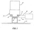
- FIG. 1 is a diagrammatic view of a machine vibration dampener in accordance with an embodiment of the present invention.
- Dampener 10 is coupled to source 12 of vibration.
- Source 12 may be any type of machinery or apparatus that generates a vibration for which dampening is desired.
- machine 12 may be a pump, a motor, a turbine, or any other mechanical system undergoing mechanical vibration.
- Dampener 10 couples machine 12 to floor 14 and is configured to translate at least some of the mechanical energy from source 12 into electricity.
- Dampener 10 includes an electromotive vibration generation module 16 that is coupled to source or load 18 via connection 20. Additionally, dampener 10 also includes a second generation module 22 that is preferably a piezoelectric generation module which is coupled to load or storage device 18 via line 24.
- a hybrid vibration-based generator includes a generator that generates electrical energy using at least two different types of generation.
- the example given above is a hybrid vibration-based generator by virtue of using both electromotive and piezoelectric based generation modules.
- a hybrid vibration-based generator would also include an electromotive generation module working in conjunction with a thermal generation module.
- the vibration-based electrical generation modules are embedded within dampener 10.
- dampener 10 is a piston-type vibration dampener. Dampener 10 is considered a piston-type dampener in that at least some of the mechanical vibration is channeled within cylindrical sidewall 26.
- FIG. 2 is a diagrammatic view of a bar-type vibration dampener in accordance with an embodiment of the present invention.
- the embodiment illustrated in FIG. 2 is somewhat similar to the embodiment illustrated in FIG. 1 , and like components are numbered similarly.
- bar-type dampener 30 is coupled to source 12 of vibration as well as floor 14.
- Dampener 30 includes, or has embedded therein, both electromotive generator 16, and piezoelectric generator 22.
- Electromotive generator 16 is coupled to load/storage device 18 via line 20.
- piezoelectric generator 22 is coupled to load/storage device 18 via line 24.
- FIGS. 1 and 2 illustrate piston-type and bar-type vibration dampeners, respectively, other vibration dampeners can be modified to include the hybrid electrical generation features described with respect to FIGS. 1 and 2 .
- FIG. 3 is a block diagram of a circuit used in conjunction with embodiments of the present invention.
- Circuit 40 includes, or is coupled to, each of electromotive generator 16 and piezoelectric generator 22.
- Generators 16, 22 are coupled to additive circuitry 42 which generates an output 44 that is the sum of all electrical energy generated by generator 16 and 22.
- Output 44 is provided as an input to step-up voltage converter 46, which increases the voltage of input 44 to a higher level.
- the output of voltage step-up converter 46 can be coupled directly to an output load or device, as indicated at label 48, or to storage device 50. Alternatively, the output of step-up voltage converter 46 can be provided- to both storage device 50 and output 48.
- Storage device 50 includes any component that is able to store electrical energy for some period of time. Suitable examples of storage device 50 include rechargeable batteries, capacitors, and the like.
- Electromotive generator 16 utilizes motion induced by the vibration in the presence of a permanent magnetic field to generate electricity. Accordingly, various structures may be used to form electromotive generator 16. However, one particular example will be provided later in the specification (with respect to FIG. 6 ).
- Piezoelectric generator .22 includes any device that operates in accordance with the piezoelectric effect wherein an electric charge is generated by a material in response to applied mechanical stress. A variety of materials that generate this effect are known, including the known PZT (lead zirconate titanate) ceramic. It is believed that using the hybrid-based generation can provide several hundred watts of electrical power that can be extracted from machine vibration, which energy would otherwise simply be wasted.
- embodiments of the present invention provide the ability to store up electrical energy and operate attached devices for short periods or bursts of time.
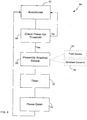
- FIG. 4 is a block diagram of such operation.
- Method 60 begins at block 62 where one or more vibration-based generators accumulate electrical energy.
- a threshold is checked to determine whether sufficient energy has been accumulated. This check can be done by examining the amount of energy stored in a storage device, such as a rechargeable battery and/or capacitor, or simply determining if a pre-selected amount of time has elapsed while energy is accumulated at block 62. If the threshold has not been reached, control returns to block 62 and energy continues to accumulate. However, if the threshold has been reached, control passes to block 66 where one or more attached devices are powered up. Examples of attached devices include field device 68 and wireless communication device 70. Typical field devices include pressure, temperature, level or flow transmitters or valves.
- the wireless communication device 70 may be part of a field device or a separate device for connection to a field device. However, any other suitable devices may be used.
- a timer is engaged to begin timing the initiation of the attached devices. Once timer 72 has determined that a selected amount of time has elapsed, control passes to block 74 where the attached device(s) are powered down. It should be noted that block 72 could be replaced with an alternate arrangement wherein the power available from the storage device (described with respect to FIG. 3 ) is monitored, and the device(s) are shutdown when the available power level drops below a certain threshold.
- Hybrid generation in accordance with embodiments of the present invention provides unique opportunities to perform diagnostics based upon the vibration itself. Accordingly, these devices are able to derive all of their operating electricity from the mechanical vibrations, while simultaneously providing diagnostic abilities relative to that vibration. This can be particularly important for industrial applications. For example, if the vibration stops or slows down, it may suggest that the industrial application has some sort of problem. Similarly, if the vibration frequency and/or amplitude increases significantly, it may also be indicative of a problem with the application.
- FIG. 5 is a flow diagram of a method of performing vibration-based diagnostics in accordance with an embodiment of the present invention.
- Method 80 begins at block 82 where initial conditions relative to the vibrational source are required. The acquisition of initial conditions can simply be performed when the device is first commissioned, when the vibration-machinery is started, or simply during programming or maintenance.
- control passes to block 84 where the generator determines, or otherwise measures, electromotive force from the electromotive generator.
- Control passes to block 86 where electromotive force from the piezoelectric generator is measured, or otherwise determined.
- at least one characteristic of the vibration is inferred from the measured quantities described with respect to blocks 84, 86.
- Exemplary vibration characteristics include frequency, amplitude, maximum amplitude, as well as changes to such quantities.
- the system determines whether the vibrational characteristics have changed relative to the initial conditions acquired at block 82. If such a change has not occurred, monitoring continues by returning to block 84. However, if such a change has occurred, control passes to block 92 and an alarm, or other suitable message is generated. Examples of suitable alarms/messages include audible or visual alarms locally .annunciated from the dampener, messages transmitted wirelessly through an attached device (such as wireless communicator 70). Such alarms/messages can alert an operator of the vibration-generating machinery that some condition has occurred that may merit an examination of the machinery.
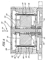
- FIG. 6 is a cross sectional view of a electromotive vibration-based generation device in accordance with an embodiment of the present invention.
- Device 100 may be embedded within a dampener, or simply attached to a vibration source to generate electricity based upon the vibration.
- device 100 includes top cover 102, housing 104, and bottom cover 106. Covers 102, 106 and housing 104 cooperate to form a chamber 108 inside.
- Device 100 includes a pair of permanent magnets, 110, 112 that are preferably donut-shaped and mounted concentrically with magnet 112 disposed within magnet 110.
- a voice coil 114 is disposed within annular space 116 between magnets 110, 112.
- the pair of ring-type permanent magnets, 110, 112 provides a high density transverse radial flux.
- Magnets 110, 112 are preferably formed of Neodymium Iron Boron (NdFeB). Such magnets can operate at degrees of 120°C and produce the most powerful magnetic properties per cubic centimeter currently known. However, any other suitable material, whether now known, or later developed, exhibiting permanent magnetic properties can be used.
- Voice coil 114 preferably has a first portion 118 and a second portion 120 that are separated from one another by ridge 122. Voice coil portions 118, 120 are preferably wound in opposite directions and are electrically cascaded together. First voice coil portion 118 cuts flux in the upper pair of poles between magnets 110, 112, while second voice coil portion 120 cuts flux in the lower pair of poles. Accordingly, the length of the wire within the voice coil portions and the poles are fully utilized.
- the voice coil portions 118, 120 can work in any orientation, and move and cut flux in both sides of magnets 110, 112 to produce voltages across the coil portions.
- Voice coil portions 118, 120 are suspended by a pair of flat springs 124, 126.
- Each flat spring 124, 126 preferably has a plurality (such as three) of curved cantilever beams with large aspect ratios to guarantee that the moving direction is relatively perpendicular to the spring surface.
- This orientation is that the assembly becomes compact, with a reduced part count. Additionally, large bi-directional deflections of the voice coil portions are possible. Further still, the arrangement reduces friction, wear and noise as well as provides self-alignment. It is believed that the assembly will be inexpensive to fabricate and easy to calibrate while providing less sensitivity to variations in assembly.
- Device 100 preferably includes flat spring tension screw 128 that engages internally threaded magnet retainer 130.
- Flat spring tension screw 128 bears against flat spring 132 and flat washer 134.
- a coil spring 136 bears against flat spring tension screw 128 that is disposed within magnet retainer 130. Electrical contacts relative to voice coil portions 118, 120 are preferably effected proximate the head of flat spring tension screw 128.
- Device 100 also includes .a slip nut 138 disposed around flat spring tension screw 128, which slip nut 138 bears against coil spring 136.
- spacers 140 and 142 are employed. However, other suitable spacers or arrangements can be used in accordance with embodiments of the present invention.
- Device 100 is expected to be relatively maintenance free and provide high reliability. Additionally, no external electrical power and wiring is required. Further, the device can be electrically coupled to any suitable electrical device, such as process control and monitoring field devices available from Rosemount, Inc., of Chanhassen, Minnesota. It is believed that device 100 can work in practically any orientation, however, it is preferred that the primary axis of the vibration be relatively aligned with axial axis 144 such that voice coil portions 118 and 120 derive maximum movement from the vibration. Using any suitable circuitry, various output levels can be provided, such outputs include 9 volt/4 mA, 5 volt/2 mA, and 3 volt/300 ⁇ A simultaneously for two seconds in a five minute cycle.
- any suitable electrical device such as process control and monitoring field devices available from Rosemount, Inc., of Chanhassen, Minnesota. It is believed that device 100 can work in practically any orientation, however, it is preferred that the primary axis of the vibration be relatively aligned with axial axis 144 such that voice coil portions 118 and 120 derive
- Peak DC output voltage for device 100 is believed to be on the order of 50 volts, 8 milliamps for an approximate ten minute cycle.
- Maximum power output is believed to be approximately 40 milliwatts, and has an energy density of 4.2 milliwatts per cubic inch at an input vibration of 45 Hz and an amplitude of 50 micrometers.
Landscapes
- Engineering & Computer Science (AREA)
- Chemical & Material Sciences (AREA)
- Combustion & Propulsion (AREA)
- Power Engineering (AREA)
- Mechanical Engineering (AREA)
- General Engineering & Computer Science (AREA)
- General Electrical Machinery Utilizing Piezoelectricity, Electrostriction Or Magnetostriction (AREA)
- Apparatuses For Generation Of Mechanical Vibrations (AREA)
- Mobile Radio Communication Systems (AREA)
Description
- Many industrial or business operations utilize electrical, mechanical, pneumatic, or some combination thereof, machinery. Examples of such machinery include electrical motors, turbines, et cetera. Typically, it is desirable to dampen, or otherwise attenuate, any vibrations generated by such machinery. Reducing the vibration of machinery generally reduces the noise of the machinery, as well as the mechanical wear that components disposed on or near the machinery undergo due to the acceleration caused by the vibration. Vibration dampeners in the form of pads or springs have been used in a variety of industries including, for example, heavy machinery, buildings, automotive vehicles, process industries, et cetera. These dampeners/pads/springs typically reduce, at least to some extent, the vibration, by transforming some of the mechanical motion's energy into the dampener and ultimately to thermal energy.
- While typically vibration dampening is considered essential for many situations, the mechanical energy translated into the dampener is essentially lost. Providing an improved device, structure or system that could couple to a source of mechanical vibration and generate useful energy would be highly desirable.
-
WO 2006/046937 discloses a vibration based generator according to the preamble of claim 1. - A hybrid vibration-based power generator according to claim 1 is provided. In another aspect, a device for generating electrical energy based is provided. The device includes a housing operably coupleable to a source of vibration. The housing defines a chamber inside. A first circular permanent magnet is located within the chamber and has an outer diameter. A ring-type permanent magnet is located around the first circular permanent magnet and defines an annular space therebetween. At least one voice coil portion is located in the annular space and is coupled to a flexure structure to allow the voice coil portion(s) to move within the flux of the permanent magnets in response to vibration.
-
-
FIG. 1 is a diagrammatic view of a machine vibration dampener in accordance with an embodiment of the present invention. -
FIG. 2 is a diagrammatic view of a bar-type vibration dampener in accordance with an embodiment of the present invention. -
FIG. 3 is a block diagram of a circuit used in conjunction with embodiments of the present invention. -
FIG. 4 is a method of storing electrical energy and operating at least one attached device for short period in accordance with an embodiment of the present invention. -
FIG. 5 is a flow diagram of a method of performing vibration-based diagnostics in accordance with an embodiment of the present invention. -
FIG. 6 is a cross sectional view of a electromotive vibration-based generation device in accordance with -an embodiment of the present invention. - Vibration is one of the great sources of renewable energy. Energy density generated from vibration can vary from 10 µW/cm3 to 800 µW/cm3 depending on the driving frequency, which ranges from the Hz to kHz range, and depending on amplitude/displacement of the vibrations. For example, consider a vibration providing an average energy density of 500 µW/cm3. A small pump of length 3 feet, width 3 feet, and height of 3 feet can produce 400 watts of electrical power. In process industries, and related other industries, heavy machinery and engines used by such industries are typically much heavier and occupy several thousand square feet of area. The vibration of such machines could produce significantly greater power.
- Embodiments of the present invention generally provide a device that couples to a source of mechanical vibration and transforms at least a portion of the mechanical vibration into useable electricity. In some embodiments, the device is itself a vibration dampener while in other embodiments, the device is simply attached to the source of vibration.
-
FIG. 1 is a diagrammatic view of a machine vibration dampener in accordance with an embodiment of the present invention.Dampener 10 is coupled tosource 12 of vibration.Source 12 may be any type of machinery or apparatus that generates a vibration for which dampening is desired. For example,machine 12 may be a pump, a motor, a turbine, or any other mechanical system undergoing mechanical vibration. Dampener 10couples machine 12 tofloor 14 and is configured to translate at least some of the mechanical energy fromsource 12 into electricity. Dampener 10 includes an electromotivevibration generation module 16 that is coupled to source or load 18 viaconnection 20. Additionally,dampener 10 also includes asecond generation module 22 that is preferably a piezoelectric generation module which is coupled to load orstorage device 18 vialine 24. As set forth herein, a hybrid vibration-based generator includes a generator that generates electrical energy using at least two different types of generation. The example given above is a hybrid vibration-based generator by virtue of using both electromotive and piezoelectric based generation modules. However, a hybrid vibration-based generator would also include an electromotive generation module working in conjunction with a thermal generation module. - In accordance with an embodiment of the present invention, the vibration-based electrical generation modules are embedded within
dampener 10. One advantage of such a hybrid approach is that for the electromotive generator, the generated power is directly proportional to the frequency of the oscillation. For piezoelectric-based generation, the generated power is directly proportional to the acceleration produced by the applied force, but is inversely proportional to the frequency. Using the hybrid approach, power can be generated for both high and low frequency applications. As illustrated inFIG. 1 ,dampener 10 is a piston-type vibration dampener.Dampener 10 is considered a piston-type dampener in that at least some of the mechanical vibration is channeled withincylindrical sidewall 26. -
FIG. 2 is a diagrammatic view of a bar-type vibration dampener in accordance with an embodiment of the present invention. The embodiment illustrated inFIG. 2 is somewhat similar to the embodiment illustrated inFIG. 1 , and like components are numbered similarly. As illustrated inFIG. 2 , bar-type dampener 30 is coupled tosource 12 of vibration as well asfloor 14.Dampener 30 includes, or has embedded therein, bothelectromotive generator 16, andpiezoelectric generator 22.Electromotive generator 16 is coupled to load/storage device 18 vialine 20. Similarly,piezoelectric generator 22 is coupled to load/storage device 18 vialine 24. - While
FIGS. 1 and2 illustrate piston-type and bar-type vibration dampeners, respectively, other vibration dampeners can be modified to include the hybrid electrical generation features described with respect toFIGS. 1 and2 . -
FIG. 3 is a block diagram of a circuit used in conjunction with embodiments of the present invention.Circuit 40 includes, or is coupled to, each ofelectromotive generator 16 andpiezoelectric generator 22.Generators additive circuitry 42 which generates anoutput 44 that is the sum of all electrical energy generated bygenerator Output 44 is provided as an input to step-upvoltage converter 46, which increases the voltage ofinput 44 to a higher level. The output of voltage step-up converter 46 can be coupled directly to an output load or device, as indicated atlabel 48, or tostorage device 50. Alternatively, the output of step-upvoltage converter 46 can be provided- to bothstorage device 50 andoutput 48.Storage device 50 includes any component that is able to store electrical energy for some period of time. Suitable examples ofstorage device 50 include rechargeable batteries, capacitors, and the like. -
Electromotive generator 16 utilizes motion induced by the vibration in the presence of a permanent magnetic field to generate electricity. Accordingly, various structures may be used to formelectromotive generator 16. However, one particular example will be provided later in the specification (with respect toFIG. 6 ). Piezoelectric generator .22 includes any device that operates in accordance with the piezoelectric effect wherein an electric charge is generated by a material in response to applied mechanical stress. A variety of materials that generate this effect are known, including the known PZT (lead zirconate titanate) ceramic. It is believed that using the hybrid-based generation can provide several hundred watts of electrical power that can be extracted from machine vibration, which energy would otherwise simply be wasted. - It is expressly contemplated that the maximum amount of power that may be derived, in some circumstances, from the mechanical vibration energy may be insufficient to power the attached device or devices in a steady-state fashion. Accordingly, embodiments of the present invention provide the ability to store up electrical energy and operate attached devices for short periods or bursts of time.
-
FIG. 4 is a block diagram of such operation.Method 60 begins atblock 62 where one or more vibration-based generators accumulate electrical energy. Atblock 64, a threshold is checked to determine whether sufficient energy has been accumulated. This check can be done by examining the amount of energy stored in a storage device, such as a rechargeable battery and/or capacitor, or simply determining if a pre-selected amount of time has elapsed while energy is accumulated atblock 62. If the threshold has not been reached, control returns to block 62 and energy continues to accumulate. However, if the threshold has been reached, control passes to block 66 where one or more attached devices are powered up. Examples of attached devices includefield device 68 andwireless communication device 70. Typical field devices include pressure, temperature, level or flow transmitters or valves. Thewireless communication device 70 may be part of a field device or a separate device for connection to a field device. However, any other suitable devices may be used. Atblock 72, a timer is engaged to begin timing the initiation of the attached devices. Oncetimer 72 has determined that a selected amount of time has elapsed, control passes to block 74 where the attached device(s) are powered down. It should be noted thatblock 72 could be replaced with an alternate arrangement wherein the power available from the storage device (described with respect toFIG. 3 ) is monitored, and the device(s) are shutdown when the available power level drops below a certain threshold. - Hybrid generation in accordance with embodiments of the present invention provides unique opportunities to perform diagnostics based upon the vibration itself. Accordingly, these devices are able to derive all of their operating electricity from the mechanical vibrations, while simultaneously providing diagnostic abilities relative to that vibration. This can be particularly important for industrial applications. For example, if the vibration stops or slows down, it may suggest that the industrial application has some sort of problem. Similarly, if the vibration frequency and/or amplitude increases significantly, it may also be indicative of a problem with the application.
-
FIG. 5 is a flow diagram of a method of performing vibration-based diagnostics in accordance with an embodiment of the present invention.Method 80 begins atblock 82 where initial conditions relative to the vibrational source are required. The acquisition of initial conditions can simply be performed when the device is first commissioned, when the vibration-machinery is started, or simply during programming or maintenance. Afterblock 82, control passes to block 84 where the generator determines, or otherwise measures, electromotive force from the electromotive generator. Control then passes to block 86 where electromotive force from the piezoelectric generator is measured, or otherwise determined. Atblock 88, at least one characteristic of the vibration is inferred from the measured quantities described with respect toblocks block 90, the system determines whether the vibrational characteristics have changed relative to the initial conditions acquired atblock 82. If such a change has not occurred, monitoring continues by returning to block 84. However, if such a change has occurred, control passes to block 92 and an alarm, or other suitable message is generated. Examples of suitable alarms/messages include audible or visual alarms locally .annunciated from the dampener, messages transmitted wirelessly through an attached device (such as wireless communicator 70). Such alarms/messages can alert an operator of the vibration-generating machinery that some condition has occurred that may merit an examination of the machinery. -
FIG. 6 is a cross sectional view of a electromotive vibration-based generation device in accordance with an embodiment of the present invention.Device 100 may be embedded within a dampener, or simply attached to a vibration source to generate electricity based upon the vibration. In this embodiment,device 100 includestop cover 102,housing 104, andbottom cover 106.Covers housing 104 cooperate to form achamber 108 inside.Device 100 includes a pair of permanent magnets, 110, 112 that are preferably donut-shaped and mounted concentrically withmagnet 112 disposed withinmagnet 110. Avoice coil 114 is disposed within annular space 116 betweenmagnets Magnets Voice coil 114 preferably has afirst portion 118 and asecond portion 120 that are separated from one another byridge 122.Voice coil portions voice coil portion 118 cuts flux in the upper pair of poles betweenmagnets voice coil portion 120 cuts flux in the lower pair of poles. Accordingly, the length of the wire within the voice coil portions and the poles are fully utilized. Thevoice coil portions magnets Voice coil portions flat springs flat spring -
Device 100 preferably includes flatspring tension screw 128 that engages internally threadedmagnet retainer 130. Flatspring tension screw 128 bears againstflat spring 132 andflat washer 134. By adjusting flatspring tension screw 128, the resonance frequency can be tuned to a specific frequency over a relatively wide range by changing the tension on the flat springs. Acoil spring 136 bears against flatspring tension screw 128 that is disposed withinmagnet retainer 130. Electrical contacts relative tovoice coil portions spring tension screw 128.Device 100 also includes .aslip nut 138 disposed around flatspring tension screw 128, which slipnut 138 bears againstcoil spring 136. In order to properly space the components withindevice 100,spacers 140 and 142 are employed. However, other suitable spacers or arrangements can be used in accordance with embodiments of the present invention. -
Device 100 is expected to be relatively maintenance free and provide high reliability. Additionally, no external electrical power and wiring is required. Further, the device can be electrically coupled to any suitable electrical device, such as process control and monitoring field devices available from Rosemount, Inc., of Chanhassen, Minnesota. It is believed thatdevice 100 can work in practically any orientation, however, it is preferred that the primary axis of the vibration be relatively aligned withaxial axis 144 such thatvoice coil portions device 100 is believed to be on the order of 50 volts, 8 milliamps for an approximate ten minute cycle. Maximum power output is believed to be approximately 40 milliwatts, and has an energy density of 4.2 milliwatts per cubic inch at an input vibration of 45 Hz and an amplitude of 50 micrometers. - Although the present invention has been described with reference to preferred embodiments, workers skilled in the art will recognize that changes may be made in form and detail without departing from the scope of the invention as defined by the claims.
Claims (17)
- A hybrid vibration-based power generator comprising:an electromotive power generation module (16);a power storage device (50) operably coupled to the electromotive power generation module (16);the hybrid vibration-based power generator characterised in that it further comprises a second power generation module (22), that converts power differently than the electromotive power generation module (16);the power storage device (50) is operably connected to the second power generation module (22); and in that the hybrid vibration-based power generator is embodied within a machine dampener (10).
- The hybrid vibration-based power generator of claim 1, wherein the hybrid vibration-based power generator is embodied within(i) a piston-type machine dampener or(ii) a bar-type machine dampener.
- The hybrid vibration-based power generator of claim 1 and further comprising an additive electrical circuit interposed between the power storage device (50) and the generation modules, wherein the additive electrical circuit is configured to provide an additive signal to the power storage device.
- The hybrid vibration-based power generator of claim 3, and further comprising a step-up voltage converter disposed between the additive electrical circuit and the power storage device.
- The hybrid vibration-based power generator of claim 1, wherein the hybrid vibration-based power generator is configured to provide an indication relative to a characteristic of vibration, wherein the indication is preferably a diagnostic indication relative to a source of vibration.
- The hybrid vibration-based power generator of claim 5, wherein the characteristic is (i) amplitude or (ii) frequency.
- The hybrid vibration-based power generator of claim 1, wherein the second generation module is (i) a piezoelectric generation module or (ii) a thermal generation module.
- A system for using energy from vibration, the system comprising:the hybrid vibration-based power generator according to any of claims 1 to 6, embodied within a machine vibration dampener, wherein:the electromotive power generation module is operably coupleable to a source of vibration;wherein the second power generation module isa piezoelectric power generation module operably coupleable to the source of vibration; andthe power storage device is operably coupled to the electromotive power generation module and the piezoelectric power generation module; further comprising a device operably coupled to and deriving power from the power storage device.
- The system of claim 8, wherein the device operably coupled to the power storage device is a field device, wherein the field device preferably provides a diagnostic indication relative to the source of vibration.
- The system of claim 8, wherein the device operably coupled to the power storage device is a wireless communication device, wherein the wireless communication device preferably provides a diagnostic indication relative to the source of vibration.
- The system of claim 8, wherein the device operably coupled to the power storage device is powered intermittently.
- A device for generating electrical energy based upon vibration comprising the hybrid vibration-based power generator according to any of claims 1 to 7, further comprising:a housing (104) operably coupleable to a source of vibration, the housing (104) defining a chamber therein;the electromotive power generator module comprising:a first circular permanent magnet (112) disposed within the chamber and having an outer diameter;a ring-type permanent magnet (110) disposed about the first circular permanent magnet and defining an annular space therebetween;at least one voice coil (114) portion disposed in the annular space;a flexure structure (124, 126) coupled to the at least one
voice coil portion and allowing the voice coil portion to move within the flux of the permanent magnets in response to vibration. - The device of claim 12, wherein the at least one voice coil portion includes a plurality of voice coil portions, wherein the plurality of voice coil portions are preferably electrically cascaded.
- The device of claim 13, wherein a first voice coil portion is wound in a first direction, and a second voice coil portion is wound in a direction that is opposite the first direction.
- The device of claim 12, wherein the flexure structure includes a plurality of flat springs, wherein each flat spring is preferably suspended by a plurality of cantilever beams.
- The device of claim 12, wherein the resonant frequency of the flexure structure is tunable, wherein the resonant frequency is preferable tunable by turning a screw that operably bears against at least one flat spring of the flexure structure.
- The device of claim 12, and further comprising a power storage device operably coupled to the at least one voice coil portion.
Applications Claiming Priority (2)
| Application Number | Priority Date | Filing Date | Title |
|---|---|---|---|
| US83756606P | 2006-08-14 | 2006-08-14 | |
| PCT/US2007/017926 WO2008021327A1 (en) | 2006-08-14 | 2007-08-13 | Vibration power generation |
Publications (2)
| Publication Number | Publication Date |
|---|---|
| EP2057375A1 EP2057375A1 (en) | 2009-05-13 |
| EP2057375B1 true EP2057375B1 (en) | 2018-10-10 |
Family
ID=38962843
Family Applications (1)
| Application Number | Title | Priority Date | Filing Date |
|---|---|---|---|
| EP07836784.4A Ceased EP2057375B1 (en) | 2006-08-14 | 2007-08-13 | Vibration power generation |
Country Status (7)
| Country | Link |
|---|---|
| US (1) | US7567013B2 (en) |
| EP (1) | EP2057375B1 (en) |
| JP (1) | JP5547481B2 (en) |
| CN (1) | CN101501330B (en) |
| CA (1) | CA2659839C (en) |
| RU (1) | RU2421629C2 (en) |
| WO (1) | WO2008021327A1 (en) |
Families Citing this family (60)
| Publication number | Priority date | Publication date | Assignee | Title |
|---|---|---|---|---|
| GB2446685B (en) * | 2007-11-27 | 2009-04-01 | Perpetuum Ltd | An electromechanical generator for converting mechanical vibrational energy into electrical energy |
| US7904210B2 (en) * | 2008-03-18 | 2011-03-08 | Visteon Global Technologies, Inc. | Vibration control system |
| GB2459269B (en) * | 2008-04-15 | 2010-09-29 | Perpetuum Ltd | An electromechanical generator for, and method of, converting mechanical vibrational energy into electrical energy |
| KR101805372B1 (en) * | 2008-11-10 | 2017-12-07 | 코넬 유니버시티 | Self-powered, piezo-surface acoustic wave apparatus and method |
| HUE031159T2 (en) * | 2009-04-09 | 2017-06-28 | Grieshaber Vega Kg | Energy-controlled data transmission of a field device |
| US8134279B2 (en) * | 2009-10-14 | 2012-03-13 | King Fahd University Of Petroleum And Minerals | Piezoelectric damping device |
| US8188622B1 (en) * | 2009-11-12 | 2012-05-29 | The United States Of America, As Represented By The Secretary Of The Navy | Tunable resonant frequency kinetic energy harvester |
| KR101081630B1 (en) * | 2009-11-20 | 2011-11-09 | 엘지이노텍 주식회사 | Voice coil motor |
| CN101739592B (en) * | 2009-12-31 | 2015-09-09 | 马宇尘 | The vibration measuring type electronic tag generated based on electric current and system |
| CN102208857A (en) * | 2010-03-29 | 2011-10-05 | 鸿富锦精密工业(深圳)有限公司 | Voice coil motor actuator and image capture apparatus |
| US8269399B2 (en) * | 2010-05-13 | 2012-09-18 | General Electric Company | Systems and apparatus for harvesting energy |
| US8836177B2 (en) * | 2010-07-30 | 2014-09-16 | Lg Innotek Co., Ltd. | Voice coil motor |
| JP2012135131A (en) * | 2010-12-22 | 2012-07-12 | Panasonic Corp | Power generation apparatus |
| US8410665B2 (en) | 2010-12-23 | 2013-04-02 | Taiwan Semiconductor Manufacturing Company, Ltd. | MEMS kinetic energy conversion |
| US9001626B1 (en) * | 2011-03-11 | 2015-04-07 | Rockwell Collins, Inc. | Piezoelectric acceleration timer |
| US8546964B2 (en) * | 2011-03-25 | 2013-10-01 | Tai-Her Yang | Reciprocal vibration type power generator equipped with a moving inner columnar magnetic block surrounded by at least one coil set, and a moving outer annular magnetic block that surrounds the at least one coil set |
| US8736086B2 (en) * | 2011-03-25 | 2014-05-27 | Tai-Her Yang | Reciprocal vibration type power generator equipped with inner columnar and outer annular magnetic members, a power storage device, a rectifying circuit, and a charging circuit |
| JP5808558B2 (en) * | 2011-03-31 | 2015-11-10 | 株式会社eスター | Vibration power generator |
| WO2015020887A2 (en) * | 2013-08-08 | 2015-02-12 | Northeastern University | Improvements for a non-rotating wind energy generator |
| US9222465B2 (en) | 2011-04-15 | 2015-12-29 | Northeastern University | Non-rotating wind energy generator |
| CN104221110B (en) | 2011-07-08 | 2019-04-05 | 快帽系统公司 | High temperature energy storage device |
| US9558894B2 (en) | 2011-07-08 | 2017-01-31 | Fastcap Systems Corporation | Advanced electrolyte systems and their use in energy storage devices |
| WO2013028092A1 (en) * | 2011-08-24 | 2013-02-28 | Dostiiari Nasir Nadir Ogly | Piezo-electric source of electrical energy for vehicles |
| CN104024573B (en) | 2011-11-03 | 2018-05-15 | 快帽系统公司 | Production logging instrument |
| CN103208899B (en) * | 2012-01-16 | 2016-02-17 | 曾胜克 | power generation device |
| GB201207987D0 (en) * | 2012-05-04 | 2012-06-20 | Imp Innovations Ltd | Power generation device |
| CN102969864B (en) * | 2012-10-26 | 2016-06-08 | 安徽工程大学 | A kind of TRT utilizing straight reciprocating motion to generate electricity |
| TWI504806B (en) * | 2012-11-09 | 2015-10-21 | Ching Wu Wang | High efficiency sound panel and its energy storage system |
| GB2518918B (en) * | 2012-11-13 | 2016-07-06 | Perpetuum Ltd | An electromechanical generator for, and method of, converting mechanical vibrational energy into electrical energy |
| CN102979851B (en) * | 2012-12-13 | 2014-09-17 | 浙江师范大学 | Wafer-type piezoelectric hydraulic damper based on curve surface spacing |
| MA36246B1 (en) * | 2013-09-13 | 2015-10-30 | Saady Mohamed Es | An apparatus that produces electrical energy from agitation or through receivers. |
| US10872737B2 (en) | 2013-10-09 | 2020-12-22 | Fastcap Systems Corporation | Advanced electrolytes for high temperature energy storage device |
| EP2860405B1 (en) * | 2013-10-14 | 2016-05-25 | Techspace Aero S.A. | Piezoelectric damper system for axial turbomachine rotor |
| EP3084481B8 (en) | 2013-12-20 | 2024-01-03 | Fastcap Systems Corporation | Electromagnetic telemetry device |
| CN104976083A (en) * | 2014-04-03 | 2015-10-14 | 朱介北 | Automatic power generation device used when four-wheel electric vehicle runs |
| CN104201857B (en) * | 2014-08-22 | 2017-02-15 | 重庆交通大学 | Vibration power generation device |
| US20160089298A1 (en) | 2014-09-29 | 2016-03-31 | Otolith Sound Inc | Device for Mitigating Motion Sickness and Other Responses to Inconsistent Sensory Information |
| KR102469677B1 (en) | 2015-01-27 | 2022-11-22 | 패스트캡 시스템즈 코포레이션 | Wide temperature range ultracapacitors |
| CN105134524A (en) * | 2015-09-02 | 2015-12-09 | 北京印刷学院 | Gas energy storage and piezoelectric deformation damping and power generation device for urban railway train |
| CN105201764A (en) * | 2015-09-02 | 2015-12-30 | 北京印刷学院 | Mass energy conversion device adopting gas energy storage and double-cylinder reciprocation electromagnetic transduction and applied to railway remote monitoring |
| CN105201763B (en) * | 2015-09-02 | 2018-07-24 | 北京印刷学院 | Axial symmetry elastic deformation energy storage piezoelectric transduction city underground train shock-absorbing generation device |
| CN105201766A (en) * | 2015-09-02 | 2015-12-30 | 北京印刷学院 | Mass energy conversion device adopting gas energy storage and double-cylinder reciprocation vibrating piezoelectric transduction and applied to railway remote monitoring |
| CN105201765A (en) * | 2015-09-02 | 2015-12-30 | 北京印刷学院 | Urban subway train damping generation device adopting electro-mechanical transformation of resonance energy storage |
| CN105114271A (en) * | 2015-09-02 | 2015-12-02 | 北京印刷学院 | Axisymmetric gas energy-storage electromagnetic transformation city subway train damping generating apparatus |
| CN105141181B (en) * | 2015-10-08 | 2018-02-02 | 北京理工大学 | A kind of piezoelectricity electromagnetism combined type energy accumulator |
| CN105932856A (en) * | 2016-06-28 | 2016-09-07 | 西安陆洲智能传感技术有限公司 | High-output vibrating magnetoelectric generator |
| US10398897B2 (en) * | 2016-11-14 | 2019-09-03 | Otolith Sound Inc. | Systems, devices, and methods for treating vestibular conditions |
| US11284205B2 (en) | 2016-11-14 | 2022-03-22 | Otolith Sound Inc. | Systems, devices, and methods for treating vestibular conditions |
| WO2018102652A1 (en) | 2016-12-02 | 2018-06-07 | Fastcap Systems Corporation | Composite electrode |
| RU2637156C1 (en) * | 2016-12-14 | 2017-11-30 | Федеральное государственное бюджетное учреждение науки Институт проблем машиноведения Российской академии наук (ИПМаш РАН) | Method of energy generation in which harmful support vibration is used and simultaneously partially dampened (versions) |
| RU187037U1 (en) * | 2017-04-13 | 2019-02-14 | Общество с ограниченной ответственностью Научно-исследовательский институт "Уралмет" | Device for generating electric energy using mechanical vibrations of the rotor of a wind power plant |
| KR20190000950A (en) * | 2017-06-23 | 2019-01-04 | 주식회사 코아칩스 | Vibration energy harvesting device capable of adjusting operating frequency |
| CN108847737A (en) * | 2018-06-15 | 2018-11-20 | 哈尔滨工程大学 | A kind of Wave energy acquisition device for sonar buoy power supply |
| WO2020079616A1 (en) * | 2018-10-16 | 2020-04-23 | Thomas Nikita Krupenkin | Method and apparatus for mechanical energy harvesting using variable inductance magnetic flux switch |
| DE102019200049A1 (en) * | 2019-01-04 | 2020-07-09 | Aktiebolaget Skf | A SUSPENSION ASSEMBLY |
| DE102019128612A1 (en) * | 2019-10-23 | 2021-04-29 | Saurer Spinning Solutions Gmbh & Co. Kg | Textile machine |
| DE102020101177A1 (en) * | 2020-01-20 | 2021-07-22 | Sisto Armaturen S.A. | System for operating a pneumatic device |
| CN113279204B (en) * | 2020-02-18 | 2024-07-23 | 佛山海尔滚筒洗衣机有限公司 | Clothes processing equipment |
| CN114427586B (en) * | 2022-01-20 | 2022-10-14 | 中南大学 | A dynamic load energy capture device for railway subgrade based on carbon neutrality concept |
| WO2025257843A1 (en) * | 2024-06-12 | 2025-12-18 | Singh Deepinder Jeet | A device for producing electric current from vibrations |
Family Cites Families (57)
| Publication number | Priority date | Publication date | Assignee | Title |
|---|---|---|---|---|
| US2895063A (en) | 1951-01-19 | 1959-07-14 | George V Morris | Air driven reed electric generator |
| US3539841A (en) * | 1968-02-21 | 1970-11-10 | Motorola Inc | Piezoelectric voltage generator |
| USRE31217E (en) | 1968-05-27 | 1983-04-26 | Neptune Eastech, Inc. | Bluff body flowmeter |
| US3568704A (en) | 1969-08-27 | 1971-03-09 | Us Navy | Fluidic generator with velocity discrimination |
| US3663845A (en) | 1971-02-18 | 1972-05-16 | Us Navy | Fluidic generator |
| US3798475A (en) | 1972-03-27 | 1974-03-19 | Us Army | Square wedge fluidic generator for electrical and mechanical outputs |
| US4005319A (en) | 1973-04-23 | 1977-01-25 | Saab-Scania Aktiebolag | Piezoelectric generator operated by fluid flow |
| US3878716A (en) | 1973-12-19 | 1975-04-22 | Hokushin Electric Works | Karman vortex shedder |
| US4148215A (en) | 1978-06-19 | 1979-04-10 | General Signal Corporation | Apparatus for making rheological measurements |
| GB2111680A (en) | 1981-11-03 | 1983-07-06 | Itt Ind Ltd | Vortex flowmeter |
| DE3277825D1 (en) | 1981-11-24 | 1988-01-21 | Shell Int Research | Means for generating electric energy in a borehole during drilling thereof |
| GB2119514B (en) | 1982-04-22 | 1985-06-26 | Marconi Co Ltd | Vortex-shedding flowmeters |
| GB2121185A (en) | 1982-05-11 | 1983-12-14 | John Michael Wood | Flow sensor for breath and other gas analysers |
| GB2142725A (en) | 1983-06-21 | 1985-01-23 | United Gas Industries Ltd | Fluid flow meter |
| JPS6489947A (en) * | 1987-09-30 | 1989-04-05 | Aisin Seiki | Generating set for vehicle |
| RU2037255C1 (en) * | 1992-09-10 | 1995-06-09 | Борис Тимофеевич Тучин | Electric power generator |
| CN1075601C (en) * | 1994-10-26 | 2001-11-28 | 张瑞庆 | Vibration engine |
| US5707215A (en) * | 1994-11-14 | 1998-01-13 | Hughes Aircraft Company | Tuned resonant oscillating mass inflation pump and method of extracting electrical energy therefrom |
| FR2727583B1 (en) | 1994-11-29 | 1996-12-20 | Commissariat Energie Atomique | ELECTROSTATIC MOTOR AND ITS MANUFACTURING METHOD |
| JPH09323109A (en) * | 1996-06-05 | 1997-12-16 | Hitachi Ltd | Rolling mill abnormality determination control device and method |
| US6058787A (en) * | 1996-06-21 | 2000-05-09 | Hughes Technology Group L.L.C | Mass flow measuring device |
| DE29618105U1 (en) * | 1996-10-18 | 1997-02-20 | TR Elektronic GmbH, 84533 Haiming | Energy generating device as a battery or accumulator replacement |
| JPH1118445A (en) * | 1997-06-19 | 1999-01-22 | Daewoo Electron Co Ltd | Piezoelectric type generator and manufacture thereof |
| JP2876530B1 (en) | 1998-02-24 | 1999-03-31 | 東京工業大学長 | Ultra-small element having means for repairing fixed movable part and method of manufacturing the same |
| JPH11341837A (en) * | 1998-05-28 | 1999-12-10 | Nippon Soken Inc | Piezoelectric power supply |
| US6127812A (en) | 1999-02-16 | 2000-10-03 | General Electric Company | Integrated environmental energy extractor |
| DE19929341A1 (en) | 1999-06-26 | 2000-12-28 | Abb Research Ltd | Arrangement for wireless electric power supply of number of sensors and/or actuators has component for converting acceleration into electrical energy integrated into sensors/actuators |
| US6628019B2 (en) | 1999-07-21 | 2003-09-30 | Westinghouse Air Brake Technologies Corporation | High efficiency pneumatically driven electric power generator |
| US6470755B1 (en) | 1999-08-05 | 2002-10-29 | Dieterich Standard, Inc. | Noise reducing differential pressure measurement probe |
| JP2001086723A (en) * | 1999-09-14 | 2001-03-30 | Mitsubishi Heavy Ind Ltd | Oscillation-absorbing type generator |
| US6315813B1 (en) | 1999-11-18 | 2001-11-13 | Northland Energy Corporation | Method of treating pressurized drilling fluid returns from a well |
| WO2001061281A2 (en) | 2000-02-15 | 2001-08-23 | Young Alan M | Method and apparatus using magnus effect to measure mass flow rate |
| US6703768B2 (en) | 2000-09-27 | 2004-03-09 | Citizen Watch Co., Ltd. | Piezoelectric generator and mounting structure therefor |
| WO2002079703A2 (en) | 2001-02-13 | 2002-10-10 | Technology Applications, Inc. | Miniature reciprocating heat pumps and engines |
| DE10125059C5 (en) * | 2001-05-22 | 2016-07-21 | Enocean Gmbh | Inductive voltage generator |
| US6713942B2 (en) | 2001-05-23 | 2004-03-30 | Purdue Research Foundation | Piezoelectric device with feedback sensor |
| US6593666B1 (en) | 2001-06-20 | 2003-07-15 | Ambient Systems, Inc. | Energy conversion systems using nanometer scale assemblies and methods for using same |
| DE10247387A1 (en) * | 2001-10-15 | 2003-09-11 | Karl Ludwig Holder | Power station has turbine or piston engine, and pressure build-up devices with heat exchangers filled with carbon dioxide for converting thermal to electrical energy with generator |
| NO20016398D0 (en) | 2001-12-27 | 2001-12-27 | Abb Research Ltd | Mini-power converter I |
| NO20016399D0 (en) | 2001-12-27 | 2001-12-27 | Abb Research Ltd | Mini-power converter II |
| US6737789B2 (en) * | 2002-01-18 | 2004-05-18 | Leon J. Radziemski | Force activated, piezoelectric, electricity generation, storage, conditioning and supply apparatus and methods |
| DE10205531B4 (en) | 2002-02-11 | 2004-05-27 | Kai Wissner | Device for extracting energy from a flowing fluid |
| US7035773B2 (en) * | 2002-03-06 | 2006-04-25 | Fisher-Rosemount Systems, Inc. | Appendable system and devices for data acquisition, analysis and control |
| US7256505B2 (en) * | 2003-03-05 | 2007-08-14 | Microstrain, Inc. | Shaft mounted energy harvesting for wireless sensor operation and data transmission |
| SE524369C2 (en) * | 2002-08-09 | 2004-07-27 | Mecel Ab | Method for increasing efficiency when using an engine and system unit |
| JP2004100840A (en) * | 2002-09-10 | 2004-04-02 | Takenaka Komuten Co Ltd | Vibration source support device |
| US6975043B2 (en) | 2003-12-22 | 2005-12-13 | Rosemount, Inc. | Pressurized gas to electrical energy conversion for low-power field devices |
| JP2005247129A (en) * | 2004-03-04 | 2005-09-15 | Toyota Motor Corp | Tire abnormality detection device |
| US8538560B2 (en) * | 2004-04-29 | 2013-09-17 | Rosemount Inc. | Wireless power and communication unit for process field devices |
| JP2005348546A (en) * | 2004-06-04 | 2005-12-15 | Yoshifumi Morita | Oscillating generator |
| FR2872868A1 (en) * | 2004-07-06 | 2006-01-13 | Commissariat Energie Atomique | ENERGY RECOVERY DEVICE |
| WO2006010203A1 (en) * | 2004-07-28 | 2006-02-02 | Kinergi Pty Ltd | Motion activated power source |
| EP1803168A4 (en) * | 2004-10-21 | 2009-05-20 | Michelin Soc Tech | MINIATURIZED PIEZOELECTRIC COLLECTOR OF VIBRATION ENERGY |
| WO2006046937A1 (en) | 2004-10-21 | 2006-05-04 | Societe De Technologie Michelin | Energy harvester with adjustable resonant frequency |
| CN1328836C (en) * | 2004-11-22 | 2007-07-25 | 西安交通大学 | Rail vehicle vibrating energy piezoelectric power generating method and system thereof |
| CN100336281C (en) * | 2004-11-22 | 2007-09-05 | 西安交通大学 | Rolling stock rail vibration energy piezoelectric power generating method and system thereof |
| US8159090B2 (en) * | 2006-09-01 | 2012-04-17 | Powercast Corporation | Hybrid power harvesting and method |
-
2007
- 2007-08-13 RU RU2009109195/06A patent/RU2421629C2/en not_active IP Right Cessation
- 2007-08-13 EP EP07836784.4A patent/EP2057375B1/en not_active Ceased
- 2007-08-13 US US11/891,855 patent/US7567013B2/en active Active
- 2007-08-13 WO PCT/US2007/017926 patent/WO2008021327A1/en not_active Ceased
- 2007-08-13 CA CA2659839A patent/CA2659839C/en not_active Expired - Fee Related
- 2007-08-13 CN CN200780030291.7A patent/CN101501330B/en not_active Expired - Fee Related
- 2007-08-13 JP JP2009524653A patent/JP5547481B2/en not_active Expired - Fee Related
Non-Patent Citations (1)
| Title |
|---|
| None * |
Also Published As
| Publication number | Publication date |
|---|---|
| CA2659839A1 (en) | 2008-02-21 |
| EP2057375A1 (en) | 2009-05-13 |
| RU2421629C2 (en) | 2011-06-20 |
| CN101501330B (en) | 2013-05-29 |
| US7567013B2 (en) | 2009-07-28 |
| JP5547481B2 (en) | 2014-07-16 |
| JP2010500866A (en) | 2010-01-07 |
| US20080036307A1 (en) | 2008-02-14 |
| CN101501330A (en) | 2009-08-05 |
| WO2008021327A1 (en) | 2008-02-21 |
| RU2009109195A (en) | 2010-09-27 |
| CA2659839C (en) | 2012-03-20 |
Similar Documents
| Publication | Publication Date | Title |
|---|---|---|
| US7567013B2 (en) | Vibration power generation | |
| JP2010500866A5 (en) | ||
| EP2677656B1 (en) | Tunable vibration energy harvester and energy harvesting method | |
| EP1997210B1 (en) | An electromechanical generator for, and method of, converting mechanical vibrational energy into electrical energy | |
| KR100817319B1 (en) | Power generator of mobile device and self-generation system having same | |
| US20110095648A1 (en) | Nonlinear oscillator for vibration energy harvesting | |
| JP2000222668A (en) | Self-output type wireless converter, failure detection apparatus and method | |
| Zhu et al. | Vibration energy harvesting in automobiles to power wireless sensors | |
| EP1938395A2 (en) | Energy harvesting using frequency rectification | |
| EP3761254B1 (en) | Energy harvester and engine monitoring system using same | |
| Seo et al. | Vibration energy harvesting technology for smart tire monitoring | |
| KR101544056B1 (en) | Self-powered floor noise/vibration monitoring device | |
| KR101553911B1 (en) | Energy harvester | |
| Gao et al. | Vibration-based energy extraction for sensor powering: design, analysis, and experimental evaluation | |
| WO2007063271A2 (en) | Vibration sensor | |
| KR101591444B1 (en) | Energy harvester | |
| KR101539340B1 (en) | Energy harvester and wireless sensor device including the same | |
| KR101553912B1 (en) | Energy harvester | |
| CN112117934A (en) | Power generation device for absorbing vibration energy | |
| KR20150133602A (en) | Energy harvester | |
| Kumagai et al. | Development of multi-axis vibration power generation device for automobiles | |
| NZ611441B (en) | Tunable vibration energy harvester and method |
Legal Events
| Date | Code | Title | Description |
|---|---|---|---|
| PUAI | Public reference made under article 153(3) epc to a published international application that has entered the european phase |
Free format text: ORIGINAL CODE: 0009012 |
|
| 17P | Request for examination filed |
Effective date: 20090311 |
|
| AK | Designated contracting states |
Kind code of ref document: A1 Designated state(s): AT BE BG CH CY CZ DE DK EE ES FI FR GB GR HU IE IS IT LI LT LU LV MC MT NL PL PT RO SE SI SK TR |
|
| AX | Request for extension of the european patent |
Extension state: AL BA HR MK RS |
|
| RBV | Designated contracting states (corrected) |
Designated state(s): CH DE LI |
|
| DAX | Request for extension of the european patent (deleted) | ||
| 17Q | First examination report despatched |
Effective date: 20130405 |
|
| RAP1 | Party data changed (applicant data changed or rights of an application transferred) |
Owner name: ROSEMOUNT INC. |
|
| GRAP | Despatch of communication of intention to grant a patent |
Free format text: ORIGINAL CODE: EPIDOSNIGR1 |
|
| INTG | Intention to grant announced |
Effective date: 20180420 |
|
| GRAS | Grant fee paid |
Free format text: ORIGINAL CODE: EPIDOSNIGR3 |
|
| GRAA | (expected) grant |
Free format text: ORIGINAL CODE: 0009210 |
|
| AK | Designated contracting states |
Kind code of ref document: B1 Designated state(s): CH DE LI |
|
| REG | Reference to a national code |
Ref country code: CH Ref legal event code: EP |
|
| REG | Reference to a national code |
Ref country code: DE Ref legal event code: R096 Ref document number: 602007056471 Country of ref document: DE |
|
| REG | Reference to a national code |
Ref country code: CH Ref legal event code: NV Representative=s name: VOSSIUS AND PARTNER PATENTANWAELTE RECHTSANWAE, CH |
|
| REG | Reference to a national code |
Ref country code: DE Ref legal event code: R097 Ref document number: 602007056471 Country of ref document: DE |
|
| PLBE | No opposition filed within time limit |
Free format text: ORIGINAL CODE: 0009261 |
|
| STAA | Information on the status of an ep patent application or granted ep patent |
Free format text: STATUS: NO OPPOSITION FILED WITHIN TIME LIMIT |
|
| 26N | No opposition filed |
Effective date: 20190711 |
|
| PGFP | Annual fee paid to national office [announced via postgrant information from national office to epo] |
Ref country code: CH Payment date: 20190903 Year of fee payment: 13 |
|
| REG | Reference to a national code |
Ref country code: CH Ref legal event code: PL |
|
| PG25 | Lapsed in a contracting state [announced via postgrant information from national office to epo] |
Ref country code: LI Free format text: LAPSE BECAUSE OF NON-PAYMENT OF DUE FEES Effective date: 20200831 Ref country code: CH Free format text: LAPSE BECAUSE OF NON-PAYMENT OF DUE FEES Effective date: 20200831 |
|
| PGFP | Annual fee paid to national office [announced via postgrant information from national office to epo] |
Ref country code: DE Payment date: 20210720 Year of fee payment: 15 |
|
| REG | Reference to a national code |
Ref country code: DE Ref legal event code: R119 Ref document number: 602007056471 Country of ref document: DE |
|
| PG25 | Lapsed in a contracting state [announced via postgrant information from national office to epo] |
Ref country code: DE Free format text: LAPSE BECAUSE OF NON-PAYMENT OF DUE FEES Effective date: 20230301 |