EP2056911B1 - Apparatus for distinguishing between closed and open respiratory airway apneas by complex admittance values - Google Patents
Apparatus for distinguishing between closed and open respiratory airway apneas by complex admittance values Download PDFInfo
- Publication number
- EP2056911B1 EP2056911B1 EP07800218.5A EP07800218A EP2056911B1 EP 2056911 B1 EP2056911 B1 EP 2056911B1 EP 07800218 A EP07800218 A EP 07800218A EP 2056911 B1 EP2056911 B1 EP 2056911B1
- Authority
- EP
- European Patent Office
- Prior art keywords
- patient
- flow
- pressure
- admittance
- mask
- Prior art date
- Legal status (The legal status is an assumption and is not a legal conclusion. Google has not performed a legal analysis and makes no representation as to the accuracy of the status listed.)
- Active
Links
- 208000008784 apnea Diseases 0.000 title claims description 51
- 230000000241 respiratory effect Effects 0.000 title claims description 28
- 230000029058 respiratory gaseous exchange Effects 0.000 claims description 14
- 230000001939 inductive effect Effects 0.000 claims description 4
- 238000000034 method Methods 0.000 description 31
- 238000004364 calculation method Methods 0.000 description 18
- 230000003534 oscillatory effect Effects 0.000 description 12
- 230000010355 oscillation Effects 0.000 description 10
- 238000004422 calculation algorithm Methods 0.000 description 8
- 230000001965 increasing effect Effects 0.000 description 7
- 238000000926 separation method Methods 0.000 description 7
- 230000000694 effects Effects 0.000 description 6
- 230000007958 sleep Effects 0.000 description 6
- 230000006872 improvement Effects 0.000 description 5
- 238000005259 measurement Methods 0.000 description 5
- 208000003417 Central Sleep Apnea Diseases 0.000 description 4
- 230000008901 benefit Effects 0.000 description 4
- 230000003247 decreasing effect Effects 0.000 description 4
- 238000010586 diagram Methods 0.000 description 4
- 239000007789 gas Substances 0.000 description 4
- 206010041235 Snoring Diseases 0.000 description 3
- 208000037265 diseases, disorders, signs and symptoms Diseases 0.000 description 3
- 208000035475 disorder Diseases 0.000 description 3
- 210000004072 lung Anatomy 0.000 description 3
- 230000000414 obstructive effect Effects 0.000 description 3
- 208000001797 obstructive sleep apnea Diseases 0.000 description 3
- 101000836150 Homo sapiens Transforming acidic coiled-coil-containing protein 3 Proteins 0.000 description 2
- 206010021079 Hypopnoea Diseases 0.000 description 2
- 102100027048 Transforming acidic coiled-coil-containing protein 3 Human genes 0.000 description 2
- 230000002159 abnormal effect Effects 0.000 description 2
- 238000013459 approach Methods 0.000 description 2
- 239000008280 blood Substances 0.000 description 2
- 210000004369 blood Anatomy 0.000 description 2
- 238000001514 detection method Methods 0.000 description 2
- 230000003434 inspiratory effect Effects 0.000 description 2
- 230000003993 interaction Effects 0.000 description 2
- 238000006213 oxygenation reaction Methods 0.000 description 2
- 238000012545 processing Methods 0.000 description 2
- 230000002829 reductive effect Effects 0.000 description 2
- 210000002345 respiratory system Anatomy 0.000 description 2
- 201000002859 sleep apnea Diseases 0.000 description 2
- 230000003068 static effect Effects 0.000 description 2
- 208000011580 syndromic disease Diseases 0.000 description 2
- 238000009423 ventilation Methods 0.000 description 2
- 208000007590 Disorders of Excessive Somnolence Diseases 0.000 description 1
- 206010062519 Poor quality sleep Diseases 0.000 description 1
- 208000010340 Sleep Deprivation Diseases 0.000 description 1
- 206010041349 Somnolence Diseases 0.000 description 1
- 206010063968 Upper airway resistance syndrome Diseases 0.000 description 1
- 230000003187 abdominal effect Effects 0.000 description 1
- 230000005856 abnormality Effects 0.000 description 1
- 230000001133 acceleration Effects 0.000 description 1
- 230000002411 adverse Effects 0.000 description 1
- QVGXLLKOCUKJST-UHFFFAOYSA-N atomic oxygen Chemical compound [O] QVGXLLKOCUKJST-UHFFFAOYSA-N 0.000 description 1
- 230000006399 behavior Effects 0.000 description 1
- 238000009530 blood pressure measurement Methods 0.000 description 1
- 210000000621 bronchi Anatomy 0.000 description 1
- 230000000747 cardiac effect Effects 0.000 description 1
- 230000008859 change Effects 0.000 description 1
- 210000000038 chest Anatomy 0.000 description 1
- 208000020020 complex sleep apnea Diseases 0.000 description 1
- 230000001934 delay Effects 0.000 description 1
- 238000009795 derivation Methods 0.000 description 1
- 238000003745 diagnosis Methods 0.000 description 1
- 230000004069 differentiation Effects 0.000 description 1
- 230000002526 effect on cardiovascular system Effects 0.000 description 1
- 230000002124 endocrine Effects 0.000 description 1
- 238000001914 filtration Methods 0.000 description 1
- 239000012530 fluid Substances 0.000 description 1
- 208000019622 heart disease Diseases 0.000 description 1
- 201000006646 mixed sleep apnea Diseases 0.000 description 1
- 239000001301 oxygen Substances 0.000 description 1
- 229910052760 oxygen Inorganic materials 0.000 description 1
- 230000010363 phase shift Effects 0.000 description 1
- 230000009467 reduction Effects 0.000 description 1
- 210000003019 respiratory muscle Anatomy 0.000 description 1
- 238000005070 sampling Methods 0.000 description 1
- 238000004088 simulation Methods 0.000 description 1
- 210000001584 soft palate Anatomy 0.000 description 1
- 238000010561 standard procedure Methods 0.000 description 1
- 210000003437 trachea Anatomy 0.000 description 1
- 230000036642 wellbeing Effects 0.000 description 1
Images


Classifications
-
- A—HUMAN NECESSITIES
- A61—MEDICAL OR VETERINARY SCIENCE; HYGIENE
- A61M—DEVICES FOR INTRODUCING MEDIA INTO, OR ONTO, THE BODY; DEVICES FOR TRANSDUCING BODY MEDIA OR FOR TAKING MEDIA FROM THE BODY; DEVICES FOR PRODUCING OR ENDING SLEEP OR STUPOR
- A61M16/00—Devices for influencing the respiratory system of patients by gas treatment, e.g. mouth-to-mouth respiration; Tracheal tubes
-
- A—HUMAN NECESSITIES
- A61—MEDICAL OR VETERINARY SCIENCE; HYGIENE
- A61B—DIAGNOSIS; SURGERY; IDENTIFICATION
- A61B5/00—Measuring for diagnostic purposes; Identification of persons
- A61B5/08—Detecting, measuring or recording devices for evaluating the respiratory organs
- A61B5/0826—Detecting or evaluating apnoea events
-
- A—HUMAN NECESSITIES
- A61—MEDICAL OR VETERINARY SCIENCE; HYGIENE
- A61B—DIAGNOSIS; SURGERY; IDENTIFICATION
- A61B5/00—Measuring for diagnostic purposes; Identification of persons
- A61B5/08—Detecting, measuring or recording devices for evaluating the respiratory organs
- A61B5/085—Measuring impedance of respiratory organs or lung elasticity
-
- A—HUMAN NECESSITIES
- A61—MEDICAL OR VETERINARY SCIENCE; HYGIENE
- A61B—DIAGNOSIS; SURGERY; IDENTIFICATION
- A61B5/00—Measuring for diagnostic purposes; Identification of persons
- A61B5/08—Detecting, measuring or recording devices for evaluating the respiratory organs
- A61B5/087—Measuring breath flow
-
- A—HUMAN NECESSITIES
- A61—MEDICAL OR VETERINARY SCIENCE; HYGIENE
- A61B—DIAGNOSIS; SURGERY; IDENTIFICATION
- A61B5/00—Measuring for diagnostic purposes; Identification of persons
- A61B5/48—Other medical applications
- A61B5/4806—Sleep evaluation
- A61B5/4818—Sleep apnoea
-
- A—HUMAN NECESSITIES
- A61—MEDICAL OR VETERINARY SCIENCE; HYGIENE
- A61M—DEVICES FOR INTRODUCING MEDIA INTO, OR ONTO, THE BODY; DEVICES FOR TRANSDUCING BODY MEDIA OR FOR TAKING MEDIA FROM THE BODY; DEVICES FOR PRODUCING OR ENDING SLEEP OR STUPOR
- A61M16/00—Devices for influencing the respiratory system of patients by gas treatment, e.g. mouth-to-mouth respiration; Tracheal tubes
- A61M16/0003—Accessories therefor, e.g. sensors, vibrators, negative pressure
-
- A—HUMAN NECESSITIES
- A61—MEDICAL OR VETERINARY SCIENCE; HYGIENE
- A61M—DEVICES FOR INTRODUCING MEDIA INTO, OR ONTO, THE BODY; DEVICES FOR TRANSDUCING BODY MEDIA OR FOR TAKING MEDIA FROM THE BODY; DEVICES FOR PRODUCING OR ENDING SLEEP OR STUPOR
- A61M16/00—Devices for influencing the respiratory system of patients by gas treatment, e.g. mouth-to-mouth respiration; Tracheal tubes
- A61M16/0057—Pumps therefor
- A61M16/0066—Blowers or centrifugal pumps
- A61M16/0069—Blowers or centrifugal pumps the speed thereof being controlled by respiratory parameters, e.g. by inhalation
-
- A—HUMAN NECESSITIES
- A61—MEDICAL OR VETERINARY SCIENCE; HYGIENE
- A61M—DEVICES FOR INTRODUCING MEDIA INTO, OR ONTO, THE BODY; DEVICES FOR TRANSDUCING BODY MEDIA OR FOR TAKING MEDIA FROM THE BODY; DEVICES FOR PRODUCING OR ENDING SLEEP OR STUPOR
- A61M16/00—Devices for influencing the respiratory system of patients by gas treatment, e.g. mouth-to-mouth respiration; Tracheal tubes
- A61M16/021—Devices for influencing the respiratory system of patients by gas treatment, e.g. mouth-to-mouth respiration; Tracheal tubes operated by electrical means
- A61M16/022—Control means therefor
- A61M16/024—Control means therefor including calculation means, e.g. using a processor
-
- A—HUMAN NECESSITIES
- A61—MEDICAL OR VETERINARY SCIENCE; HYGIENE
- A61M—DEVICES FOR INTRODUCING MEDIA INTO, OR ONTO, THE BODY; DEVICES FOR TRANSDUCING BODY MEDIA OR FOR TAKING MEDIA FROM THE BODY; DEVICES FOR PRODUCING OR ENDING SLEEP OR STUPOR
- A61M16/00—Devices for influencing the respiratory system of patients by gas treatment, e.g. mouth-to-mouth respiration; Tracheal tubes
- A61M16/0003—Accessories therefor, e.g. sensors, vibrators, negative pressure
- A61M16/0006—Accessories therefor, e.g. sensors, vibrators, negative pressure with means for creating vibrations in patients' airways
-
- A—HUMAN NECESSITIES
- A61—MEDICAL OR VETERINARY SCIENCE; HYGIENE
- A61M—DEVICES FOR INTRODUCING MEDIA INTO, OR ONTO, THE BODY; DEVICES FOR TRANSDUCING BODY MEDIA OR FOR TAKING MEDIA FROM THE BODY; DEVICES FOR PRODUCING OR ENDING SLEEP OR STUPOR
- A61M16/00—Devices for influencing the respiratory system of patients by gas treatment, e.g. mouth-to-mouth respiration; Tracheal tubes
- A61M16/0003—Accessories therefor, e.g. sensors, vibrators, negative pressure
- A61M2016/0015—Accessories therefor, e.g. sensors, vibrators, negative pressure inhalation detectors
-
- A—HUMAN NECESSITIES
- A61—MEDICAL OR VETERINARY SCIENCE; HYGIENE
- A61M—DEVICES FOR INTRODUCING MEDIA INTO, OR ONTO, THE BODY; DEVICES FOR TRANSDUCING BODY MEDIA OR FOR TAKING MEDIA FROM THE BODY; DEVICES FOR PRODUCING OR ENDING SLEEP OR STUPOR
- A61M16/00—Devices for influencing the respiratory system of patients by gas treatment, e.g. mouth-to-mouth respiration; Tracheal tubes
- A61M16/0003—Accessories therefor, e.g. sensors, vibrators, negative pressure
- A61M2016/0027—Accessories therefor, e.g. sensors, vibrators, negative pressure pressure meter
-
- A—HUMAN NECESSITIES
- A61—MEDICAL OR VETERINARY SCIENCE; HYGIENE
- A61M—DEVICES FOR INTRODUCING MEDIA INTO, OR ONTO, THE BODY; DEVICES FOR TRANSDUCING BODY MEDIA OR FOR TAKING MEDIA FROM THE BODY; DEVICES FOR PRODUCING OR ENDING SLEEP OR STUPOR
- A61M16/00—Devices for influencing the respiratory system of patients by gas treatment, e.g. mouth-to-mouth respiration; Tracheal tubes
- A61M16/0003—Accessories therefor, e.g. sensors, vibrators, negative pressure
- A61M2016/003—Accessories therefor, e.g. sensors, vibrators, negative pressure with a flowmeter
- A61M2016/0033—Accessories therefor, e.g. sensors, vibrators, negative pressure with a flowmeter electrical
- A61M2016/0039—Accessories therefor, e.g. sensors, vibrators, negative pressure with a flowmeter electrical in the inspiratory circuit
-
- A—HUMAN NECESSITIES
- A61—MEDICAL OR VETERINARY SCIENCE; HYGIENE
- A61M—DEVICES FOR INTRODUCING MEDIA INTO, OR ONTO, THE BODY; DEVICES FOR TRANSDUCING BODY MEDIA OR FOR TAKING MEDIA FROM THE BODY; DEVICES FOR PRODUCING OR ENDING SLEEP OR STUPOR
- A61M2205/00—General characteristics of the apparatus
- A61M2205/15—Detection of leaks
-
- A—HUMAN NECESSITIES
- A61—MEDICAL OR VETERINARY SCIENCE; HYGIENE
- A61M—DEVICES FOR INTRODUCING MEDIA INTO, OR ONTO, THE BODY; DEVICES FOR TRANSDUCING BODY MEDIA OR FOR TAKING MEDIA FROM THE BODY; DEVICES FOR PRODUCING OR ENDING SLEEP OR STUPOR
- A61M2205/00—General characteristics of the apparatus
- A61M2205/33—Controlling, regulating or measuring
- A61M2205/3303—Using a biosensor
-
- A—HUMAN NECESSITIES
- A61—MEDICAL OR VETERINARY SCIENCE; HYGIENE
- A61M—DEVICES FOR INTRODUCING MEDIA INTO, OR ONTO, THE BODY; DEVICES FOR TRANSDUCING BODY MEDIA OR FOR TAKING MEDIA FROM THE BODY; DEVICES FOR PRODUCING OR ENDING SLEEP OR STUPOR
- A61M2230/00—Measuring parameters of the user
- A61M2230/40—Respiratory characteristics
- A61M2230/46—Resistance or compliance of the lungs
-
- A—HUMAN NECESSITIES
- A61—MEDICAL OR VETERINARY SCIENCE; HYGIENE
- A61M—DEVICES FOR INTRODUCING MEDIA INTO, OR ONTO, THE BODY; DEVICES FOR TRANSDUCING BODY MEDIA OR FOR TAKING MEDIA FROM THE BODY; DEVICES FOR PRODUCING OR ENDING SLEEP OR STUPOR
- A61M2230/00—Measuring parameters of the user
- A61M2230/65—Impedance, e.g. conductivity, capacity
Definitions
- U.S. Pat. No. 5,704,345 entitled "Detection Of Apnea And Obstruction Of The Airway In The Respiratory System” describes various techniques for sensing and detecting abnormal breathing patterns indicative of obstructed breathing, including the determination of airway patency by a forced oscillation technique (FOT) in which an oscillatory pressure waveform of known frequency is applied to a patient's airway and the magnitude of the component of an airflow signal at the known frequency induced by the oscillatory pressure waveform is calculated and compared with a threshold value.
- FOT forced oscillation technique
- the present invention is an improvement of the methods and apparatus disclosed in the '345 patent.
- FIG. 1 is a flow diagram of the basic methodology of one embodiment of the present invention.
- the first step 10 of the present invention is the measurement of respiratory flow and pressure at points near the flow generator over time where an apnea is occurring. This information is processed in step 12 to generate admittance values to be used as qualitative measures for subsequent processing.
- Steps 14-16 detect whether a closed, open or mixed apnea is occurring by comparison of the complex admittance value in a time window with a patency region.
- step 14-16 a determination of airway patency is made by using an externally induced oscillation technique. If the airway is open, but the respiratory muscles are relaxed (i.e. a central apnea with open airway), then small externally originating fluctuations in the mask pressure will induce a small respiratory airflow by inflating and deflating the lungs, and by compressing and decompressing the gas in the lungs. Conversely, if the airway is closed, no airflow will be induced. This is quantified as follows:
- the denominator is the same differential of the mask pressure.
- AC quantities are calculated as complex numbers.
- the AC pressure and flow at the mask are calculated by finding the sine and cosine components of instantaneous pressure and flow oven the period of measurement using the inner products with the sine and cosine function respectively, yielding component coefficients c s and c c , then writing either c s + ic c or c c + ic s as the AC value. (Either of these two forms is used, the two forms differing merely in a phase shift, but the one form is used consistently throughout). Alternatively other standard methods of estimating the amplitude and phase of the sinusoidal component of the pressure and flow at the exciting frequency may be used, such as least-squares fitting of a sine and a cosine.
- the sine and cosine values would be stored in a table generated at startup or specified as constants in the source code. Sufficient accuracy is provided if multiplications are fixed point, 16 bit * 16 bit with a 32 bit result, assuming of course that overflow of the sum does not occur, and there are no numerical stability issues with this approach. Thus the computational cost is relatively small.
- the inertial component is a constant multiplied by the time derivative of the FG flow.
- an inductance L has impedance sL, which for sinusoidal signals at the frequency ⁇ is j ⁇ L .
- the patient circuit is modeled in the same way as the Complex algorithm above, however the constants are fixed at those for a 2m hose with AB filter.
- K leak Q FG ⁇ P mask ⁇
Description
- This application claims priority of
US Provisional Application 60/823,973, filed August 30, 2006US Provisional Application 60/916,147, filed May 4, 2007 - This invention relates to the discrimination of open and closed apneas (i.e. the complete cessation of breathing). In an open apnea the airway is patent, while in a closed apnea there is a total obstruction of the airway. The discrimination between such apneas is advantageous in the diagnosis and treatment of respiratory conditions that have adverse effect non a person's wellbeing.
- The expression "airway" as used herein is to be understood as the anatomical portion of the respiratory system between the nares and the bronchi, including the trachea. The expression "respiration" is to be understood as the continually repeating events of inspiration (inhaling) followed by expiration (exhaling).
- In the Sleep Apnea syndrome a person stops breathing during sleep. Cessation of airflow for more than 10 seconds is called an "apnea". Apneas lead to decreased blood oxygenation and thus to disruption of sleep. Apneas are traditionally categorized as either central, where there is no respiratory effort, or obstructive, where there is respiratory effort. With some central apneas, the airway is patent, and the subject is merely not attempting to breathe. Conversely, with other central apneas and all obstructive apneas, the airway is not patent (i.e. occluded). The occlusion is usually at the level of the tongue or soft palate. The airway may also be partially obstructed (i.e. narrowed or partially patent). This also leads to decreased ventilation (hypopnea), decreased blood oxygenation and disturbed sleep.
- The dangers of obstructed breathing during sleep are well known in relation to the Obstructive Sleep Apnea (OSA) syndrome. Apnea, hypopnea and heavy snoring are recognized as causes of sleep disruption and risk factors in certain types of heart disease. Increased upper airway resistance (Upper Airway Resistance syndrome) during sleep without snoring or sleep apnea also can cause sleep fragmentation and daytime sleepiness.
- The common form of treatment of these syndromes is the administering of Continuous Positive Airway Pressure (CPAP). Briefly stated, CPAP treatment acts as a pneumatic splint of the airway by the provision of a positive pressure, usually in the range 4-20 cm H2O. The air is supplied to the airway by a motor driven blower or other flow generator (FG) whose outlet passes via an air delivery hose to a nose (or nose and/or mouth) mask sealingly engaged to a patient's face. An exhaust port is provided in the delivery tube proximate to the mask. More sophisticated forms of CPAP, such as bi-level CPAP and autosetting CPAP, are described in
U.S. Pat. Nos. 5,148,802 and5,245,995 respectively. - As noted, central apneas need not involve an obstruction of the airway, and often occur during very light sleep and also in patients with various cardiac, cerebrovascular and endocrine conditions unrelated to the state of the upper airway. In those cases where the apnea occurs without obstruction of the airway, there is little benefit in treating the condition by techniques such as CPAP. In automated CPAP systems, it is important to accurately distinguish apneas with an open airway from apneas with a closed airway, in order to avoid inappropriately increasing the CPAP splinting air pressure. Such unnecessary increases in pressure reflexly inhibit breathing, further aggravating the breathing disorder.
-
U.S. Pat. No. 5,245,995 describes how snoring and abnormal breathing patterns can be detected by inspiration and expiration pressure measurements while sleeping, thereby leading to early indication of preobstructive episodes or other forms of breathing disorder. Particularly, patterns of respiratory parameters are monitored, and CPAP pressure is raised on the detection of predefined patterns to provide increased airway pressure to, ideally, prevent the occurrence of the obstructive episodes and the other forms of breathing disorder. -
U.S. Pat. No. 5,134,995 and its continuation applicationU.S. Pat. No. 5,845,636 describe an apparatus and method for facilitating the respiration of a patient which are useful in treating mixed and obstructive sleep apnea and certain cardiovascular conditions, among others, by increasing nasal air pressure delivered to the patient's respiratory passages just prior to inhalation and by subsequently decreasing the pressure to ease exhalation effort. A divider performs analog division of flow and pressure signals to produce an analog output signal representative of the instantaneous admittance of the patient's airway. - Int.
App. No. WO 82/01815 -
U.S. Pat. No. 6,015,388 describes a method for measuring respiratory drive which includes determining a peak inspiratory flow and a peak inspiratory acceleration from a breath waveform derived from rib cage motion and abdominal motion using a plethysmograph or other external respiratory measuring device. -
U.S. Pat. No. 5,704,345 , entitled "Detection Of Apnea And Obstruction Of The Airway In The Respiratory System" describes various techniques for sensing and detecting abnormal breathing patterns indicative of obstructed breathing, including the determination of airway patency by a forced oscillation technique (FOT) in which an oscillatory pressure waveform of known frequency is applied to a patient's airway and the magnitude of the component of an airflow signal at the known frequency induced by the oscillatory pressure waveform is calculated and compared with a threshold value. The present invention is an improvement of the methods and apparatus disclosed in the '345 patent. - The use of pressure oscillations at frequencies of the order of 4 Hz to determine airway patency was used in the ResMed AutoSet Clinical automatic CPAP device and the PII Plus. In these machines which used FOT, the pressure was measured at the mask, and the flow was measured very close to the mask, on the patient side of the mask vent. The present invention finds an advantage in measuring pressure and flow at or near the flow generatory at least for analyzing the effect of the forced oscillation technique.
- The prior art implementations of FOT are less accurate in distinguishing between closed and open apneas when there is present moderate leak and moderate "resistance" in the airpath between the flow generator and the patient. For example, a passive patient simulation consisting of a 3-4 cm H2O/(l/s) resistance, with an adjustable leak, would indicate an open airway at a leak of 15 l/min and a closed airway at a leak of 20 l/min. What is needed is a system that more accurately distinguishes between open and closed apneas. In particular what is needed is a system that goes beyond treating the components of the airpath simply as nonlinear resistances and which utilizes an algorithm that takes into account the capacitive and inductive components of the airpath impedance.
- In a prior filed
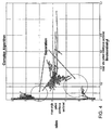
US Provisional Patent Application, Serial No. 60/823,973, filed August 30, 2006 - A plot of the magnitude of admittance against the phase of admittance provides distinct areas of the plot that indicate open or closed airways. Alternatively, the real part of the admittance may be plotted against the imaginary part in an Argand diagram, resulting again in distinct areas of the diagram being associated with open and closed apneas.
- The invention provides an improved apparatus for treating a patient subject to apneas. In particular it relies upon improved methods for determining whether an apnea is closed or open, by identifying sets of values of the complex patient admittance that are respectively characteristic of open or closed apneas. The admittance is the reciprocal of the complex impedance of the apparatus parameterized for example as a two port model of flow impedance or determining resistive and inertial components from a theoretical model employing empirically derived resistive constants and theoretically determined flow inertance constants.
- A sinusoidal (e.g. 4 Hz) pressure oscillation is applied at the input to the airpath, while flow and pressure is measured both at the input and output of the airpath. Based upon the two port model or the more theoretical hose drop model, the admittance is determined from the AC component of the patient airflow (found by subtracting the AC components of vent flow and leak) and the AC component of the mask pressure. The vent flow, in turn, is determined from an improved quadratic relationship to mask pressure in the case of the two port model, or a linearized calculation in the more theoretical hose drop model. The leak is determined from an estimated leak coefficient. The calculation of AC components of these quantities is improved over prior estimations by using Fourier sine and cosine components at the input oscillation frequency rather than by approximating an orthonormal set of functions by square waves.
- In the disclosure is a method for determining patency of the airway of a patient, the method comprising the steps of:
- applying an oscillatory pressure waveform of known frequency to the patient's airway;
- measuring respiratory air flow and pressure at the flow generator;
- calculating the AC values of flow and pressure at the mask from a 2-port impedance model,
- determining that the airway is patent by determining whether the complex admittance is in a region characteristic of patency.
- Advantageously the admittance is determined from the ratio of AC values of patient flow and mask pressure, and there is the step of comparing the value of the complex admittance with ranges of values for which the airway is declared patent.
- The disclosure further includes a method for determining the degree of patency of the airway of a patient, the method comprising the steps of:
- applying an oscillatory pressure waveform of known frequency, magnitude and phase at an entrance to the patient's airway;
- measuring respiratory air flow from the patient;
- determining the magnitude and phase of the component of said air flow at said known frequency induced by said oscillatory pressure waveform; and
- determining the degree of patency as the location of the complex admittance within the region indicative of patency.
- To minimize the effect of the delivery system not supplying a predetermined waveform in the aforementioned method, the pressure waveform actually produced is measured. In this technique we initially apply a waveform of some amplitude at the flow generator, calculate or observe the magnitude of the pressure waveform at the mask, then adjust (typically increasing) the amplitude at the flow generator in order to produce a desired amplitude at the mask. Given that the system is approximately linear for these small signals, the calculation as to how much to increase the driving waveform is a calculation of the radio of the desired to the actual pressure magnitude at the mask. The advantage of this approach is an improvement in the signal to noise ratio.
- The disclosure yet further includes a method for controlling the administration of CPAP treatment to the airway of a patient by means controllable to supply breathable air to the patient's airway continually at a selectable pressure elevated above atmospheric pressure, the method comprising the step of:
- commencing or increasing CPAP treatment pressure if an apnea is occurring, determined by the steps of:
- measuring respiratory air flow from the patient as a function of time; and
- determining the deviation of said admittance from the centroid of the region of patency.
- The invention discloses apparatus for determining patency of the airway of a patient, the apparatus comprising:
- means for applying an oscillatory pressure waveform of known frequency to the patient's airway;
- means for measuring respiratory air flow from the patient; and
- means for determining that the airway is patent if there is an admittance within a patency region at said known frequency induced by said oscillatory pressure waveform.
- The invention yet further discloses apparatus for determining the degree of patency of the airway of a patient, the apparatus comprising:
- means for applying an oscillatory pressure waveform of known frequency and magnitude to the patient's airway;
- means for determining the complex admittance of respiratory air flow from the patient; and
- means for determining the degree of patency as the deviation of said induced admittance from the centroid of a patency region.
- The disclosure further includes a method of distinguishing between open and closed airway apneas of a patient comprising the steps of:
- (i) connecting a respiratory device to a patient via an air delivery tube and a patient interface;
- (ii) delivering an alternating pressure waveform to the patient from the respiratory device to the patient via the air delivery tube;
- (iii) measuring a flow rate and pressure of air at the respiratory device;
- (iv) determining a capacitive component of an air delivery tube impedance;
- (v) determining a patient admittance from said measured flow and pressure of air and said capacitive component;
- (vi) distinguishing between an open and closed airway apnea on the basis of said patient admittance.
- The disclosure further includes a method of distinguishing between open and closed airway apneas of a patient comprising the steps of:
- (i) connecting a respiratory device to a patient via an air delivery tube and a patient interface;
- (ii) delivering an alternating pressure waveform to the patient from the respiratory device to the patient via the air delivery tube;
- (iii) measuring a flow rate and pressure of air at the respiratory device;
- (iv) determining an inductive component of an air delivery tube impedance;
- (v) determining a patient admittance from said measured flow and pressure of air and said capacitive component;
- (vi) distinguishing between an open and closed airway apnea on the basis of said patient admittance.
- In another form patency of the airway is determined to be unknown, or in a "don't know" region. Another aspect is that patency is defined as having a gradual scale from open to closed. Another aspect is that apnea discrimination regions are defined in the complex plane, the regions not necessarily being contiguous. A further refinement is that the discrimination regions may be functions of the average leak level; in particular, the don't-know regions probably increase in size with increasing leak
- The invention is as set out in the claims.
- Embodiments of the invention will now be described with reference to the accompanying drawings, in which:
-
FIG. 1 shows a flow diagram of the basic methodology of an embodiment; -
FIG. 2 shows, in diagrammatic form, apparatus embodying the invention; -
FIG. 3 shows an electronic analogue of the 2-port analysis of the present invention. -
FIG. 4 shows values of the complex admittance based on a detailed algorithm. -
FIG. 5 shows values of the complex admittance based on a simplified algorithm. - The present invention is an improvement upon the embodiments disclosed in
US patent 5,704,345 .FIG. 1 is a flow diagram of the basic methodology of one embodiment of the present invention. Thefirst step 10 of the present invention is the measurement of respiratory flow and pressure at points near the flow generator over time where an apnea is occurring. This information is processed instep 12 to generate admittance values to be used as qualitative measures for subsequent processing. Steps 14-16 detect whether a closed, open or mixed apnea is occurring by comparison of the complex admittance value in a time window with a patency region. - If an apnea is in progress there then follows a determination whether the apnea is open or closed. If an apnea with an open airway is occurring, and, if desired, the event is logged in
step 18. If the result ofstep 16 is that an apnea with a closed airway is occurring, an increase in CPAP treatment pressure occurs instep 20. If desired, step 20 may include the optional logging of the detected abnormality. - In the instance of an apnea with an open airway the CPAP treatment pressure is reduced, in accordance with usual methodologies that seek to set the minimal pressure required to obviate, or at least reduce, the occurrence of apneas. The amount of reduction in
step 22 may, if desired, be zero. - The methodology represented in
FIG. 1 is of a clinical embodiment, where patient CPAP pressure is controlled over time as appropriate. A purely diagnostic embodiment operates in the same manner except it omits the CPAP pressure increase and pressure decrease actions ofstep 20 and step 22 respectively. -
FIG. 2 shows, in diagrammatic form, clinical CPAP apparatus in accordance with one embodiment for implementing the methodology ofFIG. 1 . Amask 30, whether either a nose mask and/or a face mask, is sealingly fitted to a patient's face. Fresh air, or oxygen enriched air, enters themask 30 byflexible tubing 32 which, in turn, is connected with a motor driven turbine (flow generator) 34 to which there is provided anair inlet 36. Themotor 38 for the turbine is controlled by a motor-servo unit 40 to either increase or decrease the pressure of air supplied to themask 30 as CPAP treatment. Themask 30 also includes anexhaust port 42 that is close to the junction of thetubing 34 with themask 30. - Adjacent to the
flow generator 34 is a flow-resistive element 44. This can take the form of an iris across which a differential pressure exists. The mask side of the flow-resistive element 44 is connected by asmall bore tube 46 to apressure transducer 48 and to an input of adifferential pressure transducer 50. Pressure at the other side of the flow-resistive element 44 is conveyed to the other input of thedifferential pressure transducer 50 by anothersmall bore tube 52. - The
pressure transducer 48 generates an electrical signal in proportion to the flow pressure, which is amplified byamplifier 56 and passed both to a multiplexer/ADC unit 58 and to the motor-servo unit 40. The function of the signal provided to the motor-servo unit 40 is as a form of feedback to ensure that the static pressure is controlled to be closely approximate to the set point pressure. - The differential pressure sensed across the flow-
resistive element 44 is output as an electrical signal from thedifferential pressure transducer 50, and amplified by anotheramplifier 60. The output signal from theamplifier 56 therefore represents a measure of the mask or respiratory airflow rate. Thecontroller 62 is programmed to perform a number of processing functions. - The pressure and flow may be considered to be composed of steady state values and AC values, the latter reflecting the effect of a imposed oscillatory signal on the pressure having a frequency of 4 Hz. In what follows, a "steady-state" quantity is either (a) one from which the oscillatory component has been deliberately removed, for example by a filtering operation, or (b) is the result of a calculation based partly or wholly on quantities from which the oscillatory component has been removed, or (c) is a quantity which is calculated based on instantaneous quantities, such as pressure and flow measured at the flow generator (which thus include an oscillatory component), and a model of the airpath and patient leak which either partly or wholly ignores the reactive components of the system and treats it simply as a (possibly nonlinear) system of resistances. The steady state pressure loss along
tubing 32 is calculated from the flow through the tube, and knowledge of the static pressure-flow characteristic of the tubing, for example by table lookup. The steady state pressure at the mask is then calculated by subtracting the tube pressure loss. The pressure loss alongtube 32 is then added to the desired set pressure at the mask to yield the desired instantaneous pressure at thepressure generator 34. The flow through theexhaust 42 is calculated from the pressure at the mask from the pressure-flow characteristic of the exhaust, for example by table lookup. The steady state mask flow is calculated by subtracting the flow through theexhaust 42 from the flow through thetubing 32. The steady state patient flow is then calculated by subtracting the steady-state estimated leak, which may be determined for example in a CPAP device by a 1st order low pass filter with a time constant of 10 seconds whose input is the instantaneous mask flow, from the steady-state mask flow. - The methodology put into place by the
controller 62 will now be described with reference to the apparatus ofFIG. 2 . If the patient respiratory flow is very low or zero (note that the mask flow will not cease when the patient is apnoeic if there is any leak), a determination of airway patency (steps 14-16) is made by using an externally induced oscillation technique. If the airway is open, but the respiratory muscles are relaxed (i.e. a central apnea with open airway), then small externally originating fluctuations in the mask pressure will induce a small respiratory airflow by inflating and deflating the lungs, and by compressing and decompressing the gas in the lungs. Conversely, if the airway is closed, no airflow will be induced. This is quantified as follows: - The admittance Y is given by

- In order to decide whether the airway is open, the complex value of the patient admittance, Y, is compared with a region of values. The value of this threshold may be selected on the basis of the following observations.
- An explanation for the angle being a better classifier than the magnitude is possibly related to the interaction of the complex impedances in the circuit. The leak and vent flow are essentially non-linear resistances with no complex (j) component. The patient is basically a resistance and compliance (capacitance) in series to ground. The hose drop also has a complex component in the form of the inertance of the flow. So the magnitude of the overall impedance is influenced by all components (hose, leak, vent flow, patient airway) as they all have real parts. However the imaginary component is the interaction between the inertial hose drop and the capacitive lungs. It is comparing the relative "strengths" of the inertial and capacitive reactances.
- It is also possible to use the real and imaginary parts of the impedance rather than the angle and magnitude. This has an advantage of reduced CPU load. The magnitude calculation requires a square root and the angle calculation involves an inverse tan. (Both of these can be done to easily the required accuracy by techniques involving lookup tables, which are computationally fairly cheap.) Using both the real and imaginary or magnitude and angle gives a more robust classification. The grouping of the open and closed values becomes much more apparent.
- As determined from the values in
Fig. 4 , a possible set of thresholds would be
 angle = ARG(patient_admittance)
 if ( angle < -2 OR angle > 1.2 )
       AirwayState = CLOSED;
 else if ( angle < 0.9 AND angle > -1.5 )
       AirwayState = OPEN;
 else
       AirwayState = UNKNOWN;
 end if
where angle is in radians. The acceptable values for the thresholds may be any that permits the separation of values representing open and closed apneas determined from 

where the overbars indicate the mean over the measurement period. During apnea the leak is equal to the total non-vent flow


- K 1,K 2 = empirically derived constants
- KL = theoretically determined flow inertance constant
- QFG = FG Flow
- ρ = air density (1.19 kg/m3)
- l = tube length (2 or 3m)

- K 1, K 2 = empirically derived constants
-
Q FC = Mean FG Flow


Claims (8)
- An apparatus for distinguishing between open and closed airway apneas of a patient who is connected to a respiratory device via an air delivery tube (32) and a patient interface (30), said apparatus comprising:(i) means (34, 38, 40) for delivering an alternating pressure waveform to the patient from the respiratory device to the patient via the air delivery tube (32);(ii) means (48, 50, 56) for measuring a flow rate and pressure of air at the respiratory device; andcharacterized by(iii) means (62) for determining a capacitive component or an inductive component of an air delivery tube (32) impedance;(iv) means (62) for determining a patient admittance from said measured flow and pressure of air and said capacitive component or said inductive component, respectively;(v) means (62) for determining the phase angle of the admittance or means (62) for determining the imaginary component of the admittance;(vi) means (62) for distinguishing between an open and closed airway apnea on the basis of the phase angle or both the real and imaginary components of said patient admittance.
- The apparatus of claim 1 further comprising means (62) for correcting the said flow rate for leak.
- The apparatus of claim 1 or 2 further comprising means (62) for correcting the said flow rate for vent flow.
- The apparatus of any one of claims 1-3, the apparatus delivers the alternating pressure waveform if patient respiratory airflow is low or zero.
- The apparatus of any one of claims 1-4 further comprising means (62) for determining the magnitude of the admittance.
- The apparatus of any one of claims 1-5 whereby said alternating pressure waveform has a frequency of approximately 4 Hz.
- The apparatus of any one of claims 1-6 whereby approximately the first 250ms of flow or pressure data following an application of the pressure waveform are not measured.
- The apparatus of any one of claims 1-7, further comprising means for comparing the patient admittance with admittance determined during normal breathing.
Priority Applications (1)
| Application Number | Priority Date | Filing Date | Title |
|---|---|---|---|
| EP16158562.5A EP3056236B1 (en) | 2006-08-30 | 2007-08-30 | Distinguishing closed and open respiratory airway apneas by complex admittance values |
Applications Claiming Priority (3)
| Application Number | Priority Date | Filing Date | Title |
|---|---|---|---|
| US82397306P | 2006-08-30 | 2006-08-30 | |
| US91614707P | 2007-05-04 | 2007-05-04 | |
| PCT/AU2007/001257 WO2008025080A1 (en) | 2006-08-30 | 2007-08-30 | Distinguishing closed and open respiratory airway apneas by complex admittance values |
Related Child Applications (1)
| Application Number | Title | Priority Date | Filing Date |
|---|---|---|---|
| EP16158562.5A Division EP3056236B1 (en) | 2006-08-30 | 2007-08-30 | Distinguishing closed and open respiratory airway apneas by complex admittance values |
Publications (3)
| Publication Number | Publication Date |
|---|---|
| EP2056911A1 EP2056911A1 (en) | 2009-05-13 |
| EP2056911A4 EP2056911A4 (en) | 2011-11-30 |
| EP2056911B1 true EP2056911B1 (en) | 2016-03-09 |
Family
ID=39135415
Family Applications (2)
| Application Number | Title | Priority Date | Filing Date |
|---|---|---|---|
| EP07800218.5A Active EP2056911B1 (en) | 2006-08-30 | 2007-08-30 | Apparatus for distinguishing between closed and open respiratory airway apneas by complex admittance values |
| EP16158562.5A Active EP3056236B1 (en) | 2006-08-30 | 2007-08-30 | Distinguishing closed and open respiratory airway apneas by complex admittance values |
Family Applications After (1)
| Application Number | Title | Priority Date | Filing Date |
|---|---|---|---|
| EP16158562.5A Active EP3056236B1 (en) | 2006-08-30 | 2007-08-30 | Distinguishing closed and open respiratory airway apneas by complex admittance values |
Country Status (7)
| Country | Link |
|---|---|
| US (4) | US9028423B2 (en) |
| EP (2) | EP2056911B1 (en) |
| JP (3) | JP2010501291A (en) |
| CN (3) | CN102894979B (en) |
| AU (1) | AU2007291951B2 (en) |
| NZ (3) | NZ607004A (en) |
| WO (1) | WO2008025080A1 (en) |
Families Citing this family (21)
| Publication number | Priority date | Publication date | Assignee | Title |
|---|---|---|---|---|
| ES2411513T3 (en) * | 2007-11-08 | 2013-07-05 | Inolact Ltd. | Measurement of excreted fluids from an organ |
| JP5198162B2 (en) * | 2008-03-10 | 2013-05-15 | チェスト株式会社 | Respiratory impedance measuring device and measuring method thereof |
| JP5210676B2 (en) * | 2008-03-19 | 2013-06-12 | パナソニックヘルスケア株式会社 | Temperature control device, air conditioner and electric blanket |
| US9878113B2 (en) | 2008-06-13 | 2018-01-30 | Resmed Limited | Pressure control in respiratory treatment apparatus |
| AU2010213352B2 (en) | 2009-02-11 | 2013-04-04 | ResMed Pty Ltd | Acoustic detection for respiratory treatment apparatus |
| WO2010119843A1 (en) * | 2009-04-13 | 2010-10-21 | チェスト株式会社 | Respiration impedance measuring device and respiration impedance display method |
| AU2010206053B2 (en) | 2009-07-31 | 2014-08-07 | ResMed Pty Ltd | Wire Heated Tube with Temperature Control System, Tube Type Detection, and Active Over Temperature Protection for Humidifier for Respiratory Apparatus |
| DE102009046541A1 (en) * | 2009-11-09 | 2011-05-12 | Medin Medical Innovations Gmbh | Compressed air control device for a CPAP device and corresponding CPAP system |
| WO2012014106A1 (en) * | 2010-07-27 | 2012-02-02 | Koninklijke Philips Electronics N.V. | Leak estimation using function estimation. |
| JP6543192B2 (en) | 2012-09-28 | 2019-07-10 | フィッシャー アンド ペイケル ヘルスケア リミテッド | Humidifying respiratory control |
| NZ743034A (en) | 2013-02-01 | 2019-12-20 | ResMed Pty Ltd | Wire heated tube with temperature control system for humidifier for respiratory apparatus |
| US20170181663A1 (en) * | 2014-05-26 | 2017-06-29 | Spiro Medical As | System for monitoring respiratory effort |
| CN114569848A (en) * | 2015-08-14 | 2022-06-03 | 瑞思迈私人有限公司 | Monitoring respiratory pressure therapy |
| US20170361041A1 (en) * | 2016-06-16 | 2017-12-21 | Loewenstein Medical Technology S.A. | Respirator for apap respiration using oscillatory pressure |
| EP3541458B1 (en) * | 2016-11-18 | 2021-11-03 | ResMed Pty Ltd | Apparatus for ventilatory treatment of respiratory disorders |
| CN108685575B (en) * | 2017-04-10 | 2023-06-02 | 中国人民解放军总医院 | Respiratory system function test method and device |
| CN109939311A (en) * | 2017-12-20 | 2019-06-28 | 北京谊安医疗系统股份有限公司 | The judgment method and ventilator of breathing circuit obstruction block warning device |
| CN109497949B (en) * | 2018-12-12 | 2022-04-22 | 深圳融昕医疗科技有限公司 | Method and device for detecting apnea type, breathing machine and storage medium |
| CN109730681B (en) * | 2018-12-29 | 2021-07-02 | 北京谊安医疗系统股份有限公司 | Method and device for judging obstruction of patient airway and medical breathing equipment |
| CN113133759B (en) * | 2021-04-08 | 2023-06-16 | 贵州宇悦生命科技股份有限公司 | Breathing auxiliary health monitoring system based on big data and use control method |
| CN116831558B (en) * | 2023-06-30 | 2024-03-29 | 浙江柯洛德健康科技有限公司 | Breath impedance calculation method and calculation device based on forced oscillation |
Family Cites Families (41)
| Publication number | Priority date | Publication date | Assignee | Title |
|---|---|---|---|---|
| DE2413960C3 (en) * | 1974-03-22 | 1979-06-13 | Siemens Ag, 1000 Berlin Und 8000 Muenchen | Device for determining the airway resistance |
| FR2264515B1 (en) | 1974-03-22 | 1977-03-25 | Siemens Ag | |
| DE2714216C2 (en) * | 1977-03-30 | 1978-12-07 | Siemens Ag, 1000 Berlin Und 8000 Muenchen | Device for determining the airway impedance |
| DE3176339D1 (en) * | 1980-11-26 | 1987-09-10 | Tritec Ind Inc | Respirator apparatus and method |
| US5199424A (en) | 1987-06-26 | 1993-04-06 | Sullivan Colin E | Device for monitoring breathing during sleep and control of CPAP treatment that is patient controlled |
| DE3903857A1 (en) | 1988-12-13 | 1990-06-21 | Schumann Klaus | IMPROVED DETERMINATION OF RESPIRATORY RESISTANCE AFTER THE OSCILLATION METHOD |
| CN1024114C (en) * | 1989-02-24 | 1994-04-06 | 航天工业部第二研究院第四总体设计部 | Microcomputerized controller of respirator |
| CN1046397A (en) * | 1989-04-15 | 1990-10-24 | 铁道部柳州机车车辆厂 | Computer controlled respirator system |
| US5134995A (en) * | 1989-05-19 | 1992-08-04 | Puritan-Bennett Corporation | Inspiratory airway pressure system with admittance determining apparatus and method |
| US5845636A (en) | 1989-05-19 | 1998-12-08 | Puritan Bennett Corporation | Method and apparatus for maintaining patient airway patency |
| US5259373A (en) * | 1989-05-19 | 1993-11-09 | Puritan-Bennett Corporation | Inspiratory airway pressure system controlled by the detection and analysis of patient airway sounds |
| US5148802B1 (en) | 1989-09-22 | 1997-08-12 | Respironics Inc | Method and apparatus for maintaining airway patency to treat sleep apnea and other disorders |
| US6675797B1 (en) * | 1993-11-05 | 2004-01-13 | Resmed Limited | Determination of patency of the airway |
| EP0920845B1 (en) | 1993-11-05 | 2004-04-21 | ResMed Limited | Detection of apnea |
| NO319498B1 (en) * | 1996-07-30 | 2005-08-22 | Weinmann G Geraete Med | Respiratory apparatus for the therapy of sleep apnea ± and methods of controlling it. |
| ATE383814T1 (en) | 1997-03-17 | 2008-02-15 | Vivometrics Inc | METHOD FOR RESPIRATORY WAVE FORM ANALYSIS IN RELATION TO ITS INFLUENCE ON NEUROMUSCULAR BREATHING |
| FR2767466B1 (en) * | 1997-08-25 | 1999-10-15 | Taema | METHOD FOR DETERMINING THE IMAGE OF A NASAL AND / OR ORAL RESPIRATORY FLOW OF A USER |
| US6142952A (en) * | 1997-10-29 | 2000-11-07 | The Board Of Regents, The University Of Texas System | Method and apparatus for detection and diagnosis of airway obstruction degree |
| AUPP026997A0 (en) * | 1997-11-07 | 1997-12-04 | Resmed Limited | Administration of cpap treatment pressure in presence of apnea |
| US6257234B1 (en) * | 1998-08-21 | 2001-07-10 | Respironics, Inc. | Apparatus and method for determining respiratory mechanics of a patient and for controlling a ventilator based thereon |
| US6287264B1 (en) * | 1999-04-23 | 2001-09-11 | The Trustees Of Tufts College | System for measuring respiratory function |
| US7708697B2 (en) * | 2000-04-20 | 2010-05-04 | Pulmosonix Pty Ltd | Method and apparatus for determining conditions of biological tissues |
| JP3377776B2 (en) | 2000-06-27 | 2003-02-17 | 関西電力株式会社 | Islanding detection method and islanding detection device for distributed power supply |
| US6349724B1 (en) | 2000-07-05 | 2002-02-26 | Compumedics Sleep Pty. Ltd. | Dual-pressure blower for positive air pressure device |
| EP1349600B1 (en) * | 2000-12-11 | 2017-03-08 | ResMed Limited | Apparatus for stroke patient assessment and treatment |
| JP4212778B2 (en) * | 2001-01-10 | 2009-01-21 | 帝人株式会社 | Positive pressure ventilator |
| JP5059260B2 (en) * | 2001-03-29 | 2012-10-24 | 帝人株式会社 | Medical device remote monitoring method |
| ITMI20021273A1 (en) * | 2002-06-11 | 2003-12-11 | Milano Politecnico | SYSTEM AND METHOD FOR THE AUTOMATIC DETECTION OF THE EXPIRATORY FLOW LIMITATION |
| AU2002951984A0 (en) | 2002-10-10 | 2002-10-31 | Compumedics Limited | Sleep quality and auto cpap awakening |
| DE10253947C1 (en) | 2002-11-19 | 2003-12-04 | Seleon Gmbh | Pressure loss compensation method for respiration device with calculation of pressure loss from measured air flow |
| DE10253935B3 (en) | 2002-11-19 | 2004-03-25 | Seleon Gmbh | Controlling pressure delivered by continuous positive airway pressure device involves slow, quasi-ramp-shaped reduction of pressure delivered by device as long as there is no respiratory event |
| US7114497B2 (en) * | 2003-07-18 | 2006-10-03 | Acoba, Llc | Method and system of individually controlling airway pressure of a patient's nares |
| WO2005068005A1 (en) * | 2004-01-05 | 2005-07-28 | Trustees Of Boston University | Servo-controlled pneumatic pressure oscillator for respiratory impedance measurements and high-frequency ventilation |
| JP4333378B2 (en) * | 2004-01-28 | 2009-09-16 | 株式会社Ihi | Method and apparatus for reducing noise emission of suction silencer for supercharger |
| AU2005237191A1 (en) * | 2004-05-04 | 2005-11-10 | Dalhousie University | Method of assessment of airway variability in airway hyperresponsiveness |
| US20050284469A1 (en) | 2004-06-25 | 2005-12-29 | Tobia Ronald L | Integrated control of ventilator and nebulizer operation |
| CN100360077C (en) * | 2004-07-30 | 2008-01-09 | 上海第二医科大学附属仁济医院 | Dimesize non-traumatic monitoring system of pressure and temperature for internal envirnoment or bronchia |
| EP1809357B1 (en) * | 2004-10-05 | 2012-12-05 | Universiteit Antwerpen | Diagnostics and treatment of sleep apnea |
| CN100518637C (en) * | 2005-01-05 | 2009-07-29 | 深圳迈瑞生物医疗电子股份有限公司 | Method and apparatus for monitoring human breathing mechanics parameters based on differential pressure flow sensor |
| ES2585642T3 (en) * | 2005-06-21 | 2016-10-07 | Breas Medical Ab | Device, method and software to compensate for fan leaks |
| JP4642626B2 (en) | 2005-10-11 | 2011-03-02 | 博 中野 | Apnea / hypopnea automatic detection device, detection method, program, and recording medium |
-
2007
- 2007-08-30 NZ NZ60700407A patent/NZ607004A/en unknown
- 2007-08-30 EP EP07800218.5A patent/EP2056911B1/en active Active
- 2007-08-30 CN CN201210393964.8A patent/CN102894979B/en active Active
- 2007-08-30 CN CNA2007800320898A patent/CN101511417A/en active Pending
- 2007-08-30 NZ NZ596379A patent/NZ596379A/en unknown
- 2007-08-30 JP JP2009525858A patent/JP2010501291A/en active Pending
- 2007-08-30 US US12/376,136 patent/US9028423B2/en active Active
- 2007-08-30 WO PCT/AU2007/001257 patent/WO2008025080A1/en active Application Filing
- 2007-08-30 EP EP16158562.5A patent/EP3056236B1/en active Active
- 2007-08-30 AU AU2007291951A patent/AU2007291951B2/en active Active
- 2007-08-30 CN CN201610340861.3A patent/CN105920710B/en active Active
- 2007-08-30 NZ NZ574482A patent/NZ574482A/en unknown
-
2011
- 2011-11-07 JP JP2011243787A patent/JP5959042B2/en active Active
-
2014
- 2014-11-28 JP JP2014241301A patent/JP6045081B2/en active Active
-
2015
- 2015-03-10 US US14/643,233 patent/US9597012B2/en active Active
-
2017
- 2017-01-31 US US15/420,282 patent/US9782121B2/en active Active
- 2017-09-05 US US15/695,241 patent/US10918329B2/en active Active
Non-Patent Citations (1)
| Title |
|---|
| R. FARRÉ ET AL: "Assessment of bronchial reactivity by forced oscillation admittance avoids the upper airway artefact", EUROPEAN RESPIRATORY JOURNAL, vol. 13, no. 4, 1 April 1999 (1999-04-01), pages 761 - 766, XP055112713, ISSN: 0903-1936, DOI: 10.1034/j.1399-3003.1999.13d11.x * |
Also Published As
| Publication number | Publication date |
|---|---|
| AU2007291951B2 (en) | 2013-06-06 |
| JP5959042B2 (en) | 2016-08-02 |
| AU2007291951A1 (en) | 2008-03-06 |
| US10918329B2 (en) | 2021-02-16 |
| EP2056911A4 (en) | 2011-11-30 |
| CN105920710B (en) | 2018-09-18 |
| JP2012086025A (en) | 2012-05-10 |
| JP2015119961A (en) | 2015-07-02 |
| US9782121B2 (en) | 2017-10-10 |
| WO2008025080A1 (en) | 2008-03-06 |
| EP3056236A1 (en) | 2016-08-17 |
| US20180085052A1 (en) | 2018-03-29 |
| EP3056236B1 (en) | 2019-09-25 |
| US9028423B2 (en) | 2015-05-12 |
| JP2010501291A (en) | 2010-01-21 |
| NZ607004A (en) | 2014-08-29 |
| CN102894979B (en) | 2016-07-06 |
| NZ574482A (en) | 2012-08-31 |
| JP6045081B2 (en) | 2016-12-14 |
| US20150173649A1 (en) | 2015-06-25 |
| CN105920710A (en) | 2016-09-07 |
| EP2056911A1 (en) | 2009-05-13 |
| US9597012B2 (en) | 2017-03-21 |
| US20170135630A1 (en) | 2017-05-18 |
| CN101511417A (en) | 2009-08-19 |
| NZ596379A (en) | 2013-02-22 |
| CN102894979A (en) | 2013-01-30 |
| US20090326403A1 (en) | 2009-12-31 |
Similar Documents
| Publication | Publication Date | Title |
|---|---|---|
| US10918329B2 (en) | Distinguishing closed and open respiratory airway apneas by complex admittance values | |
| US11351319B2 (en) | Determination of apnea/hypopnea during CPAP treatment | |
| US5740795A (en) | Estimation of flow and detection of breathing in CPAP treatment | |
| US6279569B1 (en) | Determination of leak and respiratory airflow | |
| US6237593B1 (en) | Estimation of flow and detection of breathing CPAP treatment | |
| JP2018507748A5 (en) | ||
| NZ552070A (en) | Method and device for carrying out a signal-processing viewing of a measurement signal that is correlated to the respiratory activity on an individual | |
| AU2015249041B2 (en) | Distinguishing Closed and Open Respiratory Airway Apneas by Complex Admittance Values | |
| AU2013213685B2 (en) | Distinguishing Closed and Open Respiratory Airway Apneas by Complex Admittance Values | |
| AU2005200987B2 (en) | Determination of Leak and Respiratory Airflow |
Legal Events
| Date | Code | Title | Description |
|---|---|---|---|
| PUAI | Public reference made under article 153(3) epc to a published international application that has entered the european phase |
Free format text: ORIGINAL CODE: 0009012 |
|
| 17P | Request for examination filed |
Effective date: 20090319 |
|
| AK | Designated contracting states |
Kind code of ref document: A1 Designated state(s): AT BE BG CH CY CZ DE DK EE ES FI FR GB GR HU IE IS IT LI LT LU LV MC MT NL PL PT RO SE SI SK TR |
|
| AX | Request for extension of the european patent |
Extension state: AL BA HR MK RS |
|
| A4 | Supplementary search report drawn up and despatched |
Effective date: 20111103 |
|
| RIC1 | Information provided on ipc code assigned before grant |
Ipc: A61B 5/085 20060101ALI20111027BHEP Ipc: A61M 16/06 20060101ALI20111027BHEP Ipc: A61M 16/00 20060101AFI20111027BHEP |
|
| DAX | Request for extension of the european patent (deleted) | ||
| 17Q | First examination report despatched |
Effective date: 20130614 |
|
| GRAP | Despatch of communication of intention to grant a patent |
Free format text: ORIGINAL CODE: EPIDOSNIGR1 |
|
| INTG | Intention to grant announced |
Effective date: 20150825 |
|
| GRAS | Grant fee paid |
Free format text: ORIGINAL CODE: EPIDOSNIGR3 |
|
| GRAA | (expected) grant |
Free format text: ORIGINAL CODE: 0009210 |
|
| AK | Designated contracting states |
Kind code of ref document: B1 Designated state(s): AT BE BG CH CY CZ DE DK EE ES FI FR GB GR HU IE IS IT LI LT LU LV MC MT NL PL PT RO SE SI SK TR |
|
| REG | Reference to a national code |
Ref country code: GB Ref legal event code: FG4D |
|
| REG | Reference to a national code |
Ref country code: AT Ref legal event code: REF Ref document number: 779036 Country of ref document: AT Kind code of ref document: T Effective date: 20160315 Ref country code: CH Ref legal event code: EP |
|
| REG | Reference to a national code |
Ref country code: IE Ref legal event code: FG4D |
|
| REG | Reference to a national code |
Ref country code: CH Ref legal event code: NV Representative=s name: VOSSIUS AND PARTNER, CH |
|
| REG | Reference to a national code |
Ref country code: DE Ref legal event code: R096 Ref document number: 602007045179 Country of ref document: DE |
|
| REG | Reference to a national code |
Ref country code: SE Ref legal event code: TRGR |
|
| REG | Reference to a national code |
Ref country code: LT Ref legal event code: MG4D |
|
| REG | Reference to a national code |
Ref country code: FR Ref legal event code: PLFP Year of fee payment: 10 |
|
| REG | Reference to a national code |
Ref country code: NL Ref legal event code: MP Effective date: 20160309 |
|
| REG | Reference to a national code |
Ref country code: CH Ref legal event code: PFA Owner name: RESMED LIMITED, AU Free format text: FORMER OWNER: RESMED LIMITED, AU |
|
| PG25 | Lapsed in a contracting state [announced via postgrant information from national office to epo] |
Ref country code: ES Free format text: LAPSE BECAUSE OF FAILURE TO SUBMIT A TRANSLATION OF THE DESCRIPTION OR TO PAY THE FEE WITHIN THE PRESCRIBED TIME-LIMIT Effective date: 20160309 Ref country code: GR Free format text: LAPSE BECAUSE OF FAILURE TO SUBMIT A TRANSLATION OF THE DESCRIPTION OR TO PAY THE FEE WITHIN THE PRESCRIBED TIME-LIMIT Effective date: 20160610 Ref country code: FI Free format text: LAPSE BECAUSE OF FAILURE TO SUBMIT A TRANSLATION OF THE DESCRIPTION OR TO PAY THE FEE WITHIN THE PRESCRIBED TIME-LIMIT Effective date: 20160309 |
|
| REG | Reference to a national code |
Ref country code: AT Ref legal event code: MK05 Ref document number: 779036 Country of ref document: AT Kind code of ref document: T Effective date: 20160309 |
|
| PG25 | Lapsed in a contracting state [announced via postgrant information from national office to epo] |
Ref country code: PL Free format text: LAPSE BECAUSE OF FAILURE TO SUBMIT A TRANSLATION OF THE DESCRIPTION OR TO PAY THE FEE WITHIN THE PRESCRIBED TIME-LIMIT Effective date: 20160309 Ref country code: LV Free format text: LAPSE BECAUSE OF FAILURE TO SUBMIT A TRANSLATION OF THE DESCRIPTION OR TO PAY THE FEE WITHIN THE PRESCRIBED TIME-LIMIT Effective date: 20160309 Ref country code: LT Free format text: LAPSE BECAUSE OF FAILURE TO SUBMIT A TRANSLATION OF THE DESCRIPTION OR TO PAY THE FEE WITHIN THE PRESCRIBED TIME-LIMIT Effective date: 20160309 Ref country code: NL Free format text: LAPSE BECAUSE OF FAILURE TO SUBMIT A TRANSLATION OF THE DESCRIPTION OR TO PAY THE FEE WITHIN THE PRESCRIBED TIME-LIMIT Effective date: 20160309 |
|
| PG25 | Lapsed in a contracting state [announced via postgrant information from national office to epo] |
Ref country code: IS Free format text: LAPSE BECAUSE OF FAILURE TO SUBMIT A TRANSLATION OF THE DESCRIPTION OR TO PAY THE FEE WITHIN THE PRESCRIBED TIME-LIMIT Effective date: 20160709 Ref country code: EE Free format text: LAPSE BECAUSE OF FAILURE TO SUBMIT A TRANSLATION OF THE DESCRIPTION OR TO PAY THE FEE WITHIN THE PRESCRIBED TIME-LIMIT Effective date: 20160309 |
|
| PGFP | Annual fee paid to national office [announced via postgrant information from national office to epo] |
Ref country code: CH Payment date: 20160812 Year of fee payment: 10 |
|
| PG25 | Lapsed in a contracting state [announced via postgrant information from national office to epo] |
Ref country code: RO Free format text: LAPSE BECAUSE OF FAILURE TO SUBMIT A TRANSLATION OF THE DESCRIPTION OR TO PAY THE FEE WITHIN THE PRESCRIBED TIME-LIMIT Effective date: 20160309 Ref country code: PT Free format text: LAPSE BECAUSE OF FAILURE TO SUBMIT A TRANSLATION OF THE DESCRIPTION OR TO PAY THE FEE WITHIN THE PRESCRIBED TIME-LIMIT Effective date: 20160711 Ref country code: AT Free format text: LAPSE BECAUSE OF FAILURE TO SUBMIT A TRANSLATION OF THE DESCRIPTION OR TO PAY THE FEE WITHIN THE PRESCRIBED TIME-LIMIT Effective date: 20160309 Ref country code: SK Free format text: LAPSE BECAUSE OF FAILURE TO SUBMIT A TRANSLATION OF THE DESCRIPTION OR TO PAY THE FEE WITHIN THE PRESCRIBED TIME-LIMIT Effective date: 20160309 Ref country code: CZ Free format text: LAPSE BECAUSE OF FAILURE TO SUBMIT A TRANSLATION OF THE DESCRIPTION OR TO PAY THE FEE WITHIN THE PRESCRIBED TIME-LIMIT Effective date: 20160309 |
|
| PGFP | Annual fee paid to national office [announced via postgrant information from national office to epo] |
Ref country code: SE Payment date: 20160811 Year of fee payment: 10 |
|
| REG | Reference to a national code |
Ref country code: DE Ref legal event code: R097 Ref document number: 602007045179 Country of ref document: DE |
|
| PG25 | Lapsed in a contracting state [announced via postgrant information from national office to epo] |
Ref country code: BE Free format text: LAPSE BECAUSE OF FAILURE TO SUBMIT A TRANSLATION OF THE DESCRIPTION OR TO PAY THE FEE WITHIN THE PRESCRIBED TIME-LIMIT Effective date: 20160309 Ref country code: IT Free format text: LAPSE BECAUSE OF FAILURE TO SUBMIT A TRANSLATION OF THE DESCRIPTION OR TO PAY THE FEE WITHIN THE PRESCRIBED TIME-LIMIT Effective date: 20160309 |
|
| PLBE | No opposition filed within time limit |
Free format text: ORIGINAL CODE: 0009261 |
|
| STAA | Information on the status of an ep patent application or granted ep patent |
Free format text: STATUS: NO OPPOSITION FILED WITHIN TIME LIMIT |
|
| PG25 | Lapsed in a contracting state [announced via postgrant information from national office to epo] |
Ref country code: DK Free format text: LAPSE BECAUSE OF FAILURE TO SUBMIT A TRANSLATION OF THE DESCRIPTION OR TO PAY THE FEE WITHIN THE PRESCRIBED TIME-LIMIT Effective date: 20160309 |
|
| 26N | No opposition filed |
Effective date: 20161212 |
|
| PG25 | Lapsed in a contracting state [announced via postgrant information from national office to epo] |
Ref country code: BG Free format text: LAPSE BECAUSE OF FAILURE TO SUBMIT A TRANSLATION OF THE DESCRIPTION OR TO PAY THE FEE WITHIN THE PRESCRIBED TIME-LIMIT Effective date: 20160609 |
|
| PG25 | Lapsed in a contracting state [announced via postgrant information from national office to epo] |
Ref country code: MC Free format text: LAPSE BECAUSE OF FAILURE TO SUBMIT A TRANSLATION OF THE DESCRIPTION OR TO PAY THE FEE WITHIN THE PRESCRIBED TIME-LIMIT Effective date: 20160309 |
|
| PG25 | Lapsed in a contracting state [announced via postgrant information from national office to epo] |
Ref country code: SI Free format text: LAPSE BECAUSE OF FAILURE TO SUBMIT A TRANSLATION OF THE DESCRIPTION OR TO PAY THE FEE WITHIN THE PRESCRIBED TIME-LIMIT Effective date: 20160309 |
|
| REG | Reference to a national code |
Ref country code: IE Ref legal event code: MM4A |
|
| REG | Reference to a national code |
Ref country code: FR Ref legal event code: PLFP Year of fee payment: 11 |
|
| PG25 | Lapsed in a contracting state [announced via postgrant information from national office to epo] |
Ref country code: IE Free format text: LAPSE BECAUSE OF NON-PAYMENT OF DUE FEES Effective date: 20160830 |
|
| PG25 | Lapsed in a contracting state [announced via postgrant information from national office to epo] |
Ref country code: LU Free format text: LAPSE BECAUSE OF NON-PAYMENT OF DUE FEES Effective date: 20160830 |
|
| REG | Reference to a national code |
Ref country code: CH Ref legal event code: PL |
|
| PG25 | Lapsed in a contracting state [announced via postgrant information from national office to epo] |
Ref country code: CH Free format text: LAPSE BECAUSE OF NON-PAYMENT OF DUE FEES Effective date: 20170831 Ref country code: LI Free format text: LAPSE BECAUSE OF NON-PAYMENT OF DUE FEES Effective date: 20170831 Ref country code: SE Free format text: LAPSE BECAUSE OF NON-PAYMENT OF DUE FEES Effective date: 20170831 |
|
| PG25 | Lapsed in a contracting state [announced via postgrant information from national office to epo] |
Ref country code: HU Free format text: LAPSE BECAUSE OF FAILURE TO SUBMIT A TRANSLATION OF THE DESCRIPTION OR TO PAY THE FEE WITHIN THE PRESCRIBED TIME-LIMIT; INVALID AB INITIO Effective date: 20070830 Ref country code: CY Free format text: LAPSE BECAUSE OF FAILURE TO SUBMIT A TRANSLATION OF THE DESCRIPTION OR TO PAY THE FEE WITHIN THE PRESCRIBED TIME-LIMIT Effective date: 20160309 |
|
| PG25 | Lapsed in a contracting state [announced via postgrant information from national office to epo] |
Ref country code: TR Free format text: LAPSE BECAUSE OF FAILURE TO SUBMIT A TRANSLATION OF THE DESCRIPTION OR TO PAY THE FEE WITHIN THE PRESCRIBED TIME-LIMIT Effective date: 20160309 Ref country code: MT Free format text: LAPSE BECAUSE OF NON-PAYMENT OF DUE FEES Effective date: 20160831 |
|
| REG | Reference to a national code |
Ref country code: FR Ref legal event code: PLFP Year of fee payment: 12 |
|
| REG | Reference to a national code |
Ref country code: DE Ref legal event code: R082 Ref document number: 602007045179 Country of ref document: DE Representative=s name: VOSSIUS & PARTNER PATENTANWAELTE RECHTSANWAELT, DE Ref country code: DE Ref legal event code: R081 Ref document number: 602007045179 Country of ref document: DE Owner name: RES MED PTY LTD, BELLA VISTA, AU Free format text: FORMER OWNER: RESMED LIMITED, BELLA VISTA, NEW SOUTH WALES, AU |
|
| PGFP | Annual fee paid to national office [announced via postgrant information from national office to epo] |
Ref country code: GB Payment date: 20230720 Year of fee payment: 17 |
|
| PGFP | Annual fee paid to national office [announced via postgrant information from national office to epo] |
Ref country code: FR Payment date: 20230720 Year of fee payment: 17 Ref country code: DE Payment date: 20230720 Year of fee payment: 17 |