EP2056121A1 - Mobile unit positioning device - Google Patents
Mobile unit positioning device Download PDFInfo
- Publication number
- EP2056121A1 EP2056121A1 EP07832501A EP07832501A EP2056121A1 EP 2056121 A1 EP2056121 A1 EP 2056121A1 EP 07832501 A EP07832501 A EP 07832501A EP 07832501 A EP07832501 A EP 07832501A EP 2056121 A1 EP2056121 A1 EP 2056121A1
- Authority
- EP
- European Patent Office
- Prior art keywords
- ionospheric
- delay error
- ionospheric delay
- state information
- moving body
- Prior art date
- Legal status (The legal status is an assumption and is not a legal conclusion. Google has not performed a legal analysis and makes no representation as to the accuracy of the status listed.)
- Granted
Links
- 238000012937 correction Methods 0.000 claims description 12
- 239000005433 ionosphere Substances 0.000 claims description 5
- 238000012935 Averaging Methods 0.000 claims description 2
- 238000000034 method Methods 0.000 description 21
- 238000001914 filtration Methods 0.000 description 5
- 230000015556 catabolic process Effects 0.000 description 4
- 238000006731 degradation reaction Methods 0.000 description 4
- 238000010586 diagram Methods 0.000 description 4
- 238000012545 processing Methods 0.000 description 4
- 238000004364 calculation method Methods 0.000 description 3
- 238000007796 conventional method Methods 0.000 description 2
- 230000007423 decrease Effects 0.000 description 2
- 238000012986 modification Methods 0.000 description 2
- 230000004048 modification Effects 0.000 description 2
- 238000006467 substitution reaction Methods 0.000 description 2
- 238000006243 chemical reaction Methods 0.000 description 1
- 239000002131 composite material Substances 0.000 description 1
- 238000013461 design Methods 0.000 description 1
- 230000000694 effects Effects 0.000 description 1
- 239000000284 extract Substances 0.000 description 1
- 230000005484 gravity Effects 0.000 description 1
- 238000009499 grossing Methods 0.000 description 1
- 230000010354 integration Effects 0.000 description 1
- 230000004043 responsiveness Effects 0.000 description 1
- 238000005303 weighing Methods 0.000 description 1
Images


Classifications
-
- G—PHYSICS
- G01—MEASURING; TESTING
- G01S—RADIO DIRECTION-FINDING; RADIO NAVIGATION; DETERMINING DISTANCE OR VELOCITY BY USE OF RADIO WAVES; LOCATING OR PRESENCE-DETECTING BY USE OF THE REFLECTION OR RERADIATION OF RADIO WAVES; ANALOGOUS ARRANGEMENTS USING OTHER WAVES
- G01S19/00—Satellite radio beacon positioning systems; Determining position, velocity or attitude using signals transmitted by such systems
- G01S19/01—Satellite radio beacon positioning systems transmitting time-stamped messages, e.g. GPS [Global Positioning System], GLONASS [Global Orbiting Navigation Satellite System] or GALILEO
- G01S19/03—Cooperating elements; Interaction or communication between different cooperating elements or between cooperating elements and receivers
- G01S19/07—Cooperating elements; Interaction or communication between different cooperating elements or between cooperating elements and receivers providing data for correcting measured positioning data, e.g. DGPS [differential GPS] or ionosphere corrections
- G01S19/072—Ionosphere corrections
-
- G—PHYSICS
- G01—MEASURING; TESTING
- G01S—RADIO DIRECTION-FINDING; RADIO NAVIGATION; DETERMINING DISTANCE OR VELOCITY BY USE OF RADIO WAVES; LOCATING OR PRESENCE-DETECTING BY USE OF THE REFLECTION OR RERADIATION OF RADIO WAVES; ANALOGOUS ARRANGEMENTS USING OTHER WAVES
- G01S19/00—Satellite radio beacon positioning systems; Determining position, velocity or attitude using signals transmitted by such systems
- G01S19/01—Satellite radio beacon positioning systems transmitting time-stamped messages, e.g. GPS [Global Positioning System], GLONASS [Global Orbiting Navigation Satellite System] or GALILEO
- G01S19/13—Receivers
- G01S19/23—Testing, monitoring, correcting or calibrating of receiver elements
-
- G—PHYSICS
- G01—MEASURING; TESTING
- G01S—RADIO DIRECTION-FINDING; RADIO NAVIGATION; DETERMINING DISTANCE OR VELOCITY BY USE OF RADIO WAVES; LOCATING OR PRESENCE-DETECTING BY USE OF THE REFLECTION OR RERADIATION OF RADIO WAVES; ANALOGOUS ARRANGEMENTS USING OTHER WAVES
- G01S19/00—Satellite radio beacon positioning systems; Determining position, velocity or attitude using signals transmitted by such systems
- G01S19/38—Determining a navigation solution using signals transmitted by a satellite radio beacon positioning system
- G01S19/39—Determining a navigation solution using signals transmitted by a satellite radio beacon positioning system the satellite radio beacon positioning system transmitting time-stamped messages, e.g. GPS [Global Positioning System], GLONASS [Global Orbiting Navigation Satellite System] or GALILEO
- G01S19/40—Correcting position, velocity or attitude
Definitions
- the present invention relates to a moving body positioning device for positioning a moving body by appropriately estimating an ionospheric delay error.
- the GPS server receives ionospheric information intermittently transmitted based on events in the ionospheric layer such as sunrise, noon, and sunset, creates an ionospheric model, estimates ionospheric error, and supplies the information of the estimated ionospheric error to the GPS receiver (see, for example, Patent Document 1).
- Patent Document 1 Japanese Patent Application Publication No. 2005-517931 .
- an object of the present invention is to provide a moving body positioning device capable of appropriately using the various information items of ionospheric conditions, and accurately estimating and correcting for the ionospheric error.
- a moving body positioning device including a first ionospheric state information receiving unit receiving information of a predicted ionospheric state at a time point later than a current time point; a second ionospheric state information receiving unit receiving information of an ionospheric state at the current time point; an ionospheric delay error estimating unit estimating an ionospheric delay error by correcting a first ionospheric delay error based on a second ionospheric delay error, the first ionospheric delay error being derived based on the first ionospheric state information, and the second ionospheric delay error being derived based on the second ionospheric state information; and a positioning unit locating a position of a moving body based on a received result of a radio wave from a satellite and the estimated ionospheric state information; and a positioning unit locating a position of a moving body
- a moving body positioning device in which the ionospheric delay error estimating unit estimates the ionospheric delay error in a manner so that averaging is performed by applying a weighting coefficient to each of the first ionospheric delay error derived based on the first ionospheric state information and the second ionospheric delay error derived based on the second ionospheric state information.
- a moving body positioning device in which the weighting coefficient applied to the first ionospheric delay error varies depending on the elapsed time from when the first ionospheric state information is received, and a value of the weighting coefficient corresponding to a longer elapsed time is greater than a value of the weighting coefficient corresponding to a shorter elapsed time.
- a moving body positioning device according to any one of the first through third aspects of the present invention, in which the first ionospheric state information is GIM (Global Ionosphere Map) data, and the second ionosphere state information is an ionospheric correction coefficient included in a navigation message.
- GIM Global Ionosphere Map
- a moving body positioning device in which the first ionospheric state information receiving unit receives the GIM data from an external center.
- a moving body positioning device according to the fourth aspect of the present invention, in which the second ionospheric delay error is derived by applying the ionospheric correction coefficient to a Klobuchar model.
- a moving body positioning device capable of appropriately using the vaious information items of the ionospheric conditions, and accurately estimating and correcting for the ionospheric error.
- FIG. 1 is a system configuration diagram showing a whole configuration of a GPS (Global Positioning System) employing a moving body positioning device according to an embodiment of the present invention.
- the GPS includes GPS satellites 10 orbiting around the earth and a vehicle 90 positioned and movable on the earth.
- vehicle 90 is merely an example of the moving bodies.
- the moving bodies include, but are not limited to, a two-wheel motor vehicle, a railroad car, a ship, a forklift, an automaton, and a cell phone movable in accordance with the movement of the owner.
- the GPS satellites 10 continuously broadcast a navigation message (a satellite signal) toward the earth.
- the navigation message includes satellite orbit information (ephemerides and almanac) of the corresponding GPS satellite 10, a clock correction value, and a correction coefficient of the ionospheric layer.
- the navigation message is spread by a C/A code, carried on an L1 wave (frequency:1575.42 MHz), and continuously broadcasted toward the earth.
- the L1 wave is a composite wave of a sine wave modulated by the C/A code and a cosine wave modulated by a P code (Precision Code) and is orthogonally modulated.
- Each of the C/A code and the P code is a pseudo-noise code which is a code string containing "-1" and "1" each irregularly and periodically arranged.
- GPS satellites orbit around the earth at an altitude of approximately 20,000 km and are arranged in six orbital planes inclined 55 degrees relative to each other so that 4 satellites are contained in each orbital plane. As a result, at least 5 GPS satellites 10 can be observed from any place on earth where the sky is open.
- a GPS receiver 1 is mounted on the vehicle 90.
- the GPS receiver 1 locates the position of the vehicle 90 based on satellite signals from the GPS satellites 10 as described below.
- FIG. 2 is a schematic system configuration diagram showing the GPS receiver 1 mounted on the vehicle 90 in FIG. 1 according to an embodiment of the present invention.
- FIG. 2 only one GPS satellite 10 1 (the subscript number represents a satellite number) is shown for illustrative purposes only.
- a signal processing of the satellite signal from the GPS satellite 10 1 is selectively described. Namely, the signal processing of the satellite signal from the GPS satellite 10 1 is substantially the same as that from any of the other GPS satellites such as GPS satellites 10 2 and 10 3 .
- the signal processing of satellite signals from each of the observable GPS satellites such as GPS satellites 10 1 , 10 2 , and 10 3 is performed in parallel (simultaneously).
- the GPS receiver 1 in this embodiment includes, as main functional sections, a receiving section 20, a filter 30, a positioning calculating section 40, an ionospheric delay error estimating section 50, a satellite position calculating section 60, and a communicating section 70.
- the receiving section 20 receives a satellite signal from the GPS satellite 10 1 through a GPS antenna 22, performs a C/A code synchronization using an internally-generated replica C/A code, and extracts a navigation message.
- C/A code synchronization methods There may be various C/A code synchronization methods, and any appropriate method may be used. For example, a method of tracking a code phase where a peak correlation value of the replica C/A code with respect to the received C/A code is detected using DDL (Delay-Locked Loop).
- DDL Delay-Locked Loop
- the receiving section 20 calculates a pseudorange " ⁇ ' " between the GPS satellite 10 1 and the vehicle 90 (accurately, the GPS receiver 1) based on a receiving result of the satellite signal from the GPS satellite 10 1 .
- the pseudorange " ⁇ '” includes clock bias and an error due to a variation in the radio wave propagation speed such as the ionospheric delay error.
- the symbol "'" added to the pseudorange " ⁇ ” denotes that a filtering process described below is not yet performed.
- the receiving section 20 measures a carrier wave phase of the satellite signal and Doppler frequency change " ⁇ f" of a Doppler-shifted received carrier wave using an internally-generated replica carrier.
- This function may be realized by PLL (Phase-Locked Loop) for calculating a correlation value using the replica carrier and tracking the receiving carrier.
- a signal representing the Doppler frequency change " ⁇ f" is input to the filter 30.
- the filter 30 performs a filtering process with respect to the pseudorange " ⁇ ' " using the Doppler frequency change " ⁇ f".
- the pseudorange " ⁇ ” is derived after the filtering process using, for example, the following equation.
- ⁇ i ⁇ i + M + 1 ⁇ ⁇ ⁇ i - 1 + ⁇ ⁇ ⁇ V ⁇ ⁇ dt M
- symbols "(i)” and “(i-1)” denote a present value and a previous value, respectively.
- the symbol “M” denotes a weighting coefficient. The value of "M” is appropriately determined by considering the accuracy and the responsiveness.
- ⁇ V denotes a relative speed between the GPS satellite 10 1 and the vehicle 90 calculated by, for example, the following equation using the measured Doppler frequency change " ⁇ f".
- ⁇ f ⁇ ⁇ V ⁇ f c / c - ⁇ ⁇ V
- c denotes the speed of light.
- a filtering (smoothing) process in the filter 30 may also be realized by using a filter, other than the Hatch filter shown in above Expression 1, such as a Kalman filter.
- a signal representing the pseudorange " ⁇ " after the filtering process is input to the positioning calculating section 40.
- the satellite position calculating section 60 calculates a current position (X 1 , Y 1 , Z 1 ) of the GPS satellite 10 1 in a global coordinate system based on satellite orbit information and the current time in the navigation message. It should be noted that since the GPS satellite 10 1 is one of the artificial satellites, the motion of the GPS satellite 10 1 is assumed to be within a certain plane (orbital plane) including the earth's gravitational center. Otherwise, the motion (orbit) of the GPS satellite 10 1 is assumed to be within an ellipse where the earth's center of gravity is one of the foci. Therefore, by performing numerical calculations based on Kepler's equation, the position of the GPS satellite 10 1 within the orbital plane can be calculated.
- the position (X 1 , Y 1 , Z 1 ) of the GPS satellite 10 1 can be obtained by performing a three-dimensional rotational coordinate conversion from the position of the GPS satellite 10 1 in the orbital plane by considering rotationally convertible relationships between the world coordinate system and the local coordinate system.
- the world coordinate system is defined as a coordinate system having as the point of origin the earth's gravitational center, X and Y axes orthogonal to each other disposed in the equatorial plane and a Z axis orthogonal to each of the X and Y axes.
- a signal representing the satellite position (X 1 , Y 1 , Z 1 ) is input to the positioning calculating section 40.
- the communicating section 70 obtains global ionospheric distribution data, namely GIM (Global Ionosphere Map) data, from an external center 80 through an antenna 72.
- GIM Global Ionosphere Map
- the GIM data are available from the University of Bern through the Internet.
- the GIM data include predicted ionospheric distribution data after a certain period of time (after one day) based on past ionospheric distribution data and ionospheric distribution data measured before. However, it is assumed that predicted ionospheric distribution data after a certain period of time are herein used.
- the communicating section 70 obtains the latest GIM data when, for example, the GPS receiver 1 is booted, and then may be operated so as to obtain the latest GIM data whenever the latest GIM data are updated (whenever the above certain period of time has elapsed) as long as the GPS receiver 1 continuously operates.
- the GIM data obtained by the communicating section 70 are supplied to the ionospheric delay error estimating section 50.
- the ionospheric delay error estimating section 50 estimates the ionospheric delay error " ⁇ I" based on the GIM data from the communicating section 70 and the ionospheric correction coefficient from the receiving section 20.
- the ionospheric delay error " ⁇ I” is caused by the change of the propagation speed of a radio wave due to a refraction index applied when the radio wave passes through the ionospheric layer. It is known that generally, the ionospheric delay error " ⁇ I” is proportional to a Total Electron Content (TEC) on the propagation path and is inversely proportional to the square of the carrier wave frequency.
- TEC Total Electron Content
- an ionospheric delay error estimation method may be realized as follows.
- the ionospheric delay error estimating section 50 estimates the ionospheric delay error based on the GIM data.
- the thus-obtained ionospheric delay error based on the GIM data is called “first ionospheric delay error " ⁇ I 1 "”.
- the first ionospheric delay error " ⁇ I 1 " is highly accuare but has a characteristic that the reliability is degraded as time passes because of long update intervals of the GIM data (for example, once a day).
- the ionospheric delay error estimating section 50 estimates a vertical delay amount at a positioning point (position of the vehicle 90) by applying the ionospheric correction coefficient to a previously provided ionospheric model (typically a Klobuchar model). Next, the ionospheric delay error estimating section 50 derives a delay amount in the slant-range direction (corresponding to the ionospheric delay error) by considering the elevation angle of the GPS satellite 10 1 (satellite elevation angle) with respect to the vertical delay amount.
- the ionospheric delay error estimated based on the ionospheric correction coefficient from the receiving section 20 is called “second ionospheric delay error " ⁇ I 2 "".
- the accuracy of the second ionospheric delay error " ⁇ I 2 " is less than that of the first ionospheric delay error " ⁇ I 1 " but the second ionospheric delay error "AI 2 " has a characteristic of having an excellent real-time property because the ionospheric correction coefficient generated based on a current status of the ionospheric layer is included in the navigation message.
- the Klobuchar model is described in, for example, J. Klobuchar "Design and characteristics of the GPS ionospheric time delay algorithm for single frequency users", Proc. Position Location and Navigation Symposium, 1986 ", but any modified model based on this model may also be used.
- the symbol “ ⁇ " denotes a weighting coefficient and satisfies the following relationship. ⁇ ⁇ 1
- the " ⁇ " may be a fixed value. However preferably, it is thought that the " ⁇ " is a variable value varying depending on time.
- the " ⁇ ” may be represented by, for example, the following equation.
- ⁇ 1 - t / ⁇ ⁇ t
- the symbols " ⁇ T” and "t” denote an update interval (one day in this example) of the GIM data and an elapsed time from the latest update of the GIM data until a current time point, respectively. Therefore, as conceptually shown in FIG. 4 , as the elapsed time from the latest update of the GIM data until the current time point increases, the weighting with respect to the first ionospheric delay error " ⁇ I 1 " is reduced and the weighting with respect to the second ionospheric delay error " ⁇ I 2 " is increased.
- the symbol "w” denotes an error (mainly clock bias) other than the ionospheric delay error " ⁇ I”. It should be noted that this Formula is for the GPS satellite 10 1 . However, the same equation may also be applied to the other observable satellites 10.
- the position of the vehicle 90 may be derived by assigning each ionospheric delay error " ⁇ I” estimated as described above with respect to the corresponding three GPS satellits 10 to the " ⁇ I” in Formula (2) of the corresponding three GPS satellites 10 and using each pseudorange " ⁇ ” and each satellite position obtained with respect to the corresponding three GPS satellites 10 and the principle of triangulation.
- the pseudorange " ⁇ ” includes the clock bias, which is removed by using the pseudorange " ⁇ ", the ionospheric delay error " ⁇ I”, and the satellite position each obtained with respect to a fourth GPS satellite 10.
- a positioning interval by the positioning calculating section 40 may be, for example, an observation interval (for example, 1 ms) or a prescribed observation interval (for example, 50 ms or 100 ms).
- a positioning result is supplied to, for example, a navigation system (not shown).
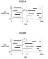
- FIG. 5A shows the availability of the GPS satellites 10 when a conventional positioning method is used.
- FIG. 5B shows the availability of the GPS satellites 10 when a positioning method according to an embodiment of the present invention is used.
- sections where lines are drawn denote where the GPS satellite 10 is available for the positioning calculation.
- GPS satellites 10 are at low elevation angles in a section "A" (three hours from 7 to 10) and are not available due to being masked by the low elevation angle.
- FIG. 6A shows a positioning accuracy when a conventional positioning method is used.
- FIG. 6B shows a positioning accuracy when a positioning method according to an embodiment of the present invention is used.
- a curve line showing the positioning accuracy upon using the GIM data only is drawn as a solid line.
- the other curve line drawn as a dash-dot line shows the positioning accuracy upon estimating ionospheric delay error " ⁇ I” from the first ionospheric delay error " ⁇ I 1 " and the second ionospheric delay error " ⁇ I 2 " (namely, both the GIM model and the Klobuchar model are used) according to an embodiment of the present invention as described above.
- the ionospheric delay error is estimated based on the GIM data, as shown in the solid line in FIG. 6B , highly accurate positioning information can be maintained because the GPS satellites 10 at low elevation angles can be used.
- the possitioning accuracy is degrated to some extent after time has has passed from the latest update of the GIM data (position at "0" scale on the horizontal axis) (see, for example, a section after 10 hours or longer has passed) because of the degradation of the reliability of the GIM data.
- the ionospheric delay is estimated based on the GIM data. Therefore, as shown in the curve in the dash-dot line in FIG. 6B , highly accurate positioning information can be maintained because the GPS satellites 10 even at low elevation angles in the section "A" can be used.
- the ionospheric delay error may be estimated by using the ionospheric model with the two-frequency data.
- ionospheric models two appropriate ionospheric models (GIM and Klobuchar models) based on the current GPS status are used.
- GIM and Klobuchar models two appropriate ionospheric models based on the current GPS status.
- any ionospheric model as a modification and substitution of the GIM or the Klobuchar model may also be used.
- the GIM data obtained by the external center 80 through the Internet are transferred to the vehicle 90.
- the GIM data obtained by a road-side facility through the Internet may be transferred to the vehicle 90 through road-to-vehicle communications, or the communicating section 70 itself of the vehicle 90 may directly access the Internet by wireless communications to directly obtain the GIM data.
Abstract

Description
- The present invention relates to a moving body positioning device for positioning a moving body by appropriately estimating an ionospheric delay error.
- Conventionally, there is a known technique for a satellite positioning system including a GPS receiver and a GPS server. In the technique, the GPS server receives ionospheric information intermittently transmitted based on events in the ionospheric layer such as sunrise, noon, and sunset, creates an ionospheric model, estimates ionospheric error, and supplies the information of the estimated ionospheric error to the GPS receiver (see, for example, Patent Document 1).
- Patent Document 1: Japanese Patent Application Publication No.
2005-517931 - On the other hand, various information items of ionospheric conditions for estimating the ionospheric error (such as a correction coefficient, an ionospheric model, and total electron content in the ionospheric layer) are available now. However, no proposal capable of appropriately utilizing the information by taking the included characteristics into account has been made.
- Therefore, an object of the present invention is to provide a moving body positioning device capable of appropriately using the various information items of ionospheric conditions, and accurately estimating and correcting for the ionospheric error.
- To achieve the above object, according to a first aspect of the present invention, there is provided a moving body positioning device including a first ionospheric state information receiving unit receiving information of a predicted ionospheric state at a time point later than a current time point; a second ionospheric state information receiving unit receiving information of an ionospheric state at the current time point; an ionospheric delay error estimating unit estimating an ionospheric delay error by correcting a first ionospheric delay error based on a second ionospheric delay error, the first ionospheric delay error being derived based on the first ionospheric state information, and the second ionospheric delay error being derived based on the second ionospheric state information; and a positioning unit locating a position of a moving body based on a received result of a radio wave from a satellite and the estimated ionospheric delay error.
- According to a second aspect of the present invention, there is provided a moving body positioning device according to the first aspect of the present invention, in which the ionospheric delay error estimating unit estimates the ionospheric delay error in a manner so that averaging is performed by applying a weighting coefficient to each of the first ionospheric delay error derived based on the first ionospheric state information and the second ionospheric delay error derived based on the second ionospheric state information.
- According to a third aspect of the present invention, there is provided a moving body positioning device according to the second aspect of the present invention, in which the weighting coefficient applied to the first ionospheric delay error varies depending on the elapsed time from when the first ionospheric state information is received, and a value of the weighting coefficient corresponding to a longer elapsed time is greater than a value of the weighting coefficient corresponding to a shorter elapsed time.
- According to a fourth aspect of the present invention, there is provided a moving body positioning device according to any one of the first through third aspects of the present invention, in which the first ionospheric state information is GIM (Global Ionosphere Map) data, and the second ionosphere state information is an ionospheric correction coefficient included in a navigation message.
- According to a fifth aspect of the present invention, there is provided a moving body positioning device according to the fourth aspect of the present invention, in which the first ionospheric state information receiving unit receives the GIM data from an external center.
- According to a sixth aspect of the present invention, there is provided a moving body positioning device according to the fourth aspect of the present invention, in which the second ionospheric delay error is derived by applying the ionospheric correction coefficient to a Klobuchar model.
- According to an embodiment of the present invention, there is provided a moving body positioning device capable of appropriately using the vaious information items of the ionospheric conditions, and accurately estimating and correcting for the ionospheric error.
-
-
FIG. 1 is a system configuration diagram showing a whole configuration of a GPS employing a moving body positioning device according to an embodiment of the present invention; -
FIG. 2 is a system configuration diagram showing an embodiment of aGPS receiver 1 mounted on avehicle 90 inFIG. 1 ; -
FIG. 3 is a drawing showing relationships between a world coordinate system and a local coordinate system; -
FIG. 4 is a drawing conceptually showing relationships between a first ionospheric delay error "ΔI1", a second ionospheric delay error "ΔI2", and an ionospheric delay error "ΔI"; -
FIG. 5A is a drawing conceptually showing availability ofGPS satellites 10 in a conventional positioning method; -
FIG. 5B is a drawing conceptually showing availability ofGPS satellites 10 in a positioning method according to an embodiment of the present invention; -
FIG. 6A is a drawing showing a positioning accuracy in a convetional positioning method; and -
FIG. 6B is a drawing showing a positioning accuracy in a positioning method according to an embodiment of the present invention. -
- 1:
- GPS receiver
- 10:
- GPS satellite
- 20:
- receiving section
- 30:
- filter
- 40:
- positioning calculating section
- 50:
- ionospheric delay error estimating section
- 60:
- satellite position calculating section
- 70:
- communicating section
- 80:
- external center
- 90:
- vehicle
- In the following, a best mode for carrying out the present invention is described with reference to the drawings.
-
FIG. 1 is a system configuration diagram showing a whole configuration of a GPS (Global Positioning System) employing a moving body positioning device according to an embodiment of the present invention. As shown inFIG. 1 , the GPS includesGPS satellites 10 orbiting around the earth and avehicle 90 positioned and movable on the earth. It should be noted that thevehicle 90 is merely an example of the moving bodies. The moving bodies include, but are not limited to, a two-wheel motor vehicle, a railroad car, a ship, a forklift, an automaton, and a cell phone movable in accordance with the movement of the owner. - The
GPS satellites 10 continuously broadcast a navigation message (a satellite signal) toward the earth. The navigation message includes satellite orbit information (ephemerides and almanac) of thecorresponding GPS satellite 10, a clock correction value, and a correction coefficient of the ionospheric layer. The navigation message is spread by a C/A code, carried on an L1 wave (frequency:1575.42 MHz), and continuously broadcasted toward the earth. It should be noted that the L1 wave is a composite wave of a sine wave modulated by the C/A code and a cosine wave modulated by a P code (Precision Code) and is orthogonally modulated. Each of the C/A code and the P code is a pseudo-noise code which is a code string containing "-1" and "1" each irregularly and periodically arranged. - It should be noted that, now, 24 GPS satellites orbit around the earth at an altitude of approximately 20,000 km and are arranged in six orbital planes inclined 55 degrees relative to each other so that 4 satellites are contained in each orbital plane. As a result, at least 5
GPS satellites 10 can be observed from any place on earth where the sky is open. - As a moving body position positioning device, a
GPS receiver 1 is mounted on thevehicle 90. TheGPS receiver 1 locates the position of thevehicle 90 based on satellite signals from theGPS satellites 10 as described below. -
FIG. 2 is a schematic system configuration diagram showing theGPS receiver 1 mounted on thevehicle 90 inFIG. 1 according to an embodiment of the present invention. InFIG. 2 , only one GPS satellite 101 (the subscript number represents a satellite number) is shown for illustrative purposes only. Herein, a signal processing of the satellite signal from theGPS satellite 101 is selectively described. Namely, the signal processing of the satellite signal from theGPS satellite 101 is substantially the same as that from any of the other GPS satellites such asGPS satellites GPS satellites - As shown in
FIG. 2 , theGPS receiver 1 in this embodiment includes, as main functional sections, a receivingsection 20, afilter 30, apositioning calculating section 40, an ionospheric delayerror estimating section 50, a satelliteposition calculating section 60, and a communicatingsection 70. - The receiving
section 20 receives a satellite signal from theGPS satellite 101 through aGPS antenna 22, performs a C/A code synchronization using an internally-generated replica C/A code, and extracts a navigation message. There may be various C/A code synchronization methods, and any appropriate method may be used. For example, a method of tracking a code phase where a peak correlation value of the replica C/A code with respect to the received C/A code is detected using DDL (Delay-Locked Loop). Whenever the navigation message is updated, the receivingsection 20 supplies an ionospheric correction coefficient included in the navigation message to the ionospheric delayerror estimating section 50. - Further, the receiving
section 20 calculates a pseudorange "ρ' " between theGPS satellite 101 and the vehicle 90 (accurately, the GPS receiver 1) based on a receiving result of the satellite signal from theGPS satellite 101. Unlike a true range between theGPS satellite 101 and thevehicle 90, the pseudorange "ρ' " includes clock bias and an error due to a variation in the radio wave propagation speed such as the ionospheric delay error. It should be noted that the symbol "'" added to the pseudorange "ρ " denotes that a filtering process described below is not yet performed. - Here, the pseudorange "ρ' " with respect to the
GPS satellite 101 may be calculated as follows:
where, the value "N" corresponds to the number of bits of the C/A code between theGPS satellite 101 and thevehicle 90 and is calculated based on a phase of the replica C/A code and a receiver's clock in theGPS receiver 1. It should be noted that the numerical value of "300" derives from a fact that one bit length of the C/A code is 1 µ s and a length corresponding to the 1 bit is approximately 300 m (1µ s × light speed). A signal representing the thus-calculated pseudorange "ρ'" is input to thefilter 30. - Further, the receiving
section 20 measures a carrier wave phase of the satellite signal and Doppler frequency change "Δf" of a Doppler-shifted received carrier wave using an internally-generated replica carrier. The Doppler frequency change "Δf" is measured as the difference (=fr-fc) between a replica carrier frequency "fr" and a known carrier frequency "fc" (1575.72 MHz). This function may be realized by PLL (Phase-Locked Loop) for calculating a correlation value using the replica carrier and tracking the receiving carrier. A signal representing the Doppler frequency change "Δf" is input to thefilter 30. - The
filter 30 performs a filtering process with respect to the pseudorange "ρ' " using the Doppler frequency change "Δf". In thefilter 30, the pseudorange "ρ" is derived after the filtering process using, for example, the following equation.
GPS satellite 101 and thevehicle 90 calculated by, for example, the following equation using the measured Doppler frequency change "Δf".
filter 30 may also be realized by using a filter, other than the Hatch filter shown in aboveExpression 1, such as a Kalman filter. A signal representing the pseudorange "ρ " after the filtering process is input to thepositioning calculating section 40. - The satellite
position calculating section 60 calculates a current position (X1, Y1, Z1) of theGPS satellite 101 in a global coordinate system based on satellite orbit information and the current time in the navigation message. It should be noted that since theGPS satellite 101 is one of the artificial satellites, the motion of theGPS satellite 101 is assumed to be within a certain plane (orbital plane) including the earth's gravitational center. Otherwise, the motion (orbit) of theGPS satellite 101 is assumed to be within an ellipse where the earth's center of gravity is one of the foci. Therefore, by performing numerical calculations based on Kepler's equation, the position of theGPS satellite 101 within the orbital plane can be calculated. Further, the position (X1, Y1, Z1) of theGPS satellite 101 can be obtained by performing a three-dimensional rotational coordinate conversion from the position of theGPS satellite 101 in the orbital plane by considering rotationally convertible relationships between the world coordinate system and the local coordinate system. It should be noted that, as shown inFIG. 3 , the world coordinate system is defined as a coordinate system having as the point of origin the earth's gravitational center, X and Y axes orthogonal to each other disposed in the equatorial plane and a Z axis orthogonal to each of the X and Y axes. A signal representing the satellite position (X1, Y1, Z1) is input to thepositioning calculating section 40. - The communicating
section 70 obtains global ionospheric distribution data, namely GIM (Global Ionosphere Map) data, from anexternal center 80 through anantenna 72. The GIM data are available from the University of Bern through the Internet. The GIM data include predicted ionospheric distribution data after a certain period of time (after one day) based on past ionospheric distribution data and ionospheric distribution data measured before. However, it is assumed that predicted ionospheric distribution data after a certain period of time are herein used. In this case, the communicatingsection 70 obtains the latest GIM data when, for example, theGPS receiver 1 is booted, and then may be operated so as to obtain the latest GIM data whenever the latest GIM data are updated (whenever the above certain period of time has elapsed) as long as theGPS receiver 1 continuously operates. The GIM data obtained by the communicatingsection 70 are supplied to the ionospheric delayerror estimating section 50. - The ionospheric delay
error estimating section 50 estimates the ionospheric delay error "ΔI" based on the GIM data from the communicatingsection 70 and the ionospheric correction coefficient from the receivingsection 20. The ionospheric delay error "ΔI" is caused by the change of the propagation speed of a radio wave due to a refraction index applied when the radio wave passes through the ionospheric layer. It is known that generally, the ionospheric delay error "ΔI" is proportional to a Total Electron Content (TEC) on the propagation path and is inversely proportional to the square of the carrier wave frequency. - Specifically, an ionospheric delay error estimation method may be realized as follows.
- First, the ionospheric delay
error estimating section 50 estimates the ionospheric delay error based on the GIM data. In the following, the thus-obtained ionospheric delay error based on the GIM data is called "first ionospheric delay error "ΔI1"". The first ionospheric delay error "ΔI1" is highly accuare but has a characteristic that the reliability is degraded as time passes because of long update intervals of the GIM data (for example, once a day). - On the other hand, the ionospheric delay
error estimating section 50 estimates a vertical delay amount at a positioning point (position of the vehicle 90) by applying the ionospheric correction coefficient to a previously provided ionospheric model (typically a Klobuchar model). Next, the ionospheric delayerror estimating section 50 derives a delay amount in the slant-range direction (corresponding to the ionospheric delay error) by considering the elevation angle of the GPS satellite 101 (satellite elevation angle) with respect to the vertical delay amount. In the following, the ionospheric delay error estimated based on the ionospheric correction coefficient from the receivingsection 20 is called "second ionospheric delay error "Δ I2"". The accuracy of the second ionospheric delay error "ΔI2" is less than that of the first ionospheric delay error "ΔI1" but the second ionospheric delay error "AI2" has a characteristic of having an excellent real-time property because the ionospheric correction coefficient generated based on a current status of the ionospheric layer is included in the navigation message. It should be noted that the Klobuchar model is described in, for example, J. Klobuchar "Design and characteristics of the GPS ionospheric time delay algorithm for single frequency users", Proc. Position Location and Navigation Symposium, 1986", but any modified model based on this model may also be used. - The ionospheric delay
error estimating section 50 estimates the ionospheric delay error "ΔI" by integrating the first ionospheric delay error "ΔI1" and the second ionospheric delay error "ΔI2" derived from models independent of each other as described above. This integration may be realized based on, for example, the following formula.


FIG. 4 , as the elapsed time from the latest update of the GIM data until the current time point increases, the weighting with respect to the first ionospheric delay error "ΔI1" is reduced and the weighting with respect to the second ionospheric delay error "ΔI2" is increased. This is due to the consideration that the update interval of the GIM data is long and the reliablity of the first ionospheric delay error "ΔI1" is degraded as time passes from the update but the reliablity of the second ionospheric delay error "ΔI2" is hardly degraded as time passes because of depending on real-time information. It should be noted that in the Formula (1), the "α " continuously decreases as time passes from the latest update of the GIM data until now. However, any Formula where the "α " discontinuously decreases as time passes from the latest update of the GIM data until the current time point may also be used. A signal representing the thus-derived ionospheric delay error "ΔI" is input to thepositioning calculating section 40. - The
positioning calculating section 40 locates a position (Xu, Yu, Zu) of thevehicle 90 based on the calculation result of the satellite position, the ionospheric delay error "ΔI", and the pseudorange "ρ" from the receivingsection 20. Specifically, the following equation may be used.
GPS satellite 101. However, the same equation may also be applied to the otherobservable satellites 10. The position of thevehicle 90 may be derived by assigning each ionospheric delay error "ΔI" estimated as described above with respect to the corresponding threeGPS satellits 10 to the "ΔI" in Formula (2) of the corresponding threeGPS satellites 10 and using each pseudorange "ρ" and each satellite position obtained with respect to the corresponding threeGPS satellites 10 and the principle of triangulation. In this case, as described above, the pseudorange "ρ" includes the clock bias, which is removed by using the pseudorange "ρ", the ionospheric delay error "ΔI", and the satellite position each obtained with respect to afourth GPS satellite 10. - A positioning interval by the
positioning calculating section 40 may be, for example, an observation interval (for example, 1 ms) or a prescribed observation interval (for example, 50 ms or 100 ms). A positioning result is supplied to, for example, a navigation system (not shown). - Next, the usefulness of an ionospheric delay error estimation method according to the above described embodiment of the present invention is described with reference to conceptual drawings.
-
FIG. 5A shows the availability of theGPS satellites 10 when a conventional positioning method is used.FIG. 5B shows the availability of theGPS satellites 10 when a positioning method according to an embodiment of the present invention is used. InFIGS. 5A and 5B , sections where lines are drawn denote where theGPS satellite 10 is available for the positioning calculation. - In a case of the conventional method (without using GIM data), as shown in
FIG. 5A ,many GPS satellites 10 are at low elevation angles in a section "A" (three hours from 7 to 10) and are not available due to being masked by the low elevation angle. - On the other hand, according to the embodiment of the present invention, as shown in
FIG. 5B ,many GPS satellites 10 are at low elevation angles in the section "A", but a positioning process can be performed by using the satellite signal from theGPS satellites 10 at low elevation angles. This means that since the ionospheric delay error can be estimated and corrected using the GIM data, highly accurate positioning information can be maintained even when the elevation angles is low where the ionospheric delay error becomes larger. -
FIG. 6A shows a positioning accuracy when a conventional positioning method is used.FIG. 6B shows a positioning accuracy when a positioning method according to an embodiment of the present invention is used. InFIG. 6B , as reference, a curve line showing the positioning accuracy upon using the GIM data only is drawn as a solid line. The other curve line drawn as a dash-dot line shows the positioning accuracy upon estimating ionospheric delay error "ΔI" from the first ionospheric delay error "ΔI1" and the second ionospheric delay error "ΔI2" (namely, both the GIM model and the Klobuchar model are used) according to an embodiment of the present invention as described above. - In a case of the conventional method (without using GIM data) as shown in
FIG. 6A , the positioning accuracy in the section "A" inFIG. 5A is largely degraded because ofunusable GPS satellites 10 at low elevation angles. - Further, when the ionospheric delay error is estimated based on the GIM data, as shown in the solid line in
FIG. 6B , highly accurate positioning information can be maintained because theGPS satellites 10 at low elevation angles can be used. However, in this case, as shown by the solid line inFIG 6B , the possitioning accuracy is degrated to some extent after time has has passed from the latest update of the GIM data (position at "0" scale on the horizontal axis) (see, for example, a section after 10 hours or longer has passed) because of the degradation of the reliability of the GIM data. - On the other hand, in a case of the embodiment of the present invention, the ionospheric delay is estimated based on the GIM data. Therefore, as shown in the curve in the dash-dot line in
FIG. 6B , highly accurate positioning information can be maintained because theGPS satellites 10 even at low elevation angles in the section "A" can be used. Further, even after time has passed from the latest update of the GIM data (position at "0" scale on the horizontal axis) (see, for example, a section after 10 hours or more has passed), by using both the first ionospheric delay error "ΔI1" and the second ionospheric delay error "ΔI2" (most preferably, by increasing the weighing with respect to the second ionospheric delay error "ΔI2" as time passes), the degradation of the positioning accuracy due to the degradation of the reliability of the GIM data over time is better controlled. - As described above, according to an embodiment of the present invention, especially the following excellent advantages may be obtained.
- As described above, by effectively using the advantages of the GIM data and the Klobuchar model at the same time, while highly accurate positioning information using the
GPS satellites 10 at low elevation angle is being maintained, the degradation of the positioning accuracy that may have occurred after a long time has passed since updating the GIM data is better controlled. - A preferred embodiment of the present invention is described above. However, the present invention is not limited to the embodiment described above. It should be understood that various modifications and substitutions may be made without departing from the scope of the present invention.
- For example, when the
GPS receiver 1 is a two-frequency receiver capable of receiving both L1 wave and L2 wave, the ionospheric delay error may be estimated by using the ionospheric model with the two-frequency data. - Further, in the above embodiment, two appropriate ionospheric models (GIM and Klobuchar models) based on the current GPS status are used. However, in the future when ionospheric models each having the same characteristics are available, it becomes possible to alternatively use those ionospheric models in the same manner as described above. Still further, any ionospheric model as a modification and substitution of the GIM or the Klobuchar model may also be used.
- Further, in the above embodiment, the GIM data obtained by the
external center 80 through the Internet are transferred to thevehicle 90. However any other configuration may also be used. For example, the GIM data obtained by a road-side facility through the Internet may be transferred to thevehicle 90 through road-to-vehicle communications, or the communicatingsection 70 itself of thevehicle 90 may directly access the Internet by wireless communications to directly obtain the GIM data. - The present application claims priority from Japanese Patent Application No.
2006-333675 filed on December 11, 2006
Claims (6)
- A moving body positioning device comprising:a first ionospheric state information receiving unit receiving information of a predicted ionospheric state at a time point later than a current time point;a second ionospheric state information receiving unit receiving information of an ionospheric state at the current time point;an ionospheric delay error estimating unit estimating an ionospheric delay error by correcting a first ionospheric delay error based on a second ionospheric delay error, the first ionospheric delay error being derived based on the first ionospheric state information, and the second ionospheric delay error being derived based on the second ionospheric state information; anda positioning unit locating a position of a moving body based on a received result of a radio wave from a satellite and the estimated ionospheric delay error.
- The moving body positioning device according to claim 1, wherein
the ionospheric delay error estimating unit estimates the ionospheric delay error in a manner so that averaging is performed by applying a weighting coefficient to each of the first ionospheric delay error derived based on the first ionospheric state information and the second ionospheric delay error derived based on the second ionospheric state information. - The moving body positioning device according to claim 2, wherein
the weighting coefficient applied to the first ionospheric delay error varies depending on an elapsed time from when the first ionospheric state information is received, and a value of the weighting coefficient corresponding to a longer elapsed time is greater than a value of the weighting coefficient corresponding to a shorter elapsed time. - The moving body positioning device according to any one of claims 1 through 3, wherein
the first ionospheric state information is GIM (Global Ionosphere Map) data, and the second ionosphere state information is an ionospheric correction coefficient included in a navigation message. - The moving body positioning device according to claims 4, wherein
the first ionospheric state information receiving unit receives the GIM data from an external center. - The moving body positioning device according to claims 4, wherein
the second ionospheric delay error is derived by applying the ionospheric correction coefficient to a Klobuchar model.
Applications Claiming Priority (2)
| Application Number | Priority Date | Filing Date | Title |
|---|---|---|---|
| JP2006333675A JP4103926B1 (en) | 2006-12-11 | 2006-12-11 | Positioning device for moving objects |
| PCT/JP2007/072776 WO2008072463A1 (en) | 2006-12-11 | 2007-11-26 | Mobile unit positioning device |
Publications (3)
| Publication Number | Publication Date |
|---|---|
| EP2056121A1 true EP2056121A1 (en) | 2009-05-06 |
| EP2056121A4 EP2056121A4 (en) | 2012-01-18 |
| EP2056121B1 EP2056121B1 (en) | 2013-05-22 |
Family
ID=39511488
Family Applications (1)
| Application Number | Title | Priority Date | Filing Date |
|---|---|---|---|
| EP07832501.6A Expired - Fee Related EP2056121B1 (en) | 2006-12-11 | 2007-11-26 | Mobile unit positioning device |
Country Status (6)
| Country | Link |
|---|---|
| US (1) | US7994973B2 (en) |
| EP (1) | EP2056121B1 (en) |
| JP (1) | JP4103926B1 (en) |
| KR (1) | KR101046552B1 (en) |
| CN (1) | CN101535833B (en) |
| WO (1) | WO2008072463A1 (en) |
Cited By (1)
| Publication number | Priority date | Publication date | Assignee | Title |
|---|---|---|---|---|
| RU2486544C2 (en) * | 2010-10-22 | 2013-06-27 | Всеволод Борисович Иванов | Method of determining consumer coordinates in glonass/gps systems and apparatus for realising said method |
Families Citing this family (12)
| Publication number | Priority date | Publication date | Assignee | Title |
|---|---|---|---|---|
| FR2977314B1 (en) * | 2011-06-29 | 2013-07-12 | Ixblue | NAVIGATION DEVICE AND METHOD INTEGRATING MULTIPLE INERTIAL HYBRID NAVIGATION SYSTEMS |
| JP2013145168A (en) * | 2012-01-13 | 2013-07-25 | Denso Corp | Angular velocity error correction device of gyro for vehicle |
| KR101222468B1 (en) * | 2012-11-02 | 2013-01-15 | 한국 천문 연구원 | Gnss hardware bias calculating system and method |
| US9612340B1 (en) * | 2013-02-25 | 2017-04-04 | Apple Inc. | Systems, methods, devices and subassemblies for creating and delivering crowd-sourced GNSS models |
| KR101607082B1 (en) | 2015-03-05 | 2016-04-11 | 국방과학연구소 | System and method of ionospheric delay estimation for extending the coverage of differential satellite navigation |
| DE102017202901A1 (en) * | 2017-02-23 | 2018-08-23 | Robert Bosch Gmbh | Method for determining an adaptive model of an electron density distribution |
| JP6946761B2 (en) * | 2017-06-08 | 2021-10-06 | 株式会社デンソー | Positioning device |
| DE102018202225A1 (en) * | 2018-02-14 | 2019-08-14 | Robert Bosch Gmbh | Method and apparatus for providing raw correction data for correcting atmospheric disturbances for satellite navigation, and method and apparatus for determining correction data for correcting atmospheric disturbances for satellite navigation |
| DE102018206788A1 (en) * | 2018-05-03 | 2019-11-07 | Robert Bosch Gmbh | Method and device for checking ionosphere correction parameters for satellite navigation for a vehicle |
| JP7267691B2 (en) * | 2018-07-20 | 2023-05-02 | 株式会社日立製作所 | Mobile positioning system and mobile positioning method |
| CN113671534A (en) * | 2020-05-15 | 2021-11-19 | 华为技术有限公司 | Positioning compensation method, vehicle-mounted unit, medium and system |
| CN112666578A (en) * | 2020-12-16 | 2021-04-16 | 中国人民解放军61081部队 | Two-way timing algorithm and calculating device considering orbit error and ionospheric delay |
Citations (4)
| Publication number | Priority date | Publication date | Assignee | Title |
|---|---|---|---|---|
| US5428358A (en) * | 1994-05-03 | 1995-06-27 | The United States Of America As Represented By The Secretary Of The Navy | Apparatus and method for ionospheric mapping |
| WO1997039433A2 (en) * | 1996-04-01 | 1997-10-23 | Tci International, Inc. | Method and apparatus for real-time ionospheric mapping and dynamic forecasting |
| JP2005517931A (en) * | 2002-02-13 | 2005-06-16 | サーフ テクノロジー インコーポレイテッド | Prediction and correction of ionospheric errors in satellite positioning systems. |
| US20060262010A1 (en) * | 2005-05-20 | 2006-11-23 | C/O Nec Toshiba Space Systems, Ltd. | GPSR multi-frequency measuring device, corrective method and program for ionospheric delay |
Family Cites Families (10)
| Publication number | Priority date | Publication date | Assignee | Title |
|---|---|---|---|---|
| US5323322A (en) * | 1992-03-05 | 1994-06-21 | Trimble Navigation Limited | Networked differential GPS system |
| JPH07198821A (en) | 1994-01-06 | 1995-08-01 | Japan Radio Co Ltd | Gps receivr and its positoning method |
| US6531981B1 (en) * | 2000-05-01 | 2003-03-11 | Skynetix, Llc | Global augmentation to global positioning system |
| US6407700B1 (en) * | 2000-12-05 | 2002-06-18 | Agilent Technologies, Inc. | Method and apparatus for autonomously measuring ionospheric delay and single-frequency, GPS time receiver incorporating same |
| JP2002318271A (en) | 2001-04-23 | 2002-10-31 | Japan Radio Co Ltd | Method for estimating ionospheric delay |
| FR2849209B1 (en) * | 2002-12-19 | 2007-04-06 | Agence Spatiale Europeenne | METHOD AND SYSTEM FOR REAL-TIME NAVIGATION USING THREE-CARRIER SATELLITE-TYPE RADIO ELECTRIC SIGNALS AND IONOSPHERIC CORRECTIONS |
| JP2005077291A (en) * | 2003-09-02 | 2005-03-24 | Nippon Gps Solutions Corp | Three-dimensional positioning system |
| WO2006073490A2 (en) * | 2004-07-23 | 2006-07-13 | California Institute Of Technology | Generating high precision ionospheric ground-truth measurements |
| JP2006333675A (en) | 2005-05-30 | 2006-12-07 | Seiko Epson Corp | Motor controlling method and its device |
| JP5165846B2 (en) * | 2006-01-16 | 2013-03-21 | 古野電気株式会社 | Positioning arithmetic unit and ionospheric delay calculation method |
-
2006
- 2006-12-11 JP JP2006333675A patent/JP4103926B1/en not_active Expired - Fee Related
-
2007
- 2007-11-26 KR KR1020097005560A patent/KR101046552B1/en active IP Right Grant
- 2007-11-26 EP EP07832501.6A patent/EP2056121B1/en not_active Expired - Fee Related
- 2007-11-26 CN CN2007800428953A patent/CN101535833B/en not_active Expired - Fee Related
- 2007-11-26 WO PCT/JP2007/072776 patent/WO2008072463A1/en active Application Filing
- 2007-11-26 US US12/377,400 patent/US7994973B2/en not_active Expired - Fee Related
Patent Citations (4)
| Publication number | Priority date | Publication date | Assignee | Title |
|---|---|---|---|---|
| US5428358A (en) * | 1994-05-03 | 1995-06-27 | The United States Of America As Represented By The Secretary Of The Navy | Apparatus and method for ionospheric mapping |
| WO1997039433A2 (en) * | 1996-04-01 | 1997-10-23 | Tci International, Inc. | Method and apparatus for real-time ionospheric mapping and dynamic forecasting |
| JP2005517931A (en) * | 2002-02-13 | 2005-06-16 | サーフ テクノロジー インコーポレイテッド | Prediction and correction of ionospheric errors in satellite positioning systems. |
| US20060262010A1 (en) * | 2005-05-20 | 2006-11-23 | C/O Nec Toshiba Space Systems, Ltd. | GPSR multi-frequency measuring device, corrective method and program for ionospheric delay |
Non-Patent Citations (1)
| Title |
|---|
| See also references of WO2008072463A1 * |
Cited By (1)
| Publication number | Priority date | Publication date | Assignee | Title |
|---|---|---|---|---|
| RU2486544C2 (en) * | 2010-10-22 | 2013-06-27 | Всеволод Борисович Иванов | Method of determining consumer coordinates in glonass/gps systems and apparatus for realising said method |
Also Published As
| Publication number | Publication date |
|---|---|
| KR20090057258A (en) | 2009-06-04 |
| JP2008145303A (en) | 2008-06-26 |
| JP4103926B1 (en) | 2008-06-18 |
| CN101535833B (en) | 2012-03-21 |
| KR101046552B1 (en) | 2011-07-05 |
| EP2056121B1 (en) | 2013-05-22 |
| US20100225536A1 (en) | 2010-09-09 |
| WO2008072463A1 (en) | 2008-06-19 |
| US7994973B2 (en) | 2011-08-09 |
| CN101535833A (en) | 2009-09-16 |
| EP2056121A4 (en) | 2012-01-18 |
Similar Documents
| Publication | Publication Date | Title |
|---|---|---|
| EP2056121B1 (en) | Mobile unit positioning device | |
| US7978127B2 (en) | Mobile unit positioning device | |
| Capuano et al. | Feasibility study of GNSS as navigation system to reach the Moon | |
| US8682581B2 (en) | Vehicle navigation using non-GPS LEO signals and on-board sensors | |
| CN109313272B (en) | Improved GNSS receiver using velocity integration | |
| EP2558885B1 (en) | Software global navigation satellite systems receiver for high-altitude spacecraft applications | |
| CN1942776B (en) | Method of tracking radio frequency signals | |
| US8035554B2 (en) | Device for measuring a position of a mobile station | |
| EP1221586A2 (en) | Position and heading error-correction method and apparatus for vehicle navigation systems | |
| US20080111738A1 (en) | Method and apparatus in standalone positioning without broadcast ephemeris | |
| WO2005062070A9 (en) | Method and system for a data interface for aiding a satellite positioning system receiver | |
| US10194269B2 (en) | Systems and methods for using doppler measurements to estimate a position of a receiver | |
| JP4905054B2 (en) | Mobile satellite radio receiver | |
| KR101638210B1 (en) | Method for optimising an acquisition of a spread-spectrum signal from a satellite by a mobile receiver | |
| KR100922937B1 (en) | Apparatus and method for calculating satellite acquisition information to measure position of mobile station | |
| KR102172145B1 (en) | Tightly-coupled localization method and apparatus in dead-reckoning system | |
| JP5163511B2 (en) | GNSS receiver and positioning method | |
| Karaim | Ultra-tight GPS/INS integrated system for land vehicle navigation in challenging environments | |
| JP2000266836A (en) | Method for compensating for gps multipath | |
| JP2009098099A (en) | Positioning device for mobile body | |
| JP2008232761A (en) | Positioning device for mobile | |
| JP2010112759A (en) | Mobile body positioning apparatus | |
| JP4470944B2 (en) | Mobile positioning device | |
| JP4400330B2 (en) | Position detection apparatus and position detection method | |
| JP4518096B2 (en) | Mobile positioning device |
Legal Events
| Date | Code | Title | Description |
|---|---|---|---|
| PUAI | Public reference made under article 153(3) epc to a published international application that has entered the european phase |
Free format text: ORIGINAL CODE: 0009012 |
|
| 17P | Request for examination filed |
Effective date: 20090213 |
|
| AK | Designated contracting states |
Kind code of ref document: A1 Designated state(s): AT BE BG CH CY CZ DE DK EE ES FI FR GB GR HU IE IS IT LI LT LU LV MC MT NL PL PT RO SE SI SK TR |
|
| AX | Request for extension of the european patent |
Extension state: AL BA HR MK RS |
|
| RBV | Designated contracting states (corrected) |
Designated state(s): AT BE BG CH CY CZ DE DK EE ES FI FR GB GR HU IE IS IT LI LT LU LV MC MT NL PL PT RO SE SI SK TR |
|
| DAX | Request for extension of the european patent (deleted) | ||
| RBV | Designated contracting states (corrected) |
Designated state(s): DE FR |
|
| REG | Reference to a national code |
Ref country code: DE Ref legal event code: R079 Ref document number: 602007030675 Country of ref document: DE Free format text: PREVIOUS MAIN CLASS: G01S0005140000 Ipc: G01S0019230000 |
|
| A4 | Supplementary search report drawn up and despatched |
Effective date: 20111220 |
|
| RIC1 | Information provided on ipc code assigned before grant |
Ipc: G01S 19/23 20100101AFI20111214BHEP |
|
| GRAP | Despatch of communication of intention to grant a patent |
Free format text: ORIGINAL CODE: EPIDOSNIGR1 |
|
| RAP1 | Party data changed (applicant data changed or rights of an application transferred) |
Owner name: TOYOTA JIDOSHA KABUSHIKI KAISHA |
|
| GRAS | Grant fee paid |
Free format text: ORIGINAL CODE: EPIDOSNIGR3 |
|
| GRAA | (expected) grant |
Free format text: ORIGINAL CODE: 0009210 |
|
| AK | Designated contracting states |
Kind code of ref document: B1 Designated state(s): DE FR |
|
| REG | Reference to a national code |
Ref country code: DE Ref legal event code: R082 Ref document number: 602007030675 Country of ref document: DE Representative=s name: KUHNEN & WACKER PATENT- UND RECHTSANWALTSBUERO, DE Ref country code: DE Ref legal event code: R083 Ref document number: 602007030675 Country of ref document: DE |
|
| REG | Reference to a national code |
Ref country code: DE Ref legal event code: R096 Ref document number: 602007030675 Country of ref document: DE Effective date: 20130718 |
|
| PLBE | No opposition filed within time limit |
Free format text: ORIGINAL CODE: 0009261 |
|
| STAA | Information on the status of an ep patent application or granted ep patent |
Free format text: STATUS: NO OPPOSITION FILED WITHIN TIME LIMIT |
|
| 26N | No opposition filed |
Effective date: 20140225 |
|
| REG | Reference to a national code |
Ref country code: DE Ref legal event code: R097 Ref document number: 602007030675 Country of ref document: DE Effective date: 20140225 |
|
| REG | Reference to a national code |
Ref country code: DE Ref legal event code: R084 Ref document number: 602007030675 Country of ref document: DE |
|
| REG | Reference to a national code |
Ref country code: DE Ref legal event code: R084 Ref document number: 602007030675 Country of ref document: DE Effective date: 20140910 |
|
| REG | Reference to a national code |
Ref country code: FR Ref legal event code: PLFP Year of fee payment: 9 |
|
| REG | Reference to a national code |
Ref country code: FR Ref legal event code: PLFP Year of fee payment: 10 |
|
| REG | Reference to a national code |
Ref country code: FR Ref legal event code: PLFP Year of fee payment: 11 |
|
| REG | Reference to a national code |
Ref country code: FR Ref legal event code: PLFP Year of fee payment: 12 |
|
| PGFP | Annual fee paid to national office [announced via postgrant information from national office to epo] |
Ref country code: DE Payment date: 20211005 Year of fee payment: 15 Ref country code: FR Payment date: 20211109 Year of fee payment: 15 |
|
| REG | Reference to a national code |
Ref country code: DE Ref legal event code: R119 Ref document number: 602007030675 Country of ref document: DE |
|
| PG25 | Lapsed in a contracting state [announced via postgrant information from national office to epo] |
Ref country code: DE Free format text: LAPSE BECAUSE OF NON-PAYMENT OF DUE FEES Effective date: 20230601 |
|
| PG25 | Lapsed in a contracting state [announced via postgrant information from national office to epo] |
Ref country code: FR Free format text: LAPSE BECAUSE OF NON-PAYMENT OF DUE FEES Effective date: 20221130 |