EP2055948A1 - Procédé de contrôle de pompe hydraulique commutée cycliquement - Google Patents
Procédé de contrôle de pompe hydraulique commutée cycliquement Download PDFInfo
- Publication number
- EP2055948A1 EP2055948A1 EP08016531A EP08016531A EP2055948A1 EP 2055948 A1 EP2055948 A1 EP 2055948A1 EP 08016531 A EP08016531 A EP 08016531A EP 08016531 A EP08016531 A EP 08016531A EP 2055948 A1 EP2055948 A1 EP 2055948A1
- Authority
- EP
- European Patent Office
- Prior art keywords
- pumping
- time
- stroke
- fluid
- cylinder
- Prior art date
- Legal status (The legal status is an assumption and is not a legal conclusion. Google has not performed a legal analysis and makes no representation as to the accuracy of the status listed.)
- Granted
Links
Images


Classifications
-
- F—MECHANICAL ENGINEERING; LIGHTING; HEATING; WEAPONS; BLASTING
- F01—MACHINES OR ENGINES IN GENERAL; ENGINE PLANTS IN GENERAL; STEAM ENGINES
- F01B—MACHINES OR ENGINES, IN GENERAL OR OF POSITIVE-DISPLACEMENT TYPE, e.g. STEAM ENGINES
- F01B25/00—Regulating, controlling, or safety means
- F01B25/02—Regulating or controlling by varying working-fluid admission or exhaust, e.g. by varying pressure or quantity
- F01B25/08—Final actuators
- F01B25/10—Arrangements or adaptations of working-fluid admission or discharge valves
-
- F—MECHANICAL ENGINEERING; LIGHTING; HEATING; WEAPONS; BLASTING
- F01—MACHINES OR ENGINES IN GENERAL; ENGINE PLANTS IN GENERAL; STEAM ENGINES
- F01B—MACHINES OR ENGINES, IN GENERAL OR OF POSITIVE-DISPLACEMENT TYPE, e.g. STEAM ENGINES
- F01B25/00—Regulating, controlling, or safety means
- F01B25/02—Regulating or controlling by varying working-fluid admission or exhaust, e.g. by varying pressure or quantity
-
- F—MECHANICAL ENGINEERING; LIGHTING; HEATING; WEAPONS; BLASTING
- F04—POSITIVE - DISPLACEMENT MACHINES FOR LIQUIDS; PUMPS FOR LIQUIDS OR ELASTIC FLUIDS
- F04B—POSITIVE-DISPLACEMENT MACHINES FOR LIQUIDS; PUMPS
- F04B11/00—Equalisation of pulses, e.g. by use of air vessels; Counteracting cavitation
- F04B11/005—Equalisation of pulses, e.g. by use of air vessels; Counteracting cavitation using two or more pumping pistons
-
- F—MECHANICAL ENGINEERING; LIGHTING; HEATING; WEAPONS; BLASTING
- F04—POSITIVE - DISPLACEMENT MACHINES FOR LIQUIDS; PUMPS FOR LIQUIDS OR ELASTIC FLUIDS
- F04B—POSITIVE-DISPLACEMENT MACHINES FOR LIQUIDS; PUMPS
- F04B49/00—Control, e.g. of pump delivery, or pump pressure of, or safety measures for, machines, pumps, or pumping installations, not otherwise provided for, or of interest apart from, groups F04B1/00 - F04B47/00
- F04B49/06—Control using electricity
-
- F—MECHANICAL ENGINEERING; LIGHTING; HEATING; WEAPONS; BLASTING
- F04—POSITIVE - DISPLACEMENT MACHINES FOR LIQUIDS; PUMPS FOR LIQUIDS OR ELASTIC FLUIDS
- F04B—POSITIVE-DISPLACEMENT MACHINES FOR LIQUIDS; PUMPS
- F04B49/00—Control, e.g. of pump delivery, or pump pressure of, or safety measures for, machines, pumps, or pumping installations, not otherwise provided for, or of interest apart from, groups F04B1/00 - F04B47/00
- F04B49/22—Control, e.g. of pump delivery, or pump pressure of, or safety measures for, machines, pumps, or pumping installations, not otherwise provided for, or of interest apart from, groups F04B1/00 - F04B47/00 by means of valves
- F04B49/24—Bypassing
- F04B49/243—Bypassing by keeping open the inlet valve
-
- F—MECHANICAL ENGINEERING; LIGHTING; HEATING; WEAPONS; BLASTING
- F04—POSITIVE - DISPLACEMENT MACHINES FOR LIQUIDS; PUMPS FOR LIQUIDS OR ELASTIC FLUIDS
- F04B—POSITIVE-DISPLACEMENT MACHINES FOR LIQUIDS; PUMPS
- F04B7/00—Piston machines or pumps characterised by having positively-driven valving
- F04B7/0076—Piston machines or pumps characterised by having positively-driven valving the members being actuated by electro-magnetic means
-
- F—MECHANICAL ENGINEERING; LIGHTING; HEATING; WEAPONS; BLASTING
- F04—POSITIVE - DISPLACEMENT MACHINES FOR LIQUIDS; PUMPS FOR LIQUIDS OR ELASTIC FLUIDS
- F04B—POSITIVE-DISPLACEMENT MACHINES FOR LIQUIDS; PUMPS
- F04B2201/00—Pump parameters
- F04B2201/06—Valve parameters
- F04B2201/0601—Opening times
-
- F—MECHANICAL ENGINEERING; LIGHTING; HEATING; WEAPONS; BLASTING
- F04—POSITIVE - DISPLACEMENT MACHINES FOR LIQUIDS; PUMPS FOR LIQUIDS OR ELASTIC FLUIDS
- F04B—POSITIVE-DISPLACEMENT MACHINES FOR LIQUIDS; PUMPS
- F04B2205/00—Fluid parameters
- F04B2205/09—Flow through the pump
-
- F—MECHANICAL ENGINEERING; LIGHTING; HEATING; WEAPONS; BLASTING
- F04—POSITIVE - DISPLACEMENT MACHINES FOR LIQUIDS; PUMPS FOR LIQUIDS OR ELASTIC FLUIDS
- F04B—POSITIVE-DISPLACEMENT MACHINES FOR LIQUIDS; PUMPS
- F04B2205/00—Fluid parameters
- F04B2205/13—Pressure pulsations after the pump
Definitions
- the invention relates to a method of operating a fluid working machine, comprising at least one working chamber of cyclically changing volume, a high pressure fluid connection, a low pressure fluid connection and at least one electrically actuated valve connecting said working chamber to said high pressure fluid connection and/or said low pressure fluid connection, wherein the pumping and/or motoring strokes of said working chamber are controlled by an appropriate actuation of said electrically actuated valve, wherein the actuation of said electrically actuated valve is modified by a time evolvement function, taking into account the time evolvement of the fluid flow demand on the high-pressure side and/or the time evolvement of said working chamber's pumping/motoring strokes.
- the invention further relates to a fluid working machine, comprising at least one working chamber of cyclically changing volume, a high pressure fluid connection, a low pressure fluid connection, at least one electrically actuated valve connecting said working chamber to a said high pressure fluid connection and/or said low pressure fluid connection and at least an electronic controller unit.
- fluid working machines are generally used, when fluids are to be pumped or fluids are used to drive the fluid working machine in a motoring mode.
- the word "fluid” can relate to both gases and liquids.
- fluid can even relate to a mixture of gas and liquid and furthermore to a supercritical fluid, where no distinction between gas and liquid can be made anymore.
- such fluid working machines are used, if the pressure level of a fluid has to be increased.
- a fluid working machine could be an air compressor or a hydraulic pump.
- fluid working machines comprise one or more working chambers of a cyclically changing volume.
- a fluid inlet valve and a fluid outlet valve are provided for each cyclically changing volume.
- the fluid inlet valves and the fluid outlet valves are passive valves.
- its fluid inlet valve opens, while its fluid outlet valve closes, due to the pressure differences, caused by the volume increase of the working chamber.
- the fluid inlet valve closes, while the fluid outlet valve opens due to the changed pressure differences.
- a relatively new and promising approach for improving fluid working machines is the so-called "synthetically commutated hydraulic pumps", also known as “digital displacement pumps”. These pumps are a subset of variable displacement pumps.
- Such synthetically commutated hydraulic pumps are known, for example, from EP 0 494 236 B1 or WO 91/05163 A1 .
- the passive inlet valves are replaced by electrically actuated inlet valves.
- the passive fluid outlet valves are also replaced by electrically actuated outlet valves.
- a full-stroke pumping mode, an empty cycle mode (idle mode) and a part stroke pumping mode can be achieved.
- the pump can be used as a hydraulic motor as well. If the pump is run as a hydraulic motor, full stroke motoring and part-stroke motoring is possible, as well.
- a major advantage of such synthetically commutated hydraulic pumps is their higher efficiency, as compared to traditional hydraulic pumps. Furthermore, because the valves are electrically actuated, the output characteristics of a synthetically commutated hydraulic pump can be changed very quickly.
- the synthetically commutated hydraulic pump It is possible to switch the synthetically commutated hydraulic pump to a full pumping mode for a certain time for example.
- a high pressure fluid reservoir is filled with fluid.
- the synthetically commutated hydraulic pump is switched to an idle mode and the fluid flow demand is supplied by the high pressure fluid reservoir.
- the synthetically commutated hydraulic pump is switched on again.
- a fluid flow demand is used as the (main) input parameter.
- the displacement demand is expressed as a certain percentage of the maximum displacement of the fluid working machine.
- the displacement demand is given by e. g. the position of a command (e. g. joy stick, pedal, throttle or the like), operated by an operator.
- the displacement demand which is expressed as a certain percentage of the maximum displacement of the fluid working machine is considered by using the so-called "accumulator" variable.
- the accumulator sums up the demand in a variable, used in an electronic controller unit, controlling the operation of the fluid working machine. As soon as a certain threshold level of the accumulator has been reached, a pumping cycle of the next following working chamber is initiated and the accumulator is decreased by an amount, corresponding to the volume to be pumped.
- the time evolvement function comprises a vectorised variable, being indicative of the time dependency of the fluid output flow during a pumping stroke.
- the use of a time evolvement function, comprising a vectorised variable can be done in a way, such that a given demand is satisfied at an earlier time than usual, preferably at the earliest sensible moment. Satisfying the demand at an earlier time will allow more flexibility for future decisions. If a certain demand is already satisfied at time t - ⁇ t, as compared to time t in conventional systems, an increased demand can already be satisfied at time t. In conventional systems, one had to wait until time t + ⁇ t.
- a pumping cycle needs some time to be completed, once it is initiated. This means, as a consequence, that a working chamber, being involved with a pumping cycle, is no longer available for additional pumping until the respective working cycle is completed. Therefore, it may actually be problematic, to start a full stroke pumping cycle, because the respective cylinder will be blocked for a full revolution of the fluid working machine.
- a given demand can very often be satisfied in another way as well. For example, if a six cylinder pump with equally spaced cylinders is used as a fluid working machine, a 100 % demand can be satisfied by initiating a full-stroke pumping cycle.
- the two or three previous cylinders which already started their contraction cycle, to satisfy the 100 % demand.
- This can be done by using the first cylinder with its remaining contractable volume of 25 % and the second cylinder with its 75 % remaining contractable volume for part stroke pumping. Both remaining contractable volumes add up to 100 %. This will leave the actual cylinder for a possible future increase in fluid flow demand.
- knowledge about the time evolvement of the cylinder's pumping ability can be used as well to avoid pressure peaks, by excluding certain stroke patterns of the cylinders.
- the decision of whether to initiate a pumping stroke or not can depend on one or on several fields of the vector.
- the update of the vectorised variable can comprise adding or subtracting a value to/from one or several fields. Furthermore, it can comprise a shifting of one or several fields of the vectorised variable. If more fields ("dimensions" or phases) are used for the vectorised variable, the accuracy and the time responsiveness of the pump can be enhanced. However, the enhancement can become negligible at some point. This point normally depends on the actual application. Furthermore, the workload of updating the vectorised variable can increase to an undesirable level. Therefore, a good compromise should be chosen for each individual application.
- the fluid flow demand normally comes as an input from an operator, operating the machinery, in which the fluid working machine is installed.
- the fluid flow demand can be derived from the position of a command (e. g. a command lever, a paddle, a throttle, a joystick, the engine speed or the like).
- a command e. g. a command lever, a paddle, a throttle, a joystick, the engine speed or the like.
- the fluid flow demand is determined by an electronic controller, for example.
- the electronic controller determines (or influences) the fluid flow demand only under certain working conditions. This could be, for example, a shutdown under critical working conditions, or a reduction in power, because there is a risk of engine overheating.
- a preferred embodiment can be realised if the time evolvement function is able to trigger a pumping/ motoring stroke for a plurality of working chambers and/or at a plurality of phases of each working chamber's working cycle.
- the pumping/motoring stroke is of course an active one.
- the decision of whether to initiate a pumping stroke or not, and about the displacement fraction to be chosen was done slightly before the bottom dead centre of the respective cylinder and only for this single cylinder.
- it is not only suggested to trigger a pumping stroke i. e. to make a decision about a pumping stroke
- the decision can also be done during a continuos time interval. This can increase the responsiveness of the pump and can decrease pressure pulses.
- the time evolvement function comprises a spacing function, so that successive pumping/motoring strokes are spaced in time in a way to smooth the fluid output flow to said high pressure fluid manifold.
- this should be done for the peak output phases of successive pumping/ motoring strokes.
- a very simple implementation could be, for example, that the initiation of a part stroke pumping cycle is prohibited, during the high peak fluid output phase of a certain working chamber.
- this exclusion can be done, if the part stroke would be around a 50 % fractional value, because it would start during a phase of very high fluid flow output of the previous working chamber.
- pumping work that could in principle be performed at an earlier time, is moved slightly backwards in time. However, the avoidance of pressure pulsations can overweight this slight disadvantage.
- the time evolvement function comprises a variable being indicative of a fluid flow demand, wherein a threshold level of said variable is chosen in a way that a pumping/ motoring stroke is initiated in advance of the actual demand.
- a threshold level of said variable is chosen in a way that a pumping/ motoring stroke is initiated in advance of the actual demand.
- an accumulator this could be realised by setting the threshold level to a level lower than the percentage of the pumping cycle that will be initiated. For example, an accumulator value of 50 % could initiate a full stroke pumping cycle (100 % stroke). This, of course, can imply, that the accumulator can have negative values.
- the threshold level can be chosen, depending on the demand, i. e. the slope of the accumulator. Using this embodiment, one might still suffer from certain imperfections. But it has the advantage, that it can be easily implemented with existing synthetically commutated hydraulic pumps.
- a plurality of electrically actuated valves are controlled using the suggested method.
- the respective electrically actuated valves are connected to different working chambers of the fluid working machine.
- the advantages of the present invention will be even more predominant.
- the responsiveness of the pump can be increased, while the pressure pulses can be further decreased.
- the pumping/motoring strokes in particular the initiation of the pumping/motoring strokes of the working chambers are out of phase to each other.
- the respective bottom dead centre of each working chamber is reached at a different point in time, when the fluid working machine is revolving or moving.
- this does not exclude that in a hydraulic pump/motor, comprising several banks of cylinders, the pumping/motoring strokes of corresponding working chambers are initiated at the same time, respectively.
- the object of the invention is also solved, if a fluid working machine, comprising at least one working chamber of cyclically changing volume, a high pressure fluid connection, a low pressure fluid connection, at least one electrically actuated valve connecting said working chamber to said high pressure fluid connection and/or said low pressure fluid connection and at least an electronic controller unit is built in a way, that the electronic controller unit comprises a time evolvement consideration means that is designed and arranged in a way, that the electronic controller unit performs a method according to at least one of the previously described embodiments of the invention. If a plurality of working chambers is present, a high-pressure fluid manifold and/or a low pressure fluid manifold can be used.
- FIG. 1 an example of a synthetically commutated hydraulic pump 1, with one bank 2, having six cylinders 3 is shown.
- Each cylinder has a working space 4 of a cyclically changing volume.
- the working spaces 4 are essentially defined by a cylinder part 5 and a piston 6.
- a spring 7 pushes the cylinder part 5 and the piston 6 apart from each other.
- the pistons 6 are supported by the eccentrics 8, which are attached off-centre of the rotating axis of the same rotatable shaft 9.
- multiple pistons can also share the same eccentric 8.
- the orbiting movement of the eccentric 8 causes the pistons 6 to reciprocally move in and out of the respective cylinder parts 5. By this movement of the pistons 6 within the cylinder parts 5, the volume of the working spaces 4 is cyclically changing.
- the synthetically commutated hydraulic pump 1 is of a type with electrically actuated inlet valves 10 and electrically actuated outlet valves 11. Both inlet valves 10 and outlet valves 11 are fluidly connected to the working chambers 4 of the cylinders 3 on one side. On the other side, the valves are fluidly connected to a low pressure fluid manifold 20 and a high pressure fluid manifold 19, respectively.
- the synthetically commutated hydraulic pump 1 has electrically actuated outlet valves 11, the synthetically commutated hydraulic pump 1 can be used as a hydraulic motor as well.
- the design could be different from the example shown in Fig. 1 .
- several banks 2 of cylinders 3 could be provided for.
- one or several banks 2 show a different number of cylinders 3, for example four, five, seven and eight cylinders.
- the cylinders 3 are equally spaced within a full revolution of the shaft 9 (i.e. 60° out of phase to each other), the cylinders 3 could be spaced unevenly, as well.
- Another possible modification is achieved, if the number of cylinders in different banks 2 of the synthetically commutated hydraulic pump 1 differ from each other.
- one bank 2 might comprise six cylinders 3, while a second bank 2 of the synthetically commutated hydraulic pump 1 comprises just three cylinders 3.
- different cylinders can show different displacements.
- the cylinders of one bank 2 could show a higher displacement, as compared to the displacement of the cylinders of another bank.
- a valve which is used as a fluid inlet valve 10 in the pumping mode will become a fluid outlet valve in the motoring mode and vice versa.
- piston and cylinder pumps are possible. Instead, other types of pumps can take advantage of the invention as well.
- Fig. 2 gives an overview of the fluid flow output of a single cylinder 3 towards the high pressure side.
- the fluid flow output 12 is depicted for several modes a - e.
- the ordinate shows the fluid flow output
- the abscissa shows the time.
- the time is expressed as the rotating angle of the rotable shaft 9. Assuming a constant speed, angle and time are proportional to each other. Each tick on the abscissa represents an angle of 30°.
- a full revolution of the rotable shaft 9 is indicated by R.
- a full revolution R comprises two phases, namely a volume contraction phase I and a volume expansion phase II.
- DP 1 indicates the so-called bottom dead centre of the cylinder 3
- DP 7 indicates the top dead centre of the cylinder 3.
- a zero stroke pumping mode (idle mode) is shown.
- the synthetically commutated hydraulic pump 1 is in an idle mode.
- the inlet valve 10 then remains open all the time. Hydraulic fluid is therefore sucked into the working chamber 4 via the inlet valve 10 during the volume expansion phase II.
- hydraulic fluid is pushed out of the working chamber 4 back into the fluid inlet manifold 20 via the same path, i. e. through inlet valve 10. Therefore, no effective pumping (i. e. no pumping towards the high pressure fluid manifold 19) is performed in zero stroke mode (idle mode).
- Fig. 2 e the 100 % stroke (full stroke) pumping mode is shown.
- the inlet valve 10 is moved to its closed position right at DP 1, i. e. the bottom dead centre of the cylinder 3. Therefore, during volume contraction phase I, pressure builds up within the working chamber 4 and eventually fluid outlet valve 11 will open under the resulting pressure difference, so that the fluid flow output will be expelled towards the high pressure fluid manifold 19. This is indicated by the hatched area under curve 12.
- DP 7 top dead center
- the fluid inlet valve 10 will be opened again.
- This pumping behaviour is equivalent to traditional hydraulic pumps with two passive valves.
- synthetically commutated hydraulic pumps offer more possibilities:
- a 25 % stroke mode is shown.
- the fluid inlet valve 10 remains open during the volume contraction phase I. Therefore, the fluid flow output 12 is first expelled towards the low pressure manifold 20. This is indicated by the white area under curve 12.
- the fluid inlet valve 10 is closed.
- pressure builds up in the contracting volume chamber 4
- fluid outlet valve 11 will open under the resulting pressure difference and the fluid flow output 12 is expelled towards the high pressure fluid manifold 19. This is indicated by the hatched area under curve 12.
- the effective fluid flow output towards the high pressure fluid manifold 19 is about 25 % of the total volume contraction of the working chamber 4.
- the fluid inlet valve 10 is opened again.
- a 50 % stroke mode ( Fig. 2 c) and a 75 % stroke mode ( Fig. 2 d) can be realised. It should be noted, that it is also possible, to realise any displacement fraction in-between, by appropriately selecting the closing time of the inlet valve 10 (also known as firing angle, firing time, closing angle) of the respective cylinder 3.
- Fig. 3 illustrates, how the different cylinders 3 of the synthetically commutated hydraulic pump 1 work together. For brevity, only two modes are shown. In Fig. 3 a) , a zero stroke mode is shown (see Fig. 2 a) , while in Fig. 3 b) a 25 % stroke mode is shown (see Fig. 2 b ).
- the controller decided only at one single point in time for only one cylinder about the opening and closing of the inlet valve 3: The decision was made at the bottom dead centre of the respective cylinder 3 (in reality slightly before that time, to take into account the closing time of inlet valve 10). Therefore, the decision on whether to close inlet valve 10 of cylinder No. 1 at all, and at what time the closing has to be done (determining the volume fraction to be pumped to the high pressure side) is made at DP 1, the bottom dead centre of cylinder No. 1. Likewise, the decision for cylinder No. 2 was made at the bottom dead centre of cylinder No. 2, i. e. at DP 3; the decision about cylinder No. 3 at the bottom dead centre of cylinder No. 3, i. e. at DP 5, and so on.
- a decision will be made at the time, when the demand changes, i. e. at DP 4 in this example.
- DP 4 it is realised, that cylinder No. 1 has not yet reached the point, that is not able anymore to provide a displacement fraction of 25 %.
- the respective borderline is DP 5.
- the proposed algorithm will use the earliest (sensible) point in time, that is possible, and will therefore decide to use cylinder No. 1 for pumping. Therefore, at DP 5 the inlet valve 10 of cylinder No. 1 is closed and the pumping will be performed.
- the time delay between fluid flow demand change and the delivery of a high pressure fluid flow amounts only to an angle of 30° in the given example.
- cylinder No. 1 is not (yet) actuated, and can still be used for performing additional pumping work.
- Another advantage of the multiple decision performed at DP 1 is, that the output fluid flow reaction is faster as compared to an actuation of the inlet valve 10 of cylinder No. 1.
- cylinder No. 1 will output some fluid starting with DP 1, its fluid flow output is still quite low in the time interval between DP 1 and DP 3 (indicated by the shaded area), and amounts to only 25 % of the requested flow demand.
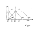
- Fig. 5 to 7 a different aspect of the invention will be explained.
- the fluid flow demand 15 is set to 35 %.
- the development of the value of the accumulator 14 as well as the fluid flow output 13 is shown.
- the graph for the accumulator 14 shows the first dimension for the three dimensional accumulator vector.
- the suggested algorithms can, however, be equally employed using part-stroke cycles as well.
- Fig. 5 the conventional algorithm is depicted.
- the accumulator variable 14 builds up and as soon as 100 % is reached, a pumping pulse is initiated and the accumulator 14 is decreased by 100 %.
- the demand 15 is 35 %, it is slightly higher than the time average of 33 %, which is an output of a series of two idle strokes and a full stroke, following repeatedly after each other. Therefore, at some point a series of two pulses with only one idle stroke in-between is performed once in a while, yielding the overall fluid output 13 of a three-tip spike 16. It has to be noted, that the three-tip spike 16 takes quite some time to develop. This is equivalent to a time delay in the response toward a given fluid flow demand.
- the mentioned time delay can be addressed by simply changing the threshold value.
- the threshold level is set to 40 %.
- different values could be used as well.
- T the modified threshold level
- Another modification is the introduction of a vector instead of a scale for the accumulator.
- the vectorial accumulator can be three-dimensional.
- the three-dimension represents the sequence of the fluid flow output of the pumping cylinder.
- 25 % of the volume fraction is pumped.
- time interval B 50 % of the total volume fraction is pumped, and in time interval C the last 25 % of the volume fraction is pumped, although the length of the time intervals A, B, C is the same. This is due to the sinusoidal shape of the movement of piston 6 within cylinder part 5.
- the vector (-25, -50, - 25), representing the time dependant fluid flow output of the respective cylinder will be added to the accumulator vector.
- the first dimension always represents the actual time interval. Therefore, when modifying the accumulator vector at each decision point, the number within each register will have to be shifted, to represent the advancement in time.
- the fluid flow output is shown in Fig. 7 .
- the accumulator curve 14, shown in Fig. 7 represents the first register of the accumulator vector, i. e. the number representing the actual time interval.
- the time response is faster, as compared to the state of the art, as well: the first pumping stroke is initiated 60° degrees earlier than it is the case in Fig. 5 .
- the three-tip spike 17 occurs earlier as in Fig. 5 , as well.
- Another advantage of employing an accumulator vector is, that the time development of a pumping cycle is automatically considered. By the shifting of the vectorial registers, which represent the advancement in time, there is a tendency to smooth the fluid flow output.
- the accumulator vector can have a different dimension as well.
- Fig. 9 the algorithm according to the state of the art is used. As can be seen from Fig. 9 , once the accumulator has overcome the threshold level of 100 %, a full-stroke pumping cycle is initiated (the individual fluid output flows of the single cylinders is indicated by a dashed line 17). At the decision point, following immediately after the decision point, where the full-stroke pumping cycle has been initiated, the accumulator 14 will be updated to a value of 45 %. Hence, a part-stroke pumping cycle is initiated during the high output flow phase of the full-stroke pumping cycle (compared to Fig. 8 , interval B). This results in a very strong peak 18 of the total fluid flow output 13.
- the spacing function is implemented as a simple condition. If a full-stroke pumping cycle is in its peak fluid output flow phase (see interval B in Fig. 8 ), no part-stroke pumping cycle will be initiated. This will lead to a much smoother total fluid output flow 13.
Priority Applications (1)
| Application Number | Priority Date | Filing Date | Title |
|---|---|---|---|
| EP08016531A EP2055948B1 (fr) | 2007-11-01 | 2008-09-19 | Procédé de contrôle de pompe hydraulique commutée cycliquement |
Applications Claiming Priority (5)
| Application Number | Priority Date | Filing Date | Title |
|---|---|---|---|
| EP07254337A EP2055946A1 (fr) | 2007-11-01 | 2007-11-01 | Procédé de fonctionnement de machine de travail pour fluides |
| EP07254331.7A EP2055943B1 (fr) | 2007-11-01 | 2007-11-01 | Procédé pour la commande d'une machine de travail pour fluides |
| EP07254332.5A EP2055944B1 (fr) | 2007-11-01 | 2007-11-01 | Procédé de contrôle de pompe hydraulique commutée cycliquement |
| EP07254333.3A EP2055945B8 (fr) | 2007-11-01 | 2007-11-01 | Procédé pour la commande d'une machine de travail pour fluides |
| EP08016531A EP2055948B1 (fr) | 2007-11-01 | 2008-09-19 | Procédé de contrôle de pompe hydraulique commutée cycliquement |
Publications (2)
| Publication Number | Publication Date |
|---|---|
| EP2055948A1 true EP2055948A1 (fr) | 2009-05-06 |
| EP2055948B1 EP2055948B1 (fr) | 2010-07-21 |
Family
ID=39789968
Family Applications (4)
| Application Number | Title | Priority Date | Filing Date |
|---|---|---|---|
| EP08016530A Active EP2055947B1 (fr) | 2007-11-01 | 2008-09-19 | Procédé de contrôle de pompe hydraulique commutée cycliquement |
| EP08016532A Ceased EP2055949A1 (fr) | 2007-11-01 | 2008-09-19 | Procédé de fonctionnement de machine de travail pour fluides |
| EP08016531A Active EP2055948B1 (fr) | 2007-11-01 | 2008-09-19 | Procédé de contrôle de pompe hydraulique commutée cycliquement |
| EP08016533.5A Active EP2055950B1 (fr) | 2007-11-01 | 2008-09-19 | Procédé de contrôle de pompe hydraulique commutée cycliquement |
Family Applications Before (2)
| Application Number | Title | Priority Date | Filing Date |
|---|---|---|---|
| EP08016530A Active EP2055947B1 (fr) | 2007-11-01 | 2008-09-19 | Procédé de contrôle de pompe hydraulique commutée cycliquement |
| EP08016532A Ceased EP2055949A1 (fr) | 2007-11-01 | 2008-09-19 | Procédé de fonctionnement de machine de travail pour fluides |
Family Applications After (1)
| Application Number | Title | Priority Date | Filing Date |
|---|---|---|---|
| EP08016533.5A Active EP2055950B1 (fr) | 2007-11-01 | 2008-09-19 | Procédé de contrôle de pompe hydraulique commutée cycliquement |
Country Status (3)
| Country | Link |
|---|---|
| EP (4) | EP2055947B1 (fr) |
| AT (2) | ATE475013T1 (fr) |
| DE (2) | DE602008001855D1 (fr) |
Families Citing this family (6)
| Publication number | Priority date | Publication date | Assignee | Title |
|---|---|---|---|---|
| CN103038508B (zh) | 2010-02-23 | 2016-08-17 | 阿尔特弥斯智能动力有限公司 | 流体工作机器和运行流体工作机器的方法 |
| CN103038507B (zh) | 2010-02-23 | 2016-04-06 | 阿尔特弥斯智能动力有限公司 | 流体工作机器的阀门定时 |
| GB2477997B (en) * | 2010-02-23 | 2015-01-14 | Artemis Intelligent Power Ltd | Fluid working machine and method for operating fluid working machine |
| FI123459B (fi) | 2011-05-05 | 2013-05-15 | Teknologian Tutkimuskeskus Vtt | Menetelmä kohteen pinnan muokkaamiseksi |
| AU2018204487B1 (en) * | 2017-11-10 | 2019-05-30 | Quantum Servo Pumping Technologies Pty Ltd | Pumping systems |
| EP3674546B1 (fr) | 2018-12-28 | 2022-07-13 | Artemis Intelligent Power Limited | Synchronisation de soupape dans une machine hydraulique commutée électroniquement |
Citations (3)
| Publication number | Priority date | Publication date | Assignee | Title |
|---|---|---|---|---|
| US4321014A (en) | 1979-12-31 | 1982-03-23 | Polaroid Corporation | Constant flow pumping apparatus |
| WO1991005163A1 (fr) | 1988-09-29 | 1991-04-18 | The University Of Edinburgh | Machine a fonctionnement fluidique ameliore |
| EP1537333B1 (fr) | 2002-09-12 | 2006-06-14 | Artemis Intelligent Power Ltd. | Machine de travail fluidique et methode d'utilisation |
Family Cites Families (1)
| Publication number | Priority date | Publication date | Assignee | Title |
|---|---|---|---|---|
| GB8822901D0 (en) * | 1988-09-29 | 1988-11-02 | Mactaggart Scot Holdings Ltd | Apparatus & method for controlling actuation of multi-piston pump &c |
-
2008
- 2008-09-19 EP EP08016530A patent/EP2055947B1/fr active Active
- 2008-09-19 AT AT08016530T patent/ATE475013T1/de not_active IP Right Cessation
- 2008-09-19 DE DE602008001855T patent/DE602008001855D1/de active Active
- 2008-09-19 EP EP08016532A patent/EP2055949A1/fr not_active Ceased
- 2008-09-19 AT AT08016531T patent/ATE475014T1/de not_active IP Right Cessation
- 2008-09-19 EP EP08016531A patent/EP2055948B1/fr active Active
- 2008-09-19 DE DE602008001854T patent/DE602008001854D1/de active Active
- 2008-09-19 EP EP08016533.5A patent/EP2055950B1/fr active Active
Patent Citations (4)
| Publication number | Priority date | Publication date | Assignee | Title |
|---|---|---|---|---|
| US4321014A (en) | 1979-12-31 | 1982-03-23 | Polaroid Corporation | Constant flow pumping apparatus |
| WO1991005163A1 (fr) | 1988-09-29 | 1991-04-18 | The University Of Edinburgh | Machine a fonctionnement fluidique ameliore |
| EP0494236B1 (fr) | 1988-09-29 | 1995-12-13 | Artemis Intelligent Power Ltd. | Machine a fonctionnement fluidique ameliore |
| EP1537333B1 (fr) | 2002-09-12 | 2006-06-14 | Artemis Intelligent Power Ltd. | Machine de travail fluidique et methode d'utilisation |
Also Published As
| Publication number | Publication date |
|---|---|
| EP2055947A1 (fr) | 2009-05-06 |
| EP2055948B1 (fr) | 2010-07-21 |
| DE602008001854D1 (de) | 2010-09-02 |
| EP2055950B1 (fr) | 2017-04-12 |
| EP2055947B1 (fr) | 2010-07-21 |
| EP2055950A1 (fr) | 2009-05-06 |
| ATE475014T1 (de) | 2010-08-15 |
| EP2055949A1 (fr) | 2009-05-06 |
| DE602008001855D1 (de) | 2010-09-02 |
| ATE475013T1 (de) | 2010-08-15 |
Similar Documents
| Publication | Publication Date | Title |
|---|---|---|
| EP2055944B1 (fr) | Procédé de contrôle de pompe hydraulique commutée cycliquement | |
| EP2055945B1 (fr) | Procédé pour la commande d'une machine de travail pour fluides | |
| EP2055943B1 (fr) | Procédé pour la commande d'une machine de travail pour fluides | |
| EP2055948B1 (fr) | Procédé de contrôle de pompe hydraulique commutée cycliquement | |
| JP5373072B2 (ja) | 流体作動機械および方法 | |
| WO2009056137A1 (fr) | Procédé de fonctionnement d'une machine à fluide | |
| EP2246565B1 (fr) | Procédé pour exploiter une machine fluidique | |
| JP6701216B2 (ja) | スラリー媒体を取り扱うための油圧ポンプシステム |
Legal Events
| Date | Code | Title | Description |
|---|---|---|---|
| PUAI | Public reference made under article 153(3) epc to a published international application that has entered the european phase |
Free format text: ORIGINAL CODE: 0009012 |
|
| AK | Designated contracting states |
Kind code of ref document: A1 Designated state(s): AT BE BG CH CY CZ DE DK EE ES FI FR GB GR HR HU IE IS IT LI LT LU LV MC MT NL NO PL PT RO SE SI SK TR |
|
| AX | Request for extension of the european patent |
Extension state: AL BA MK RS |
|
| GRAP | Despatch of communication of intention to grant a patent |
Free format text: ORIGINAL CODE: EPIDOSNIGR1 |
|
| 17P | Request for examination filed |
Effective date: 20091028 |
|
| AKX | Designation fees paid |
Designated state(s): AT BE BG CH CY CZ DE DK EE ES FI FR GB GR HR HU IE IS IT LI LT LU LV MC MT NL NO PL PT RO SE SI SK TR |
|
| GRAS | Grant fee paid |
Free format text: ORIGINAL CODE: EPIDOSNIGR3 |
|
| GRAA | (expected) grant |
Free format text: ORIGINAL CODE: 0009210 |
|
| AK | Designated contracting states |
Kind code of ref document: B1 Designated state(s): AT BE BG CH CY CZ DE DK EE ES FI FR GB GR HR HU IE IS IT LI LT LU LV MC MT NL NO PL PT RO SE SI SK TR |
|
| REG | Reference to a national code |
Ref country code: GB Ref legal event code: FG4D |
|
| REG | Reference to a national code |
Ref country code: CH Ref legal event code: EP |
|
| REG | Reference to a national code |
Ref country code: IE Ref legal event code: FG4D |
|
| REF | Corresponds to: |
Ref document number: 602008001855 Country of ref document: DE Date of ref document: 20100902 Kind code of ref document: P |
|
| RAP2 | Party data changed (patent owner data changed or rights of a patent transferred) |
Owner name: ARTEMIS INTELLIGENT POWER LTD Owner name: SAUER-DANFOSS APS |
|
| REG | Reference to a national code |
Ref country code: NL Ref legal event code: VDEP Effective date: 20100721 |
|
| REG | Reference to a national code |
Ref country code: GB Ref legal event code: 732E Free format text: REGISTERED BETWEEN 20101118 AND 20101124 |
|
| LTIE | Lt: invalidation of european patent or patent extension |
Effective date: 20100721 |
|
| PG25 | Lapsed in a contracting state [announced via postgrant information from national office to epo] |
Ref country code: AT Free format text: LAPSE BECAUSE OF FAILURE TO SUBMIT A TRANSLATION OF THE DESCRIPTION OR TO PAY THE FEE WITHIN THE PRESCRIBED TIME-LIMIT Effective date: 20100721 Ref country code: FI Free format text: LAPSE BECAUSE OF FAILURE TO SUBMIT A TRANSLATION OF THE DESCRIPTION OR TO PAY THE FEE WITHIN THE PRESCRIBED TIME-LIMIT Effective date: 20100721 Ref country code: LT Free format text: LAPSE BECAUSE OF FAILURE TO SUBMIT A TRANSLATION OF THE DESCRIPTION OR TO PAY THE FEE WITHIN THE PRESCRIBED TIME-LIMIT Effective date: 20100721 Ref country code: NL Free format text: LAPSE BECAUSE OF FAILURE TO SUBMIT A TRANSLATION OF THE DESCRIPTION OR TO PAY THE FEE WITHIN THE PRESCRIBED TIME-LIMIT Effective date: 20100721 Ref country code: NO Free format text: LAPSE BECAUSE OF FAILURE TO SUBMIT A TRANSLATION OF THE DESCRIPTION OR TO PAY THE FEE WITHIN THE PRESCRIBED TIME-LIMIT Effective date: 20101021 |
|
| PG25 | Lapsed in a contracting state [announced via postgrant information from national office to epo] |
Ref country code: CY Free format text: LAPSE BECAUSE OF FAILURE TO SUBMIT A TRANSLATION OF THE DESCRIPTION OR TO PAY THE FEE WITHIN THE PRESCRIBED TIME-LIMIT Effective date: 20100721 Ref country code: BG Free format text: LAPSE BECAUSE OF FAILURE TO SUBMIT A TRANSLATION OF THE DESCRIPTION OR TO PAY THE FEE WITHIN THE PRESCRIBED TIME-LIMIT Effective date: 20101021 Ref country code: SI Free format text: LAPSE BECAUSE OF FAILURE TO SUBMIT A TRANSLATION OF THE DESCRIPTION OR TO PAY THE FEE WITHIN THE PRESCRIBED TIME-LIMIT Effective date: 20100721 Ref country code: PL Free format text: LAPSE BECAUSE OF FAILURE TO SUBMIT A TRANSLATION OF THE DESCRIPTION OR TO PAY THE FEE WITHIN THE PRESCRIBED TIME-LIMIT Effective date: 20100721 Ref country code: IS Free format text: LAPSE BECAUSE OF FAILURE TO SUBMIT A TRANSLATION OF THE DESCRIPTION OR TO PAY THE FEE WITHIN THE PRESCRIBED TIME-LIMIT Effective date: 20101121 Ref country code: HR Free format text: LAPSE BECAUSE OF FAILURE TO SUBMIT A TRANSLATION OF THE DESCRIPTION OR TO PAY THE FEE WITHIN THE PRESCRIBED TIME-LIMIT Effective date: 20100721 |
|
| PG25 | Lapsed in a contracting state [announced via postgrant information from national office to epo] |
Ref country code: GR Free format text: LAPSE BECAUSE OF FAILURE TO SUBMIT A TRANSLATION OF THE DESCRIPTION OR TO PAY THE FEE WITHIN THE PRESCRIBED TIME-LIMIT Effective date: 20101022 Ref country code: LV Free format text: LAPSE BECAUSE OF FAILURE TO SUBMIT A TRANSLATION OF THE DESCRIPTION OR TO PAY THE FEE WITHIN THE PRESCRIBED TIME-LIMIT Effective date: 20100721 Ref country code: SE Free format text: LAPSE BECAUSE OF FAILURE TO SUBMIT A TRANSLATION OF THE DESCRIPTION OR TO PAY THE FEE WITHIN THE PRESCRIBED TIME-LIMIT Effective date: 20100721 Ref country code: BE Free format text: LAPSE BECAUSE OF FAILURE TO SUBMIT A TRANSLATION OF THE DESCRIPTION OR TO PAY THE FEE WITHIN THE PRESCRIBED TIME-LIMIT Effective date: 20100721 |
|
| PG25 | Lapsed in a contracting state [announced via postgrant information from national office to epo] |
Ref country code: MC Free format text: LAPSE BECAUSE OF NON-PAYMENT OF DUE FEES Effective date: 20100930 Ref country code: DK Free format text: LAPSE BECAUSE OF FAILURE TO SUBMIT A TRANSLATION OF THE DESCRIPTION OR TO PAY THE FEE WITHIN THE PRESCRIBED TIME-LIMIT Effective date: 20100721 |
|
| PLBE | No opposition filed within time limit |
Free format text: ORIGINAL CODE: 0009261 |
|
| STAA | Information on the status of an ep patent application or granted ep patent |
Free format text: STATUS: NO OPPOSITION FILED WITHIN TIME LIMIT |
|
| PG25 | Lapsed in a contracting state [announced via postgrant information from national office to epo] |
Ref country code: EE Free format text: LAPSE BECAUSE OF FAILURE TO SUBMIT A TRANSLATION OF THE DESCRIPTION OR TO PAY THE FEE WITHIN THE PRESCRIBED TIME-LIMIT Effective date: 20100721 Ref country code: IT Free format text: LAPSE BECAUSE OF FAILURE TO SUBMIT A TRANSLATION OF THE DESCRIPTION OR TO PAY THE FEE WITHIN THE PRESCRIBED TIME-LIMIT Effective date: 20100721 Ref country code: RO Free format text: LAPSE BECAUSE OF FAILURE TO SUBMIT A TRANSLATION OF THE DESCRIPTION OR TO PAY THE FEE WITHIN THE PRESCRIBED TIME-LIMIT Effective date: 20100721 Ref country code: CZ Free format text: LAPSE BECAUSE OF FAILURE TO SUBMIT A TRANSLATION OF THE DESCRIPTION OR TO PAY THE FEE WITHIN THE PRESCRIBED TIME-LIMIT Effective date: 20100721 Ref country code: SK Free format text: LAPSE BECAUSE OF FAILURE TO SUBMIT A TRANSLATION OF THE DESCRIPTION OR TO PAY THE FEE WITHIN THE PRESCRIBED TIME-LIMIT Effective date: 20100721 |
|
| 26N | No opposition filed |
Effective date: 20110426 |
|
| PG25 | Lapsed in a contracting state [announced via postgrant information from national office to epo] |
Ref country code: ES Free format text: LAPSE BECAUSE OF FAILURE TO SUBMIT A TRANSLATION OF THE DESCRIPTION OR TO PAY THE FEE WITHIN THE PRESCRIBED TIME-LIMIT Effective date: 20101101 |
|
| REG | Reference to a national code |
Ref country code: FR Ref legal event code: TP |
|
| PG25 | Lapsed in a contracting state [announced via postgrant information from national office to epo] |
Ref country code: IE Free format text: LAPSE BECAUSE OF NON-PAYMENT OF DUE FEES Effective date: 20100919 |
|
| REG | Reference to a national code |
Ref country code: DE Ref legal event code: R097 Ref document number: 602008001855 Country of ref document: DE Effective date: 20110426 |
|
| PG25 | Lapsed in a contracting state [announced via postgrant information from national office to epo] |
Ref country code: MT Free format text: LAPSE BECAUSE OF FAILURE TO SUBMIT A TRANSLATION OF THE DESCRIPTION OR TO PAY THE FEE WITHIN THE PRESCRIBED TIME-LIMIT Effective date: 20100721 |
|
| PG25 | Lapsed in a contracting state [announced via postgrant information from national office to epo] |
Ref country code: LU Free format text: LAPSE BECAUSE OF NON-PAYMENT OF DUE FEES Effective date: 20100919 Ref country code: HU Free format text: LAPSE BECAUSE OF FAILURE TO SUBMIT A TRANSLATION OF THE DESCRIPTION OR TO PAY THE FEE WITHIN THE PRESCRIBED TIME-LIMIT Effective date: 20110122 |
|
| PG25 | Lapsed in a contracting state [announced via postgrant information from national office to epo] |
Ref country code: TR Free format text: LAPSE BECAUSE OF FAILURE TO SUBMIT A TRANSLATION OF THE DESCRIPTION OR TO PAY THE FEE WITHIN THE PRESCRIBED TIME-LIMIT Effective date: 20100721 |
|
| REG | Reference to a national code |
Ref country code: CH Ref legal event code: PL |
|
| PG25 | Lapsed in a contracting state [announced via postgrant information from national office to epo] |
Ref country code: LI Free format text: LAPSE BECAUSE OF NON-PAYMENT OF DUE FEES Effective date: 20120930 Ref country code: PT Free format text: LAPSE BECAUSE OF NON-PAYMENT OF DUE FEES Effective date: 20100721 Ref country code: CH Free format text: LAPSE BECAUSE OF NON-PAYMENT OF DUE FEES Effective date: 20120930 |
|
| REG | Reference to a national code |
Ref country code: FR Ref legal event code: CD Owner name: DANFOSS POWER SOLUTIONS APS, DK Effective date: 20140527 |
|
| REG | Reference to a national code |
Ref country code: DE Ref legal event code: R082 Ref document number: 602008001855 Country of ref document: DE Representative=s name: NESTLER, JAN HENDRIK, DIPL.-PHYS.UNIV. DR.RER., DE |
|
| REG | Reference to a national code |
Ref country code: DE Ref legal event code: R082 Ref document number: 602008001855 Country of ref document: DE Representative=s name: NESTLER, JAN HENDRIK, DIPL.-PHYS.UNIV. DR.RER., DE Effective date: 20140702 Ref country code: DE Ref legal event code: R081 Ref document number: 602008001855 Country of ref document: DE Owner name: DANFOSS POWER SOLUTIONS APS, DK Free format text: FORMER OWNER: ARTEMIS INTELLIGENT POWER LTD., SAUER-DANFOSS APS, , DK Effective date: 20140702 Ref country code: DE Ref legal event code: R081 Ref document number: 602008001855 Country of ref document: DE Owner name: ARTEMIS INTELLIGENT POWER LTD., GB Free format text: FORMER OWNER: ARTEMIS INTELLIGENT POWER LTD., SAUER-DANFOSS APS, , DK Effective date: 20140702 Ref country code: DE Ref legal event code: R081 Ref document number: 602008001855 Country of ref document: DE Owner name: ARTEMIS INTELLIGENT POWER LTD., GB Free format text: FORMER OWNERS: ARTEMIS INTELLIGENT POWER LTD., EDINBURGH, GB; SAUER-DANFOSS APS, NORDBORG, DK Effective date: 20140702 Ref country code: DE Ref legal event code: R081 Ref document number: 602008001855 Country of ref document: DE Owner name: DANFOSS POWER SOLUTIONS APS, DK Free format text: FORMER OWNERS: ARTEMIS INTELLIGENT POWER LTD., EDINBURGH, GB; SAUER-DANFOSS APS, NORDBORG, DK Effective date: 20140702 |
|
| REG | Reference to a national code |
Ref country code: DE Ref legal event code: R082 Ref document number: 602008001855 Country of ref document: DE Representative=s name: NESTLER, JAN HENDRIK, DIPL.-PHYS.UNIV. DR.RER., DE |
|
| REG | Reference to a national code |
Ref country code: DE Ref legal event code: R081 Ref document number: 602008001855 Country of ref document: DE Owner name: DANFOSS POWER SOLUTIONS APS, DK Free format text: FORMER OWNER: ARTEMIS INTELLIGENT POWER LTD., DANFOSS POWER SOLUTIONS APS, , DK Effective date: 20140819 Ref country code: DE Ref legal event code: R081 Ref document number: 602008001855 Country of ref document: DE Owner name: ARTEMIS INTELLIGENT POWER LTD., GB Free format text: FORMER OWNER: ARTEMIS INTELLIGENT POWER LTD., DANFOSS POWER SOLUTIONS APS, , DK Effective date: 20140819 Ref country code: DE Ref legal event code: R082 Ref document number: 602008001855 Country of ref document: DE Representative=s name: NESTLER, JAN HENDRIK, DIPL.-PHYS.UNIV. DR.RER., DE Effective date: 20140819 Ref country code: DE Ref legal event code: R081 Ref document number: 602008001855 Country of ref document: DE Owner name: ARTEMIS INTELLIGENT POWER LTD., GB Free format text: FORMER OWNERS: ARTEMIS INTELLIGENT POWER LTD., EDINBURGH, GB; DANFOSS POWER SOLUTIONS APS, NORDBORG, DK Effective date: 20140819 Ref country code: DE Ref legal event code: R081 Ref document number: 602008001855 Country of ref document: DE Owner name: DANFOSS POWER SOLUTIONS APS, DK Free format text: FORMER OWNERS: ARTEMIS INTELLIGENT POWER LTD., EDINBURGH, GB; DANFOSS POWER SOLUTIONS APS, NORDBORG, DK Effective date: 20140819 |
|
| REG | Reference to a national code |
Ref country code: FR Ref legal event code: PLFP Year of fee payment: 8 |
|
| REG | Reference to a national code |
Ref country code: FR Ref legal event code: PLFP Year of fee payment: 9 |
|
| REG | Reference to a national code |
Ref country code: FR Ref legal event code: PLFP Year of fee payment: 10 |
|
| REG | Reference to a national code |
Ref country code: FR Ref legal event code: PLFP Year of fee payment: 11 |
|
| PGFP | Annual fee paid to national office [announced via postgrant information from national office to epo] |
Ref country code: DE Payment date: 20220803 Year of fee payment: 15 |
|
| PGFP | Annual fee paid to national office [announced via postgrant information from national office to epo] |
Ref country code: FR Payment date: 20220822 Year of fee payment: 15 |
|
| P01 | Opt-out of the competence of the unified patent court (upc) registered |
Effective date: 20230617 |
|
| PGFP | Annual fee paid to national office [announced via postgrant information from national office to epo] |
Ref country code: GB Payment date: 20230803 Year of fee payment: 16 |