EP2055882A2 - Door frame with a threshold - Google Patents
Door frame with a threshold Download PDFInfo
- Publication number
- EP2055882A2 EP2055882A2 EP08016551A EP08016551A EP2055882A2 EP 2055882 A2 EP2055882 A2 EP 2055882A2 EP 08016551 A EP08016551 A EP 08016551A EP 08016551 A EP08016551 A EP 08016551A EP 2055882 A2 EP2055882 A2 EP 2055882A2
- Authority
- EP
- European Patent Office
- Prior art keywords
- door
- threshold
- frame
- door frame
- lower frame
- Prior art date
- Legal status (The legal status is an assumption and is not a legal conclusion. Google has not performed a legal analysis and makes no representation as to the accuracy of the status listed.)
- Withdrawn
Links
Images


Classifications
-
- E—FIXED CONSTRUCTIONS
- E06—DOORS, WINDOWS, SHUTTERS, OR ROLLER BLINDS IN GENERAL; LADDERS
- E06B—FIXED OR MOVABLE CLOSURES FOR OPENINGS IN BUILDINGS, VEHICLES, FENCES OR LIKE ENCLOSURES IN GENERAL, e.g. DOORS, WINDOWS, BLINDS, GATES
- E06B1/00—Border constructions of openings in walls, floors, or ceilings; Frames to be rigidly mounted in such openings
- E06B1/70—Sills; Thresholds
-
- E—FIXED CONSTRUCTIONS
- E06—DOORS, WINDOWS, SHUTTERS, OR ROLLER BLINDS IN GENERAL; LADDERS
- E06B—FIXED OR MOVABLE CLOSURES FOR OPENINGS IN BUILDINGS, VEHICLES, FENCES OR LIKE ENCLOSURES IN GENERAL, e.g. DOORS, WINDOWS, BLINDS, GATES
- E06B3/00—Window sashes, door leaves, or like elements for closing wall or like openings; Layout of fixed or moving closures, e.g. windows in wall or like openings; Features of rigidly-mounted outer frames relating to the mounting of wing frames
- E06B3/32—Arrangements of wings characterised by the manner of movement; Arrangements of movable wings in openings; Features of wings or frames relating solely to the manner of movement of the wing
- E06B3/34—Arrangements of wings characterised by the manner of movement; Arrangements of movable wings in openings; Features of wings or frames relating solely to the manner of movement of the wing with only one kind of movement
- E06B3/42—Sliding wings; Details of frames with respect to guiding
- E06B3/46—Horizontally-sliding wings
- E06B3/4609—Horizontally-sliding wings for windows
-
- E—FIXED CONSTRUCTIONS
- E06—DOORS, WINDOWS, SHUTTERS, OR ROLLER BLINDS IN GENERAL; LADDERS
- E06B—FIXED OR MOVABLE CLOSURES FOR OPENINGS IN BUILDINGS, VEHICLES, FENCES OR LIKE ENCLOSURES IN GENERAL, e.g. DOORS, WINDOWS, BLINDS, GATES
- E06B7/00—Special arrangements or measures in connection with doors or windows
- E06B7/16—Sealing arrangements on wings or parts co-operating with the wings
Definitions
- the invention relates to a door frame with a threshold for a door which separates an outer and an inner region or two spaces.
- Such door frames are known. They are characterized in that the door frame is usually made as formed of three frame members frame and a threshold is inserted as a lower frame part and a special profile in this subframe.
- This has the disadvantage that in the manufacturing process, the connection of the subframe, consisting of three frame elements with the ground sill done by mechanical means got to. In this case, the highest precision must be maintained, since even slight displacements later in the installed state have a negative effect, or if the door is to be installed.
- the installers entrusted with the installation must ensure that the lower frame part, namely the threshold, does not shift during assembly, so that, for example, the dimensional stability is no longer given.
- the threshold itself is deformed, since it may not have sufficient strength that can be produced only by the composite with the later finished floor (screed). This creates bumps that have a negative effect on the intended use.
- a door frame with a threshold for a door which separates an outer and an inner region or two spaces from each other, which is characterized in that the frame is formed closed on four sides and the bottom frame in the installed position forms the bottom threshold ,
- bottom sill forms is meant that the lower frame part, so to speak as a profile in cross section Although the other three frame parts corresponds, but the lower frame part is designed so that it simultaneously forms the threshold. This means that the lower frame part is either the ground sill itself, or the threshold is formed or placed there. All three embodiments are encompassed by the invention.
- the disadvantages of the prior art have been completely eliminated.
- the lower frame member is then sized so that it is in the subsequent installed state below or congruent with the finished floor, for example, such that the threshold forms barrier-free with the floor a plane.
- a solution can be realized with the invention, in which not only barrier-free transitions are realized. It is also possible to use door frames of the type described above in buildings so that a threshold is created. It is advantageous, however, if at least the lower frame part is partially installed in the later finished floor to secure a corresponding composite.
- the entire door frame can be very low according to the respective floor structure, no matter whether a floor heating is provided or not, adjust accordingly. It is of course also possible to provide corresponding height adjustment devices on the lower frame part, by means of which then a fine adjustment of the door frame takes place before its fixation in the building walls.
- an advantageous development of the invention is characterized in that the lower frame part of the threshold itself is, such that the threshold is formed integrally with the frame part and / or formed on the frame part.
- One-piece means that the lower frame part was obtained, so to speak as a special profile, which must be inserted into the welding machine or in the assembly line in the case of a light metal door with a corresponding door frame and is connected there accordingly.
- a normal door frame profile is initially provided as a profile and the threshold is then formed there. This can be done for example by welding, gluing, joining with corner connectors, screwing or the like.
- the lower frame part was obtained as a profile with integrated threshold.
- plastic welding it is favorable that the lower frame part is provided so to speak as a profile with integrated threshold, whereby the welding process of the four-sided frame can be realized on a welding machine.
- the door frame as such is thus very stable overall. It is difficult to deform during assembly, as it receives appropriate stability through the integrated lower frame part as a threshold.
- the installation which takes place, for example, in the new building with orientation to the so-called meter crack, make much cheaper and the accuracy of installation is increased. Reworking is almost completely excluded.
- the invention also provides a solution in which the door frame is composed of four normal profiles, for example aluminum profiles or aluminum composite profiles is, where just the lower frame part then forms the same part of the threshold, which is at least partially installed in the floor and then placed on the profile as a threshold, which is very thin held by the material thickness, is placed.
- the placement can be provided by screwing, gluing or welding.
- the threshold can also absorb sealing elements, as is known for example in magnetic door seals.
- a development of the invention is further characterized by the fact that the door frame is provided for a door with a so-called barrier-free transition of the separated by the door outer and inner areas or the separate rooms.
- barrier-free also means a threshold which has an increase of 2 cm compared to the finished floor.
- a barrier-free solution is provided, which makes it possible to arrange the floor sill and the finished floor in a plane so that no transitions or only 1 to 2 mm slope due to a curvature of the profile are overcome.
- Such barrier-free doors are of particular advantage.
- the invention thus goes beyond the required limits of the regulations and offers a solution that is much cheaper and thus more comfortable in the later intended use.
- the solution is such that in conjunction with the door or the wing (s) excellent tightness, in the outdoor area even a driving rain is achieved.
- the door frame is provided for a door, a turn / tilt door, a sliding element, a lifting / sliding element, etc.
- the door frame according to the invention can be used for each door, whether an inner door or outer door.
- it is of course particularly suitable for an outer door, which can be designed, for example, as a revolving / tilting door, as a sliding element or lifting / Schiebeelemten.
- the door frame as a plug-in frame, which is inserted as it were in the masonry, is provided. But it is also a version as a frame or as a frame possible.
- the invention is not limited here. It can be used for all types of door frames.
- the door frame according to the invention is not limited in terms of the material.
- the door frame made of plastic, a plastic composite material, in particular fiber-reinforced plastic, such as glass fiber reinforced plastic, aluminum or aluminum composite material or wood or wood composites.
- a development of the invention is characterized in that, in the event that the threshold is formed or placed, the profile, in particular as a flat profile with a thickness of 1.5 mm to 5 mm, preferably 2.5 mm, is formed.
- the profile in particular as a flat profile with a thickness of 1.5 mm to 5 mm, preferably 2.5 mm, is formed.
- Such a threshold is also possible to provide as an additional profile for later installation, namely after assembly of the complete frame. This threshold is then after the frame is completely mounted and optionally the raw floor or rough screed is applied and then applied the finished floor to the threshold. This can be done so accurately that there is no transition from the finished floor, including the floor covering, to the threshold, so to speak with millimeter precision.
- the threshold is, as already mentioned, provided both as a light metal profile, in particular aluminum profile, as well as a plastic profile.
- a door frame according to the invention is characterized in a further development in that the threshold is formed in several parts, in particular three parts, wherein at least one in the installed position outwardly directed part and another, provided on the inside of the part of the threshold of metal, preferably made of light metal is.
- the three-part design of the threshold makes it easier to connect the door frame or the subsequent placement of the flat sill.
- this variant of the invention allows training with different material components. So it makes sense, for example, the outer and inner side of such a threshold of metal, preferably Alloy metal, such as aluminum or aluminum composite material and the middle part, which is not exposed to such strong loads as the outer or inner parts, made of plastic or plastic composite material.
- the carriage rail of a sliding door can, for example, be recessed into a groove of the flat sleeper, wherein the carriage rail is of course also preferably formed from a metallic material.
- the assembly can be simplified in such a way that, for example, first the lower part of the frame or the door frame is connected to the outer part of the threshold. Then the frame is closed on four sides, as usual, and then the middle part of the threshold are placed and then the inner part of the threshold, for example by means of an angle profile attached to the lower frame part, such that all parts of the threshold lie in one plane.
- connection means are provided on the individual parts of the threshold, as well as a corresponding recess in which, for example, a part can engage, as is preferably carried out on the inside of the threshold according to a variant of the invention.
- the further advantage of such a configuration is the fact that the outwardly and inwardly facing parts of the threshold are provided with a predetermined bending point to the threshold after their installation and the production of the finished floor or floor covering, then crizo on this, so that there a lossless connection arises.
- a development of the invention is therefore characterized in that at least the outwardly directed part of the threshold is connectable to the middle part, in particular fauxsteckbar or up or einclipsbar.
- Such connection means are conventionally known in the art and serve the releasably strong connection of such components.
- this connection technology is common. It is also advantageously used here according to an embodiment of the invention.
- a further aspect of the door frame according to the invention is specified in that the part provided on the inside of the threshold can be fastened to the lower frame part and / or to the middle part of the threshold by means of a rail having a receiving groove, in particular fastened with fastening means.
- fastening means the already mentioned fastening means such as clips or clamps are again mentioned here.
- a screw is quite according to the invention includes.
- a one-piece design of the inner part of the threshold with the rail is also an object of the invention.
- the threshold is adapted in the direction of installation on its underside of the surface of the frame profile or corresponds, in particular such that the threshold on the form-fitting lower frame part can be placed or fastened there.
- This is a particularly favorable variant and also saves a lot of time when mounting this threshold.
- a four-sided finished, z. B. welded door frame can be positioned according to the later desired height and the threshold is then, if it fits correspondingly positively to the lower frame part, placed on this only and either glued or screwed there.
- the screwing can of course be done concealed, so that no obstacles for the later barrier-free transition, as defined above, arise through the screw.
- the threshold according to the invention is also characterized in that a thermal separation is provided, which is indicated in particular by a part of the profile of the threshold itself, preferably the profile parts have connecting elements for connection with each other.
- a thermal separation is provided, which is indicated in particular by a part of the profile of the threshold itself, preferably the profile parts have connecting elements for connection with each other.
- the threshold is advantageously designed in several parts, z. Example of one or two aluminum parts, which are separated by a plastic part. By such a configuration, it is possible to obtain the thermal separation and to interrupt the heat transfer through an aluminum profile, for example.
- the plastic parts of the threshold can be designed so clever that they are closed or covered again with appropriate aluminum covers, so that only a little bit of the difference in material can be seen on the outside.
- the door frame according to an advantageous embodiment of the invention is characterized in that in the threshold at least one, preferably two recesses are provided, which serve for a hidden mounting of the threshold on the lower frame part or the recording example of a carriage rail for a sliding door or a cover or the like.
- these recesses were obtained for example from a plastic profile part, then it is possible to form them simultaneously as a thermal separation. Accordingly, at least one of the recesses, as described above, advantageously forms the thermal separation.
- the invention also proposes that the door frame is characterized according to a development characterized in that the cover and / or the carriage rail for the threshold are themselves formed as profiles or profile parts, in particular as a bar.
- This carriage rail or cover are seen in cross section laterally chamfered or chamfered, advantageously angled inward, so that the resulting gap on the surface of the bottom rail is not visible later, but inwardly to an opening is formed, which is triangular.
- an adhesive can be introduced to secure the cover or the carriage rail.
- the cover or the carriage rail has a bevel with an angle to the outer edge of 20 ° to 40 °, preferably of 30 °.
- a door frame according to the invention is characterized according to a variant of the invention in that the bottom threshold and / or the lower frame part in the installation direction on its underside first connecting means, in particular integrally formed connecting means, with at widening profiles and / or at the bottom threshold or connectable to the lower frame part adapter provided correspondingly formed second connection means are connectable.
- This one has all options open on the lower frame part or on the threshold itself an adapter connect and trained on the adapter extension profiles of various kinds, since the adapter can be designed for different extension profiles. Of course, it can also be adapted to respective widening profiles of different manufacturers or kept for this purpose. The same is the case if extensions are to be connected to the lower frame part. These can be provided by the same system, for example, so that a connection can be made easily. But it is also possible to use widening profiles of other system encoders, which is why an adapter should be interposed.
- At least one widening profile and / or an adapter can be connected, in particular clipped, to the door frame according to the invention on the lower frame part or on the floor sill in the installation direction pointing downwards.
- Clip connections are excellently suited, for example, to connect aluminum or plastic profiles with each other.
- an adapter between the bottom sill and the lower frame part in order to connect them together.
- the threshold of the door frame according to the invention seen in section on at least one, preferably on both sides, spaced from the edge, a predetermined bending point to press the end of the threshold after installation on the finished floor or the ground sill to the Align finished floor.
- a predetermined bending point to press the end of the threshold after installation on the finished floor or the ground sill to the Align finished floor.
- At least one height adjustment device is arranged or can be arranged there on the lower frame part and / or the widening arranged closest to the bottom. With this height adjustment can then be bridged an optionally existing gap between the unfinished floor and the lower frame part or the lowest broadening and in particular can be achieved by adjusting the door frame with millimeter precision with the height adjustment, before then then for example laterally fixed and foamed or plastered becomes.
- the invention is characterized according to a variant in that the broadening is at least partially thermally insulated. This makes it possible, for example, to solve existing problems in the area below the threshold of the door frame by providing sufficient heat insulation there.
- the "craftsmanship" still common on construction sites, where certain insulation materials are placed under them, and these may slip when the screed is introduced, is now a thing of the past.
- the door frame according to the invention can therefore be adjusted to the millimeter precision on the later finished floor, that is, the lower frame part is in the installed position with its upper edge at the height level of the finished floor or arranged by the degree of material thickness of the threshold below the height level of the finished floor, so that the threshold in the installed state connects barrier-free to the finished floor.
- the surface of the bottom sill of the lower frame part is adjusted so that it connects with millimeter precision to the finished floor.
- the door frame according to the invention is characterized in a further development also by the fact that at the threshold a retaining plate with a particular angled composite sheet for connection to an on-site geomembrane can be fastened. This is a very effective and useful supplement to the door frame according to the invention, which ensures that optionally attachable geomembranes can be very easily arranged on the threshold or in the area next to the threshold and in the area next to the frame parts.
- the invention also provides a door having at least one wing and a door frame as previously described. Furthermore, the invention provides in particular a lifting / sliding door with at least one movable or sliding wing and a door frame, as described above.
- the lifting / sliding door is characterized in that at least one fixed wing is provided, which is arranged by means of an adapter on the ground sill.
- the invention also proposes a lifting / sliding door, as described above, which is characterized in that on the fixed wing on the side facing the movable wing in the direction of installation on the ground sill a first sealing pad is provided. It is further provided that on the lifting / sliding door, as described above, facing the movable wing in the direction of installation on the bottom to the fixed wing, a second sealing cushion is arranged, which cooperates sealingly in the closed state of the door with the first sealing cushion.
- the invention further proposes a lifting / sliding door, which is characterized in that at least one, preferably two bottom seals are arranged pointing to the underside of the movable wing or to the bottom rail. These serve to seal the gap between the wing and the threshold in the closed state of the door.
- the invention is further characterized in that the lifting / sliding door, as described above, has a movable wing and the movable wing has a carriage with at least one roller, which rests on the carriage rail of the threshold or is guided by this.
- the invention is further characterized in that the carriage rail and / or the cover for the threshold is (are) attached by means of an adhesive bond on the bottom rail.
- the door according to the invention is characterized in that it is designed as a plastic or plastic composite door, as aluminum or aluminum composite door, as a wooden door or door made of a wood composite material.
- Such a method also achieves the advantageous effects already described in the description of the door frame according to the invention. So it is now possible, after cutting all the frame parts together to assemble them and that factory and these frame parts by screw, press or clamp connections or by welding or gluing together. Subsequently, the flat threshold is placed on the lower frame part, whereby at the same time a threshold is obtained, which rests satisfactorily in the intended use and has a high stability, in particular by the connection with the lower frame part, so that when installing the door or the door frame very accurately can be aligned according to the finished size of the floor and a bending or moving through the subsequent introduction of the finished floor, which is usually introduced as screed, can no longer occur. Furthermore, the dimensional accuracy is significantly increased.
- the thermal insulation in the area of the threshold is significantly improved, since the profile of the lower part of the frame was obtained from the same material as the entire door frame, which is already better thermal insulation than in normally integrally formed aluminum sleepers. Also, the overall thermal insulation is even better than, for example, aluminum floor sleepers with thermal separation.
- the door frame received very positive effects.
- the Fig. 1a and 1b show a first embodiment of the door frame according to the invention in a three-dimensional representation.
- the reference numeral 2 is thus the door frame, here a part of the door frame, namely here shown the vertical part of a door frame.
- the reference numeral 2/1 while the lower frame part of the door frame is referred to, which, as can be seen, with the vertical part of the door frame 2 in one piece.
- the corner between the frame parts 2 and 2/1 is welded.
- the corner is firmly connected to the usual connecting means and in the case of a wooden frame, this is also connected in a conventional manner, for example by prongs.
- Fig. 1a and 1b are designed as a very shallow threshold, and the, as in Fig. 1b can be seen on the inwardly facing sides by a notch designed so that the threshold 1 with the outer edge of the door frame 2 is flush.
- a very flat threshold profile 1 is placed on the lower frame part 2/1 of the door frame 2.
- the attachment can be done by conventional means.
- the threshold 1 can be screwed to the lower frame part 2/1.
- it can also be glued on there. It is advantageous if the threshold on its side facing the lower frame part 2/1 side of the shape of this frame part is at least partially adapted so that a secure circulation can take place.
- the Fig. 1a also shows a recess 1/1, which serves to accommodate a cover 1/4 not shown here or a carriage rail 1/3.
- a recess 1/1 which serves to accommodate a cover 1/4 not shown here or a carriage rail 1/3.
- a cover 1/4 not shown here or a carriage rail 1/3 are predetermined bending points 1/6 shown, which serve to press the front part of the threshold 1 after the finished floor is made to this and thus to equalize the threshold 1 to the finished floor. It is of course possible, before pressing down the edges of the threshold 1 there to arrange a silicone joint or produce an adhesive bond by applying adhesive.
- a thermal separation 1/2 which serves to thermally separate the threshold 1 between the outer and the inner region or between the spaces to be connected in order to impede heat transfer and to prevent, for example, moisture formation in the interior.
- the thermal separation 1/2 is cleverly fastened with connecting elements 1/7 to the remaining parts of the ground sill 1.
- the Fig. 1c shows in a front view, three-dimensionally shown extending backwards, the door frame 2 according to the invention with attached bottom sill 1.
- the bottom sill 1 is formed on the lower frame part 2/1.
- the invention comprises, as already described above, embodiments of a door frame in which the floor sill 1 is integral with the lower frame part 2/1.
- it also includes embodiments, according to which the bottom sill 1 is integrally formed on the lower frame part 2/1.
- It can be provided for example by a special profile.
- this can also be designed in such a way that the lower frame part 2/1 is usually pulled as a frame profile and the ground sill 1 is then molded by being fixed there becomes. This can be done for example by gluing or welding.
- the variant that is in Fig. 1a and 1b is shown, comprises of the invention, according to which the threshold 1 on the lower frame part 2/1 of the door frame 2 can be placed.
- the Fig. 2 shows a further variant of the door frame 2 according to the invention in section with arranged in the bottom region widening profiles 8/1 and 8/2.
- the bottom sill 1 is attached to the lower frame part 2/1 by screwing.
- the threshold 1 is made in exactly the same width as the lower frame part 2/1.
- a cover 1/4 is attached by means of an adhesive bond 15 on the bottom sill 1.
- an adapter 6 which is adapted to the ground sill 1 and which carries the fixed wing 3 of the sliding element.
- the attachment of the fixed wing 3 to the adapter 6 also takes place, for example, with mounting screws, which are not shown here.
- a movable wing 4 of the sliding element is shown on the right side of the illustration. This is guided by means of rollers 5, which are provided in a carriage not shown further.
- the carriage rail 1/3 is also attached by an adhesive connection 15 to the bottom sill 1.
- the carriage rail 1/3 guides the roller (s) 5 of the movable wing 4 of the sliding element.
- Below the lower frame part 2/1 widening profiles 8/1 and 8/2 are provided. These are thermally separated by an unspecified insulation and secured with clip connections to the lower frame part 2/1.
- the threshold 1 inclusive of the lower frame part 2/1 is arranged so that it with the Finished floor to the right and left of the frame forms a level.
- sealing cushions 11/1 and 11/2 are fastened to the fixed and movable wings and seal the lower edge area in the closed state of the door.
- the sealing pads 11/1 and 11/2 are bevelled so that they rest on one another in the closed state of the door and thus form a tight connection in the edge region.
- Below the movable wing 4 of the sliding element bottom seals 10/1 and 10/2 respectively outside and inside next to the impeller 5 on the movable wing 4 are arranged.
- the Fig. 3a and 3b show an enlarged view of the variant of the Fig. 2 , here, however, without arranged widening profiles in the floor area.
- the reference numerals, as used in the Fig. 2 have already been presented in the Fig. 3a and 3b used in the same way.
- the first connecting means 2/2 and 2/3 are designated on the lower frame part 2/1, which serve for fastening either an adapter to the lower frame part 2/1 or for the attachment of widening profiles, as in Fig. 2 shown.
- the first connecting means 2/2 and 2/3 are favorably designed for a clip connection, so that either adapter or widening profiles with correspondingly corresponding second connecting means (not shown here) can be fastened without difficulty.
- the Fig. 3b shows a threshold 1 in section, wherein the recesses are shown 1/1 and 1/5, which serve, as already mentioned, for receiving a cover 1/4 or a carriage rail 1/3.
- This is in the Fig. 3a seen.
- cover 1/4 or carriage rail 1/3 after Beveled inside, so that there either a silicone joint or an adhesive joint for attachment of the two elements can be provided.
- the attachment of cover 1/4 and carriage rail 1/3 is covered by this design.
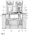
- the Fig. 4 shows a door frame 2 according to the invention on a sliding door and arranged in the bottom area spacers with height adjustment.
- the embodiment according to the Fig. 4 is substantially similar to the previous illustration of Fig. 3 or also the Fig. 2 , It differs in that 2/1 widening profiles 9/1, 9/2 are arranged below the lower frame part, which have a height adjustment 9/3 or 9/4. All other reference numerals have already been presented and are also available in Fig. 4 used in the same way, so that is renounced to a new idea.
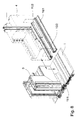
- the Fig. 5 shows an exploded view of another embodiment of the door frame 2 according to the invention.
- the reference numeral 1 the threshold, here shown as essay threshold referred to. With 1/2 is again the thermal break and designated 1/3 the carriage rail.
- Part of the door frame 2 is in the Fig. 5 shown on the top right.
- An arrow indicates that a compensation profile 100 can be connected there.
- Below the compensation profile 100 is shown an end cap, which is glued to the end of the compensation profile, for example with PVC adhesive.
- a holding plate 110 is shown, which (not shown) can be fastened with a particular angled composite sheet 110/1 for connecting an on-site geomembrane.
- This holding plate 110 can either be attached laterally to the ground sill 1 or else to the lower frame part 2/1.
- the latter embodiment is included Not shown.
- Below the lower frame part 2/1 are widenings 8/1 and 8/2.
- the second connecting means 8/3 are shown, by means of which the widenings 8/1 and 8/2 can be fastened to the lower frame part 2/1.
- Still further below are widening profiles 9/1 and 9/2, which likewise have second connecting means 9/5, by means of which the widening profile 9/1 or 9/2 either at the widening 8/1 or 8/2 or at the lower frame part 2/1 is attachable.
- the spacers no matter whether 8 or 9, directly to the ground sill 1, if there the first connection means are provided on the bottom.
- the reference numeral 12 is still a plastic profile for wall-side connection or wall-side sealing of the threshold shown. From this exploded view it is apparent how a door frame 2 according to the invention, in particular in the region of the lower frame part 2/1 composed.
- FIG. 6a and 6b Details of the attachment of the fixed wing 3 a sliding door or lifting / sliding door on the floor sill 1 of the door frame 2 according to the invention are shown.
- an adapter 6 is screwed with a fastening screw 13 under the fixed wing 3.
- the assembly of the adapter takes place before placing the fixed wing on the ground sill 1.
- the adapter also serves to leveling the slope, which has the bottom rail 1.
- For a vertical mounting position of the fixed wing 3 is secured.
- a part of the ground sill 1 is shown, this having a predetermined bending point 1/6, which has already been described earlier.
- the fixed wing 3 is placed on the ground sill 1 and as can be seen, the slope of the ground sill 1 is compensated by the adapter 6.
- the attachment is made from above with a further fastening screw 14th
- FIG. 7a and 7b Details of the fixed and the movable sash 3, 4 are shown with the bottom sill 1 of the door frame 2 according to the invention. It is essentially about the representation of the seal between the fixed wing 3 and movable wing 4. This is in the Fig. 7a the movable wing 4 shown in its lowered position. It can clearly be seen that the sealing pads 11/1 and 11/2 cooperate sealingly. The bottom seals 10/1 and 10/2 are seated on the ground sill 1 and slightly compressed. In the Fig. 7b the movable wing 4 is shown in its raised position. It is clear that the sealing elements are lifted from the threshold and the sealing elements of the fixed wing 3, so that a smooth movement of the movable wing can be done. The movable wing is guided by at least one roller 5 on the carriage rail 1/3.
- the Fig. 8 shows details of a lifting / sliding door with threshold 1 of the door frame 2 according to the invention in a three-dimensional view. It can be seen how the fixed wing 3 a lifting / sliding door is arranged on the bottom sill 1 and how the movable wing 4, z. B. is moved to close the door to the fixed wing 3 out.
- the reference numerals have been presented in total already, so that can be dispensed with a new idea.
- the presentation of the Fig. 8 serves essentially to show the mode of operation of a lifting / sliding door in cooperation with a door frame 2 (indicated here only as a floor sill 1).
- FIGS. 9 and 10 show a cover strip 1/4 and a carriage rail 1/3 for the door frame 2 according to the invention in a sectional view. It can be seen that the side edges were beveled by 30 °. This serves, as already described above, for receiving sealants and / or adhesives for producing an adhesive bond 15.
- the Fig. 11 shows in section an embodiment of the floor sill 1 as an attachment profile for the door frame 2 according to the invention. It can be seen that the recesses 1/1 and 1/5 are intended to receive a cover 1/4 or 1/3. A thermal separation is not provided in this variant, since this threshold can be obtained, for example, as a plastic profile, which is why no thermal separation is required. In an embodiment in light metal, z. As aluminum, of course, a thermal separation is provided, as previously described above.
- the threshold 1 can be performed according to the invention in wood, if desired!
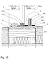
- the Fig. 12 and 13 show variants of a lifting / sliding door with a door frame 2 according to the invention, the illustration in the Fig. 12 a threshold 1, which has been obtained for example from plastic. Furthermore, the threshold 1 closes in the illustration according to Fig. 12 laterally with the edge of the lower frame profile 2/1 from. There, the prefabricated floor adjoins left and right in each case so that a barrier-free transition arises.
- Fig. 13 is a door frame with lower frame part 2/1 shown, which carries a threshold 1, for example made of aluminum profile.
- the threshold 1 made of aluminum has a thermal break 1/2 over which, for example, the carriage rail 1/3 is arranged. All other details have already been presented.
- the Fig. 14 shows a sliding door or lifting sliding door according to the invention in section, in this embodiment, a three-piece threshold 1 is connected to the lower frame part 2/1.
- the connection is made by means of clip connection, which are located between the lower frame part 2/1 and the middle part 1/10 of the bottom sill 1.
- the outwardly facing part 1/9 of the threshold is obtained in this embodiment of a metal profile, such as light metal and is, as can be seen, very well adapted to the finished floor.
- This embodiment allows in particular the favorable attachment of the seal.
- the predetermined bending point which may also be provided here, for example, at the junction between the lower frame part 2/1 and outer floor, is not shown in this embodiment.
- the middle part of the threshold carries the reference numeral 1/10 and can be made for example of plastic or fiber-reinforced plastic.
- a carriage rail 1/3 is placed in the bottom sill 1, wherein the carriage rail 1/3 carries or guides the movable sash 4.
- On the inward facing side of the third part of the three-part threshold, namely the inwardly facing part 1/8 of the threshold is arranged. This is located in a rail 1/12 and that in a provided there receiving groove 1/11.
- the fixed wing 3 shown on the left is fastened to the threshold with an adapter. The fastening means are not shown in this illustration.
- all the reference signs in the previous embodiments have already been presented, so that will not be discussed again.
- a seal is arranged here, this is usually referred to as Andichtung and here (also not shown) in a corresponding recess of the rail 1/12 or the inwardly facing part 1/8 of the threshold are attached.
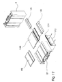
- the Fig. 15a, 15b . 16 and 17 show different views and Embodiments of a door frame in three-dimensional representation and partially designed as a so-called exploded view. It is quite clear here that the three-part threshold is arranged with the outwardly facing part 1/9, with the inwardly facing part 1/8 and with the middle part 1/10 on the lower frame part 2/1. It can be seen clearly that the vertically extending frame is notched in the region of the outwardly facing part 1/9 of the threshold to allow a dense and rich composite or a correspondingly dense resting on this part. This is shown in the illustration Fig. 16 even better visible.
- Fig. 15a the rail 1/12 is shown with the receiving groove 1/11, which receives the inward-facing part 1/8 of the frame.
- the rail 1/12 can be fastened in this embodiment by means of fastening screws on the lower frame part 2/1.
- the assembly process for the assembly of the individual frame parts and the parts of the bottom sill 1 can be seen.
- the four frame parts are usually cut to size.
- the portion of the frame or the frame extending vertically is unlatched on both sides, on which it rests on the outwardly facing part 1/9 of the threshold. This is indicated by a dashed line.
- a vertical positioning of the vertical frame member is made possible here and on the other hand a secure contact and possibly possible sealing achieved.
- the outward facing part 1/9 of the threshold is placed on the lower frame part and connected to this. Only then will be the other frame parts joined together to form an overall frame.
- the middle part 1/10 of the threshold are placed on the lower frame part and then either the, as in Fig. 16 shown integrally formed rail with the inwardly facing part of the threshold on the lower frame part 2/1 attached.
- one or more carriage rail (s) 1/3 in the middle part 1/10 of the threshold can be inserted.
- the order can be reversed chosen by first the carriage rail 1/3 is fitted and then the inwardly facing part 1/8 of the threshold is mounted.
- Fig. 17 is basically the same procedure as with Fig. 16 described, to choose.
- the rail 1/12 provided with a receiving groove 1/11, in which the inward-facing part 1/8 of the threshold can be inserted. It is done so that, for example, the rail 1/12 in the lower frame part 2/1 is then fastened when the outward-facing part 1/9 of the threshold is attached to this. Then the frame is assembled closed on four sides and then placed the middle part 1/10 of the threshold. Finally, the inward facing part 1/8 of the threshold and the carriage rail 1/3 is mounted as previously described.
Abstract
Description
Die Erfindung betrifft einen Türrahmen mit einer Bodenschwelle für eine Tür, die einen Außen- und einen Innenbereich beziehungsweise zwei Räume trennt.The invention relates to a door frame with a threshold for a door which separates an outer and an inner region or two spaces.
Derartige Türrahmen sind bekannt. Sie sind dadurch gekennzeichnet, daß der Türrahmen in der Regel als aus drei Rahmenteilen ausgebildeter Rahmen hergestellt wird und eine Bodenschwelle als unterer Rahmenteil und als Sonderprofil in diese Teilrahmen eingefügt wird. Dies hat den Nachteil, daß im Herstellungsprozeß die Verbindung des Teilrahmens, bestehend aus drei Rahmenelementen mit der Bodenschwelle mit mechanischen Mittel erfolgen muß. Dabei muß höchste Präzision gewahrt werden, da bereits leichte Verschiebungen sich später im eingebauten Zustand negativ auswirken, beziehungsweise dann, wenn die Tür eingebaut werden soll. Des weiteren müssen die mit der Montage betrauten Monteure darauf achten, daß sich der untere Rahmenteil, nämlich die Schwelle, während der Montage nicht verschiebt, so daß dadurch beispielsweise die Maßhaltigkeit nicht mehr gegeben ist. Es ist auch möglich, daß beim Montagevorgang die Bodenschwelle selbst deformiert wird, da sie möglicherweise nicht ausreichende Festigkeit aufweist, die erst durch den Verbund mit dem späteren Fertigfußboden (Estrich) hergestellt werden kann. Dadurch entstehen Unebenheiten, die sich negativ auf den bestimmungsgemäßen Einsatz auswirken.Such door frames are known. They are characterized in that the door frame is usually made as formed of three frame members frame and a threshold is inserted as a lower frame part and a special profile in this subframe. This has the disadvantage that in the manufacturing process, the connection of the subframe, consisting of three frame elements with the ground sill done by mechanical means got to. In this case, the highest precision must be maintained, since even slight displacements later in the installed state have a negative effect, or if the door is to be installed. Furthermore, the installers entrusted with the installation must ensure that the lower frame part, namely the threshold, does not shift during assembly, so that, for example, the dimensional stability is no longer given. It is also possible that during the assembly process, the threshold itself is deformed, since it may not have sufficient strength that can be produced only by the composite with the later finished floor (screed). This creates bumps that have a negative effect on the intended use.
Es ist auch bekannt, entsprechende Aufständerungen oder Verbreiterungen vorzusehen, um die Stabilität und den Einbau von Türrahmen zu erleichtern. Allerdings ist dies auch wieder mit zusätzlichen Aufwendungen verbunden, die das Problem der möglichen Deformation des Rahmens während des Montageprozesses aber immer noch nicht vollständig beheben. Für den Aufwand bei der Einfügung des Sonderprofils in Form der Bodenschwelle ergeben sich durch den Einsatz von Verbreiterungen keine zusätzlichen Einsparungseffekte.It is also known to provide appropriate elevations or extensions to facilitate the stability and installation of door frames. However, this is also associated with additional expenses that still do not completely solve the problem of possible deformation of the frame during the assembly process. For the effort in the insertion of the special profile in the form of the threshold resulting from the use of spacers no additional savings effects.
Ausgehend von dem zuvor beschriebenen Stand der Technik ist es Aufgabe der Erfindung, die Herstellung und die Montage von Türrahmen zu verbessern.Based on the above-described prior art, it is an object of the invention to improve the manufacture and assembly of door frames.
Die Aufgabe der Erfindung wird gelöst durch einen Türrahmen mit einer Bodenschwelle für eine Tür, die einen Außen- und einen Innenbereich beziehungsweise zwei Räume voneinander trennt, der sich dadurch auszeichnet, daß der Rahmen vierseitig geschlossen ausgebildet ist und der in Einbaustellung untere Rahmenteil die Bodenschwelle bildet. Mit "Bodenschwelle bildet" ist gemeint, daß der untere Rahmenteil sozusagen als Profil im Querschnitt der anderen drei Rahmenteile zwar entspricht, der untere Rahmenteil allerdings so ausgebildet ist, daß er gleichzeitig die Bodenschwelle bildet. Das heißt, daß der untere Rahmenteil entweder die Bodenschwelle selbst ist, oder aber die Schwelle dort angeformt oder aufgesetzt ist. Alle drei Ausgestaltungsmöglichkeiten sind von der Erfindung umfaßt. Durch diese erfindungsgemäße Ausbildung des Türrahmens, nämlich einen vierseitig geschlossenen Rahmen, der beispielsweise in Kunststoffbauweise vierseitig verschweißt wird und damit eine hohe Stabilität erhält, wurden die Nachteile des Standes der Technik vollständig beseitigt. Der untere Rahmenteil wird dann so bemessen, daß er im späteren Einbauzustand unterhalb beziehungsweise deckungsgleich mit dem Fertigfußboden ist, beispielsweise derart, daß die Bodenschwelle barrierefrei mit dem Fußboden eine Ebene bildet. Selbstverständlich kann auch eine Lösung mit der Erfindung realisiert werden, bei der nicht nur barrierefreie Übergänge realisiert werden. Es ist auch möglich, Türrahmen der vorher beschriebenen Art so in Gebäude einzusetzen, daß eine Schwelle entsteht. Von Vorteil ist es allerdings, wenn zumindest der untere Rahmenteil teilweise in dem späteren Fertigfußboden eingebaut ist, um einen entsprechenden Verbund zu sichern. Selbstverständlich ist es auch möglich, an den unteren Rahmenteil dann die üblichen Verbreiterungsprofile anzuschließen, um beispielsweise im Falle einer neuen Tür sozusagen die Neubauschwelle durch den unteren Rahmenteil zu bilden. Damit läßt sich der gesamte Türrahmen sehr günstig entsprechend des jeweiligen Fußbodenaufbaus, egal, ob nun eine Fußbodenheizung vorgesehen ist, oder nicht, entsprechend anpassen. Es ist selbstverständlich auch möglich, entsprechende Höhenverstelleinrichtungen an dem unteren Rahmenteil vorzusehen, mittels derer dann eine Feinjustierung des Türrahmens vor seiner Fixierung in den Gebäudewänden erfolgt.The object of the invention is achieved by a door frame with a threshold for a door which separates an outer and an inner region or two spaces from each other, which is characterized in that the frame is formed closed on four sides and the bottom frame in the installed position forms the bottom threshold , By "bottom sill forms" is meant that the lower frame part, so to speak as a profile in cross section Although the other three frame parts corresponds, but the lower frame part is designed so that it simultaneously forms the threshold. This means that the lower frame part is either the ground sill itself, or the threshold is formed or placed there. All three embodiments are encompassed by the invention. By this inventive design of the door frame, namely a four-sided closed frame, which is welded on four sides, for example in plastic construction and thus obtains a high stability, the disadvantages of the prior art have been completely eliminated. The lower frame member is then sized so that it is in the subsequent installed state below or congruent with the finished floor, for example, such that the threshold forms barrier-free with the floor a plane. Of course, a solution can be realized with the invention, in which not only barrier-free transitions are realized. It is also possible to use door frames of the type described above in buildings so that a threshold is created. It is advantageous, however, if at least the lower frame part is partially installed in the later finished floor to secure a corresponding composite. Of course, it is also possible to connect to the lower frame part then the usual widening profiles to form, for example in the case of a new door, so to speak, the new wave through the lower frame part. Thus, the entire door frame can be very low according to the respective floor structure, no matter whether a floor heating is provided or not, adjust accordingly. It is of course also possible to provide corresponding height adjustment devices on the lower frame part, by means of which then a fine adjustment of the door frame takes place before its fixation in the building walls.
Demnach zeichnet sich eine vorteilhafte Weiterbildung der Erfindung dadurch aus, daß der untere Rahmenteil die Bodenschwelle selbst ist, derart, daß die Bodenschwelle einstückig mit dem Rahmenteil ausgebildet und/oder am Rahmenteil angeformt ist. Einstückig bedeutet, daß der untere Rahmenteil sozusagen als Spezialprofil erhalten wurde, das in die Schweißmaschine beziehungsweise in die Montagelinie im Falle einer Leichtmetalltür mit einem entsprechenden Türrahmen eingelegt werden muß und dort entsprechend verbunden wird. Es ist allerdings auch möglich, daß ein normales Türrahmenprofil zunächst als Profil zur Verfügung gestellt wird und die Bodenschwelle dann dort angeformt wird. Dies kann beispielsweise durch Schweißen, Kleben, Verbinden mit Eckverbindern, Verschrauben oder dergleichen erfolgen.Accordingly, an advantageous development of the invention is characterized in that the lower frame part of the threshold itself is, such that the threshold is formed integrally with the frame part and / or formed on the frame part. One-piece means that the lower frame part was obtained, so to speak as a special profile, which must be inserted into the welding machine or in the assembly line in the case of a light metal door with a corresponding door frame and is connected there accordingly. However, it is also possible that a normal door frame profile is initially provided as a profile and the threshold is then formed there. This can be done for example by welding, gluing, joining with corner connectors, screwing or the like.
Demnach ist es nach der Erfindung ebenfalls vorgesehen, daß der untere Rahmenteil als Profil mit integrierter Bodenschwelle erhalten wurde. Dies bedeutet, daß für den unteren Rahmenteil ein Sonderprofil gezogen wird und beim bestimmungsgemäßen Zusammenbau des Türrahmens, egal ob in einer Schweißmaschine oder in einer Montagelinie, dann entsprechend geschweißt beziehungsweise montiert wird. Beim Kunststoffschweißen ist es günstig, daß der untere Rahmenteil sozusagen als Profil mit integrierter Bodenschwelle zur Verfügung gestellt wird, wodurch der Schweißvorgang des vierseitigen Rahmens auf einer Schweißmaschine realisiert werden kann. Der Türrahmen als solcher wird dadurch insgesamt sehr stabil. Er ist während der Montage kaum zu deformieren, da er entsprechende Stabilität durch den fest integrierten unteren Rahmenteil als Bodenschwelle erhält. Auch läßt sich die Montage, die ja beispielsweise im Neubau mit Orientierung an dem sogenannten Meterriß erfolgt, wesentlich günstiger gestalten und die Genauigkeit des Einbaus wird damit erhöht. Nacharbeiten sind dadurch fast vollständig ausgeschlossen.Accordingly, it is also provided according to the invention that the lower frame part was obtained as a profile with integrated threshold. This means that a special profile is drawn for the lower frame part and when properly assembled the door frame, whether in a welding machine or in an assembly line, then welded or assembled accordingly. In plastic welding, it is favorable that the lower frame part is provided so to speak as a profile with integrated threshold, whereby the welding process of the four-sided frame can be realized on a welding machine. The door frame as such is thus very stable overall. It is difficult to deform during assembly, as it receives appropriate stability through the integrated lower frame part as a threshold. Also, the installation, which takes place, for example, in the new building with orientation to the so-called meter crack, make much cheaper and the accuracy of installation is increased. Reworking is almost completely excluded.
Die Erfindung stellt allerdings auch eine Lösung zur Verfügung, bei der der Türrahmen aus vier normalen Profilen, zum Beispiel Aluminiumprofilen oder Aluminium-Verbundprofilen zusammengesetzt ist, wobei eben der untere Rahmenteil dann gleichzeitig den Teil der Bodenschwelle bildet, der in den Fußboden zumindest teilweise eingebaut wird und auf den dann ein Profil als Bodenschwelle, welches sehr dünn von der Materialstärke her gehalten ist, aufgesetzt wird. Das Aufsetzen kann dabei durch Anschrauben, Ankleben oder auch Aufschweißen vorgesehen sein. Damit ist es natürlich möglich, beispielsweise eine Kunststofftür mit entsprechendem Türrahmen mit einer Aluminium-Bodenschwelle auszustatten, die höheren Belastungen standhält als beispielsweise eine Kunststoffbodenschwelle. Selbstverständlich ist es auch möglich, eine Bodenschwelle aus Kunststoff auf dem unteren Rahmenteil aufzusetzen. Dies kann durch Kleben oder Schrauben, wie bereits erwähnt, erfolgen. Dabei kann die Bodenschwelle auch Dichtungselemente aufnehmen, wie dies beispielsweise bei magnetischen Türdichtungen bekannt ist.However, the invention also provides a solution in which the door frame is composed of four normal profiles, for example aluminum profiles or aluminum composite profiles is, where just the lower frame part then forms the same part of the threshold, which is at least partially installed in the floor and then placed on the profile as a threshold, which is very thin held by the material thickness, is placed. The placement can be provided by screwing, gluing or welding. Thus, it is of course possible, for example, to equip a plastic door with a corresponding door frame with an aluminum threshold, which withstands higher loads than, for example, a plastic floor sill. Of course, it is also possible to set up a plastic threshold on the lower frame part. This can be done by gluing or screwing, as already mentioned. The threshold can also absorb sealing elements, as is known for example in magnetic door seals.
Eine Weiterbildung der Erfindung zeichnet sich weiterhin dadurch aus, daß der Türrahmen für eine Tür mit einem sogenannten barrierefreien Übergang des durch die Tür getrennten Außen- und Innenbereichs beziehungsweise der getrennten Räume vorgesehen ist. Unter "barrierefrei" wird nach den derzeit geltenden Vorschriften auch noch eine Bodenschwelle verstanden, die eine Erhöhung gegenüber dem Fertigfußboden von 2 cm aufweist. Durch die Erfindung wird allerdings eine barrierefreie Lösung zur Verfügung gestellt, die es ermöglicht, die Bodenschwelle und den Fertigfußboden in einer Ebene anzuordnen, so daß überhaupt keine Übergänge oder aber nur 1 bis 2 mm Steigung aufgrund einer Wölbung des Profils zu überwinden sind. Gerade in Bereichen, in denen Behinderte mit Rollstuhl transportiert werden müssen, oder aber in Krankenhäusern, Pflegeheimen oder dergleichen, in denen Betten fahrbar von einem Raum zum anderen transportiert werden müssen, sind derartige barrierefreie Türen von besonderem Vorteil. Die Erfindung geht demnach über die geforderten Grenzen der Vorschriften hinaus und bietet eine Lösung an, die deutlich günstiger und damit komfortabler im späteren bestimmungsgemäßen Einsatz ist. Die Lösung ist dabei so, daß im Zusammenwirken mit dem oder den Türflügel(n) eine hervorragende Dichtigkeit, im Außenbereich sogar eine Schlagregendichtigkeit erreicht wird.A development of the invention is further characterized by the fact that the door frame is provided for a door with a so-called barrier-free transition of the separated by the door outer and inner areas or the separate rooms. According to the currently applicable regulations, "barrier-free" also means a threshold which has an increase of 2 cm compared to the finished floor. By the invention, however, a barrier-free solution is provided, which makes it possible to arrange the floor sill and the finished floor in a plane so that no transitions or only 1 to 2 mm slope due to a curvature of the profile are overcome. Especially in areas where people with disabilities need to be transported by wheelchair, or in hospitals, nursing homes or the like, in which beds must be transported from one room to another mobile, such barrier-free doors are of particular advantage. The invention thus goes beyond the required limits of the regulations and offers a solution that is much cheaper and thus more comfortable in the later intended use. The solution is such that in conjunction with the door or the wing (s) excellent tightness, in the outdoor area even a driving rain is achieved.
Eine vorteilhafte Variante der Erfindung zeichnet sich dadurch aus, dass der Türrahmen für eine Tür, eine Dreh-/Kipptür, ein Schiebeelement, ein Hebe-/Schiebeelement usw. vorgesehen ist. Der Türrahmen nach der Erfindung lässt sich dabei für jede Tür, egal ob eine Innentür oder Außentür, einsetzen. Besonders ist er allerdings natürlich für eine Außentür geeignet, die beispielsweise als Dreh-/Kipptür, als Schiebeelement oder Hebe-/Schiebeelemten ausgebildet sein kann. Dabei ist es möglich, den Türrahmen als Steckrahmen, der sozusagen in das Mauerwerk eingesteckt wird, vorgesehen ist. Es ist aber auch eine Ausführung als Blendrahmen oder als Zarge möglich. Die Erfindung ist hier nicht eingeschränkt. Sie lässt sich für alle Arten von Türrahmen einsetzen.An advantageous variant of the invention is characterized in that the door frame is provided for a door, a turn / tilt door, a sliding element, a lifting / sliding element, etc. The door frame according to the invention can be used for each door, whether an inner door or outer door. However, it is of course particularly suitable for an outer door, which can be designed, for example, as a revolving / tilting door, as a sliding element or lifting / Schiebeelemten. It is possible, the door frame as a plug-in frame, which is inserted as it were in the masonry, is provided. But it is also a version as a frame or as a frame possible. The invention is not limited here. It can be used for all types of door frames.
Der Türrahmen nach der Erfindung ist bezüglich des Materials nicht eingeschränkt. So ist es möglich, den Türrahmen aus Kunststoff, aus einem Kunststoff-Verbundwerkstoff, insbesondere faserverstärktem Kunststoff, wie zum Beispiel glasfaserverstärktem Kunststoff, Aluminium beziehungsweise Aluminium-Verbundwerkstoff oder aus Holz beziehungsweise Holz-Verbundwerkstoffen herzustellen.The door frame according to the invention is not limited in terms of the material. Thus, it is possible to produce the door frame made of plastic, a plastic composite material, in particular fiber-reinforced plastic, such as glass fiber reinforced plastic, aluminum or aluminum composite material or wood or wood composites.
Eine Weiterbildung der Erfindung zeichnet sich dadurch aus, dass für den Fall, dass die Bodenschwelle angeformt oder aufgesetzt wird, das Profil, insbesondere als Flachprofil mit einer Dicke von 1,5 mm bis 5 mm, bevorzugt 2,5 mm, ausgebildet ist. Damit lässt sich die Bodenschwelle als Profil einfacher und kostengünstiger herstellen, als dies bisher üblich war. Bei bisherigen Bodenschwellen musste man immer noch auf die Stabilität der Bodenschwelle entsprechend dem vorgenannten Problem im Stand der Technik achten, um eine Deformation beim Transport und insbesondere bei der Montage zu vermeiden. Jetzt ist es möglich, ein flaches Profil, egal ob aus Kunststoff oder Aluminium herzustellen und mit einer bevorzugten Materialstärke von maximal 2,5 mm auf dem unteren Rahmenteil als Bodenschwelle beziehungsweise als oberen Abschluss der Bodenschwelle aufzusetzen. Dies kann wie bereits vorher beschrieben im Herstellungsprozess des speziellen Profils für den unteren Rahmenteil erfolgen. Es ist allerdings auch möglich, eine solche Bodenschwelle als zusätzliches Profil für einen späteren Einbau, nämlich nach Montage des kompletten Rahmens, vorzusehen. Diese Bodenschwelle wird dann, nachdem der Rahmen komplett montiert ist und gegebenenfalls der Rohfußboden beziehungsweise Rohestrich aufgebracht ist, aufgebracht und der Fertigfußboden dann an die Bodenschwelle angepasst. Dabei kann dies so genau erfolgen, dass keinerlei Übergang vom Fertigfußboden, inklusive des Belags, zur Bodenschwelle her vorhanden ist, also sozusagen millimetergenau.A development of the invention is characterized in that, in the event that the threshold is formed or placed, the profile, in particular as a flat profile with a thickness of 1.5 mm to 5 mm, preferably 2.5 mm, is formed. This makes it possible to produce the threshold as a profile easier and cheaper than was usual. In previous bumps you still had to the stability of the threshold according to the above problem in the state of the art, to avoid deformation during transport and especially during assembly. Now it is possible to produce a flat profile, no matter whether made of plastic or aluminum, and with a preferred material thickness of a maximum of 2.5 mm on the lower frame part as a threshold or as the upper termination of the threshold. This can be done as already described in the manufacturing process of the special profile for the lower frame part. However, it is also possible to provide such a threshold as an additional profile for later installation, namely after assembly of the complete frame. This threshold is then after the frame is completely mounted and optionally the raw floor or rough screed is applied and then applied the finished floor to the threshold. This can be done so accurately that there is no transition from the finished floor, including the floor covering, to the threshold, so to speak with millimeter precision.
Die Bodenschwelle ist, wie bereits erwähnt, sowohl als Leichtmetallprofil, insbesondere Aluminiumprofil, als auch als Kunststoffprofil vorgesehen.The threshold is, as already mentioned, provided both as a light metal profile, in particular aluminum profile, as well as a plastic profile.
Ein Türrahmen nach der Erfindung zeichnet sich in einer Weiterbildung dadurch aus, dass die Bodenschwelle mehrteilig, insbesondere dreiteilig ausgebildet ist, wobei zumindest ein in Einbaustellung nach außen gerichteter Teil und ein weiterer, auf der Innenseite vorgesehener Teil der Bodenschwelle aus Metall, vorzugsweise aus Leichtmetall gebildet ist. Die dreiteilige Ausgestaltung der Bodenschwelle erleichtert das Verbinden des Türrahmens beziehungsweise das anschließende Aufsetzen der Flachschwelle. Des Weiteren ermöglicht diese Variante der Erfindung eine Ausbildung mit unterschiedlichen Materialkomponenten. So ist es beispielsweise sinnvoll, die äußere und innere Seite einer solchen Bodenschwelle aus Metall, vorzugsweise Leichtmetall, wie zum Beispiel Aluminium oder Aluminium-Verbundwerkstoff herzustellen und den mittleren Teil, der nicht solchen Starken Belastungen ausgesetzt ist wie die äußeren beziehungsweise inneren Teile, aus Kunststoff oder Kunststoff-Verbundmaterial.A door frame according to the invention is characterized in a further development in that the threshold is formed in several parts, in particular three parts, wherein at least one in the installed position outwardly directed part and another, provided on the inside of the part of the threshold of metal, preferably made of light metal is. The three-part design of the threshold makes it easier to connect the door frame or the subsequent placement of the flat sill. Furthermore, this variant of the invention allows training with different material components. So it makes sense, for example, the outer and inner side of such a threshold of metal, preferably Alloy metal, such as aluminum or aluminum composite material and the middle part, which is not exposed to such strong loads as the outer or inner parts, made of plastic or plastic composite material.
Die Laufwagenschiene einer Schiebetüre kann dabei beispielsweise wieder in eine Nut der Flachschwelle eingelassen werden, wobei die Laufwagenschiene selbstverständlich vorzugsweise ebenfalls aus einem metallischen Material gebildet ist. Die Montage läßt sich dabei derart vereinfachen, dass zum Beispiel zunächst der untere Teil der Zarge beziehungsweise des Türrahmens mit dem äußeren Teil der Bodenschwelle verbunden wird. Dann wird der Rahmen vierseitig geschlossen, wie üblich, und anschließend werden der mittlere Teil der Bodenschwelle aufgesetzt und anschließend der innere Teil der Bodenschwelle, beispielsweise mittels eines Winkelprofils an dem unteren Rahmenteil befestigt, derart, dass alle Teile der Bodenschwelle in einer Ebene liegen.The carriage rail of a sliding door can, for example, be recessed into a groove of the flat sleeper, wherein the carriage rail is of course also preferably formed from a metallic material. The assembly can be simplified in such a way that, for example, first the lower part of the frame or the door frame is connected to the outer part of the threshold. Then the frame is closed on four sides, as usual, and then the middle part of the threshold are placed and then the inner part of the threshold, for example by means of an angle profile attached to the lower frame part, such that all parts of the threshold lie in one plane.
Dazu ist es selbstverständlich vorgesehen, dass entweder entsprechende Verbindungsmittel an den einzelnen Teilen der Bodenschwelle vorgesehen sind, als auch eine entsprechende Ausnehmung, in die beispielsweise ein Teil eingreifen kann, wie das bevorzugt auf der Innenseite der Bodenschwelle gemäß einer Variante der Erfindung ausgeführt ist. Der weitere Vorteil einer solchen Ausgestaltung ist darin zu sehen, dass die nach außen und innen weisenden Teile der Bodenschwelle mit einer Sollbiegestelle versehen werden, um die Bodenschwelle nach ihrem Einbau und der Herstellung des Fertigfußbodens beziehungsweise des Bodenbelages, dann auf diesen aufzudrücken, so dass dort eine absatzlose Verbindung entsteht.For this purpose, it is of course provided that either corresponding connection means are provided on the individual parts of the threshold, as well as a corresponding recess in which, for example, a part can engage, as is preferably carried out on the inside of the threshold according to a variant of the invention. The further advantage of such a configuration is the fact that the outwardly and inwardly facing parts of the threshold are provided with a predetermined bending point to the threshold after their installation and the production of the finished floor or floor covering, then aufzudrücken on this, so that there a lossless connection arises.
Bei der Herstellung von Fertigfußböden besteht häufig das Problem, dass man nicht millimetergenau die Bodenschwelle beziehungsweise das Höhenniveau der Bodenschwelle trifft, weshalb eine solche Abbiegesollstelle sich äußerst günstig auf den späteren bestimmungsgemäßen Einsatz auswirkt. Selbstverständlich kann man anschließend dort auch noch eine entsprechende Versiegelungsnaht beziehungsweise eine Silikonnaht vorsehen, um die Bodenschwelle komplett abzudichten.In the production of prefabricated floors, there is often the problem that you do not millimeter exactly the threshold or the height level of the threshold meets, which is why such a turn-off point is extremely beneficial to the subsequent intended use. Of course, you can then there also provide a corresponding sealing seam or a silicone seam to completely seal the threshold.
Eine Weiterbildung der Erfindung zeichnet sich demnach dadurch aus, dass zumindest der nach außen gerichtete Teil der Bodenschwelle mit dem mittleren Teil verbindbar, insbesondere Zusammensteckbar oder auf- beziehungsweise einclipsbar ist. Solche Verbindungsmittel sind im Stand der Technik herkömmlich bekannt und dienen der lösbar festen Verbindung von solchen Bauelementen. Gerade bei Bodenschwellen beziehungsweise dem Anschluss von Verbreiterungsprofilen an Türrahmen oder Zargenprofilen ist diese Verbindungstechnik geläufig. Sie wird auch hier vorteilhafterweise gemäß einer Ausgestaltung der Erfindung eingesetzt.A development of the invention is therefore characterized in that at least the outwardly directed part of the threshold is connectable to the middle part, in particular zusammensteckbar or up or einclipsbar. Such connection means are conventionally known in the art and serve the releasably strong connection of such components. Especially with thresholds or the connection of widening profiles on door frames or Zargenprofilen this connection technology is common. It is also advantageously used here according to an embodiment of the invention.
Ein weiterer Aspekt des erfindungsgemäßen Türrahmens ist dadurch angegeben, dass der auf der Innenseite der Bodenschwelle vorgesehene Teil mittels einer eine Aufnahmenut aufweisenden Schiene an dem unteren Rahmenteil und/oder an dem mittleren Teil der Bodenschwelle befestigbar, insbesondere mit Befestigungsmitteln befestigbar ist. Als Befestigungsmittel sind auch hier wieder die bereits genannten Befestigungsmittel wie Clipsen oder Klemmen genannt. Selbstverständlich ist auch eine Schraubverbindung durchaus erfindungsgemäß mit umfasst. Eine einstückige Ausgestaltung des inneren Teils der Bodenschwelle mit der Schiene ist ebenfalls Gegenstand der Erfindung.A further aspect of the door frame according to the invention is specified in that the part provided on the inside of the threshold can be fastened to the lower frame part and / or to the middle part of the threshold by means of a rail having a receiving groove, in particular fastened with fastening means. As fastening means, the already mentioned fastening means such as clips or clamps are again mentioned here. Of course, a screw is quite according to the invention includes. A one-piece design of the inner part of the threshold with the rail is also an object of the invention.
Von Vorteil ist es dabei weiterhin, wenn die Bodenschwelle in Einbaurichtung auf ihrer Unterseite der Oberfläche des Blendrahmenprofils angepasst ist beziehungsweise entspricht, insbesondere derart, dass die Bodenschwelle formschlüssig auf dem unteren Rahmenteil aufsetzbar beziehungsweise dort befestigbar ist. Dies ist eine besonders günstige Variante und erspart auch viel Zeit bei der Montage dieser Bodenschwelle. Für den bestimmungsgemäßen Einsatz muss ein vierseitig fertiggestellter, z. B. geschweißter Türrahmen entsprechend der später gewünschten Höhe positioniert werden und die Bodenschwelle wird dann, wenn sie entsprechend formschlüssig zu dem unteren Rahmenteil passt, auf diesen nur aufgesetzt und dort entweder aufgeklebt oder aufgeschraubt. Das Aufschrauben kann dabei selbstverständlich verdeckt erfolgen, sodass auch durch die Verschraubung keine Hindernisse für den späteren barrierefreien Übergang, wie eingangs definiert, entstehen.It is advantageous, furthermore, if the threshold is adapted in the direction of installation on its underside of the surface of the frame profile or corresponds, in particular such that the threshold on the form-fitting lower frame part can be placed or fastened there. This is a particularly favorable variant and also saves a lot of time when mounting this threshold. For the intended use, a four-sided finished, z. B. welded door frame can be positioned according to the later desired height and the threshold is then, if it fits correspondingly positively to the lower frame part, placed on this only and either glued or screwed there. The screwing can of course be done concealed, so that no obstacles for the later barrier-free transition, as defined above, arise through the screw.
Die Bodenschwelle nach der Erfindung ist auch dadurch gekennzeichnet, dass eine thermische Trennung vorgesehen ist, die insbesondere durch einen Teil des Profils der Bodenschwelle selbst angegeben ist, wobei bevorzugt die Profilteile Verbindungselemente zur Verbindung untereinander aufweisen. Das heißt, dass die Bodenschwelle vorteilhafterweise mehrteilig ausgebildet ist, z. B. aus ein oder zwei Aluminiumteilen, die durch ein Kunststoffteil getrennt sind. Durch eine solche Ausgestaltung ist es möglich, die thermische Trennung zu erhalten und den Wärmedurchgang durch ein Aluminiumprofil beispielsweise zu unterbrechen. Die Kunststoffteile der Bodenschwelle können dabei so geschickt ausgestaltet sein, dass sie mit entsprechenden Aluminiumabdeckungen wieder geschlossen beziehungsweise abgedeckt werden, sodass rein äußerlich nur wenig vom Materialunterschied erkennbar ist.The threshold according to the invention is also characterized in that a thermal separation is provided, which is indicated in particular by a part of the profile of the threshold itself, preferably the profile parts have connecting elements for connection with each other. This means that the threshold is advantageously designed in several parts, z. Example of one or two aluminum parts, which are separated by a plastic part. By such a configuration, it is possible to obtain the thermal separation and to interrupt the heat transfer through an aluminum profile, for example. The plastic parts of the threshold can be designed so clever that they are closed or covered again with appropriate aluminum covers, so that only a little bit of the difference in material can be seen on the outside.
Demnach ist der Türrahmen entsprechend einer vorteilhaften Variante der Erfindung dadurch gekennzeichnet, dass in der Bodenschwelle wenigstens eine, bevorzugt zwei Vertiefungen vorgesehen sind, die zum einen der verdeckten Befestigung der Bodenschwelle auf dem unteren Rahmenteil dienen oder aber der Aufnahme beispielsweise einer Laufwagenschiene für eine Schiebetür oder einer Abdeckung oder dergleichen dienen. Wenn nun diese Vertiefungen beispielsweise aus einem Kunststoffprofilteil erhalten wurden, dann ist es möglich, diese gleichzeitig als thermische Trennung auszubilden. Zumindest eine der Vertiefungen, wie vorher beschrieben, bildet demnach vorteilhafterweise die thermische Trennung.Accordingly, the door frame according to an advantageous embodiment of the invention is characterized in that in the threshold at least one, preferably two recesses are provided, which serve for a hidden mounting of the threshold on the lower frame part or the recording example of a carriage rail for a sliding door or a cover or the like. Now, if these recesses were obtained for example from a plastic profile part, then it is possible to form them simultaneously as a thermal separation. Accordingly, at least one of the recesses, as described above, advantageously forms the thermal separation.
Die Erfindung schlägt auch vor, dass der Türrahmen sich gemäß einer Weiterbildung dadurch auszeichnet, dass die Abdeckung und/oder die Laufwagenschiene für die Bodenschwelle selbst als Profile beziehungsweise Profilteile, insbesondere als Leiste ausgebildet sind.The invention also proposes that the door frame is characterized according to a development characterized in that the cover and / or the carriage rail for the threshold are themselves formed as profiles or profile parts, in particular as a bar.
Diese Laufwagenschiene beziehungsweise Abdeckung sind im Querschnitt gesehen seitlich abgeschrägt beziehungsweise angefast, vorteilhafterweise nach innen abgewinkelt, sodass der entstehende Spalt an der Oberfläche der Bodenschiene später nicht sichtbar ist, allerdings nach innen zu eine Öffnung entsteht, die dreieckförmig ausgebildet ist. In diese Öffnung kann beispielsweise ein Kleber eingebracht werden, um die Abdeckung beziehungsweise die Laufwagenschiene zu befestigen. Vorteilhafterweise besitzt die Abdeckung beziehungsweise die Laufwagenschiene eine Abschrägung mit einem auf die Außenkante bezogenen Winkel von 20° bis 40°, bevorzugt von 30°.This carriage rail or cover are seen in cross section laterally chamfered or chamfered, advantageously angled inward, so that the resulting gap on the surface of the bottom rail is not visible later, but inwardly to an opening is formed, which is triangular. In this opening, for example, an adhesive can be introduced to secure the cover or the carriage rail. Advantageously, the cover or the carriage rail has a bevel with an angle to the outer edge of 20 ° to 40 °, preferably of 30 °.
Ein Türrahmen nach der Erfindung zeichnet sich entsprechend einer Variante der Erfindung dadurch aus, dass die Bodenschwelle und/oder der untere Rahmenteil in Einbaurichtung auf ihrer Unterseite erste Verbindungsmittel, insbesondere angeformte Verbindungsmittel aufweisen, die mit an Verbreiterungsprofilen und/oder an einem an der Bodenschwelle oder an dem unteren Rahmenteil anschließbaren Adapter vorgesehenen korrespondierend ausgebildeten zweiten Verbindungsmitteln verbindbar sind. Damit hat man alle Optionen offen, an dem unteren Rahmenteil oder aber an der Bodenschwelle selbst einen Adapter anzuschließen und an dem Adapter entsprechend ausgebildete Verbreiterungsprofile unterschiedlichster Art, da der Adapter für unterschiedliche Verbreiterungsprofile ausgebildet sein kann. Er kann selbstverständlich auch an entsprechende Verbreiterungsprofile unterschiedlicher Hersteller jeweils angepasst werden beziehungsweise für diesen Zweck vorgehalten werden. Das gleiche ist der Fall, wenn an dem unteren Rahmenteil Verbreiterungen angeschlossen werden sollen. Diese können beispielsweise vom gleichen System zur Verfügung gestellt werden, sodass eine Verbindung problemlos erfolgen kann. Es ist aber auch möglich, Verbreiterungsprofile anderer Systemgeber zu verwenden, weshalb dann ein Adapter dazwischengeschaltet werden sollte.A door frame according to the invention is characterized according to a variant of the invention in that the bottom threshold and / or the lower frame part in the installation direction on its underside first connecting means, in particular integrally formed connecting means, with at widening profiles and / or at the bottom threshold or connectable to the lower frame part adapter provided correspondingly formed second connection means are connectable. This one has all options open on the lower frame part or on the threshold itself an adapter connect and trained on the adapter extension profiles of various kinds, since the adapter can be designed for different extension profiles. Of course, it can also be adapted to respective widening profiles of different manufacturers or kept for this purpose. The same is the case if extensions are to be connected to the lower frame part. These can be provided by the same system, for example, so that a connection can be made easily. But it is also possible to use widening profiles of other system encoders, which is why an adapter should be interposed.
Demnach ist an dem Türrahmen nach der Erfindung an dem unteren Rahmenteil beziehungsweise an die Bodenschwelle in Einbaurichtung nach unten weisend wenigstens ein Verbreiterungsprofil und/oder ein Adapter anschließbar, insbesondere anclipsbar. Clipsverbindungen eignen sich in hervorragender Weise, um beispielsweise Aluminium- oder Kunststoffprofile untereinander zu verbinden.Accordingly, at least one widening profile and / or an adapter can be connected, in particular clipped, to the door frame according to the invention on the lower frame part or on the floor sill in the installation direction pointing downwards. Clip connections are excellently suited, for example, to connect aluminum or plastic profiles with each other.
Nach der Erfindung ist es weiterhin auch möglich, einen Adapter zwischen Bodenschwelle und unterem Rahmenteil anzuordnen, um diese miteinander zu verbinden.According to the invention, it is also possible to arrange an adapter between the bottom sill and the lower frame part in order to connect them together.
Von Vorteil ist es auch, wenn die Bodenschwelle des erfindungsgemäßen Türrahmens im Schnitt gesehen an wenigstens einer, bevorzugt an beiden Seiten, beabstandet vom Rand, eine Sollbiegestelle aufweist, um das Ende der Bodenschwelle nach dem Einbau auf den Fertigfußboden zu drücken beziehungsweise die Bodenschwelle an den Fertigfußboden anzugleichen. Mit dieser Ausführungsform gelingt es, gegebenenfalls noch vorhandene leichte Unterschiede, die im Millimeterbereich liegen, auszugleichen. Selbstverständlich kann man vor dem Herunterbiegen einen Klebstoff oder eine Silikonfuge beispielsweise noch Unterlegen, um eine dauerhaft feste und dichte Verbindung mit dem Fertigfußboden herzustellen.It is also advantageous if the threshold of the door frame according to the invention seen in section on at least one, preferably on both sides, spaced from the edge, a predetermined bending point to press the end of the threshold after installation on the finished floor or the ground sill to the Align finished floor. With this embodiment, it is possible, if necessary, to compensate for any slight differences which are in the millimeter range. Of course you can before bending down For example, an adhesive or a silicone joint still inferior to produce a permanently strong and tight connection with the finished floor.
Selbstverständlich ist es nach der Erfindung auch möglich, an dem vorher beschriebenen Adapter und/oder dem Verbreiterungsprofil weitere Verbreiterungen und/oder Profile beziehungsweise Profilteile anzuschließen.Of course, it is also possible according to the invention to connect to the previously described adapter and / or the widening profile wider spacers and / or profiles or profile parts.
Von Vorteil ist es weiter, wenn an dem unteren Rahmenteil und/oder der am nächsten in Bodennähe angeordneten Verbreiterung wenigstens eine Höhenverstelleinrichtung angeordnet beziehungsweise dort anordenbar ist. Mit dieser Höhenverstelleinrichtung lässt sich dann ein gegebenenfalls noch vorhandener Zwischenraum zwischen dem Rohfußboden und dem unteren Rahmenteil beziehungsweise der untersten Verbreiterung überbrücken und insbesondere lässt sich dadurch erreichen, dass man den Türrahmen millimetergenau mit der Höhenverstelleinrichtung einjustiert, bevor dieser dann beispielsweise seitlich fixiert und eingeschäumt beziehungsweise eingeputzt wird.It is furthermore advantageous if at least one height adjustment device is arranged or can be arranged there on the lower frame part and / or the widening arranged closest to the bottom. With this height adjustment can then be bridged an optionally existing gap between the unfinished floor and the lower frame part or the lowest broadening and in particular can be achieved by adjusting the door frame with millimeter precision with the height adjustment, before then then for example laterally fixed and foamed or plastered becomes.
Die Erfindung zeichnet sich gemäß einer Variante dadurch aus, dass die Verbreiterung zumindest teilweise wärmegedämmt ist. Damit gelingt es, beispielsweise vorhandene Probleme im Bereich unterhalb der Bodenschwelle des Türrahmens zu lösen, indem dort eine ausreichende Wärmedämmung zur Verfügung gestellt wird. Die auf den Baustellen noch häufig verbreitete "Handwerkelei", indem dort bestimmte Dämmmaterialien untergestellt werden, und diese möglicherweise beim Einbringen des Estrichs verrutschen, gehören damit der Vergangenheit an.The invention is characterized according to a variant in that the broadening is at least partially thermally insulated. This makes it possible, for example, to solve existing problems in the area below the threshold of the door frame by providing sufficient heat insulation there. The "craftsmanship" still common on construction sites, where certain insulation materials are placed under them, and these may slip when the screed is introduced, is now a thing of the past.
Der erfindungsgemäße Türrahmen lässt sich demnach millimetergenau auf den späteren Fertigfußboden einjustieren, das heißt, das untere Rahmenteil wird in Einbaustellung mit seiner Oberkante auf dem Höhenniveau des Fertigfußbodens beziehungsweise um das Maß der Materialstärke der Bodenschwelle unterhalb des Höhenniveaus vom Fertigfußboden angeordnet, derart, dass die Bodenschwelle im eingebauten Zustand barrierefrei an den Fertigfußboden anschließt. Im Falle einer einstückigen Bodenschwelle mit unterem Rahmenteil wird natürlich die Oberfläche der Bodenschwelle des unteren Rahmenteils so einjustiert, dass sie millimetergenau an den Fertigfußboden anschließt.The door frame according to the invention can therefore be adjusted to the millimeter precision on the later finished floor, that is, the lower frame part is in the installed position with its upper edge at the height level of the finished floor or arranged by the degree of material thickness of the threshold below the height level of the finished floor, so that the threshold in the installed state connects barrier-free to the finished floor. In the case of a one-piece floor sill with lower frame part, of course, the surface of the bottom sill of the lower frame part is adjusted so that it connects with millimeter precision to the finished floor.
Der erfindungsgemäße Türrahmen zeichnet sich in einer weiterbildung auch dadurch aus, dass an der Bodenschwelle eine Halteplatte mit einem insbesondere abgewinkelten Verbundblech zum Anschluß einer bauseitigen Dichtungsbahn befestigbar ist. Hierbei handelt es sich um eine sehr effektive und sinnvolle Ergänzung des erfindungsgemäßen Türrahmens, die gewährleistet, dass gegebenenfalls anbringbare Dichtungsbahnen sehr leicht an der Bodenschwelle beziehungsweise auch im Bereich neben der Bodenschwelle und im Bereich neben den Rahmenteilen angeordnet werden kann.The door frame according to the invention is characterized in a further development also by the fact that at the threshold a retaining plate with a particular angled composite sheet for connection to an on-site geomembrane can be fastened. This is a very effective and useful supplement to the door frame according to the invention, which ensures that optionally attachable geomembranes can be very easily arranged on the threshold or in the area next to the threshold and in the area next to the frame parts.
Die Erfindung stellt auch eine Tür mit wenigstens einem Flügel und einem Türrahmen, wie vorher beschrieben, zur Verfügung. Des Weiteren wird durch die Erfindungs insbesondere eine Hebe-/Schiebetür mit wenigstens einem bewegbaren beziehungsweise schiebbaren Flügel und einem Türrahmen, wie vorher beschrieben, zur Verfügung gestellt.The invention also provides a door having at least one wing and a door frame as previously described. Furthermore, the invention provides in particular a lifting / sliding door with at least one movable or sliding wing and a door frame, as described above.
Entsprechend einer vorteilhaften Weiterbildung zeichnet sich die Hebe-/Schiebetür dadurch aus, dass wenigstens ein fester Flügel vorgesehen ist, der mittels eines Adapters auf der Bodenschwelle angeordnet ist.According to an advantageous development, the lifting / sliding door is characterized in that at least one fixed wing is provided, which is arranged by means of an adapter on the ground sill.
Die Erfindung schlägt auch eine Hebe-/Schiebetür, wie vorher beschrieben vor, die sich dadurch auszeichnet, dass an dem festen Flügel auf der zum beweglichen Flügel weisenden Seite in Einbaurichtung auf der Bodenschwelle ein erstes Dichtkissen vorgesehen ist. Es ist weiterhin vorgesehen, dass an der Hebe-/Schiebetür, wie vorher beschrieben, am beweglichen Flügel in Einbaurichtung auf der Unterseite zum festen Flügel weisend, ein zweites Dichtkissen angeordnet ist, das im geschlossenen Zustand der Tür mit dem ersten Dichtkissen dichtend zusammenwirkt.The invention also proposes a lifting / sliding door, as described above, which is characterized in that on the fixed wing on the side facing the movable wing in the direction of installation on the ground sill a first sealing pad is provided. It is further provided that on the lifting / sliding door, as described above, facing the movable wing in the direction of installation on the bottom to the fixed wing, a second sealing cushion is arranged, which cooperates sealingly in the closed state of the door with the first sealing cushion.
Die Erfindung schlägt weiterhin eine Hebe-/Schiebetür vor, die sich dadurch auszeichnet, dass auf der Unterseite des beweglichen Flügels beziehungsweise zur Bodenschiene weisend wenigstens eine, bevorzugt zwei Bodendichtungen angeordnet sind. Diese dienen der Abdichtung des Zwischenraumes zwischen dem Flügel und der Bodenschwelle im geschlossenen Zustand der Tür.The invention further proposes a lifting / sliding door, which is characterized in that at least one, preferably two bottom seals are arranged pointing to the underside of the movable wing or to the bottom rail. These serve to seal the gap between the wing and the threshold in the closed state of the door.
Die Erfindung zeichnet sich des Weiteren dadurch aus, dass die Hebe-/Schiebetür, wie vorher beschrieben, einen beweglichen Flügel aufweist und der bewegliche Flügel einen Laufwagen mit wenigstens einer Laufrolle besitzt, die auf der Laufwagenschiene der Bodenschwelle aufliegt beziehungsweise von dieser geführt ist.The invention is further characterized in that the lifting / sliding door, as described above, has a movable wing and the movable wing has a carriage with at least one roller, which rests on the carriage rail of the threshold or is guided by this.
Die Erfindung zeichnet sich weiterhin dadurch aus, dass die Laufwagenschiene und/oder die Abdeckung für die Bodenschwelle mittels einer Klebeverbindung auf der Bodenschiene befestigt ist (sind).The invention is further characterized in that the carriage rail and / or the cover for the threshold is (are) attached by means of an adhesive bond on the bottom rail.
Die Tür nach der Erfindung, wie vorher beschrieben, zeichnet sich dadurch aus, daß sie als Kunststoff oder Kunststoff-Verbundtür, als Aluminium oder Aluminium-Verbundtür, als Holztür beziehungsweise Tür aus einem Holz-Verbundwerkstoff ausgebildet ist.The door according to the invention, as described above, is characterized in that it is designed as a plastic or plastic composite door, as aluminum or aluminum composite door, as a wooden door or door made of a wood composite material.
Die Aufgabe der Erfindung wird auch gelöst durch ein Verfahren zur Herstellung eines Türrahmens, insbesondere eines Türrahmens wie vorher beschrieben, das gekennzeichnet ist durch folgende Verfahrensschritte:
- Zuschneiden aller vier Rahmenteile auf Maß
- Zusammenfügen der Rahmenteile durch mechanisches Verbinden der Rahmenteile und/oder Schweißen und/oder Kleben
- Aufsetzten der Bodenschwelle auf den unteren Rahmenteil und festes Verbinden mit diesem Rahmenteil durch Klemmen, Kleben, Schrauben, Clipsen oder Schweißen.
- Cutting all four frame parts to size
- Assembly of the frame parts by mechanically connecting the frame parts and / or welding and / or gluing
- Placing the threshold on the lower frame part and firmly connecting to this frame part by clamping, gluing, screwing, clipping or welding.
Ein solches Verfahren erzielt die bei der Beschreibung des erfindungsgemäßen Türrahmens bereits beschriebenen vorteilhaften Effekte ebenfalls. So ist es jetzt möglich, nach dem Zuschneiden aller Rahmenteile diese zusammenzufügen und zwar Werksseitig und diese Rahmenteile durch Schraubverbindungen, Press- oder Klemmverbindungen oder durch Schweißen oder Kleben miteinander zu verbinden. Anschließend wird die flache Bodenschwelle auf den unteren Rahmenteil aufgesetzt, wodurch gleichzeitig eine Bodenschwelle erhalten wird, die im bestimmungsgemäßen Einsatz satt aufliegt und die insbesondere durch die Verbindung mit dem unteren Rahmenteil eine hohe Stabilität besitzt, so dass beim Einbau der Tür beziehungsweise des Türrahmens sehr genau nach dem Fertigmaß des Fußbodens ausgerichtet werden kann und ein Verbiegen oder Verschieben durch das spätere Einbringen des Fertigfußbodens, der meist als Estrich eingebracht wird, nicht mehr vorkommen kann. Des Weiteren wird die Maßgenauigkeit deutlich erhöht. Des Weiteren wird auch die Wärmedämmung im Bereich der Bodenschwelle deutlich verbessert, da das Profil des unteren Teils des Rahmens aus dem gleichen Material erhalten wurde wie der gesamte Türrahmen, wodurch schon eine bessere Wärmedämmung gegeben ist als bei normalerweise einstückig ausgebildeten Aluminiumschwellen. Auch ist die Wärmedämmung insgesamt noch besser als bei beispielsweise Aluminiumbodenschwellen mit thermischer Trennung. Auch hier sind erfindungsgemäß durch das Verfahren zur HerstellungSuch a method also achieves the advantageous effects already described in the description of the door frame according to the invention. So it is now possible, after cutting all the frame parts together to assemble them and that factory and these frame parts by screw, press or clamp connections or by welding or gluing together. Subsequently, the flat threshold is placed on the lower frame part, whereby at the same time a threshold is obtained, which rests satisfactorily in the intended use and has a high stability, in particular by the connection with the lower frame part, so that when installing the door or the door frame very accurately can be aligned according to the finished size of the floor and a bending or moving through the subsequent introduction of the finished floor, which is usually introduced as screed, can no longer occur. Furthermore, the dimensional accuracy is significantly increased. Furthermore, the thermal insulation in the area of the threshold is significantly improved, since the profile of the lower part of the frame was obtained from the same material as the entire door frame, which is already better thermal insulation than in normally integrally formed aluminum sleepers. Also, the overall thermal insulation is even better than, for example, aluminum floor sleepers with thermal separation. Again, according to the invention by the process for the preparation
des Türrahmens sehr positive Effekte erhalten.the door frame received very positive effects.
Die Aufgabe der Erfindung wird auch gelöst durch ein weiteres Verfahren zur Herstellung eines Türrahmens, insbesondere eines Türrahmens wie vorher beschrieben, der sich insbesondere durch die Verwendung einer mehrteiligen, beispielsweise dreiteiligen Bodenschwelle auszeichnet. Dieses Verfahren zeichnet sich demnach durch folgende Verfahrensschritte aus:
- Zuschneiden aller vier Rahmenteile auf Maß,
- Aufsetzen beziehungsweise Aufclipsen des nach außen weisenden Rahmenteils auf den unteren Teil des Rahmens,
- Ausklinken des nach außen weisenden Teiles der seitlichen Rahmen- beziehungsweise Zargenprofile analog der Auflagefläche auf dem nach außen weisenden Rahmenteil;
- Aufsetzen beziehungsweise Befestigen, zum Beispiel Aufclipsen oder Kleben des mittleren Rahmenteils der Bodenschwelle auf dem unteren Rahmenteil,
- Verbinden der Schiene mit dem unteren Rahmenteil und/oder des mittleren Teils der Bodenschwelle,
- Befestigen des nach innen weisenden Teils der Bodenschwelle in beziehungsweise an der Schiene und/oder Bodenschwelle.
- Cutting all four frame parts to size,
- Placing or clipping the outwardly facing frame part onto the lower part of the frame,
- Notching the outwardly facing part of the lateral frame or Zargenprofile analogous to the support surface on the outwardly facing frame part;
- Attaching or fastening, for example clipping or gluing the middle frame part of the ground sill on the lower frame part,
- Connecting the rail to the lower frame part and / or the middle part of the threshold,
- Attaching the inwardly facing part of the threshold in or on the rail and / or threshold.
Auch durch dieses erfindungsgemäße Verfahren, welches insbesondere für die Ausgestaltung eines Türrahmens mit einer mehrteilig ausgebildeten Bodenschwelle vorgesehen ist, werden die zuvor beschriebenen Nutzeffekte in gleicher Weise erhalten. Man erhält hier allerdings noch den Vorteil, dass man unterschiedliche Materialien für die äußeren und inneren Teile beziehungsweise den mittleren Teil der Bodenschwelle verwenden kann, so dass beispielsweise einem höheren verschleiß ausgesetzt äußere und innere Teile aus Metall beziehungsweise Leichtmetall gefertigt werden können, während der mittlere Teil aus einem Kunststoff beziehungsweise Verbundkunststoff hergestellt ist. Die einem höheren Verschleiß ausgesetzte Laufwagenschiene, einer Schiebetüre oder Hebeschiebetüre, wird selbstverständlich ebenfalls aus Metall hergestellt und in einem weiteren Arbeitsschritt dann in den mittleren Teil der Bodenschwelle eingefügt.Also by this method according to the invention, which is provided in particular for the design of a door frame with a multiparty threshold, the above-described benefits are obtained in the same way. However, one still gets the advantage that you can use different materials for the outer and inner parts or the middle part of the threshold, so that, for example, a higher wear exposed outer and inner parts made of metal or light metal can be while the middle part is made of a plastic or composite plastic. Of course, the runner rail, a sliding door or lift-and-slide door, which is exposed to a higher level of wear, is likewise made of metal and then inserted into the middle part of the threshold in a further work step.
Der letzte Verfahrensschritt, wonach eine Befestigung des nach innen weisenden Teiles der Bodenschwelle in beziehungsweise an der Schiene und/oder Bodenschwelle vorgesehen ist, kann natürlich entfallen, wenn beispielsweise der nach innen weisende Teil der Bodenschwelle mit der Schiene einstückig ausgebildet ist. Dann wird diese Montage selbstverständlich in einem einzigen Arbeitsschritt erledigt.The last method step, according to which an attachment of the inwardly facing part of the threshold in or on the rail and / or threshold is provided, of course, can be omitted if, for example, the inwardly facing part of the threshold is integrally formed with the rail. Then, of course, this assembly is done in a single step.
Die Erfindung wird nachfolgend anhand von Ausführungsbeispielen weiter beschrieben.The invention will be further described by means of embodiments.
Es zeigen:
- Fig. 1a bis 1b
- eine erste Ausführungsform des erfindungsgemäßen Türrahmens;
- Fig. 2
- eine weitere Variante des Türrahmens nach der Erfindung im Schnitt mit im Bodenbereich ange-ordneten Verbreiterungsprofilen;
- Fig. 3a bis 3b
- vergrößerte Darstellung der Variante nach
Fig. 2 ohne Verbreiterungsprofil; - Fig. 4
- Türrahmen nach der Erfindung an einer Schiebetür und mit im Bodenbereich angeordneten Verbreiterungen mit Höhenverstelleinrichtungen;
- Fig. 5
- Explosionsdarstellung einer weiteren Ausführungsform des Türrahmens nach der Erfindung;
- Fig. 6a bis 6b
- Detail der Befestigung eines festen Flügels auf der Bodenschwelle des erfindungsgemäßen Türrahmens;
- Fig. 7a bis 7b
- Details von festem und beweglichem Flügel mit Bodenschwelle des erfindungsgemäßen Türrahmens;
- Fig. 8
- Detail einer Hebe-/Schiebetür mit Bodenschwelle des erfindungsgemäßen Türrahmens in dreidimensionaler Ansicht;
- Fig. 9 bis 10
- Abdeckleiste und Laufwagenschiene als Details für den erfindungsgemäßen Türrahmen in Schnittdarstellung;
- Fig. 11
- Ausführungsform der Bodenschwelle als Aufsatzprofil für den Türrahmen nach der Erfindung;
- Fig. 12
bis 13 - Ausführungsform eines Türrahmens nach der Erfindung in Holz;
- Fig. 14
- Ausführungsform der Erfindung als Schiebe- beziehungsweise Hebe- schiebetüre mit dreiteiliger Bodenschwelle nach der Erfindung und
- Fig. 15a, 15b, 16 und 17
- Verschiedene Darstellungen von Türrahmen mit dreiteiliger Bodenschwelle nach der Erfindung.
- Fig. 1a to 1b
- a first embodiment of the door frame according to the invention;
- Fig. 2
- a further variant of the door frame according to the invention in section with in the bottom region-arranged widening profiles;
- Fig. 3a to 3b
- enlarged view of the variant after
Fig. 2 without extension profile; - Fig. 4
- Door frame according to the invention on a sliding door and arranged in the bottom area widenings with height adjustment devices;
- Fig. 5
- Exploded view of another embodiment of the door frame according to the invention;
- Fig. 6a to 6b
- Detail of the attachment of a fixed wing on the threshold of the door frame according to the invention;
- Fig. 7a to 7b
- Details of fixed and movable wing with threshold of the door frame according to the invention;
- Fig. 8
- Detail of a lifting / sliding door with threshold of the door frame according to the invention in three-dimensional view;
- Fig. 9 to 10
- Cover strip and carriage rail as details for the door frame according to the invention in a sectional view;
- Fig. 11
- Embodiment of the threshold as an attachment profile for the door frame according to the invention;
- Fig. 12 to 13
- Embodiment of a door frame according to the invention in wood;
- Fig. 14
- Embodiment of the invention as a sliding or lifting Sliding door with three-piece threshold according to the invention and
- FIGS. 15a, 15b, 16 and 17
- Various representations of door frame with three-piece threshold according to the invention.
Die
Die in
Die
Die
Die
Auf der rechten Seite der Darstellung ist ein beweglicher Flügel 4 des Schiebeelementes gezeigt. Dieser ist mittels Laufrollen 5, die in einem nicht weiter gezeigten Laufwagen vorgesehen sind, geführt. Dazu ist die Laufwagenschiene 1/3 ebenfalls durch eine Kleberverbindung 15 an der Bodenschwelle 1 befestigt. Die Laufwagenschiene 1/3 führt die Laufrolle(n) 5 des beweglichen Flügels 4 des Schiebeelementes. Unterhalb des unteren Rahmenteiles 2/1 sind Verbreiterungsprofile 8/1 und 8/2 vorgesehen. Diese sind thermisch durch eine nicht bezeichnete Dämmung getrennt und mit Clipsverbindungen an dem unteren Rahmenteil 2/1 befestigt. Die Bodenschwelle 1 inclusive des unteren Rahmenteiles 2/1 ist so angeordnet, dass sie mit dem Fertigfussboden rechts und links neben dem Rahmen eine Ebene bildet. Damit entsteht ein völlig barrierefreier Übergang zwischen dem Außen- und dem Innenbereich beziehungsweise zwischen den zu trennenden Räumen, die durch die Schiebetür beziehungsweise das Schiebeelement getrennt werden. Der Vollständigkeit halber sind am festen und am beweglichen Flügel Dichtkissen 11/1 und 11/2 befestigt, die den unteren Randbereich im geschlossenen Zustand der Türe abdichten. Die Dichtkissen 11/1 und 11/2 sind dabei angeschrägt, so dass sie im geschlossenen Zustand der Türe aufeinanderliegen und so eine dichte Verbindung im Randbereich bilden. Unterhalb des beweglichen Flügels 4 des Schiebeelementes sind Bodendichtungen 10/1 und 10/2 jeweils außen und innen neben dem Laufrad 5 am beweglichen Flügel 4 angeordnet.On the right side of the illustration, a
Die
Die
Die
Die
In den
In den
Die
Die
Die
Die
In der
Die
Auch im inneren Bereich des Fußbodens ist hier eine Dichtung angeordnet, diese wird üblicherweise als Andichtung bezeichnet und kann auch hier (ebenfalls nicht dargestellt) in einer entsprechenden Ausnehmung der Schiene 1/12 beziehungsweise dem nach innen weisenden Teil 1/8 der Bodenschwelle befestigt werden.Also in the inner region of the floor a seal is arranged here, this is usually referred to as Andichtung and here (also not shown) in a corresponding recess of the
Die
Im Weiteren ist in
In den
Nachdem nun diese Ausklinkung vorgenommen wurde, wird der nach außen weisende Teil 1/9 der Bodenschwelle auf dem unteren Rahmenteil aufgesetzt und mit diesem verbunden. Erst dann werden die weiteren Rahmenteile zu einem Gesamtrahmen zusammengefügt. Dies hat den Vorteil, dass der nach außen weisende Teil 1/9 der Bodenschwelle sich über die gesamte Breite des Türrahmens beziehungsweise der Zarge erstreckt. Nachdem die vier Rahmenteile zusammengefügt sind, werden dann der mittlere Teil 1/10 der Bodenschwelle auf den unteren Rahmenteil aufgesetzt und anschließend entweder die, wie in
In
Die jetzt mit der Anmeldung und später eingereichten Ansprüche sind Versuche zur Formulierung ohne Präjudiz für die Erzielung weitergehenden Schutzes.The claims now filed with the application and later are attempts to formulate without prejudice to the attainment of further protection.
Sollte sich hier bei näherer Prüfung, insbesondere auch des einschlägigen Standes der Technik, ergeben, daß das eine oder andere Merkmal für das Ziel der Erfindung zwar günstig, nicht aber entscheidend wichtig ist, so wird selbstverständlich schon jetzt eine Formulierung angestrebt, die ein solches Merkmal, insbesondere im Hauptanspruch, nicht mehr aufweist.Should be here on closer examination, especially the pertinent prior art, that one or the other feature for the aim of the invention, although favorable, but not crucial, so it is of course already sought a formulation that no longer has such a feature, in particular in the main claim.
Es ist weiter zu beachten, daß die in den verschiedenen Ausführungsformen beschriebenen und in den Figuren gezeigten Ausgestaltungen und Varianten der Erfindung beliebig untereinander kombinierbar sind. Dabei sind einzelne oder mehrere Merkmale beliebig gegeneinander austauschbar. Diese Merkmalskombinationen sind ebenso mit offenbart.It should further be noted that the embodiments and variants of the invention described in the various embodiments and shown in the figures can be combined with one another as desired. Here, one or more features are arbitrarily interchangeable. These feature combinations are also disclosed with.
Die in den abhängigen Ansprüchen angeführten Rückbeziehungen weisen auf die weitere Ausbildung des Gegenstandes des Hauptanspruches durch die Merkmale des jeweiligen Unteranspruches hin. Jedoch sind diese nicht als ein Verzicht auf die Erzielung eines selbständigen, gegenständlichen Schutzes für die Merkmale der rückbezogenen Unteransprüche zu verstehen.The references cited in the dependent claims indicate the further development of the subject matter of the main claim by the features of the respective subclaim. However, these are not to be understood as a waiver of obtaining independent, objective protection for the features of the dependent claims.
Merkmale, die bislang nur in der Beschreibung offenbart wurden, können im Laufe des Verfahrens als von erfindungswesentlicher Bedeutung, zum Beispiel zur Abgrenzung vom Stand der Technik beansprucht werden.Features that have hitherto been disclosed only in the description may be claimed in the course of the method as of essential importance to the invention, for example to distinguish from the prior art.
Merkmale, die nur in der Beschreibung offenbart wurden, oder auch Einzelmerkmale aus Ansprüchen, die eine Mehrzahl von Merkmalen umfassen, können jederzeit zur Abgrenzung vom Stande der Technik in den ersten Anspruch übernommen werden, und zwar auch dann, wenn solche Merkmale im Zusammenhang mit anderen Merkmalen erwähnt wurden beziehungsweise im Zusammenhang mit anderen Merkmalen besonders günstige Ergebnisse erreichen.Features which have been disclosed only in the description, or also individual features of claims comprising a plurality of features, may at any time be included in the first claim for distinction from the prior art, even if such features are associated with others Characteristics were mentioned or achieve particularly favorable results in connection with other features.
Claims (21)
Applications Claiming Priority (1)
| Application Number | Priority Date | Filing Date | Title |
|---|---|---|---|
| DE200720015160 DE202007015160U1 (en) | 2007-10-30 | 2007-10-30 | Door frame with a threshold |
Publications (2)
| Publication Number | Publication Date |
|---|---|
| EP2055882A2 true EP2055882A2 (en) | 2009-05-06 |
| EP2055882A3 EP2055882A3 (en) | 2014-04-02 |
Family
ID=40282368
Family Applications (1)
| Application Number | Title | Priority Date | Filing Date |
|---|---|---|---|
| EP08016551.7A Withdrawn EP2055882A3 (en) | 2007-10-30 | 2008-09-19 | Door frame with a threshold |
Country Status (2)
| Country | Link |
|---|---|
| EP (1) | EP2055882A3 (en) |
| DE (1) | DE202007015160U1 (en) |
Cited By (3)
| Publication number | Priority date | Publication date | Assignee | Title |
|---|---|---|---|---|
| DE102014205287A1 (en) * | 2014-03-21 | 2015-09-24 | Roto Frank Ag | Sliding window or sliding door with a sealing element |
| CN107956372A (en) * | 2017-12-01 | 2018-04-24 | 江苏远翔装饰工程有限公司 | Accessible high-air-tightness outward swinging door |
| CN108049792A (en) * | 2017-12-01 | 2018-05-18 | 江苏远翔装饰工程有限公司 | The accessible combination door system of yarn push-and-pull is opened outdoors |
Families Citing this family (4)
| Publication number | Priority date | Publication date | Assignee | Title |
|---|---|---|---|---|
| AT510908B1 (en) | 2010-12-22 | 2015-10-15 | Ifn Holding Ag | BLEND FRAME |
| DE202016101390U1 (en) * | 2016-03-13 | 2016-04-29 | Veka Ag | Center seal block and center seal block system for a lift-and-slide door |
| CN109138739A (en) * | 2018-08-27 | 2019-01-04 | 中船澄西船舶修造有限公司 | A kind of peculiar to vessel detachable or hiding doorsill structure |
| DE102022206444B4 (en) | 2022-06-27 | 2024-03-07 | Profine Gmbh | Frame for a door with an extrusion frame and threshold, door with such a frame and method for producing this door |
Citations (3)
| Publication number | Priority date | Publication date | Assignee | Title |
|---|---|---|---|---|
| EP0877140A2 (en) * | 1997-05-07 | 1998-11-11 | Niemann, Hans Dieter | Doorframe |
| EP1582687A2 (en) * | 2004-03-30 | 2005-10-05 | Schüring GmbH & Co. Fenstertechnologie KG | Door sill system |
| WO2006040072A2 (en) * | 2004-10-09 | 2006-04-20 | Josef Westermann | Frame for a door, a window or the like |
-
2007
- 2007-10-30 DE DE200720015160 patent/DE202007015160U1/en not_active Expired - Lifetime
-
2008
- 2008-09-19 EP EP08016551.7A patent/EP2055882A3/en not_active Withdrawn
Patent Citations (3)
| Publication number | Priority date | Publication date | Assignee | Title |
|---|---|---|---|---|
| EP0877140A2 (en) * | 1997-05-07 | 1998-11-11 | Niemann, Hans Dieter | Doorframe |
| EP1582687A2 (en) * | 2004-03-30 | 2005-10-05 | Schüring GmbH & Co. Fenstertechnologie KG | Door sill system |
| WO2006040072A2 (en) * | 2004-10-09 | 2006-04-20 | Josef Westermann | Frame for a door, a window or the like |
Cited By (3)
| Publication number | Priority date | Publication date | Assignee | Title |
|---|---|---|---|---|
| DE102014205287A1 (en) * | 2014-03-21 | 2015-09-24 | Roto Frank Ag | Sliding window or sliding door with a sealing element |
| CN107956372A (en) * | 2017-12-01 | 2018-04-24 | 江苏远翔装饰工程有限公司 | Accessible high-air-tightness outward swinging door |
| CN108049792A (en) * | 2017-12-01 | 2018-05-18 | 江苏远翔装饰工程有限公司 | The accessible combination door system of yarn push-and-pull is opened outdoors |
Also Published As
| Publication number | Publication date |
|---|---|
| DE202007015160U1 (en) | 2009-03-12 |
| EP2055882A3 (en) | 2014-04-02 |
Similar Documents
| Publication | Publication Date | Title |
|---|---|---|
| EP2055882A2 (en) | Door frame with a threshold | |
| DE2401307A1 (en) | WINDOW CONSTRUCTION | |
| EP0937856B1 (en) | Double glazing door or window wing | |
| AT515184A1 (en) | Device for closing a building opening | |
| WO2010079125A1 (en) | Profile system for a sliding door | |
| WO2014167077A1 (en) | Sill, in particular for barrier-free transitions | |
| DE102006007742A1 (en) | Ground sill for door element for sealing two spaces in ground area, particularly between outer and inner area of building, has tie body, which is attached on lower body introduced in building | |
| EP2327854A2 (en) | Ground beam and spreading and/or dampening system | |
| EP2809864A2 (en) | Barrier free floor sill, in particular old building or renovation sill | |
| DE102007003904A1 (en) | Ground plate for sealing e.g. window, has connection elements engaged in connection unit, and connections units arranged and spaced from each other such that different broadening profiles are engaged with connection elements | |
| EP3103952A1 (en) | Frame for a window or sliding door element | |
| AT511798B1 (en) | FLOOR SHAFT FOR A LIFTING / SLIDING DOOR | |
| DE1801947A1 (en) | Glass pane mounted in a profile frame, especially for pivoting / tilting windows, doors or the like. | |
| AT511726A1 (en) | DEVICE FOR MOVING A SLIDING ELEMENT | |
| DE202008004373U1 (en) | Elemented post-and-beam facade | |
| AT516308B1 (en) | window element | |
| DE102016104583A1 (en) | Profile system for wing elements of facades | |
| AT511951B1 (en) | LIFTING / SLIDING | |
| DE202012001082U9 (en) | Barrier-free threshold, especially old building or renovation threshold | |
| DE3616408C1 (en) | Glazing for greenhouses or the like as well as the glass pane that can be used | |
| EP3064699B1 (en) | Window or door, and method for the production of same | |
| DE202008014802U1 (en) | Frame for a window or a door | |
| AT510908B1 (en) | BLEND FRAME | |
| AT510161B1 (en) | DEVICE FOR CONNECTING WALL PARTS | |
| EP2060726A2 (en) | Hollow profile |
Legal Events
| Date | Code | Title | Description |
|---|---|---|---|
| PUAI | Public reference made under article 153(3) epc to a published international application that has entered the european phase |
Free format text: ORIGINAL CODE: 0009012 |
|
| AK | Designated contracting states |
Kind code of ref document: A2 Designated state(s): AT BE BG CH CY CZ DE DK EE ES FI FR GB GR HR HU IE IS IT LI LT LU LV MC MT NL NO PL PT RO SE SI SK TR |
|
| AX | Request for extension of the european patent |
Extension state: AL BA MK RS |
|
| PUAL | Search report despatched |
Free format text: ORIGINAL CODE: 0009013 |
|
| AK | Designated contracting states |
Kind code of ref document: A3 Designated state(s): AT BE BG CH CY CZ DE DK EE ES FI FR GB GR HR HU IE IS IT LI LT LU LV MC MT NL NO PL PT RO SE SI SK TR |
|
| AX | Request for extension of the european patent |
Extension state: AL BA MK RS |
|
| RIC1 | Information provided on ipc code assigned before grant |
Ipc: E06B 3/46 20060101ALI20140226BHEP Ipc: E06B 7/16 20060101ALN20140226BHEP Ipc: E06B 1/70 20060101AFI20140226BHEP |
|
| STAA | Information on the status of an ep patent application or granted ep patent |
Free format text: STATUS: THE APPLICATION IS DEEMED TO BE WITHDRAWN |
|
| 18D | Application deemed to be withdrawn |
Effective date: 20140401 |