EP2055663A1 - Door device for elevator - Google Patents
Door device for elevator Download PDFInfo
- Publication number
- EP2055663A1 EP2055663A1 EP06796803A EP06796803A EP2055663A1 EP 2055663 A1 EP2055663 A1 EP 2055663A1 EP 06796803 A EP06796803 A EP 06796803A EP 06796803 A EP06796803 A EP 06796803A EP 2055663 A1 EP2055663 A1 EP 2055663A1
- Authority
- EP
- European Patent Office
- Prior art keywords
- door
- rail
- hanger
- disposed
- displacing
- Prior art date
- Legal status (The legal status is an assumption and is not a legal conclusion. Google has not performed a legal analysis and makes no representation as to the accuracy of the status listed.)
- Withdrawn
Links
Images

Classifications
-
- B—PERFORMING OPERATIONS; TRANSPORTING
- B66—HOISTING; LIFTING; HAULING
- B66B—ELEVATORS; ESCALATORS OR MOVING WALKWAYS
- B66B13/00—Doors, gates, or other apparatus controlling access to, or exit from, cages or lift well landings
- B66B13/30—Constructional features of doors or gates
-
- B—PERFORMING OPERATIONS; TRANSPORTING
- B66—HOISTING; LIFTING; HAULING
- B66B—ELEVATORS; ESCALATORS OR MOVING WALKWAYS
- B66B13/00—Doors, gates, or other apparatus controlling access to, or exit from, cages or lift well landings
- B66B13/02—Door or gate operation
- B66B13/06—Door or gate operation of sliding doors
- B66B13/08—Door or gate operation of sliding doors guided for horizontal movement
-
- B—PERFORMING OPERATIONS; TRANSPORTING
- B66—HOISTING; LIFTING; HAULING
- B66B—ELEVATORS; ESCALATORS OR MOVING WALKWAYS
- B66B13/00—Doors, gates, or other apparatus controlling access to, or exit from, cages or lift well landings
- B66B13/02—Door or gate operation
-
- E—FIXED CONSTRUCTIONS
- E05—LOCKS; KEYS; WINDOW OR DOOR FITTINGS; SAFES
- E05D—HINGES OR SUSPENSION DEVICES FOR DOORS, WINDOWS OR WINGS
- E05D15/00—Suspension arrangements for wings
- E05D15/06—Suspension arrangements for wings for wings sliding horizontally more or less in their own plane
Definitions
- the present invention relates to an elevator door apparatus that opens and closes an elevator doorway.
- elevator door opening and closing apparatuses have been proposed in which a door machine that is disposed above a sliding door is disposed close to the sliding door in order to prevent swinging of the sliding door during opening and closing and during reversal.
- a pulley that is rotated by receiving power from an electric motor is disposed above the sliding door.
- the door machine is constituted by a link mechanism that changes the rotation of the pulley into reciprocation of the sliding door.
- An arm that suspends the sliding door is connected to the door machine.
- the door machine is constituted by a link mechanism, the construction is complicated. Thus, manufacturing costs are also increased.
- the present invention aims to solve the above problems and an object of the present invention is to provide an elevator door apparatus that enables increases in opening and closing speeds of an elevator doorway to be achieved, that enables an elevator door to be prevented from inclining during the opening and closing of the elevator doorway, and that also enables reductions in manufacturing costs.
- an elevator door apparatus characterized in including: a door rail that is disposed above an elevator doorway, and that is disposed parallel to a direction of frontage of the elevator doorway; a door hanger that has: a plurality of contacting bodies that are each placed on the door rail, and that are disposed so as to be spaced apart along the door rail; and a shared door hanger main body on which each of the contacting bodies is disposed, the door hanger being movable along the door rail such that each of the contacting bodies contacts the door rail; a door panel that is disposed on the door hanger main body, and that opens and closes the elevator doorway by being moved together with the door hanger; and a door inclination arrester that is disposed above the door rail, and that forces the door hanger in a direction in which each of the contacting bodies is pressed onto the door rail.
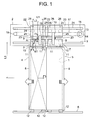
- Figure 1 is a front elevation that shows an elevator door apparatus according to Embodiment 1 of the present invention.
- a car doorway (an elevator doorway) 1 is disposed on a car (not shown).
- a hanger case 2 that is disposed above the car doorway 1 is also fixed to the car.
- a door rail (a supporting rail) 3 that is disposed parallel to a direction of frontage of the car doorway 1 is fixed to the hanger case 2.
- a pair of car doors (elevator doors) 4 and 5 that open and close the car doorway 1 are suspended on the door rail 3.
- Each of the car doors 4 and 5 is movable in the direction of frontage of the car doorway 1.
- the car doorway 1 is closed by each of the car doors 4 and 5 being placed in contact with each other, and opened by contact between each of the car doors 4 and 5 being separated.
- a car doorsill 6 that is disposed so as to be parallel to the direction of frontage of the car doorway 1 is fixed to a lower portion of the car doorway 1.
- a doorsill groove (not shown) is disposed on the car doorsill 6 so as to be parallel to directions of movement of each of the car doors 4 and 5.
- Each of the car doors 4 and 5 has: a door hanger 7 that is movable along the door rail 3; and a door panel 8 that is disposed on a lower portion of the door hanger 7 and that opens and closes the car doorway 1 by moving together with the door hanger 7.
- Each of the door hangers 7 has: a plurality of hanger rollers (contacting bodies) 9 (in this example, two) that are disposed so as to be spaced apart parallel to the door rail 3; and a shared door hanger main body (a hanger plate) 10 on which each of the hanger rollers 9 is disposed.
- Each of the hanger rollers 9 is placed on the door rail 3. Each of the hanger rollers 9 is rolled in contact with the door rail 3 when the door hangers 7 are moved along the door rail 3.
- Each of the door hanger main bodies 10 is disposed so as to avoid the door rail 3.
- a plurality of upthrust rollers 11 (in this example, two) for preventing dislodging of each of the hanger rollers 9 from the door rail 3 are disposed together with each of the hanger rollers 9 on each of the door hanger main bodies 10.
- Each of the upthrust rollers 11 is disposed below the door rail 3, and is disposed at a position that is similar to that of each of the hanger rollers 9 in a direction that is parallel to the door rail 3.
- a clearance is also disposed between each of the upthrust rollers 11 and the door rail 3.
- each of the hanger rollers 9 and each of the upthrust rollers 11 are disposed between the hanger case 2 and the door hanger main bodies 10.
- a plurality of door feet 12 (in this example, two) that are inserted into the doorsill groove of the car doorsill 6 are disposed on a lower portion of each of the door panels 8. Each of the door feet 12 is disposed so as to be spaced apart along the doorsill groove.
- a door driving apparatus 13 is disposed on a first end portion of the hanger case 2 in the direction of frontage.
- the door driving apparatus 13 has: a door driving apparatus main body 14 that includes a motor; and a driving pulley 15 that is rotated by a driving force from the door driving apparatus main body 14.
- a return pulley 16 is disposed on a second end portion of the hanger case 2 in the direction of frontage.
- An endless belt (a transmission belt body) 17 is wound around the driving pulley 15 and the return pulley 16.
- the belt 17 is moved cyclically by rotation of the driving pulley 15.
- the return pulley 16 is rotated by the cyclic movement of the belt 17.
- Each of the car doors 4 and 5 is connected to the belt 17 by means of coupling members 18 and 19, respectively, so as to be moved in opposite directions from each other by the cyclic movement of the belt 17.
- a door inclination arrester 20 for preventing each of the car doors 4 and 5 from inclining is supported by the hanger case 2.
- the door inclination arrester 20 is disposed above the door rail 3.
- the door inclination arrester 20 forces each of the door hangers 7 in a direction in which each of the hanger rollers 9 is pressed onto the door rail 3.
- the door inclination arrester 20 has: a guide rail 21 that is disposed so as to be parallel to the door rail 3; a plurality of facing hangers (facing moving bodies) 22 (in this example, two) that are movable along the guide rail 21 while facing the door hanger main bodies 10 in a vertical direction; and a plurality of forcing springs (forcing bodies) 23 (in this example, two) that are disposed between each of the facing hangers 22 and each of the door hangers 7, and that force each of the door hangers 7 away from each of the facing hangers 22, that is, downward.
- the guide rail 21 is fixed to the hanger case 2. Consequently, the guide rail 21 will not be displaced relative to the door rail 3.
- the guide rail 21 is also disposed so as to have a predetermined spacing relative to the door rail 3.
- a length of the guide rail 21 is made approximately identical to a length of the door rail 3.
- Each of the facing hangers 22 has: a plurality of guide rollers 24 (in this example, two) that are disposed so as to be spaced apart along the guide rail 21; and a shared facing hanger main body (a facing member) 25 on which each of the guide rollers 24 is disposed.
- Each of the guide rollers 24 is disposed below the guide rail 21. Each of the guide rollers 24 is forced upward by a forcing spring 23. Each of the guide rollers 24 is thereby pressed onto the guide rail 21. Each of the guide rollers 24 is rolled in contact with the guide rail 21 when the facing hangers 22 are moved along the guide rail 21.
- the facing hanger main bodies 25 are disposed so as to avoid the guide rail 21.
- a plurality of dislodgment preventing rollers 26 (in this example, two) for preventing dislodging of each of the guide rollers 24 from the guide rail 21 are disposed together with each of the guide rollers 24 on the facing hanger main bodies 25.
- Each of the dislodgment preventing rollers 26 is disposed above the guide rail 21, and is disposed at a position that is similar to that of each of the guide rollers 24 in a direction that is parallel to the guide rail 21.
- a clearance is also disposed between each of the dislodgment preventing rollers 26 and the guide rail 21.
- each of the guide rollers 24 and each of the dislodgment preventing rollers 26 are disposed between the hanger case 2 and the facing hanger main bodies 25.
- the forcing springs 23 are disposed between the door hanger main bodies 10 and the facing hanger main bodies 25 in a compressed state. In other words, the door hangers 7 and the facing hangers 22 are forced away from each other by the forcing springs 23.
- the forcing springs 23 are disposed between first hanger rollers 9 and second hanger rollers 9 in a direction that is parallel to the door rail 3. Consequently, even if clearance between the door hanger main bodies 10 and the facing hanger main bodies 25 fluctuates with the movement of the car doors 4 and 5, the door hangers 7 and the facing hangers 22 are prevented from jamming between the door rail 3 and the guide rail 21 by the elasticity of the forcing springs 23.
- the facing hangers 22 are forced in a direction in which each of the guide rollers 24 is pressed onto the guide rail 21 by receiving elastic repulsive force (spring force) from the forcing springs 23.
- the door hangers 7 are forced in a direction in which each of the hanger rollers 9 is pressed onto the door rail 3 by receiving elastic repulsive force (spring force) from the forcing springs 23.
- Each of the facing hangers 22 faces a door hanger 7 while being moved parallel to the guide rail 21 together with each of the car doors 4 and 5.
- Each of the door hangers 7 thereby receive downward spring force from the forcing springs 23 while being moved.
- Each of the hanger rollers 9 is thereby pressed onto the door rail 3 while being rolled on the door rail 3.
- gravitational force F1 acts downward on each of the hanger rollers 9 that are disposed on the car door 4 due to deadweight from the car door 4. If W is mass of the car door 4, magnitude of the gravitational force F1 can be expressed by Expression (1) below because there are two hanger rollers 9:
- the door hanger 7 is also subjected to a downward spring force F2 from the forcing springs 23.
- an inertial force F3 in the door closing direction acts on a center of gravity of the car door 4 due to acceleration or deceleration of the car door 4, for example, a moment M1 in which a moment due to the gravitational force F1, a moment due to the spring force F2, and a moment due to the inertial force F3 are combined will act on Contact Point A between the first hanger roller 9 (near an opening side of the door) and the door rail 3.
- the moment M1 can be expressed by Expression (2) below:
- M ⁇ 1 F ⁇ 1 ⁇ L ⁇ 1 + F ⁇ 2 ⁇ L ⁇ 2 - F ⁇ 3 ⁇ L ⁇ 3
- L1 is a distance in a horizontal direction from Contact Point A to a central position of the second hanger roller 9.
- L2 is a distance in the horizontal direction from Contact Point A to a position of a forcing spring 23.
- L3 is a distance in a height direction from Contact Point A to the center of gravity of the car door 4.
- the spring force F2 and the distance L2 are adjusted in such a way that the moment M1 is greater than or equal to zero.
- the moment M1 can be prevented from being less than zero, and the car door 4 can be prevented from being inclined.
- each of the car doors 4 and 5 can also be prevented from inclining during the opening and closing of the car doorway 1. Because a link mechanism is not used as in the related art, inclination of each of the car doors 4 and 5 can prevented by a simple configuration, enabling reductions in manufacturing costs.
- the door inclination arrester 20 has: a guide rail 21 that is disposed so as to be parallel to the door rail 3; facing hangers 22 that are movable along the guide rail 21 while facing the door hanger main bodies 10; and forcing springs 23 that are disposed between the facing hangers 22 and the door main bodies 10, and that force the door main bodies 10 away from the facing hangers 22, inclination of each of the car doors 4 and 5 can prevented by a simple configuration. Even if clearance between the facing hangers 22 and the door hanger main bodies 10 fluctuates with the movement of the car doors 4 and 5, the facing hangers 22 and the door hangers 7 can be prevented from jamming between the door rail 3 and the guide rail 21 by the elasticity of the forcing springs 23. Consequently, improvements in reliability of the action of the door inclination arrester 20 can be achieved.
- each of the hanger rollers 9 are rolled in contact with the door rail 3 when the door hangers 7 are moved along the door rail 3, the door hangers 7 can be moved along the door rail 3 smoothly.
- the number of forcing springs 23 that are disposed between the door hanger main bodies 10 and the facing hanger main bodies 25 is one for each of the respective car doors 4 and 5, but a plurality of forcing springs 23 may also be disposed between the door hanger main bodies 10 and the facing hanger main bodies 25. In that case, each of the forcing springs 23 can be disposed so as to be spaced apart along the door rail 3.
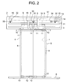
- FIG. 2 is a front elevation that shows an elevator door apparatus according to Embodiment 2 of the present invention.
- a displacing rail (a displacing body) 31 that is displaceable vertically relative to a door rail 3 is disposed above the door rail 3 so as to be parallel to the door rail 3.
- a length of the displacing rail 31 is approximately identical to a length of the door rail 3.
- a plurality of spring bearing portions 32 (in this example, three) that are fixed to a hanger case 2 are disposed above the displacing rail 31.
- Each of the spring bearing portions 32 is disposed so as to be spaced apart along the door rail 3.
- Forcing springs (forcing bodies) 33 that force the displacing rail 31 toward the door rail 3 (downward) are respectively disposed between each of the spring bearing portions 32 and the displacing rail 31.
- Each of the forcing springs 33 is disposed between the spring bearing portions 32 and the displacing rail 31 in a compressed state.
- the displacing rail 31 contacts upper portions of respective hanger rollers 9.
- Each of the hanger rollers 9 is pushed downward by the displacing rail 31, which is forced by each of the forcing springs 33.
- each of the hanger rollers 9 is subjected to the downward force of each of the forcing springs 33 by means of the displacing rail 31.
- Each of the hanger rollers 9 is movable along the door rail 3 while being pushed by the displacing rail 31.
- Door hangers 7 are forced in a direction in which each of the hanger rollers 9 is pressed onto the door rail 3 due to each of the hanger rollers 9 being pushed by the displacing rail 31 (in other words, due to each of the hanger rollers 9 being subjected to a spring force from each of the forcing springs 33 by means of the displacing rail 31).
- a door inclination arrester 34 includes the displacing rail 31, each of the spring bearing portions 32, and each of the forcing springs 33. The rest of the configuration is similar to that of Embodiment 1.
- Each of the hanger rollers 9 is pushed downward by the displacing rail 31, which is forced by each of the forcing springs 33. Each of the hanger rollers 9 is thereby pressed onto the door rail 3.
- each of the hanger rollers 9 is rolled on the door rail 3 while sliding relative to the displacing rail 31 while continuously being subjected to a pressing force from the displacing rail 31.
- the displacing rail 31 is displaced vertically with each of the door hangers 7 while pushing each of the hanger rollers 9 downward.
- the door inclination arrester 34 has: a displacing rail 31 that is displaceable relative to the door rail 3; and forcing springs 33 that force the displacing rail 31 toward the door rail 3, and each of the hanger rollers 9 is pressed onto the door rail 3 by being pushed by the displacing rail 31, similar effects to those of Embodiment 1 are exhibited, and the number of parts in the door inclination arrester 34 can also be reduced, enabling the construction to be simplified further. Consequently, further reductions in manufacturing costs and reductions in the size of the door apparatus can be achieved.
- the displacing rail and the door rail 3 must be made exactly parallel in order to prevent each of the hanger rollers 9 from jamming between the door rail 3 and the displacing rail, it is necessary to increase milling precision and installation precision of the displacing rail and the door rail 3, increasing manufacturing costs, and also lengthening the amount of assembly time.
- each of the hanger rollers 9 can be prevented from jamming between the displacing rail 31 and the door rail 3, enabling reliability of the action to be improved. Because it is also not necessary to increase the milling precision or the installation precision of the displacing rail 31 excessively, reductions in manufacturing costs and shortening of the amount of assembly time, etc., can also be achieved.
- FIG. 3 is a front elevation that shows an elevator door apparatus according to Embodiment 3 of the present invention.
- protruding rollers (transmitting bodies) 41 that contact a displacing rail 31 are disposed on respective door hanger main bodies 10.
- the protruding rollers 41 are disposed at positions that are closer to the displacing rail 31 than respective hanger rollers 9. In other words, portions of the protruding rollers 41 protrude toward the displacing rail 31 more than each of the hanger rollers 9.
- each of the protruding rollers 41 contacts the displacing rail 31 and is separated from the door rail 3.
- Each of the hanger rollers 9 contacts the door rail 3 and is separated from the displacing rail 31.
- the protruding rollers 41 are disposed between each of the hanger rollers 9 in a horizontal direction.
- the protruding rollers 41 are pushed downward by the displacing rail 31, which is forced by each of the forcing springs 33.
- the protruding rollers 41 are subjected to the downward force of each of the forcing springs 33 by means of the displacing rail 31.
- the protruding rollers 41 are movable together with the door hangers 7 while being pushed by the displacing rail 31.
- the door hangers 7 are forced in a direction in which each of the hanger rollers 9 is pressed onto the door rail 3 by the protruding rollers 41 being pushed by the displacing rail 31.
- each of the hanger rollers 9 is pressed onto the door rail 3 by the protruding rollers 41 being subjected to a spring force from each of the forcing springs 33 by means of the displacing rail 31.
- a door inclination arrester 42 includes the displacing rail 31, each of the spring bearing portions 32, each of the forcing springs 33, and each of the protruding rollers 41.
- the rest of the configuration is similar to that of Embodiment 2.
- each of the protruding rollers 41 is rolled in contact with the displacing rail 31 while continuously being subjected to a pressing force from the displacing rail 31.
- each of the protruding rollers 41 is moved together with a door hanger 7 while being pushed downward by the displacing rail 31.
- the displacing rail 31 is displaced vertically with each of the door hangers 7 while pushing each of the protruding rollers 41 downward.
- the number of protruding rollers 41 is one for each of the respective car doors 4 and 5, but a plurality of protruding rollers 41 may also be disposed on the door hanger main bodies 10. In that case, each of the protruding rollers 41 can be disposed so as to be spaced apart along the door rail 3 between each of the hanger rollers 9.
- the present invention is applied to an elevator door apparatus that has car doors 4 and 5 that open and close a car doorway 1, but the present invention may also be applied to an elevator door apparatus that has landing doors (elevator doors) that open and close a landing doorway (an elevator doorway).
Landscapes
- Engineering & Computer Science (AREA)
- Mechanical Engineering (AREA)
- Elevator Door Apparatuses (AREA)
Abstract
Description
- The present invention relates to an elevator door apparatus that opens and closes an elevator doorway.
- Conventionally, elevator door opening and closing apparatuses have been proposed in which a door machine that is disposed above a sliding door is disposed close to the sliding door in order to prevent swinging of the sliding door during opening and closing and during reversal. A pulley that is rotated by receiving power from an electric motor is disposed above the sliding door. The door machine is constituted by a link mechanism that changes the rotation of the pulley into reciprocation of the sliding door. An arm that suspends the sliding door is connected to the door machine. By disposing the door machine close to the sliding door, the length of the arm can be shortened, enabling stabilization of support of the sliding door to be achieved (See Patent Literature 1).
- Japanese Patent Laid-Open No.
HEI 6-80361 - However, if acceleration and deceleration of the sliding door are increased further by increasing opening and closing speeds, there is a risk that it will no longer be possible to suppress displacement of the sliding door due to inertial force during acceleration and deceleration even if the distance between the sliding door and the door machine is reduced. Consequently, there is a risk that the sliding door will incline during acceleration and deceleration of the sliding door.
- Because the door machine is constituted by a link mechanism, the construction is complicated. Thus, manufacturing costs are also increased.
- The present invention aims to solve the above problems and an object of the present invention is to provide an elevator door apparatus that enables increases in opening and closing speeds of an elevator doorway to be achieved, that enables an elevator door to be prevented from inclining during the opening and closing of the elevator doorway, and that also enables reductions in manufacturing costs.
- In order to achieve the above object, according to one aspect of the present invention, there is provided an elevator door apparatus characterized in including: a door rail that is disposed above an elevator doorway, and that is disposed parallel to a direction of frontage of the elevator doorway; a door hanger that has: a plurality of contacting bodies that are each placed on the door rail, and that are disposed so as to be spaced apart along the door rail; and a shared door hanger main body on which each of the contacting bodies is disposed, the door hanger being movable along the door rail such that each of the contacting bodies contacts the door rail; a door panel that is disposed on the door hanger main body, and that opens and closes the elevator doorway by being moved together with the door hanger; and a door inclination arrester that is disposed above the door rail, and that forces the door hanger in a direction in which each of the contacting bodies is pressed onto the door rail.
-
-
Figure 1 is a front elevation that shows an elevator door apparatus according toEmbodiment 1 of the present invention; -
Figure 2 is a front elevation that shows an elevator door apparatus according toEmbodiment 2 of the present invention; and -
Figure 3 is a front elevation that shows an elevator door apparatus according toEmbodiment 3 of the present invention. - Preferred embodiments of the present invention will now be explained with reference to the drawings.
-
Figure 1 is a front elevation that shows an elevator door apparatus according toEmbodiment 1 of the present invention. In the figure, a car doorway (an elevator doorway) 1 is disposed on a car (not shown). Ahanger case 2 that is disposed above thecar doorway 1 is also fixed to the car. - A door rail (a supporting rail) 3 that is disposed parallel to a direction of frontage of the
car doorway 1 is fixed to thehanger case 2. A pair of car doors (elevator doors) 4 and 5 that open and close thecar doorway 1 are suspended on thedoor rail 3. - Each of the
car doors car doorway 1. Thecar doorway 1 is closed by each of thecar doors car doors - A
car doorsill 6 that is disposed so as to be parallel to the direction of frontage of thecar doorway 1 is fixed to a lower portion of thecar doorway 1. A doorsill groove (not shown) is disposed on thecar doorsill 6 so as to be parallel to directions of movement of each of thecar doors - Each of the
car doors door hanger 7 that is movable along thedoor rail 3; and adoor panel 8 that is disposed on a lower portion of thedoor hanger 7 and that opens and closes thecar doorway 1 by moving together with thedoor hanger 7. - Each of the
door hangers 7 has: a plurality of hanger rollers (contacting bodies) 9 (in this example, two) that are disposed so as to be spaced apart parallel to thedoor rail 3; and a shared door hanger main body (a hanger plate) 10 on which each of thehanger rollers 9 is disposed. - Each of the
hanger rollers 9 is placed on thedoor rail 3. Each of thehanger rollers 9 is rolled in contact with thedoor rail 3 when thedoor hangers 7 are moved along thedoor rail 3. - Each of the door hanger
main bodies 10 is disposed so as to avoid thedoor rail 3. A plurality of upthrust rollers 11 (in this example, two) for preventing dislodging of each of thehanger rollers 9 from thedoor rail 3 are disposed together with each of thehanger rollers 9 on each of the door hangermain bodies 10. Each of theupthrust rollers 11 is disposed below thedoor rail 3, and is disposed at a position that is similar to that of each of thehanger rollers 9 in a direction that is parallel to thedoor rail 3. A clearance is also disposed between each of theupthrust rollers 11 and thedoor rail 3. In addition, each of thehanger rollers 9 and each of theupthrust rollers 11 are disposed between thehanger case 2 and the door hangermain bodies 10. - A plurality of door feet 12 (in this example, two) that are inserted into the doorsill groove of the
car doorsill 6 are disposed on a lower portion of each of thedoor panels 8. Each of thedoor feet 12 is disposed so as to be spaced apart along the doorsill groove. - A
door driving apparatus 13 is disposed on a first end portion of thehanger case 2 in the direction of frontage. Thedoor driving apparatus 13 has: a door driving apparatusmain body 14 that includes a motor; and adriving pulley 15 that is rotated by a driving force from the door driving apparatusmain body 14. Areturn pulley 16 is disposed on a second end portion of thehanger case 2 in the direction of frontage. - An endless belt (a transmission belt body) 17 is wound around the driving
pulley 15 and thereturn pulley 16. Thebelt 17 is moved cyclically by rotation of thedriving pulley 15. Thereturn pulley 16 is rotated by the cyclic movement of thebelt 17. - Each of the
car doors belt 17 by means ofcoupling members belt 17. - A door inclination arrester 20 for preventing each of the
car doors hanger case 2. Thedoor inclination arrester 20 is disposed above thedoor rail 3. The door inclination arrester 20 forces each of thedoor hangers 7 in a direction in which each of thehanger rollers 9 is pressed onto thedoor rail 3. - The
door inclination arrester 20 has: aguide rail 21 that is disposed so as to be parallel to thedoor rail 3; a plurality of facing hangers (facing moving bodies) 22 (in this example, two) that are movable along theguide rail 21 while facing the door hangermain bodies 10 in a vertical direction; and a plurality of forcing springs (forcing bodies) 23 (in this example, two) that are disposed between each of the facinghangers 22 and each of thedoor hangers 7, and that force each of thedoor hangers 7 away from each of the facinghangers 22, that is, downward. - The
guide rail 21 is fixed to thehanger case 2. Consequently, theguide rail 21 will not be displaced relative to thedoor rail 3. Theguide rail 21 is also disposed so as to have a predetermined spacing relative to thedoor rail 3. In addition, a length of theguide rail 21 is made approximately identical to a length of thedoor rail 3. - Each of the facing
hangers 22 has: a plurality of guide rollers 24 (in this example, two) that are disposed so as to be spaced apart along theguide rail 21; and a shared facing hanger main body (a facing member) 25 on which each of theguide rollers 24 is disposed. - Each of the
guide rollers 24 is disposed below theguide rail 21. Each of theguide rollers 24 is forced upward by a forcingspring 23. Each of theguide rollers 24 is thereby pressed onto theguide rail 21. Each of theguide rollers 24 is rolled in contact with theguide rail 21 when the facinghangers 22 are moved along theguide rail 21. - The facing hanger
main bodies 25 are disposed so as to avoid theguide rail 21. A plurality of dislodgment preventing rollers 26 (in this example, two) for preventing dislodging of each of theguide rollers 24 from theguide rail 21 are disposed together with each of theguide rollers 24 on the facing hangermain bodies 25. Each of thedislodgment preventing rollers 26 is disposed above theguide rail 21, and is disposed at a position that is similar to that of each of theguide rollers 24 in a direction that is parallel to theguide rail 21. A clearance is also disposed between each of thedislodgment preventing rollers 26 and theguide rail 21. In addition, each of theguide rollers 24 and each of thedislodgment preventing rollers 26 are disposed between thehanger case 2 and the facing hangermain bodies 25. - The forcing springs 23 are disposed between the door hanger
main bodies 10 and the facing hangermain bodies 25 in a compressed state. In other words, thedoor hangers 7 and the facinghangers 22 are forced away from each other by the forcing springs 23. The forcing springs 23 are disposed betweenfirst hanger rollers 9 andsecond hanger rollers 9 in a direction that is parallel to thedoor rail 3. Consequently, even if clearance between the door hangermain bodies 10 and the facing hangermain bodies 25 fluctuates with the movement of thecar doors door hangers 7 and the facinghangers 22 are prevented from jamming between thedoor rail 3 and theguide rail 21 by the elasticity of the forcing springs 23. - The facing
hangers 22 are forced in a direction in which each of theguide rollers 24 is pressed onto theguide rail 21 by receiving elastic repulsive force (spring force) from the forcing springs 23. Thedoor hangers 7 are forced in a direction in which each of thehanger rollers 9 is pressed onto thedoor rail 3 by receiving elastic repulsive force (spring force) from the forcing springs 23. - Next, action will be explained. When the driving
pulley 15 is rotated by a driving force from thedoor driving apparatus 13, thebelt 17 is moved cyclically. Each of thecar doors car doorway 1. Thecar doorway 1 is thereby opened and closed. - Each of the facing
hangers 22 faces adoor hanger 7 while being moved parallel to theguide rail 21 together with each of thecar doors door hangers 7 thereby receive downward spring force from the forcingsprings 23 while being moved. Each of thehanger rollers 9 is thereby pressed onto thedoor rail 3 while being rolled on thedoor rail 3. - When the
car doors 4 are accelerated or decelerated during opening and closing of thecar doorway 1 and inertial force due to acceleration or deceleration acts on thecar doors 4, thecar door 4 will try to incline relative to thedoor rail 3 due to being subjected to the inertial force. However, because thedoor hangers 7 are strongly forced by the forcingsprings 23 in a direction that presses each of thehanger rollers 9 onto thedoor rail 3, thehanger rollers 9 are prevented from separating upward from thedoor rail 3. Thecar doors 4 are thereby prevented from being inclined. - Specifically, gravitational force F1 acts downward on each of the
hanger rollers 9 that are disposed on thecar door 4 due to deadweight from thecar door 4. If W is mass of thecar door 4, magnitude of the gravitational force F1 can be expressed by Expression (1) below because there are two hanger rollers 9: -

- The
door hanger 7 is also subjected to a downward spring force F2 from the forcing springs 23. - Consequently, if an inertial force F3 in the door closing direction acts on a center of gravity of the
car door 4 due to acceleration or deceleration of thecar door 4, for example, a moment M1 in which a moment due to the gravitational force F1, a moment due to the spring force F2, and a moment due to the inertial force F3 are combined will act on Contact Point A between the first hanger roller 9 (near an opening side of the door) and thedoor rail 3. The moment M1 can be expressed by Expression (2) below: -

- Here, L1 is a distance in a horizontal direction from Contact Point A to a central position of the
second hanger roller 9. L2 is a distance in the horizontal direction from Contact Point A to a position of a forcingspring 23. L3 is a distance in a height direction from Contact Point A to the center of gravity of thecar door 4. - In Expression (2), the directions of the moments (F1·L1 + F2·L2) due the gravitational force F1 and the spring force F2, respectively, are opposite to the direction of the inertia moment of force (F3·L3) that tries to make the
car door 4 incline. - Consequently, if the moment M1 is greater than or equal to zero, the
car door 4 will not be inclined relative to thedoor rail 3, and none of thehanger rollers 9 will be separated upward from thedoor rail 3 because the moments that are due to the gravitational force F1 and the spring force F2, respectively, are greater than or equal to the moment that is due to the inertial force F3. - If, however, the moment M1 is less than zero, the
car door 4 will be inclined relative to thedoor rail 3, and thesecond hanger roller 9 will be separated upward from thedoor rail 3, because the moment that is due to the inertial force F3 will exceed the moments that are due to the gravitational force F1 and the spring force F2, respectively. - Because the moment that is due to the forcing
springs 23 is a moment that opposes the moment that is due to the inertial force F3, the spring force F2 and the distance L2 are adjusted in such a way that the moment M1 is greater than or equal to zero. Thus, even if thecar door 4 is accelerated or decelerated, the moment M1 can be prevented from being less than zero, and thecar door 4 can be prevented from being inclined. - Moreover, similar adjustments are also made to the forcing
springs 23 of thecar door 5, enabling thecar door 5 to be prevented from being inclined. - In an elevator door apparatus of this kind, because the
door hangers 7 are forced by thedoor inclination arrester 20 in a direction in which each of thehanger rollers 9 is pressed onto thedoor rail 3, thedoor hangers 7 can be forced in a direction in which inclination of each of thecar doors car doors car doors door inclination arrester 20 against thedoor hangers 7 from being inclined even if the acceleration and deceleration of each of thecar doors car doorway 1 can be achieved, and each of thecar doors car doorway 1. Because a link mechanism is not used as in the related art, inclination of each of thecar doors - Because the
door inclination arrester 20 has: aguide rail 21 that is disposed so as to be parallel to thedoor rail 3; facinghangers 22 that are movable along theguide rail 21 while facing the door hangermain bodies 10; and forcingsprings 23 that are disposed between the facinghangers 22 and the doormain bodies 10, and that force the doormain bodies 10 away from the facinghangers 22, inclination of each of thecar doors hangers 22 and the door hangermain bodies 10 fluctuates with the movement of thecar doors hangers 22 and thedoor hangers 7 can be prevented from jamming between thedoor rail 3 and theguide rail 21 by the elasticity of the forcing springs 23. Consequently, improvements in reliability of the action of thedoor inclination arrester 20 can be achieved. - Because each of the
hanger rollers 9 are rolled in contact with thedoor rail 3 when thedoor hangers 7 are moved along thedoor rail 3, thedoor hangers 7 can be moved along thedoor rail 3 smoothly. - Moreover, in the above example, the number of forcing
springs 23 that are disposed between the door hangermain bodies 10 and the facing hangermain bodies 25 is one for each of therespective car doors springs 23 may also be disposed between the door hangermain bodies 10 and the facing hangermain bodies 25. In that case, each of the forcingsprings 23 can be disposed so as to be spaced apart along thedoor rail 3. -
Figure 2 is a front elevation that shows an elevator door apparatus according toEmbodiment 2 of the present invention. In the figure, a displacing rail (a displacing body) 31 that is displaceable vertically relative to adoor rail 3 is disposed above thedoor rail 3 so as to be parallel to thedoor rail 3. A length of the displacingrail 31 is approximately identical to a length of thedoor rail 3. - A plurality of spring bearing portions 32 (in this example, three) that are fixed to a
hanger case 2 are disposed above the displacingrail 31. Each of thespring bearing portions 32 is disposed so as to be spaced apart along thedoor rail 3. - Forcing springs (forcing bodies) 33 that force the displacing
rail 31 toward the door rail 3 (downward) are respectively disposed between each of thespring bearing portions 32 and the displacingrail 31. Each of the forcingsprings 33 is disposed between thespring bearing portions 32 and the displacingrail 31 in a compressed state. - The displacing
rail 31 contacts upper portions ofrespective hanger rollers 9. Each of thehanger rollers 9 is pushed downward by the displacingrail 31, which is forced by each of the forcing springs 33. Specifically, each of thehanger rollers 9 is subjected to the downward force of each of the forcingsprings 33 by means of the displacingrail 31. Each of thehanger rollers 9 is movable along thedoor rail 3 while being pushed by the displacingrail 31. -
Door hangers 7 are forced in a direction in which each of thehanger rollers 9 is pressed onto thedoor rail 3 due to each of thehanger rollers 9 being pushed by the displacing rail 31 (in other words, due to each of thehanger rollers 9 being subjected to a spring force from each of the forcingsprings 33 by means of the displacing rail 31). - Moreover, a
door inclination arrester 34 includes the displacingrail 31, each of thespring bearing portions 32, and each of the forcing springs 33. The rest of the configuration is similar to that ofEmbodiment 1. - Next, action of the
door inclination arrester 34 will be explained. Each of thehanger rollers 9 is pushed downward by the displacingrail 31, which is forced by each of the forcing springs 33. Each of thehanger rollers 9 is thereby pressed onto thedoor rail 3. - When the
car doors hanger rollers 9 is rolled on thedoor rail 3 while sliding relative to the displacingrail 31 while continuously being subjected to a pressing force from the displacingrail 31. - If any of the
door hangers 7 is displaced vertically due to irregularities, etc., on thedoor rail 3, the displacingrail 31 is displaced vertically with each of thedoor hangers 7 while pushing each of thehanger rollers 9 downward. - In an elevator door apparatus of this kind, because the
door inclination arrester 34 has: a displacingrail 31 that is displaceable relative to thedoor rail 3; and forcingsprings 33 that force the displacingrail 31 toward thedoor rail 3, and each of thehanger rollers 9 is pressed onto thedoor rail 3 by being pushed by the displacingrail 31, similar effects to those ofEmbodiment 1 are exhibited, and the number of parts in thedoor inclination arrester 34 can also be reduced, enabling the construction to be simplified further. Consequently, further reductions in manufacturing costs and reductions in the size of the door apparatus can be achieved. - Now, adopting a configuration in which a displacing rail is fixed to the
hanger case 2 and each of thehanger rollers 9 is held from opposite sides between thedoor rail 3 and the displacing rail is also conceivable, but in that kind of construction if the displacing rail is inclined even slightly relative to thehanger case 2, there is a risk that each of thehanger rollers 9 will jam between thedoor rail 3 and the displacing rail as they move along thedoor rail 3. Because the displacing rail and thedoor rail 3 must be made exactly parallel in order to prevent each of thehanger rollers 9 from jamming between thedoor rail 3 and the displacing rail, it is necessary to increase milling precision and installation precision of the displacing rail and thedoor rail 3, increasing manufacturing costs, and also lengthening the amount of assembly time. - In the
door inclination arrester 34, because the displacingrail 31 is displaceable relative to thedoor rail 3, each of thehanger rollers 9 can be prevented from jamming between the displacingrail 31 and thedoor rail 3, enabling reliability of the action to be improved. Because it is also not necessary to increase the milling precision or the installation precision of the displacingrail 31 excessively, reductions in manufacturing costs and shortening of the amount of assembly time, etc., can also be achieved. -
Figure 3 is a front elevation that shows an elevator door apparatus according toEmbodiment 3 of the present invention. In the figure, protruding rollers (transmitting bodies) 41 that contact a displacingrail 31 are disposed on respective door hangermain bodies 10. The protrudingrollers 41 are disposed at positions that are closer to the displacingrail 31 thanrespective hanger rollers 9. In other words, portions of the protrudingrollers 41 protrude toward the displacingrail 31 more than each of thehanger rollers 9. Thus, each of the protrudingrollers 41 contacts the displacingrail 31 and is separated from thedoor rail 3. Each of thehanger rollers 9 contacts thedoor rail 3 and is separated from the displacingrail 31. - The protruding
rollers 41 are disposed between each of thehanger rollers 9 in a horizontal direction. The protrudingrollers 41 are pushed downward by the displacingrail 31, which is forced by each of the forcing springs 33. Specifically, the protrudingrollers 41 are subjected to the downward force of each of the forcingsprings 33 by means of the displacingrail 31. The protrudingrollers 41 are movable together with thedoor hangers 7 while being pushed by the displacingrail 31. - The
door hangers 7 are forced in a direction in which each of thehanger rollers 9 is pressed onto thedoor rail 3 by the protrudingrollers 41 being pushed by the displacingrail 31. In other words, each of thehanger rollers 9 is pressed onto thedoor rail 3 by the protrudingrollers 41 being subjected to a spring force from each of the forcingsprings 33 by means of the displacingrail 31. - Moreover, a
door inclination arrester 42 includes the displacingrail 31, each of thespring bearing portions 32, each of the forcingsprings 33, and each of the protrudingrollers 41. The rest of the configuration is similar to that ofEmbodiment 2. - Next, action of the
door inclination arrester 42 will be explained. Each of the protrudingrollers 41 is pushed downward by the displacingrail 31, which is forced by each of the forcing springs 33. Each of thehanger rollers 9 is thereby pressed onto thedoor rail 3. - When the
car doors rollers 41 is rolled in contact with the displacingrail 31 while continuously being subjected to a pressing force from the displacingrail 31. In other words, when thecar doors rollers 41 is moved together with adoor hanger 7 while being pushed downward by the displacingrail 31. - If any of the
door hangers 7 is displaced vertically due to irregularities, etc., on thedoor rail 3, the displacingrail 31 is displaced vertically with each of thedoor hangers 7 while pushing each of the protrudingrollers 41 downward. - In an elevator door apparatus of this kind, because protruding
rollers 41 that are pushed downward by the displacingrail 31 are disposed on the door hangermain bodies 10, and the protrudingrollers 41 are disposed in positions that are closer to the displacingrail 31 than each of thehanger rollers 9, similar effects to those ofEmbodiment 1 are exhibited, and the displacingrail 31 can also be prevented from contacting each of thehanger rollers 9. Thus, resistance that thedoor hangers 7 are subjected to from the displacingrail 31 when thedoor hangers 7 move along thedoor rail 3 can be reduced. Consequently, the spring force from each of the forcingsprings 33 can be increased, enabling each of thecar doors car doorway 1. - Moreover, in the above example, the number of protruding
rollers 41 is one for each of therespective car doors rollers 41 may also be disposed on the door hangermain bodies 10. In that case, each of the protrudingrollers 41 can be disposed so as to be spaced apart along thedoor rail 3 between each of thehanger rollers 9. - In each of the above embodiments, the present invention is applied to an elevator door apparatus that has
car doors car doorway 1, but the present invention may also be applied to an elevator door apparatus that has landing doors (elevator doors) that open and close a landing doorway (an elevator doorway).
Claims (5)
- An elevator door apparatus characterized in comprising:a door rail that is disposed above an elevator doorway, and that is disposed parallel to a direction of frontage of the elevator doorway;a door hanger that has:a plurality of contacting bodies that are each placed on the door rail, and that are disposed so as to be spaced apart along the door rail; anda shared door hanger main body on which each of the contacting bodies is disposed,the door hanger being movable along the door rail such that each of the contacting bodies contacts the door rail;a door panel that is disposed on the door hanger main body, and that opens and closes the elevator doorway by being moved together with the door hanger; anda door inclination arrester that is disposed above the door rail, and that forces the door hanger in a direction in which each of the contacting bodies is pressed onto the door rail.
- An elevator door apparatus according to Claim 1, characterized in that:the door inclination arrester comprises:a guide rail that is disposed so as to be parallel to the door rail;a facing moving body that is movable along the guide rail while facing the door hanger main body; anda forcing body that is disposed between the facing moving body and the door hanger main body, and that forces the door hanger main body away from the facing moving body; andthe door hanger is forced in a direction in which each of the contacting bodies is pressed onto the door rail by the door hanger main body being forced by the forcing body.
- An elevator door apparatus according to Claim 1, characterized in that:the door inclination arrester comprises:a displacing body that is disposed so as to be parallel to the door rail, and that is displaceable relative to the door rail; anda forcing body that forces the displacing body toward the door rail;each of the contacting bodies is movable along the door rail while being pushed by the displacing body; andthe door hanger is forced in a direction in which each of the contacting bodies is pressed onto the door rail by each of the contacting bodies being pushed by the displacing body.
- An elevator door apparatus according to Claim 1, characterized in that:the door inclination arrester comprises:a displacing body that is disposed so as to be parallel to the door rail, and that is displaceable relative to the door rail;a forcing body that forces the displacing body toward the door rail; anda transmitting body that is disposed on the door hanger main body, and that is moved together with the door hanger while being pushed by the displacing body;the transmitting body is disposed in a position that is closer to the displacing body than the contacting bodies; andthe door hanger is forced in a direction in which each of the contacting bodies is pressed onto the door rail by the transmitting body being pushed by the displacing body.
- An elevator door apparatus according to any of Claims 1 through 4, characterized in that each of the contacting bodies is a hanger roller that is rolled on the door rail.
Applications Claiming Priority (1)
| Application Number | Priority Date | Filing Date | Title |
|---|---|---|---|
| PCT/JP2006/316730 WO2008023435A1 (en) | 2006-08-25 | 2006-08-25 | Door device for elevator |
Publications (2)
| Publication Number | Publication Date |
|---|---|
| EP2055663A1 true EP2055663A1 (en) | 2009-05-06 |
| EP2055663A4 EP2055663A4 (en) | 2013-06-05 |
Family
ID=39106529
Family Applications (1)
| Application Number | Title | Priority Date | Filing Date |
|---|---|---|---|
| EP06796803.2A Withdrawn EP2055663A4 (en) | 2006-08-25 | 2006-08-25 | DOOR DEVICE FOR ELEVATOR |
Country Status (5)
| Country | Link |
|---|---|
| EP (1) | EP2055663A4 (en) |
| JP (1) | JP4913145B2 (en) |
| KR (1) | KR101087322B1 (en) |
| CN (1) | CN101506085B (en) |
| WO (1) | WO2008023435A1 (en) |
Cited By (2)
| Publication number | Priority date | Publication date | Assignee | Title |
|---|---|---|---|---|
| CN103145023A (en) * | 2011-12-06 | 2013-06-12 | 株式会社日立制作所 | Entrance and exit device |
| WO2018114285A1 (en) * | 2016-12-21 | 2018-06-28 | Inventio Ag | Elevator cab having a movable cab door |
Families Citing this family (4)
| Publication number | Priority date | Publication date | Assignee | Title |
|---|---|---|---|---|
| CN102667042B (en) * | 2009-11-17 | 2015-06-10 | 纳博特斯克株式会社 | Door hanging apparatus and door apparatus provided with the same |
| EP2338823A1 (en) * | 2009-12-23 | 2011-06-29 | Inventio AG | Lift cabin |
| JP6109401B2 (en) * | 2014-02-19 | 2017-04-05 | 三菱電機株式会社 | Elevator door equipment |
| JP6617996B1 (en) * | 2019-03-25 | 2019-12-11 | フジテック株式会社 | Elevator door dropout prevention device |
Family Cites Families (11)
| Publication number | Priority date | Publication date | Assignee | Title |
|---|---|---|---|---|
| US1917415A (en) * | 1929-02-27 | 1933-07-11 | Woodruff Carl | Elevator door |
| JPS4320586Y1 (en) * | 1965-06-07 | 1968-08-30 | ||
| JPS58145970A (en) * | 1982-02-24 | 1983-08-31 | Konishiroku Photo Ind Co Ltd | Image forming device |
| JPS58145970U (en) * | 1982-03-29 | 1983-10-01 | 三菱電機株式会社 | Elevator door device |
| JP2616643B2 (en) | 1992-09-01 | 1997-06-04 | 三菱電機株式会社 | Elevator door opener |
| JP2845257B2 (en) * | 1993-08-30 | 1999-01-13 | 三菱電機株式会社 | Door device for elevator |
| JPH08245144A (en) * | 1995-03-10 | 1996-09-24 | Mitsubishi Denki Bill Techno Service Kk | Elevator door opening and closing device |
| JP2000026053A (en) * | 1998-07-09 | 2000-01-25 | Otis Elevator Co | Door opening/closing device for elevator |
| JP4531899B2 (en) * | 2001-06-06 | 2010-08-25 | 三菱電機株式会社 | Elevator car door device |
| JP2005104668A (en) * | 2003-09-30 | 2005-04-21 | Mitsubishi Electric Corp | Elevator door equipment |
| JP2006137518A (en) * | 2004-11-11 | 2006-06-01 | Mitsubishi Electric Corp | Elevator door device |
-
2006
- 2006-08-25 KR KR1020097003413A patent/KR101087322B1/en not_active Expired - Fee Related
- 2006-08-25 EP EP06796803.2A patent/EP2055663A4/en not_active Withdrawn
- 2006-08-25 WO PCT/JP2006/316730 patent/WO2008023435A1/en not_active Ceased
- 2006-08-25 CN CN2006800556694A patent/CN101506085B/en not_active Expired - Fee Related
- 2006-08-25 JP JP2008530788A patent/JP4913145B2/en not_active Expired - Fee Related
Cited By (3)
| Publication number | Priority date | Publication date | Assignee | Title |
|---|---|---|---|---|
| CN103145023A (en) * | 2011-12-06 | 2013-06-12 | 株式会社日立制作所 | Entrance and exit device |
| WO2018114285A1 (en) * | 2016-12-21 | 2018-06-28 | Inventio Ag | Elevator cab having a movable cab door |
| US11352236B2 (en) | 2016-12-21 | 2022-06-07 | Inventio Ag | Elevator car having a movable car door |
Also Published As
| Publication number | Publication date |
|---|---|
| WO2008023435A1 (en) | 2008-02-28 |
| KR20090038463A (en) | 2009-04-20 |
| EP2055663A4 (en) | 2013-06-05 |
| JPWO2008023435A1 (en) | 2010-01-07 |
| CN101506085A (en) | 2009-08-12 |
| CN101506085B (en) | 2011-04-27 |
| JP4913145B2 (en) | 2012-04-11 |
| KR101087322B1 (en) | 2011-11-25 |
Similar Documents
| Publication | Publication Date | Title |
|---|---|---|
| US20070295564A1 (en) | Door apparatus | |
| EP2426076B1 (en) | Elevator door device | |
| EP3560879B1 (en) | Gap-reducing sill assembly for an elevator car | |
| EP2055663A1 (en) | Door device for elevator | |
| EP1997767B1 (en) | Emergency stop device for elevator | |
| KR20220124162A (en) | door operator system | |
| CN101456511A (en) | Safe device of elevator | |
| EP2524890A1 (en) | Elevator with positon dependent braking force | |
| CN105873847A (en) | Step fall detection device for passenger conveyor | |
| JP2020158219A (en) | Elevator door dropout prevention device | |
| CN109534125B (en) | Elevator safety device assembly | |
| KR20080098970A (en) | Elevator door departure prevention device | |
| CN105986716A (en) | Upper door fittings for sliding doors | |
| EP2657174A1 (en) | Door device for elevator | |
| CN113173478A (en) | Elevator car with camera mount | |
| EP1627842A1 (en) | Door device of elevator | |
| JP2009166933A (en) | Elevator safety device | |
| JP5554369B2 (en) | Elevator hall door device and its opening / closing device | |
| JP5078432B2 (en) | Elevator hall door device and its opening / closing device | |
| EP1733993A1 (en) | Elevator apparatus | |
| KR101853774B1 (en) | Lift door anti-falling device and lift door with the same | |
| CN110054067B (en) | Elevator landing door device and elevator | |
| EP1803676A1 (en) | Elevator apparatus | |
| US12577083B2 (en) | Elevator safety device and method of activating an elevator safety device | |
| JP6109401B2 (en) | Elevator door equipment |
Legal Events
| Date | Code | Title | Description |
|---|---|---|---|
| PUAI | Public reference made under article 153(3) epc to a published international application that has entered the european phase |
Free format text: ORIGINAL CODE: 0009012 |
|
| 17P | Request for examination filed |
Effective date: 20090205 |
|
| AK | Designated contracting states |
Kind code of ref document: A1 Designated state(s): AT BE BG CH CY CZ DE DK EE ES FI FR GB GR HU IE IS IT LI LT LU LV MC NL PL PT RO SE SI SK TR |
|
| AX | Request for extension of the european patent |
Extension state: AL BA HR MK RS |
|
| RBV | Designated contracting states (corrected) |
Designated state(s): DE |
|
| DAX | Request for extension of the european patent (deleted) | ||
| A4 | Supplementary search report drawn up and despatched |
Effective date: 20130507 |
|
| RIC1 | Information provided on ipc code assigned before grant |
Ipc: B66B 13/08 20060101ALI20130429BHEP Ipc: B66B 13/30 20060101AFI20130429BHEP |
|
| 17Q | First examination report despatched |
Effective date: 20131216 |
|
| STAA | Information on the status of an ep patent application or granted ep patent |
Free format text: STATUS: THE APPLICATION IS DEEMED TO BE WITHDRAWN |
|
| 18D | Application deemed to be withdrawn |
Effective date: 20140429 |