EP2055482B1 - Method for determining printed images - Google Patents
Method for determining printed images Download PDFInfo
- Publication number
- EP2055482B1 EP2055482B1 EP07788596.0A EP07788596A EP2055482B1 EP 2055482 B1 EP2055482 B1 EP 2055482B1 EP 07788596 A EP07788596 A EP 07788596A EP 2055482 B1 EP2055482 B1 EP 2055482B1
- Authority
- EP
- European Patent Office
- Prior art keywords
- printing
- printed
- characteristic images
- rollers
- roller
- Prior art date
- Legal status (The legal status is an assumption and is not a legal conclusion. Google has not performed a legal analysis and makes no representation as to the accuracy of the status listed.)
- Active
Links
Images


Classifications
-
- B—PERFORMING OPERATIONS; TRANSPORTING
- B41—PRINTING; LINING MACHINES; TYPEWRITERS; STAMPS
- B41F—PRINTING MACHINES OR PRESSES
- B41F33/00—Indicating, counting, warning, control or safety devices
- B41F33/0081—Devices for scanning register marks
-
- B—PERFORMING OPERATIONS; TRANSPORTING
- B41—PRINTING; LINING MACHINES; TYPEWRITERS; STAMPS
- B41F—PRINTING MACHINES OR PRESSES
- B41F13/00—Common details of rotary presses or machines
- B41F13/08—Cylinders
- B41F13/10—Forme cylinders
- B41F13/12—Registering devices
- B41F13/14—Registering devices with means for displacing the cylinders
-
- B—PERFORMING OPERATIONS; TRANSPORTING
- B41—PRINTING; LINING MACHINES; TYPEWRITERS; STAMPS
- B41F—PRINTING MACHINES OR PRESSES
- B41F33/00—Indicating, counting, warning, control or safety devices
-
- B—PERFORMING OPERATIONS; TRANSPORTING
- B41—PRINTING; LINING MACHINES; TYPEWRITERS; STAMPS
- B41P—INDEXING SCHEME RELATING TO PRINTING, LINING MACHINES, TYPEWRITERS, AND TO STAMPS
- B41P2213/00—Arrangements for actuating or driving printing presses; Auxiliary devices or processes
- B41P2213/90—Register control
-
- B—PERFORMING OPERATIONS; TRANSPORTING
- B41—PRINTING; LINING MACHINES; TYPEWRITERS; STAMPS
- B41P—INDEXING SCHEME RELATING TO PRINTING, LINING MACHINES, TYPEWRITERS, AND TO STAMPS
- B41P2233/00—Arrangements for the operation of printing presses
- B41P2233/50—Marks on printed material
- B41P2233/52—Marks on printed material for registering
Definitions
- the present invention generally relates to a method of determining printed images, particularly applicable to a printer with printing groups each carrying a printing roller with a respective characteristic image to be printed on a material, but the determination or discernment of which is not initially possible, either because its belonging to a certain roller is in principle unknown or because some of the characteristic images would appear partly or completely superposed in the event of performing a first printing.
- printers such as flexographic printers comprising a series of printing groups, with printing rollers, with characteristic images or marks to be printed incorporated in the rollers either directly, for example by intaglio printing, or by means of corresponding printing plates or engraved jacket in the case of flexography.
- Said printing machines can incorporate automatic systems for adjusting the register of the printing or of the transfer of the ink through inspection of the characteristic images or marks printed on a material.
- the method proposed by the present invention is applicable for the mentioned case that the order of the marks is not always fixed with respect to the order of the printing groups.
- EP-A-0 850 763 discloses a method according to the preamble of claims 1 and 9.
- Such objective is achieved with the present invention by means of providing a method the application of which allows clearly determining the different printed marks to perform subsequent operations, as well as determining which mark corresponds to each printing group, without needing to visually inspect the roller, jacket, printing plate or printed material, thus reducing the wait time prior to starting the register and pressure adjustment operations necessary to begin printing compared to conventional visual inspection methods described in the previous section.
- the present invention relates to a method of determining printed images, of the type comprising the use of a printer with at least one first and one second printing groups including respective first and second printing rollers, generally with one and the same printing development, each of said printing rollers with at least one respective characteristic image to be printed on a material.
- Said characteristic images are mounting marks used for positioning and mounting, or pre-mounting, printing plates on printing rollers, which are common in printing plates found on the market, whereby register marks are not necessary expressly to perform said pressure and register adjustments, since by means of the method proposed by the first aspect of the invention said mounting marks are used to perform their original function, i.e., the correct mounting of the printing plates on the printing rollers, in addition to performing the functions conventionally performed with other additional marks, i.e., the marks referring to the mentioned pressure adjustments and transverse and longitudinal register adjustment.
- the proposed method is applied to the determination of printed images with respect to printing groups, and is of the type comprising:
- the method proposed by the second aspect of the invention comprises determining which roller is associated to each of said characteristic images by means of the automatic and sequential performance, after said step i), of the following steps:
- first and second embodiments can be produced as follows: First and second embodiments combined - moving the transverse and/or longitudinal register of one of the rollers and withdrawing from printing status another one of the rollers, and therefore determining that the mark which has undergone a positional discrepancy with respect to said area of the material, for the first aspect, or which has also been moved upon printing again, is the one which corresponds to the roller which has been moved (step vii.1)), and that the one which has not been printed in step iv) corresponds to the roller which has been withdrawn from printing status (stepvii.3)).
- said detected positions in said steps ii) and v) are preferably respective longitudinal and transverse positions of each characteristic image within said printing development.
- steps viii) and ix) permits the determination of possible positional discrepancies of at least one of said characteristic images and performing at least one operation of register adjustment.
- an additional operation of pressure adjustment of said printing rollers can be also performed.
- the present invention relates to a method of determining printed images, of the type comprising the use of a printer of any type but with at least two printing groups with respective printing rollers with respective characteristic images to be printed.
- said characteristic images are auxiliary marks for register M 1 , M 2 , M 3 ...M n located in respective sides of printing plates C 1 , C 2 , C 3 ...C n , for being printed in a side margin of a laminar material 2 to be printed.
- the method is applied to a flexographic printer of the type comprising a rotating support drum 1 (shown transparently for the sake of visual clarity) on which a laminar material to be printed 2 (shown only in part for the sake of clarity) is supported, with a plurality of printing groups (not all shown) arranged around said support drum 1 and spaced along its perimeter, including respective printing rollers R 1 , R 2 , R 3 ... R n , each of them with at least one respective mark to be printed M 1 , M 2 , M 3 ...M n .
- the method comprises performing all the steps for all the printing groups and all the marks M 1 , M 2 , M 3 ...M n .
- Figures 1b and 2b show the marks printed by the first printing of step i) of the method proposed by the second aspect of the invention (said figures do not show the laminar material 2 on the they have been printed).
- the mentioned distinguishing characteristic of the marks is the relative position within the printing, there being for said embodiment a series of windows (one per mark) delimiting respective areas where it is possible to detect a mark, each mark being moved, according to the proposed method, only through the inside of its respective window, without the possibility of entering in the window of another mark.
- the marks for example the marks shown in Figures 1b and 1c M 1 , M 2 , M 3 , M 4 , M 5 , are of the same color, the fact that each of them can be moved only through the inside of its respective window (not shown) allows distinguishing them by their relative position, despite the fact that all of them are identical and the same color.
- marks M 1 , M 2 , M 3 , M 4 , M 5 , M 6 , M 7 shown in Figures 2a to 2c are respective segments of lines, each of them with a different inclination, and which unlike the marks of Figures 1a to 1c , have been printed substantially on one and the same marginal area of the laminar material 2, without being longitudinally separated along the laminar material 2 by more than the small (longitudinal and transverse) separations typical of register errors (which can be seen in Figure 2b ), or the separations forced in step iii) of the proposed method which can be seen in Figure 2c (as also occurs with the embodiment of Figure 1c ).
- the marks M 1 , M 2 , M 3 ...M n are different geometric figures.
- the method proposed by the second aspect of the invention comprises performing previously described step ii) for detecting the marks as they are depicted in Figures 1b and 2b .
- an automatic detection system which, for the embodiment shown in Figures 2b and 2c , comprises, for the purpose of performing the detections visually, an automatic image capture and treatment system (not shown) formed, for example, by at least one camera located above the rotating support drum 1, upstream with respect to the direction of movement of the laminar material 2, associated to a corresponding electronic circuitry, directly on the printed laminar material 2 or in a corresponding monitor or display (not shown), said automatic image capture and treatment system being associated to a corresponding electronic system suitable for performing at least said steps vi) to ix), as well as collaborating, if necessary, when performing steps ii) and v), as well as giving the orders by means of the corresponding sending of suitable control signals to means of actuating the groups and the printing rollers, which allow performing steps i), iii) and iv).
- the mentioned automatic detection system comprises one or more photoelectric sensors, also associated to an electronic system like that described in the preceding paragraph.
- said step comprises moving the transverse and/or longitudinal register of at least all except one of said printing rollers R 1 , R 2 , R 3 ... R n , each in a different direction or in the same direction as another but with a different magnitude different, or withdrawing same from printing status.
- step iii) is performed for moving the printing rollers R 1 , R 2 , R 3 , R 4 , R 5 shown therein according to the indicative arrows also shown therein, i.e.:
- Said Figure 1c shows the previous positions of the marks (i.e., those shown in Figure 1a ) by means of a number of corresponding "x", which allows performing a comparison with their respective current positions, which allows appreciating how all the marks, except that indicated as M 3 , have undergone respective positional discrepancies, determined in step vi) of the method, and different from one another, specifically mark M 5 has been moved to the right mark M 4 to the left, mark M 2 upwards and mark M 1 downwards.
- said step vi) has been performed to determine a series of positional discrepancies different for all except one of the marks, i.e., for M 1 , M 2 , M 4 and M 5 .
- the method proposed by the second aspect of the invention comprises performing said step vii.1) to determine that each of the printing rollers R 1 , R 2 , R 4 and R 5 actuated in step iii) is associated to one of said marks M 1 , M 2 , M 4 and M 5 which have undergone respective positional discrepancies, if the transverse and/or longitudinal register of said printing roller R 1 , R 2 , R 4 and R 5 has been moved in said step iii), with a direction corresponding to that experienced by the printed mark M 2 , M 3 , M 4 and M 5 , i.e., mark M 2 corresponds to roller R 2 , M 3 to R 3 , M 4 to R 4 and M 5 to R 5 .
- the method comprises determining in step vii.2) that the third roller R 3 , the register of which has not been moved, is associated to mark M 3 which has not undergone any positional discrepancy.
- step iii) The movements to which the registers of the printing rollers have been subjected in step iii) are enough for the embodiment shown in Figures 1a to 1c , but this is not the case for one embodiment which involves using a machine with a larger number of printing rollers, as is the case shown in Figure 2a .
- step iii) is performed for moving the printing rollers R 1 , R 2 , R 3 , R 4 , R 5 , R 6 , R 7 , shown therein according to the indicative arrows also shown therein, i.e.:
- the fourth printing roller R 4 is not actuated in said step iii), therefore it is not moved in any direction.
- Said Figure 2c also shows how all the marks, except those indicated as M 4 and as M 1 , have undergone respective positional discrepancies, determined in step vi) of the method, and different from one another, specifically mark M 5 has been moved to the right, mark M 6 to the left, mark M 3 upwards, mark M 2 downwards and mark M 7 also to the right but with a smaller magnitude than M 5 .
- said step vi) has been performed to determine a series of positional discrepancies different for all except two of the marks, i.e., for M 2 , M 3 , M 5 , M 6 and M 7 .
- Figure 2c also shows that mark M 1 has not been printed, which has been determined in step vi) as a disappearance of said mark M 1 .
- the method proposed by the second aspect of the invention comprises performing said step vii.1) to determine that each of the printing rollers R 2 , R 3 , R 5 , R 6 and R 7 actuated in step iii) is associated to one of said marks M 2 , M 3 , M 5 , M 6 and M 7 which have undergone respective positional discrepancies, if the transverse and/or longitudinal register of said printing roller R 2 , R 3 R 5 , R 6 and R 7 has been moved in said step iii), with a direction and a magnitude corresponding to that experienced by the printed mark M 2 , M 3 , M 5 , M 6 and M 7 , i.e., mark M 2 corresponds to roller R 2 , M 3 to R 3 , M 5 to R 5 , M 6 to R 6 , and M 7 to R 7 .
- said magnitudes have pre-determined values.
- the method proposed by the second aspect of the invention comprises determining in step vii.2) that the fourth roller R 4 , which has not been moved, is associated to the mark M 4 which has not undergone any positional discrepancy, as well as performing said step vii.3) to determine that the first printing roller R 1 withdrawn from the printing upon being actuated in said step iii) is associated to the first mark M 1 , which has disappeared from the printing.
- the proposed method is performed before a process of register adjustment of said printing rollers R 1 , R 2 , R 3 ... R n .
- the method proposed by the second aspect of the invention is performed before a process of pressure adjustment of at least part of the rollers of said printing groups.
- Figure 3b shows a hypothetical preliminary printing, for the purpose of clarifying the explanation of the method proposed by the first aspect of the invention, since it is not essential to perform printing of the marks M 1 , M 2 , M 3 , M 4 , M 5 before step a).
- Said circles are an exaggerated representation of the real marks, for the sake of clarity, since they are actually microdots generally having a diameter of substantially 0.1 mm to 1 mm or slightly greater.
- said marks M 1 , M 2 , M 3 , M 4 , M 5 are auxiliary mounting marks used for positioning and coupling said printing plates C 1 , C 2 , C 3 , C 4 ,C 5 on said printing rollers R 1 , R 2 , R 3 , R 4 , R 5.
- Figure 3b shows the marks M 1 , M 2 , M 3 , M 4 , M 5 as they would appear printed if a printing before step a) of the method proposed by the first aspect of the invention, for the embodiment in which they are the mentioned microdots, were performed. It can be seen in said Figure 3b that the microdots M 1 , M 2 , M 3 , M 4 , M 5 appear partially superposed, a register adjustment of the printing rollers R 1 , R 2 , R 3 , R 4 , R 5 not having been yet performed.
- Said superposition although partial, initially prevents the determination or discernment of each mark, it not being possible to clearly distinguish each mark separately, which makes it difficult, and even in some cases impossible, to determine which roller each mark belongs to, as well as their pressure adjustment, since the marks are not seen in their entirety, and their register adjustment, since it is not possible to identify which roller each mark belongs to.
- Figure 3c shows the same marks or microdots M 1 , M 2 , M 3 , M 4 , M 5 once they have been printed, the printing rollers R 2 , R 3 , R 4 , R 5 shown in Figure 3a having been moved, for the embodiment shown, according to the indicative arrows also shown therein, i.e.:
- Said Figure 3c depicts the preliminary positions that the marks would have adopted if they had been printed (i.e., those shown in Figure 3a) by means of corresponding "x", which allows performing a comparison with their respective current positions, which allows appreciating how all the marks, except that indicated as M 1 , have undergone respective positional discrepancies.
- marks M 1 , M 2 , M 3 , M 4 and M 5 have been separated as seen in Figure 3c, they can be easily distinguished, which makes it possible to perform the operations of determining or associating marks M 1 , M 2 , M 3 , M 4 and M 5 with respect to printing rollers R 1 , R 2 , R 3 , R 4 , R 5 as well as register adjustment and pressure adjustment of the printing rollers R 1 , R 2 , R 3 , R 4 , R 5 .
- the method proposed comprises performing said pressure adjustment by means of using an automatic image capture (camera or the like) and treatment system associated to an electronic system for, according to one embodiment, detecting the absence or presence of each of said marks M 1 , M 2 , M 3 , M 4 , M 5 on said laminar material 2 and acting accordingly by increasing or decreasing the pressure exerted by each printing roller R 1 , R 2 , R 3 , R 4 , R 5 on the laminar material 2, as well as the pressure of their associated ink rollers (not shown).
- an automatic image capture camera or the like
- treatment system associated to an electronic system for, according to one embodiment, detecting the absence or presence of each of said marks M 1 , M 2 , M 3 , M 4 , M 5 on said laminar material 2 and acting accordingly by increasing or decreasing the pressure exerted by each printing roller R 1 , R 2 , R 3 , R 4 , R 5 on the laminar material 2, as well as the pressure of their associated ink rollers (not shown).
- the method proposed by the invention comprises, to perform said pressure adjustment, comparing, by means of said electronic system, the marks M 1 , M 2 , M 3 , M 4 , M 5 captured with respective pre-determined reference marks registered in said electronic system and indicative of a good printing quality (due to their color, shape, etc.), and if said comparison offers as a result a discrepancy or deviation indicative of the fact that the quality of any of the marks M 1 , M 2 , M 3 , M 4 , M 5 captured is not good, compensating said discrepancy by means of adjusting the pressure of the corresponding printing roller R 1 , R 2 , R 3 , R 4 , R 5 which has printed said image and of a corresponding ink roller (not shown) to which it is associated.
- the method proposed comprises taking as a common reference a first mark M 1 , the printing roller R 1 of which has not been moved , and adjusting the position of the printing rollers R 2 , R 3 , R 4 , R 5 carrying the remaining marks M 2 , M 3 , M 4 , M 5 until the position of said marks M 2 , M 3 , M 4 , M 5 , once they have been printed on the material 2, is identical to that of said first mark M 1 , i.e., until all the marks M 1 , M 2 , M 3 , M 4 , M 5 overlap as shown in Figure 3d.
- the method proposed comprises:
- the common reference position is not the position of the first mark M 1 detected, but another different one, such as a pre-determined position different from the relative positions of the marks M 1 , M 2 , M 3 , M 4 , M 5 detected , it being possible for said embodiment, not shown, that the first mark M 1 has also been moved in initial step, since it is not used as reference for the register adjustment of the printing rollers R 2 , R 3 , R 4 , R 5 of the remaining marks M 2 , M 3 , M 4 , M 5 .
Description
- The present invention generally relates to a method of determining printed images, particularly applicable to a printer with printing groups each carrying a printing roller with a respective characteristic image to be printed on a material, but the determination or discernment of which is not initially possible, either because its belonging to a certain roller is in principle unknown or because some of the characteristic images would appear partly or completely superposed in the event of performing a first printing.
- Different types of printers, such as flexographic printers comprising a series of printing groups, with printing rollers, with characteristic images or marks to be printed incorporated in the rollers either directly, for example by intaglio printing, or by means of corresponding printing plates or engraved jacket in the case of flexography.
- Said printing machines can incorporate automatic systems for adjusting the register of the printing or of the transfer of the ink through inspection of the characteristic images or marks printed on a material.
- In such machines it is common to exchange the rollers or the printing plates for others when a new pattern is to be printed, therefore before adjusting them in relation to either the register or the pressure, and due to the fact that each new roller, jacket or printing plate mounted carries a new mark, it is necessary to assign each mark to a printing group.
- In the event that the order of the marks with respect to the printing groups is pre-established by the work order, any change in this pre-established order must be reassigned manually.
- If there is not pre-established order, an operator must check it visually, directly inspecting the rollers, printing plates or the already printed material, which delays performing the register and pressure adjustment operations necessary to begin printing the new pattern since in order to start it is necessary to wait until the operator finishes the visual inspection and enters the corresponding data in the automatic system responsible for performing said operations, or otherwise performing them manually.
- The method proposed by the present invention is applicable for the mentioned case that the order of the marks is not always fixed with respect to the order of the printing groups.
- In addition, there is a type of characteristic images or marks (generally as auxiliary images or marks for mounting or pre-mounting tasks) in the printing plates or printing jackets which, when they are printed on a laminar material, appear partially superposed, making it impossible to perform subsequent operations using said marks, such as the automatic register adjustment or pressure adjustment, as well as the mentioned determination of to which printing roller each mark belongs.
- Proposals aimed at using said marks, which in the case of being printed appear superposed, for performing one or more of the operations mentioned in the previous paragraph are not known.
- In either of the two mentioned cases, both the case referring to the fact that the order of the marks is not always fixed with respect to the order of the printing groups, and the case referring to the superposing of the marks used in the case of being printed, it is not possible to perform an initial determination or discernment of the marks, either because in principle it is unknown to which it belongs or because some of the characteristic images appear partly or completely superposed.
EP-A-0 850 763 discloses a method according to the preamble ofclaims 1 and 9. - It seems necessary to offer an alternative to the state of the art which covers the gaps found therein by means of providing a method the application of which allows performing a determination of printed images, or marks when the order of the marks is not always fixed with respect to the order of the printing groups,.
- Such objective is achieved with the present invention by means of providing a method the application of which allows clearly determining the different printed marks to perform subsequent operations, as well as determining which mark corresponds to each printing group, without needing to visually inspect the roller, jacket, printing plate or printed material, thus reducing the wait time prior to starting the register and pressure adjustment operations necessary to begin printing compared to conventional visual inspection methods described in the previous section.
- To that end, the present invention relates to a method of determining printed images, of the type comprising the use of a printer with at least one first and one second printing groups including respective first and second printing rollers, generally with one and the same printing development, each of said printing rollers with at least one respective characteristic image to be printed on a material.
- Said characteristic images are mounting marks used for positioning and mounting, or pre-mounting, printing plates on printing rollers, which are common in printing plates found on the market, whereby register marks are not necessary expressly to perform said pressure and register adjustments, since by means of the method proposed by the first aspect of the invention said mounting marks are used to perform their original function, i.e., the correct mounting of the printing plates on the printing rollers, in addition to performing the functions conventionally performed with other additional marks, i.e., the marks referring to the mentioned pressure adjustments and transverse and longitudinal register adjustment.
- According to the invention, the proposed method is applied to the determination of printed images with respect to printing groups, and is of the type comprising:
- i) actuating said printing groups to perform a first printing of said characteristic images on said material to be printed.
- The method proposed by the second aspect of the invention comprises determining which roller is associated to each of said characteristic images by means of the automatic and sequential performance, after said step i), of the following steps:
- ii) detecting, by means of an automatic detection system, said characteristic images once they have been printed on the material to be printed, to identify them and know their relative position within said printing development,
- iii) moving in a controlled manner the transverse and/or longitudinal register of one or more of said printing rollers,
- iv) actuating said printing groups to perform a second printing of one or more of said characteristic images on said material to be printed,
- v) detecting on the material to be printed, by means of said automatic detection system, said characteristic images if they have been printed again on the material to be printed, to identify them and know their relative position within said printing development, vi) comparing the result of the detections of step v) with that of the detections of step ii) to determine a possible positional discrepancy for one or more of the characteristic images,
- vii.1) determining that one of said printing rollers is associated to a characteristic image which has undergone a positional discrepancy at least if the transverse and/or longitudinal register of said printing roller has been moved in said step iii), and/or
- vii.2) determining that one of said printing rollers is associated to one of said characteristic images, which has not undergone a positional discrepancy, if the register of said printing roller has not been moved in said step iii),
- viii) comparing the relative positions detected in step ii) and/or step v) with the relative position of said area (Z) of the laminar material (2), to determine a possible positional discrepancy for at least one of the characteristic images (M1, M2); and
- ix) performing at least one operation of register adjustment.
- An alternative embodiment of the proposed method include following steps:
- i) actuating at least said printing groups to perform a first printing of said characteristic images (M1, M2) on one single section of said material to be printed (2), corresponding to a printing development, said section comprising said definite area (Z);
- ii) detecting, by means of an automatic detection system, said characteristic images (M1, M2) once they have been printed on the material to be printed (2), to at least identify them and know their relative position within said printing development,
- iii) withdrawn in a controlled manner the printing status from at least one of said printing rollers (R2),
- iv) actuating at least said printing groups to perform a second printing of said characteristic images (M1, M2) on one single section of said material to be printed (2), corresponding to a printing development, said section comprising said definite area (Z);
- v) detecting on the material to be printed (2), by means of said automatic detection system, said characteristic images (M1, M2) if they have been printed again on the material to be printed (2), to at least identify them and know their relative position within said printing development, and detect the absence of the characteristic images (M1, M2) which have not been printed again on said laminar material (2) in said step iv),
- vi) comparing the result of the detections of step v) with that of the detections of step ii) to determine the disappearance of one of said characteristic images (M1, M2),
- vii.3) determining that one of said printing rollers (R1, R2) is associated to one of said characteristic images (M1, M2), which has disappeared from the printing, if said printing roller (R1, R2) has been withdrawn from the printing status in said step iii).
- viii) comparing the relative positions detected in step ii) and/or step v) with the relative position of said area (Z) of the laminar material (2), to determine a possible positional discrepancy for at least one of the characteristic images (M1, M2);
- ix) performing at least one operation of register adjustment.
- Based on the foregoing description of the method proposed by both the first and the second embodiments of the present invention, it is deduced that for one embodiment applied to a machine with two printing rollers with respective characteristic images, such as auxiliary register marks, it is possible to determine which mark is associated to each roller:
- First embodiment - by moving the transverse and/or longitudinal register of one of the rollers and therefore determining that the mark which has undergone a positional discrepancy with respect to said area of the material, for the first aspect, or which has also been moved upon resuming printing, according to the second aspect, is the one corresponding to the roller which has been moved according to the step vii.1), and that the one which has not been moved belongs to the roller which has not been moved, according to the step vii.2), or
- Second embodiment - withdrawing from printing status one of the rollers and therefore determining that the mark which has not been printed again in step iv) corresponds to the roller which has been withdrawn from printing according to the step vii.3).
- As will be understood a combination of first and second embodiments can be produced as follows:
First and second embodiments combined - moving the transverse and/or longitudinal register of one of the rollers and withdrawing from printing status another one of the rollers, and therefore determining that the mark which has undergone a positional discrepancy with respect to said area of the material, for the first aspect, or which has also been moved upon printing again, is the one which corresponds to the roller which has been moved (step vii.1)), and that the one which has not been printed in step iv) corresponds to the roller which has been withdrawn from printing status (stepvii.3)). - In relation to said detected positions in said steps ii) and v), they are preferably respective longitudinal and transverse positions of each characteristic image within said printing development.
- Once has been determined which mark corresponds to each printing group, steps viii) and ix) permits the determination of possible positional discrepancies of at least one of said characteristic images and performing at least one operation of register adjustment.
- According an additional embodiment, an additional operation of pressure adjustment of said printing rollers can be also performed.
- For other embodiments applied to machines of more than two printing groups, it is possible to perform all steps vii.1), vii.2 and vii.3), and even if necessary with some variations in relation to the movements of the transverse and/or longitudinal register of each roller, or a combination of movements, also taking into account the direction of said movements, as well as even the magnitude of the movement, depending on the number of groups incorporated by the machine.
- Such embodiments applied to machines of more than two groups will be duly described in a later section.
- The previous and other advantages and features will be more fully understood from the following detailed description of several embodiments with reference to the attached drawings, which must be considered in an illustrative and non-limiting manner and in which:
-
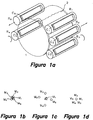
Figure 1a is a schematic perspective depiction of part of a flexographic machine with five printing rollers, in which some of the most relevant elements to be taken in account by the method proposed by the present invention for one embodiment can be seen, -
Figure 1b is a schematic plan view of a series of marks printed in step i) of the method proposed by the second aspect of the invention, using the machine ofFigure 1a , -
Figure 1c is a schematic plan view of a series of marks printed in step iv) of the method proposed by the second aspect of the invention, using the machine ofFigure 1a , for the same embodiment ofFigure 1b , -
Figure 2a is a schematic perspective depiction of part of a flexographic machine with seven printing rollers, in which some of the most relevant elements to be taken into account by the method proposed by the present invention for another embodiment can be seen, -
Figure 2b is a schematic plan view of a series of marks printed in step i) of the method proposed by the second aspect of the invention using the machine ofFigure 2a , -
Figure 2c is a schematic plan view of a series of marks printed in step iv) of the method proposed by the second aspect of the invention using the machine ofFigure 2a for the same embodiment ofFigure 2b , - Figure 3a is a schematic perspective depiction of part of a flexographic machine with five printing rollers, in which some of the most relevant elements to be taken into account by the method proposed by the second aspect of the present invention for one embodiment can be seen,
- Figure 3b is a schematic plan view of a series of marks as they would appear printed using the machine of Figure 3a for one embodiment for which all the marks would appear superposed,
- Figure 3c is a schematic plan view of a series of marks printed in step ii) of the method proposed using the machine of Figure 3a for the same embodiment of Figure 3b, and
- Figure 3d is another schematic plan view of a series of printed superposed marks after having performed a register adjustment of the printing rollers of the machine of Figure 3a according to the method proposed by the invention for the same embodiment of Figures 3b and 3c.
- The present invention relates to a method of determining printed images, of the type comprising the use of a printer of any type but with at least two printing groups with respective printing rollers with respective characteristic images to be printed.
- The explanation of the proposed method applied to a printing machine with two printing rollers has already been provided in the section of the explanation of the invention, the proposed method being described in this section for several embodiments based on the use of a printing machine (specifically a flexographic machine but it could be another machine which a person skilled in the art would consider suitable) with a plurality of printing rollers: five for the embodiment shown in
Figures 1a to 1c and 3a to 3d, and seven for the embodiment ofFigures 2a to 2c . - Although the method is applicable for any type of characteristic image, of any size and location, for the embodiments shown in the
Figures 1a to 1c and 2a to 2c referring to the second aspect of the invention, said characteristic images are auxiliary marks for register M1, M2, M3...Mn located in respective sides of printing plates C1, C2, C3...Cn, for being printed in a side margin of alaminar material 2 to be printed. - The preceding paragraph refers to the marks and to the printing plates, and reference will also later be made to the rollers, indicating the maximum number as n, due to the fact that said number n may vary depending on the embodiment, specifically for the embodiment shown in
Figures 1a to 1c and 3a to 3d n=5, and for the embodiment shown inFigures 2a to 2c n=7. - As can be seen in
Figures 1a ,2a and 3a, for several embodiments, the method is applied to a flexographic printer of the type comprising a rotating support drum 1 (shown transparently for the sake of visual clarity) on which a laminar material to be printed 2 (shown only in part for the sake of clarity) is supported, with a plurality of printing groups (not all shown) arranged around saidsupport drum 1 and spaced along its perimeter, including respective printing rollers R1, R2, R3... Rn, each of them with at least one respective mark to be printed M1, M2, M3...Mn. - For said embodiments shown, the method comprises performing all the steps for all the printing groups and all the marks M1, M2, M3...Mn.
-
Figures 1b and2b show the marks printed by the first printing of step i) of the method proposed by the second aspect of the invention (said figures do not show thelaminar material 2 on the they have been printed). - It can be seen both in
Figure 1b and in the 1c, and, though not as well, inFigure 1a , how the marks M1, M2, M3, M4, M5 therein shown are respective circles which, although it cannot be seen since the drawings are in black and white, have each been printed with a different color, the mentioned color of each mark M1, M2, M3, M4, M5 for one embodiment being the characteristic which allows distinguishing them from one another. - For another embodiment, the mentioned distinguishing characteristic of the marks is the relative position within the printing, there being for said embodiment a series of windows (one per mark) delimiting respective areas where it is possible to detect a mark, each mark being moved, according to the proposed method, only through the inside of its respective window, without the possibility of entering in the window of another mark. In other words, even though the marks, for example the marks shown in
Figures 1b and 1c M1, M2, M3, M4, M5, are of the same color, the fact that each of them can be moved only through the inside of its respective window (not shown) allows distinguishing them by their relative position, despite the fact that all of them are identical and the same color. - In said
Figure 1b , the marks M1, M2, M3, M4, M5 have been printed longitudinally separated along the mentioned margin of thelaminar material 2, and they also appear out of both transverse and longitudinal register. - In relation to marks M1, M2, M3, M4, M5, M6, M7 shown in
Figures 2a to 2c , these marks are respective segments of lines, each of them with a different inclination, and which unlike the marks ofFigures 1a to 1c , have been printed substantially on one and the same marginal area of thelaminar material 2, without being longitudinally separated along thelaminar material 2 by more than the small (longitudinal and transverse) separations typical of register errors (which can be seen inFigure 2b ), or the separations forced in step iii) of the proposed method which can be seen inFigure 2c (as also occurs with the embodiment ofFigure 1c ). - For another embodiment not shown, the marks M1, M2, M3...Mn are different geometric figures.
- It can be seen in
Figures 1a ,2a and 3a how for the embodiments therein shown the marks M1, M2, M3...Mn are defined or incorporated in respective printing plates C1, C2, C3...Cn, said printing rollers R1, R2, R3... Rn being associated to said characteristic images M1, M2, M3...Mn since each of them carries one of said printing plates C1, C2, C3...,Cn. - The method proposed by the second aspect of the invention comprises performing previously described step ii) for detecting the marks as they are depicted in
Figures 1b and2b . - Said detections of said step ii), and of step v) described in further detail below, are performed by means of an automatic detection system which, for the embodiment shown in
Figures 2b and 2c , comprises, for the purpose of performing the detections visually, an automatic image capture and treatment system (not shown) formed, for example, by at least one camera located above therotating support drum 1, upstream with respect to the direction of movement of thelaminar material 2, associated to a corresponding electronic circuitry, directly on the printedlaminar material 2 or in a corresponding monitor or display (not shown), said automatic image capture and treatment system being associated to a corresponding electronic system suitable for performing at least said steps vi) to ix), as well as collaborating, if necessary, when performing steps ii) and v), as well as giving the orders by means of the corresponding sending of suitable control signals to means of actuating the groups and the printing rollers, which allow performing steps i), iii) and iv). - For one embodiment for which it is not necessary to detect the shape or the color of the marks, and for which it is therefore not necessary to use a camera, such as that mentioned above for which the marks were distinguished from one another by their relative position within the printing, the mentioned automatic detection system comprises one or more photoelectric sensors, also associated to an electronic system like that described in the preceding paragraph.
- In relation to step iii) of the method proposed by the second aspect of the invention, said step comprises moving the transverse and/or longitudinal register of at least all except one of said printing rollers R1, R2, R3... Rn, each in a different direction or in the same direction as another but with a different magnitude different, or withdrawing same from printing status.
- Specifically for the embodiment of
Figure 1a , step iii) is performed for moving the printing rollers R1, R2, R3, R4, R5 shown therein according to the indicative arrows also shown therein, i.e.: - moving the longitudinal, or angular, register of a first printing roller R1 in one direction, and of a second printing roller R2 in the opposite direction, and
- moving the transverse, or axial, register of a fourth R4 and a fifth R5 printing rollers, each in one direction.
- With respect to the third printing roller R3, the latter is not actuated in said step iii), therefore it does not move in any direction.
- The result of said movements, or the absence thereof as is the case of the third printing roller R3, can be seen in
Figure 1c , and is detectable in step v) of the proposed method. - Said
Figure 1c shows the previous positions of the marks (i.e., those shown inFigure 1a ) by means of a number of corresponding "x", which allows performing a comparison with their respective current positions, which allows appreciating how all the marks, except that indicated as M3, have undergone respective positional discrepancies, determined in step vi) of the method, and different from one another, specifically mark M5 has been moved to the right mark M4 to the left, mark M2 upwards and mark M1 downwards. In other words, said step vi) has been performed to determine a series of positional discrepancies different for all except one of the marks, i.e., for M1, M2, M4 and M5. - Continuing with the embodiment of
Figures 1a to 1c , the method proposed by the second aspect of the invention comprises performing said step vii.1) to determine that each of the printing rollers R1, R2, R4 and R5 actuated in step iii) is associated to one of said marks M1, M2, M4 and M5 which have undergone respective positional discrepancies, if the transverse and/or longitudinal register of said printing roller R1, R2, R4 and R5 has been moved in said step iii), with a direction corresponding to that experienced by the printed mark M2, M3, M4 and M5, i.e., mark M2 corresponds to roller R2, M3 to R3, M4 to R4 and M5 to R5. - The method comprises determining in step vii.2) that the third roller R3, the register of which has not been moved, is associated to mark M3 which has not undergone any positional discrepancy.
- The movements to which the registers of the printing rollers have been subjected in step iii) are enough for the embodiment shown in
Figures 1a to 1c , but this is not the case for one embodiment which involves using a machine with a larger number of printing rollers, as is the case shown inFigure 2a . - For the embodiment of
Figure 2a , step iii) is performed for moving the printing rollers R1, R2, R3, R4, R5, R6, R7, shown therein according to the indicative arrows also shown therein, i.e.: - withdrawing from printing status a first printing roller R1,
- moving the longitudinal register of a second printing roller R2 in one direction, and that of a third printing roller R3 in the opposite direction, and
- moving the transverse register of a sixth printing roller R6 in one direction, and that of a fifth R5 and a seventh R7 printing rollers in one and the same direction, opposite to that of roller R6, but with a different magnitude, specifically with a magnitude greater than roller R5 as is sought to be indicated with the longer length of the arrow therein shown.
- Obviously the fact that a certain roller of is moved in one way or another, for example the sixth roller R6 axially in one direction, must only be interpreted as an example for explaining the rollers shown in
Figures 1a and2a , since the number of the roller which undergoes a certain movement is irrelevant, it can be the first or the second, etc., what is important is that said movements are different from one another (either relating to the type of movement, to the direction, to, if necessary, the magnitude of the movement or to a combination thereof). - Continuing with the embodiment shown in
Figures 2a to 2c , the fourth printing roller R4 is not actuated in said step iii), therefore it is not moved in any direction. - The result of said movements, or the absence thereof as in the case of the fourth printing roller R4, can be seen in
Figure 2c , and is detectable in step v) of the proposed method. - Said
Figure 2c also shows how all the marks, except those indicated as M4 and as M1, have undergone respective positional discrepancies, determined in step vi) of the method, and different from one another, specifically mark M5 has been moved to the right, mark M6 to the left, mark M3 upwards, mark M2 downwards and mark M7 also to the right but with a smaller magnitude than M5. In other words, said step vi) has been performed to determine a series of positional discrepancies different for all except two of the marks, i.e., for M2, M3, M5, M6 and M7. -
Figure 2c also shows that mark M1 has not been printed, which has been determined in step vi) as a disappearance of said mark M1. - Continuing with the embodiment of
Figures 2a to 2c , the method proposed by the second aspect of the invention comprises performing said step vii.1) to determine that each of the printing rollers R2, R3, R5, R6 and R7 actuated in step iii) is associated to one of said marks M2, M3, M5, M6 and M7 which have undergone respective positional discrepancies, if the transverse and/or longitudinal register of said printing roller R2, R3 R5, R6 and R7 has been moved in said step iii), with a direction and a magnitude corresponding to that experienced by the printed mark M2, M3, M5, M6 and M7, i.e., mark M2 corresponds to roller R2, M3 to R3, M5 to R5, M6 to R6, and M7 to R7. - For one embodiment said magnitudes have pre-determined values.
- Continuing with the embodiment of
Figures 2a to 2c , the method proposed by the second aspect of the invention comprises determining in step vii.2) that the fourth roller R4, which has not been moved, is associated to the mark M4 which has not undergone any positional discrepancy, as well as performing said step vii.3) to determine that the first printing roller R1 withdrawn from the printing upon being actuated in said step iii) is associated to the first mark M1, which has disappeared from the printing. - For one embodiment the proposed method is performed before a process of register adjustment of said printing rollers R1, R2, R3... Rn.
- For another embodiment the method proposed by the second aspect of the invention is performed before a process of pressure adjustment of at least part of the rollers of said printing groups.
- In relation to the method proposed by the first aspect of the invention, it can be observed in Figures 3b to 3d (as well as, although with more difficulty in Figure 3a in its respective printing plates C1, C2, C3, C4, C5), how the marks M1, M2, M3, M4, M5 shown therein are respective circles (Figures 3b to 3d do not show the
laminar material 2 on which the marks have been printed), in this case partially superposed and printed within a determined area Z (shown with a dashed line). Unlike Figures 3b and 3d, Figure 3b shows a hypothetical preliminary printing, for the purpose of clarifying the explanation of the method proposed by the first aspect of the invention, since it is not essential to perform printing of the marks M1, M2, M3, M4, M5 before step a). - Said circles are an exaggerated representation of the real marks, for the sake of clarity, since they are actually microdots generally having a diameter of substantially 0.1 mm to 1 mm or slightly greater.
- For a preferred embodiment said marks M1, M2, M3, M4, M5 are auxiliary mounting marks used for positioning and coupling said printing plates C1, C2, C3, C4 ,C5 on said printing rollers R1, R2, R3, R4, R5.
- Figure 3b shows the marks M1, M2, M3, M4, M5 as they would appear printed if a printing before step a) of the method proposed by the first aspect of the invention, for the embodiment in which they are the mentioned microdots, were performed. It can be seen in said Figure 3b that the microdots M1, M2, M3, M4, M5 appear partially superposed, a register adjustment of the printing rollers R1, R2, R3, R4, R5 not having been yet performed. Said superposition, although partial, initially prevents the determination or discernment of each mark, it not being possible to clearly distinguish each mark separately, which makes it difficult, and even in some cases impossible, to determine which roller each mark belongs to, as well as their pressure adjustment, since the marks are not seen in their entirety, and their register adjustment, since it is not possible to identify which roller each mark belongs to.
- In addition, Figure 3c shows the same marks or microdots M1, M2, M3, M4, M5 once they have been printed, the printing rollers R2, R3, R4, R5 shown in Figure 3a having been moved, for the embodiment shown, according to the indicative arrows also shown therein, i.e.:
- axially moving the transverse register to a second printing roller R2 in one direction, and to a fifth printing roller R5 in the opposite direction, and
- angularly moving the longitudinal register of a third R3 and a fourth R4 printing rollers, each in one direction.
- In relation to the first printing roller R1, it is not actuated, therefore it is not moved in any direction.
- The result of said movements, or the absence thereof as is the case of the first printing roller R1, can be seen in Figure 3c, and can be detected.
- Said Figure 3c depicts the preliminary positions that the marks would have adopted if they had been printed (i.e., those shown in Figure 3a) by means of corresponding "x", which allows performing a comparison with their respective current positions, which allows appreciating how all the marks, except that indicated as M1, have undergone respective positional discrepancies.
- Actually, it is not necessary to perform printing before moving the printing roller register, i.e., the printing shown by Figure 3b is not performed, therefore the mentioned positional discrepancies are not determined by comparing each printed mark with its preliminary position but rather by means of comparing the relative positions detected with the relative position of said area Z of the
material 2, to determine the positional discrepancies for all the marks M2, M3, M4, M5 except for a first mark indicated as M1. - It can be seen in said Figure 3c, where the marks M1, M2, M3, M4 and M5 appear printed not superposed in relation to another, how the positional discrepancies with respect to the area Z, are different from one another, specifically the mark M5 has moved to the right of said area Z, the mark M4 downwards, the mark M2 towards the left and the mark M3 upwards. In other words, said step has been performed to determine a series of different positional discrepancies for all except one of the marks, i.e., for M2, M3, M4 and M5.
- Once the marks M1, M2, M3, M4 and M5 have been separated as seen in Figure 3c, they can be easily distinguished, which makes it possible to perform the operations of determining or associating marks M1, M2, M3, M4 and M5 with respect to printing rollers R1, R2, R3, R4, R5 as well as register adjustment and pressure adjustment of the printing rollers R1, R2, R3, R4, R5.
- The embodiments described for the second aspect of the invention for which there was a larger number of printing rollers than those shown by Figure 3a and, as a result, identical movements with one and the same direction for two different printing rollers, but with different pre-determined magnitudes, are also applicable in a similar manner, with the difference that steps i) and ii) of the method proposed are not necessary according to the first aspect, whereby the comparisons to determine the positional discrepancies are performed with respect to the area Z shown in Figures 3b to 3c.
- The method proposed comprises performing said pressure adjustment by means of using an automatic image capture (camera or the like) and treatment system associated to an electronic system for, according to one embodiment, detecting the absence or presence of each of said marks M1, M2, M3, M4, M5 on said
laminar material 2 and acting accordingly by increasing or decreasing the pressure exerted by each printing roller R1, R2, R3, R4, R5 on thelaminar material 2, as well as the pressure of their associated ink rollers (not shown). - For a more elaborate embodiment the method proposed by the invention comprises, to perform said pressure adjustment, comparing, by means of said electronic system, the marks M1, M2, M3, M4, M5 captured with respective pre-determined reference marks registered in said electronic system and indicative of a good printing quality (due to their color, shape, etc.), and if said comparison offers as a result a discrepancy or deviation indicative of the fact that the quality of any of the marks M1, M2, M3, M4, M5 captured is not good, compensating said discrepancy by means of adjusting the pressure of the corresponding printing roller R1, R2, R3, R4, R5 which has printed said image and of a corresponding ink roller (not shown) to which it is associated.
- In relation to the mentioned register adjustment, for a preferred embodiment the method proposed comprises taking as a common reference a first mark M1, the printing roller R1 of which has not been moved , and adjusting the position of the printing rollers R2, R3, R4, R5 carrying the remaining marks M2, M3, M4, M5 until the position of said marks M2, M3, M4, M5, once they have been printed on the
material 2, is identical to that of said first mark M1, i.e., until all the marks M1, M2, M3, M4, M5 overlap as shown in Figure 3d. To that end, the method proposed comprises: - comparing the relative positions detected for each of the printed marks M2, M3, M4, M5, except for said first M1, with respective relative register positions equal to the position of the first mark M1 detected, or common reference register position, plus the known movement (actuation of the axial or angular roller) of the transverse and/or longitudinal register undergone by each of the marks M2, M3, M4, M5 in said step a),
- adjusting the transverse and longitudinal register of the printing rollers R2, R3, R4, R5 the marks M2, M3, M4, M5 of which have been printed with a relative position different from the relative register position with which it has been compared, until each of them has reached its respective relative register position, and
- moving each of the printing rollers R2, R3, R4, R5 according to the same movement undergone in said step of moving the printer rollers, identical in magnitude and along the same movement axis, but in an opposite direction, so that all the marks M1, M2, M3, M4, M5 are printed completely superposed in relation to one another on the
laminar material 2 in said common reference register position or position of the first mark M1 within said area Z, as shown in Figure 3d. - For another non-preferred embodiment the common reference position is not the position of the first mark M1 detected, but another different one, such as a pre-determined position different from the relative positions of the marks M1, M2, M3, M4, M5 detected , it being possible for said embodiment, not shown, that the first mark M1 has also been moved in initial step, since it is not used as reference for the register adjustment of the printing rollers R2, R3, R4, R5 of the remaining marks M2, M3, M4, M5.
- Continuing with the embodiment shown, it can be observed in Figure 3d how once all the marks M1, M2, M3, M4, M5, particularly mounting microdots, are located in the common reference register position, they are completely superposed, it not being possible to distinguish in said Figure 3d more than a single circle, representative of all the completely superposed microdots M1, M2, M3, M4, M5.
- A person skilled in the art could introduce changes and modifications in the described embodiments without departing from the scope of the present improvements as it is defined in the attached claims.
Claims (15)
- A method for determining printed images with respect to printing groups, comprising the use of a printer with at least one first and one second printing groups including respective first (R1) and second (R2) printing rollers having one and the same printing development, each of said printing rollers (R1, R2) with at least one respective characteristic image (M1; M2) to be printed on a laminar material (2), said characteristic images (M1; M2) being auxiliary marks and said method comprising:i) actuating at least said printing groups to perform a first printing of said characteristic images (M1, M2) on said laminar material (2) to be printed;and said method being characterized in that it comprises determining which roller is associated to each of said characteristic images (M1, M2) by means of the automatic and sequential performance, after said step i), of the following steps:ii) detecting, by means of an automatic detection system, said characteristic images (M1, M2) once they have been printed on the material to be printed (2), to at least identify them and know their relative position within said printing development,iii) moving in a controlled manner the transverse and/or longitudinal register of at least one of said printing rollers (R2),iv) actuating at least said printing groups to perform a second printing of said characteristic images (M1, M2) on said laminar material (2) to be printed;v) detecting on the material to be printed (2), by means of said automatic detection system, said characteristic images (M1, M2) printed on the material to be printed (2), to at least identify them and know their relative position within said printing development,vi) comparing the result of the detections of step v) with that of the detections of step ii) to determine a possible positional discrepancy for at least one of the characteristic images (M1, M2),vii.1) determining that one of said printing rollers (R1, R2) is associated to a characteristic image (M1, M2) which has undergone a positional discrepancy, which is at least one in number, at least if the transverse and/or longitudinal register of said printing roller (R1, R2) has been moved in said step iii),
and/orvii.2) determining that one of said printing rollers (R1, R2) is associated to one of said characteristic images (M1, M2), which has not undergone a positional discrepancy, if the register of said printing roller (R1, R2) has not been moved in said step iii). - The method according to claim 1, characterized in that said step vii.1) comprises determining that one of said printing rollers (R1, R2) is associated to said characteristic image (M1, M2) which has undergone a positional discrepancy, which is at least one in number, if the register of said printing roller (R1, R2) has been moved in said step iii), at least with a direction corresponding to that experienced by the printed characteristic image (M1, M2) which has undergone said positional discrepancy.
- The method according to claim 1, characterized in that the steps of claims 1 are performed before a process of pressure and/or register adjustment of at least part of the printing rollers (R1, R2).
- The method according to claim 1, 2 or 3, characterized in that it comprises performing at least said steps vi) to ix) by means of an electronic system associated to said automatic detection system.
- The method according to claim 1, 2, 3 or 4, characterized in that said detections performed on steps ii) and v) are performed by means of an automatic detection system which comprises an automatic image capture and treatment system including one or more photoelectric sensors or at least one camera.
- The method according to claim 5, characterized in that steps i), iii) and iv) are performed by an electronic system sending orders by means of suitable control signals to means of actuating the groups and the printing rollers.
- The method according to claim 6, characterized in that steps ii) and v) are performed with the collaboration of said electronic system being associated to said automatic image capture and treatment system.
- The method according to claim 4, 5, 6 or 7, characterized in that to perform said pressure adjustment it comprises comparing, by means of said electronic system, the characteristic images (M1, M2, M3...Mn) captured with respective pre-determined reference characteristic images registered in said electronic system and indicative of a good printing quality, and if said comparison offers as a result a discrepancy or deviation indicative of the fact that the quality of any of the characteristic images (M1, M2, M3...Mn) captured is not sufficient, compensating said discrepancy by means of adjusting the pressure of the corresponding printing roller (R1, R2, R3... Rn) which has printed said image and of a corresponding ink roller to which it is associated.
- A method for determining printed images with respect to printing groups, comprising the use of a printer with at least one first and one second printing groups including respective first (R1) and second (R2) printing rollers having one and the same printing development, each of said printing rollers (R1, R2) with at least one respective characteristic image (M1, M2) to be printed on a laminar material (2), said characteristic images (M1, M2) being auxiliary marks and said method comprising:i) actuating at least said printing groups to perform a first printing of said characteristic images (M1, M2) on said laminar material (2) to be printed;and said method being characterized in that it comprises determining which roller is associated to each of said characteristic images (M1, M2) by means of the automatic and sequential performance, after said step i), of the following steps:ii) detecting, by means of an automatic detection system, said characteristic images (M1, M2) once they have been printed on the material to be printed (2), to at least identify them and know their relative position within said printing development,iii) withdrawn the printing status from at least one of said printing rollers (R2),iv) actuating at least said printing groups to perform a second printing of said characteristic images (M1, M2) on said laminar material (2) to be printed;v) detecting on the material to be printed (2), by means of said automatic detection system, said characteristic images (M1, M2) if they have been printed again on the material to be printed (2), to at least identify them and know their relative position within said printing development, and detect the absence of the characteristic images (M1, M2) which have not been printed again on said laminar material (2) in said step iv),vi) comparing the result of the detections of step v) with that of the detections of step ii) to determine the disappearance of one of said characteristic images (M1, M2),vii.3) determining that one of said printing rollers (R1, R2) is associated to one of said characteristic images (M1, M2), which has disappeared from the printing, if said printing roller (R1, R2) has been withdrawn from the printing status in said step iii).
- The method according to claim 9, characterized in that after performing step vii.3), at least one operation of pressure adjustment of said printing rollers (R1, R2) is performed.
- The method according to claim 9 or 10, characterized in that it comprises performing at least said steps vi) to ix) by means of an electronic system associated to said automatic detection system.
- The method according to claim 9, 10 or 11, characterized in that said detections performed on steps ii) and v) are performed by means of an automatic detection system which comprises an automatic image capture and treatment system including one or more photoelectric sensors or at least one camera.
- The method according to claim 12, characterized in that steps i), iii) and iv) are performed by an electronic system sending orders by means of suitable control signals to means of actuating the groups and the printing rollers.
- The method according to claim 13, characterized in that steps ii) and v) are performed with the collaboration of said electronic system being associated to said automatic image capture and treatment system.
- The method according to claim 11, 12, 13 or 14, characterized in that to perform said pressure adjustment it comprises comparing, by means of said electronic system, the characteristic images (M1, M2, M3...Mn) captured with respective pre-determined reference characteristic images registered in said electronic system and indicative of a good printing quality, and if said comparison offers as a result a discrepancy or deviation indicative of the fact that the quality of any of the characteristic images (M1, M2, M3...Mn) captured is not sufficient, compensating said discrepancy by means of adjusting the pressure of the corresponding printing roller (R1, R2, R3... Rn) which has printed said image and of a corresponding ink roller to which it is associated.
Applications Claiming Priority (2)
| Application Number | Priority Date | Filing Date | Title |
|---|---|---|---|
| ES200602036A ES2300196B1 (en) | 2006-07-28 | 2006-07-28 | METHOD OF DETERMINATION OF PRINTED IMAGES REGARDING PRINTING GROUPS. |
| PCT/ES2007/000348 WO2008012381A2 (en) | 2006-07-28 | 2007-06-12 | Method for determining printed images |
Publications (3)
| Publication Number | Publication Date |
|---|---|
| EP2055482A2 EP2055482A2 (en) | 2009-05-06 |
| EP2055482A4 EP2055482A4 (en) | 2010-04-14 |
| EP2055482B1 true EP2055482B1 (en) | 2018-11-14 |
Family
ID=38981825
Family Applications (1)
| Application Number | Title | Priority Date | Filing Date |
|---|---|---|---|
| EP07788596.0A Active EP2055482B1 (en) | 2006-07-28 | 2007-06-12 | Method for determining printed images |
Country Status (4)
| Country | Link |
|---|---|
| EP (1) | EP2055482B1 (en) |
| BR (1) | BRPI0714647B1 (en) |
| ES (2) | ES2300196B1 (en) |
| WO (1) | WO2008012381A2 (en) |
Families Citing this family (6)
| Publication number | Priority date | Publication date | Assignee | Title |
|---|---|---|---|---|
| EP2384889A1 (en) * | 2010-05-03 | 2011-11-09 | Advanced Vision Technology (AVT) Ltd. | Method for adjusting and controlling a printing machine by employing minute marks |
| ITVI20100163A1 (en) * | 2010-06-11 | 2011-12-12 | Ofem Converting S R L | PROCEDURE FOR ALIGNMENT OF COLOR REGISTERS FOR PRINTING MACHINES AND ITS PROGRAM FOR PROCESSING |
| EP2422979A1 (en) * | 2010-08-31 | 2012-02-29 | Fischer & Krecke GmbH | Rotary printing press with central impression cylinder |
| ES2395182B1 (en) * | 2011-08-12 | 2013-11-28 | Comexi Group Industries, Sau | METHOD FOR CONTROLLING THE OPERATION OF A PRINTER MACHINE AND FLEXOGRAPHIC PRINTER MACHINE FOR IMPLEMENTATION. |
| EP3251849A1 (en) * | 2016-05-31 | 2017-12-06 | Windmöller & Hölscher KG | Flexographic printing machine |
| EP4026697A1 (en) * | 2021-01-08 | 2022-07-13 | manroland Goss web systems GmbH | Print control strip |
Family Cites Families (8)
| Publication number | Priority date | Publication date | Assignee | Title |
|---|---|---|---|---|
| DE3136701C1 (en) * | 1981-09-16 | 1983-04-07 | M.A.N.- Roland Druckmaschinen AG, 6050 Offenbach | Device for scanning registration marks which are printed on printed matter and characterize the positional accuracy of the printing ink application |
| FR2578486B1 (en) * | 1985-03-08 | 1987-06-12 | Bertin & Cie | METHOD AND DEVICE FOR POSITIONING OBJECTS IN RELATION TO OTHERS, IN PARTICULAR COLOR PRINTING ROLLERS IN A ROTARY OFFSET PRESS |
| US4887530A (en) * | 1986-04-07 | 1989-12-19 | Quad/Tech, Inc. | Web registration control system |
| DE3809941A1 (en) * | 1987-03-26 | 1988-10-06 | Koenig & Bauer Ag | METHOD FOR POSITIONING PLATE CYLINDERS IN A MULTI-COLOR ROTARY PRINTING MACHINE |
| DE19614397C2 (en) * | 1996-04-12 | 2001-04-26 | Roland Man Druckmasch | Drive with register device for a printing unit of a web-fed rotary printing press |
| NL1004663C2 (en) * | 1996-12-02 | 1998-06-03 | Q I Press Controls V O F | Method and device for checking printed matter. |
| US5857784A (en) * | 1997-01-28 | 1999-01-12 | Bayer Corp. Agfa Division | Image position error detection technique |
| DE60320858D1 (en) * | 2003-03-20 | 2008-06-19 | Comexi Sa | METHOD FOR REGISTERING DIFFERENT COLORS IN FLEXOGRAPHY AND FLEXOGRAPHIC PRINTERS INCLUDING A DEVICE FOR IMPLEMENTING THE PROCESS |
-
2006
- 2006-07-28 ES ES200602036A patent/ES2300196B1/en active Active
-
2007
- 2007-06-12 ES ES07788596T patent/ES2712248T3/en active Active
- 2007-06-12 EP EP07788596.0A patent/EP2055482B1/en active Active
- 2007-06-12 BR BRPI0714647-7A patent/BRPI0714647B1/en active IP Right Grant
- 2007-06-12 WO PCT/ES2007/000348 patent/WO2008012381A2/en active Application Filing
Non-Patent Citations (1)
| Title |
|---|
| None * |
Also Published As
| Publication number | Publication date |
|---|---|
| EP2055482A4 (en) | 2010-04-14 |
| ES2712248T3 (en) | 2019-05-10 |
| WO2008012381B1 (en) | 2008-04-17 |
| WO2008012381A2 (en) | 2008-01-31 |
| BRPI0714647A2 (en) | 2012-12-25 |
| BRPI0714647B1 (en) | 2018-07-31 |
| EP2055482A2 (en) | 2009-05-06 |
| WO2008012381A3 (en) | 2008-03-06 |
| ES2300196B1 (en) | 2009-02-01 |
| ES2300196A1 (en) | 2008-06-01 |
Similar Documents
| Publication | Publication Date | Title |
|---|---|---|
| US7664294B2 (en) | System for automatic quality inspection of a printed image, comprising an image sensor, evaluation unit and display | |
| EP2055482B1 (en) | Method for determining printed images | |
| JP4294613B2 (en) | Method and apparatus for initial adjustment of engraving cylinder alignment of rotary multicolor press | |
| US5806430A (en) | Digital printing press with register adjustment and method for correcting register errors therein | |
| US6129015A (en) | Method and apparatus for registering color in a printing press | |
| US9855738B2 (en) | Method for controlling the operation of a printing press and a flexographic printing press for implementing said method | |
| US8813647B2 (en) | Method and device for determining register deviations through recursion analysis | |
| US6553908B1 (en) | Web fanout control system | |
| EP2085223B1 (en) | Method for positional adjustment of printer bodies in flexographic printing machines | |
| EP1897690B1 (en) | Method of automatically adjusting the printing pressure in flexographic printers | |
| EP2384889A1 (en) | Method for adjusting and controlling a printing machine by employing minute marks | |
| US7219606B2 (en) | Method and apparatus for measuring, setting and controlling longitudinal and lateral register as well as parallelness of the printing register in a multicolor printing machine | |
| EP1604820B1 (en) | Method of registering different colours in flexography, and flexographic printer comprising a device for implementing said method | |
| WO2004098890A1 (en) | Polychrome rotary press | |
| US20040103810A1 (en) | Method of compensating for misregistration during operation of a printing press | |
| US6848361B2 (en) | Control device and method to prevent register errors | |
| JP2002137529A (en) | Method for suppressing overfilling or underfilling in production of printing original image to minimum | |
| US20080072776A1 (en) | Home positon storage unit and home position storage method for use with printing press | |
| JP2003089194A (en) | Apparatus for mounting and confirming machine plate of printer and printer using the same | |
| US6522857B2 (en) | Method and apparatus for setting registration in a multicolor printing machine based on printing substrates | |
| DE102004036876A1 (en) | Method for the pre-setting register locating unit of plate cylinder for sheet-fed offset printing press involves positioning of register mark through register mark measuring system with stationary sensors | |
| EP1482383A1 (en) | Method and control device for avoiding of registration errors | |
| DE102006050743A1 (en) | Inline sensor's e.g. spectral, densitometric measuring sensor, measuring clock pulse preadjusting method for e.g. sheet-feed offset rotary printing machine, involves finding rotational angle for measuring clock pulse from strips position | |
| JP2836930B2 (en) | Register adjustment method and device | |
| TWI590955B (en) | Set version control method and device |
Legal Events
| Date | Code | Title | Description |
|---|---|---|---|
| PUAI | Public reference made under article 153(3) epc to a published international application that has entered the european phase |
Free format text: ORIGINAL CODE: 0009012 |
|
| 17P | Request for examination filed |
Effective date: 20090216 |
|
| AK | Designated contracting states |
Kind code of ref document: A2 Designated state(s): AT BE BG CH CY CZ DE DK EE ES FI FR GB GR HU IE IS IT LI LT LU LV MC MT NL PL PT RO SE SI SK TR |
|
| AX | Request for extension of the european patent |
Extension state: AL BA HR MK RS |
|
| DAX | Request for extension of the european patent (deleted) | ||
| RAP1 | Party data changed (applicant data changed or rights of an application transferred) |
Owner name: COMEXI GROUP INDUSTRIES, S.A. |
|
| A4 | Supplementary search report drawn up and despatched |
Effective date: 20100317 |
|
| RIC1 | Information provided on ipc code assigned before grant |
Ipc: B41F 33/00 20060101AFI20090309BHEP Ipc: B41F 13/14 20060101ALI20100311BHEP |
|
| 17Q | First examination report despatched |
Effective date: 20160627 |
|
| STAA | Information on the status of an ep patent application or granted ep patent |
Free format text: STATUS: EXAMINATION IS IN PROGRESS |
|
| GRAP | Despatch of communication of intention to grant a patent |
Free format text: ORIGINAL CODE: EPIDOSNIGR1 |
|
| STAA | Information on the status of an ep patent application or granted ep patent |
Free format text: STATUS: GRANT OF PATENT IS INTENDED |
|
| INTG | Intention to grant announced |
Effective date: 20180705 |
|
| GRAS | Grant fee paid |
Free format text: ORIGINAL CODE: EPIDOSNIGR3 |
|
| GRAA | (expected) grant |
Free format text: ORIGINAL CODE: 0009210 |
|
| STAA | Information on the status of an ep patent application or granted ep patent |
Free format text: STATUS: THE PATENT HAS BEEN GRANTED |
|
| AK | Designated contracting states |
Kind code of ref document: B1 Designated state(s): AT BE BG CH CY CZ DE DK EE ES FI FR GB GR HU IE IS IT LI LT LU LV MC MT NL PL PT RO SE SI SK TR |
|
| REG | Reference to a national code |
Ref country code: GB Ref legal event code: FG4D |
|
| REG | Reference to a national code |
Ref country code: CH Ref legal event code: EP Ref country code: AT Ref legal event code: REF Ref document number: 1064329 Country of ref document: AT Kind code of ref document: T Effective date: 20181115 |
|
| REG | Reference to a national code |
Ref country code: DE Ref legal event code: R096 Ref document number: 602007056824 Country of ref document: DE |
|
| REG | Reference to a national code |
Ref country code: IE Ref legal event code: FG4D |
|
| REG | Reference to a national code |
Ref country code: NL Ref legal event code: MP Effective date: 20181114 |
|
| REG | Reference to a national code |
Ref country code: LT Ref legal event code: MG4D |
|
| REG | Reference to a national code |
Ref country code: AT Ref legal event code: MK05 Ref document number: 1064329 Country of ref document: AT Kind code of ref document: T Effective date: 20181114 |
|
| PG25 | Lapsed in a contracting state [announced via postgrant information from national office to epo] |
Ref country code: BG Free format text: LAPSE BECAUSE OF FAILURE TO SUBMIT A TRANSLATION OF THE DESCRIPTION OR TO PAY THE FEE WITHIN THE PRESCRIBED TIME-LIMIT Effective date: 20190214 Ref country code: AT Free format text: LAPSE BECAUSE OF FAILURE TO SUBMIT A TRANSLATION OF THE DESCRIPTION OR TO PAY THE FEE WITHIN THE PRESCRIBED TIME-LIMIT Effective date: 20181114 Ref country code: LV Free format text: LAPSE BECAUSE OF FAILURE TO SUBMIT A TRANSLATION OF THE DESCRIPTION OR TO PAY THE FEE WITHIN THE PRESCRIBED TIME-LIMIT Effective date: 20181114 Ref country code: FI Free format text: LAPSE BECAUSE OF FAILURE TO SUBMIT A TRANSLATION OF THE DESCRIPTION OR TO PAY THE FEE WITHIN THE PRESCRIBED TIME-LIMIT Effective date: 20181114 Ref country code: IS Free format text: LAPSE BECAUSE OF FAILURE TO SUBMIT A TRANSLATION OF THE DESCRIPTION OR TO PAY THE FEE WITHIN THE PRESCRIBED TIME-LIMIT Effective date: 20190314 Ref country code: LT Free format text: LAPSE BECAUSE OF FAILURE TO SUBMIT A TRANSLATION OF THE DESCRIPTION OR TO PAY THE FEE WITHIN THE PRESCRIBED TIME-LIMIT Effective date: 20181114 |
|
| REG | Reference to a national code |
Ref country code: ES Ref legal event code: FG2A Ref document number: 2712248 Country of ref document: ES Kind code of ref document: T3 Effective date: 20190510 |
|
| PG25 | Lapsed in a contracting state [announced via postgrant information from national office to epo] |
Ref country code: GR Free format text: LAPSE BECAUSE OF FAILURE TO SUBMIT A TRANSLATION OF THE DESCRIPTION OR TO PAY THE FEE WITHIN THE PRESCRIBED TIME-LIMIT Effective date: 20190215 Ref country code: PT Free format text: LAPSE BECAUSE OF FAILURE TO SUBMIT A TRANSLATION OF THE DESCRIPTION OR TO PAY THE FEE WITHIN THE PRESCRIBED TIME-LIMIT Effective date: 20190314 Ref country code: NL Free format text: LAPSE BECAUSE OF FAILURE TO SUBMIT A TRANSLATION OF THE DESCRIPTION OR TO PAY THE FEE WITHIN THE PRESCRIBED TIME-LIMIT Effective date: 20181114 Ref country code: SE Free format text: LAPSE BECAUSE OF FAILURE TO SUBMIT A TRANSLATION OF THE DESCRIPTION OR TO PAY THE FEE WITHIN THE PRESCRIBED TIME-LIMIT Effective date: 20181114 |
|
| PG25 | Lapsed in a contracting state [announced via postgrant information from national office to epo] |
Ref country code: PL Free format text: LAPSE BECAUSE OF FAILURE TO SUBMIT A TRANSLATION OF THE DESCRIPTION OR TO PAY THE FEE WITHIN THE PRESCRIBED TIME-LIMIT Effective date: 20181114 Ref country code: DK Free format text: LAPSE BECAUSE OF FAILURE TO SUBMIT A TRANSLATION OF THE DESCRIPTION OR TO PAY THE FEE WITHIN THE PRESCRIBED TIME-LIMIT Effective date: 20181114 |
|
| REG | Reference to a national code |
Ref country code: DE Ref legal event code: R097 Ref document number: 602007056824 Country of ref document: DE |
|
| PG25 | Lapsed in a contracting state [announced via postgrant information from national office to epo] |
Ref country code: EE Free format text: LAPSE BECAUSE OF FAILURE TO SUBMIT A TRANSLATION OF THE DESCRIPTION OR TO PAY THE FEE WITHIN THE PRESCRIBED TIME-LIMIT Effective date: 20181114 Ref country code: RO Free format text: LAPSE BECAUSE OF FAILURE TO SUBMIT A TRANSLATION OF THE DESCRIPTION OR TO PAY THE FEE WITHIN THE PRESCRIBED TIME-LIMIT Effective date: 20181114 Ref country code: SK Free format text: LAPSE BECAUSE OF FAILURE TO SUBMIT A TRANSLATION OF THE DESCRIPTION OR TO PAY THE FEE WITHIN THE PRESCRIBED TIME-LIMIT Effective date: 20181114 |
|
| PLBE | No opposition filed within time limit |
Free format text: ORIGINAL CODE: 0009261 |
|
| STAA | Information on the status of an ep patent application or granted ep patent |
Free format text: STATUS: NO OPPOSITION FILED WITHIN TIME LIMIT |
|
| 26N | No opposition filed |
Effective date: 20190815 |
|
| PG25 | Lapsed in a contracting state [announced via postgrant information from national office to epo] |
Ref country code: SI Free format text: LAPSE BECAUSE OF FAILURE TO SUBMIT A TRANSLATION OF THE DESCRIPTION OR TO PAY THE FEE WITHIN THE PRESCRIBED TIME-LIMIT Effective date: 20181114 |
|
| PG25 | Lapsed in a contracting state [announced via postgrant information from national office to epo] |
Ref country code: MC Free format text: LAPSE BECAUSE OF FAILURE TO SUBMIT A TRANSLATION OF THE DESCRIPTION OR TO PAY THE FEE WITHIN THE PRESCRIBED TIME-LIMIT Effective date: 20181114 |
|
| REG | Reference to a national code |
Ref country code: CH Ref legal event code: PL |
|
| GBPC | Gb: european patent ceased through non-payment of renewal fee |
Effective date: 20190612 |
|
| REG | Reference to a national code |
Ref country code: BE Ref legal event code: MM Effective date: 20190630 |
|
| PG25 | Lapsed in a contracting state [announced via postgrant information from national office to epo] |
Ref country code: TR Free format text: LAPSE BECAUSE OF FAILURE TO SUBMIT A TRANSLATION OF THE DESCRIPTION OR TO PAY THE FEE WITHIN THE PRESCRIBED TIME-LIMIT Effective date: 20181114 |
|
| PG25 | Lapsed in a contracting state [announced via postgrant information from national office to epo] |
Ref country code: IE Free format text: LAPSE BECAUSE OF NON-PAYMENT OF DUE FEES Effective date: 20190612 Ref country code: GB Free format text: LAPSE BECAUSE OF NON-PAYMENT OF DUE FEES Effective date: 20190612 |
|
| PG25 | Lapsed in a contracting state [announced via postgrant information from national office to epo] |
Ref country code: BE Free format text: LAPSE BECAUSE OF NON-PAYMENT OF DUE FEES Effective date: 20190630 Ref country code: LU Free format text: LAPSE BECAUSE OF NON-PAYMENT OF DUE FEES Effective date: 20190612 Ref country code: CH Free format text: LAPSE BECAUSE OF NON-PAYMENT OF DUE FEES Effective date: 20190630 Ref country code: LI Free format text: LAPSE BECAUSE OF NON-PAYMENT OF DUE FEES Effective date: 20190630 |
|
| PG25 | Lapsed in a contracting state [announced via postgrant information from national office to epo] |
Ref country code: FR Free format text: LAPSE BECAUSE OF NON-PAYMENT OF DUE FEES Effective date: 20190630 |
|
| PG25 | Lapsed in a contracting state [announced via postgrant information from national office to epo] |
Ref country code: CY Free format text: LAPSE BECAUSE OF FAILURE TO SUBMIT A TRANSLATION OF THE DESCRIPTION OR TO PAY THE FEE WITHIN THE PRESCRIBED TIME-LIMIT Effective date: 20181114 |
|
| PG25 | Lapsed in a contracting state [announced via postgrant information from national office to epo] |
Ref country code: HU Free format text: LAPSE BECAUSE OF FAILURE TO SUBMIT A TRANSLATION OF THE DESCRIPTION OR TO PAY THE FEE WITHIN THE PRESCRIBED TIME-LIMIT; INVALID AB INITIO Effective date: 20070612 Ref country code: MT Free format text: LAPSE BECAUSE OF FAILURE TO SUBMIT A TRANSLATION OF THE DESCRIPTION OR TO PAY THE FEE WITHIN THE PRESCRIBED TIME-LIMIT Effective date: 20181114 |
|
| P01 | Opt-out of the competence of the unified patent court (upc) registered |
Effective date: 20230419 |
|
| PGFP | Annual fee paid to national office [announced via postgrant information from national office to epo] |
Ref country code: DE Payment date: 20230626 Year of fee payment: 17 Ref country code: CZ Payment date: 20230621 Year of fee payment: 17 |
|
| PGFP | Annual fee paid to national office [announced via postgrant information from national office to epo] |
Ref country code: IT Payment date: 20230620 Year of fee payment: 17 Ref country code: ES Payment date: 20230711 Year of fee payment: 17 |