EP2055421A1 - Multi-sheet structures with expanded parts and method for manufacturing same using a blowing agent sandwiched between the sheets - Google Patents
Multi-sheet structures with expanded parts and method for manufacturing same using a blowing agent sandwiched between the sheets Download PDFInfo
- Publication number
- EP2055421A1 EP2055421A1 EP08019131A EP08019131A EP2055421A1 EP 2055421 A1 EP2055421 A1 EP 2055421A1 EP 08019131 A EP08019131 A EP 08019131A EP 08019131 A EP08019131 A EP 08019131A EP 2055421 A1 EP2055421 A1 EP 2055421A1
- Authority
- EP
- European Patent Office
- Prior art keywords
- sheet
- blowing agent
- metal
- selected portion
- aluminum
- Prior art date
- Legal status (The legal status is an assumption and is not a legal conclusion. Google has not performed a legal analysis and makes no representation as to the accuracy of the status listed.)
- Withdrawn
Links
- 239000004604 Blowing Agent Substances 0.000 title claims abstract description 55
- 238000000034 method Methods 0.000 title claims abstract description 27
- 238000004519 manufacturing process Methods 0.000 title description 3
- 238000003466 welding Methods 0.000 claims abstract description 26
- 238000003756 stirring Methods 0.000 claims abstract description 25
- 229910052751 metal Inorganic materials 0.000 claims description 37
- 239000002184 metal Substances 0.000 claims description 37
- 238000010438 heat treatment Methods 0.000 claims description 11
- 229910052782 aluminium Inorganic materials 0.000 claims description 9
- XAGFODPZIPBFFR-UHFFFAOYSA-N aluminium Chemical compound [Al] XAGFODPZIPBFFR-UHFFFAOYSA-N 0.000 claims description 9
- 238000000354 decomposition reaction Methods 0.000 claims description 9
- 239000000843 powder Substances 0.000 claims description 8
- 229910001092 metal group alloy Inorganic materials 0.000 claims description 5
- FYYHWMGAXLPEAU-UHFFFAOYSA-N Magnesium Chemical compound [Mg] FYYHWMGAXLPEAU-UHFFFAOYSA-N 0.000 claims description 4
- 229910012375 magnesium hydride Inorganic materials 0.000 claims description 4
- 239000000463 material Substances 0.000 claims description 4
- -1 titanium hydride Chemical compound 0.000 claims description 4
- 229910000048 titanium hydride Inorganic materials 0.000 claims description 4
- 229910000838 Al alloy Inorganic materials 0.000 claims 4
- 229910045601 alloy Inorganic materials 0.000 claims 4
- 239000000956 alloy Substances 0.000 claims 4
- 238000005304 joining Methods 0.000 description 4
- 230000004048 modification Effects 0.000 description 4
- 238000012986 modification Methods 0.000 description 4
- 230000002028 premature Effects 0.000 description 3
- UFHFLCQGNIYNRP-UHFFFAOYSA-N Hydrogen Chemical compound [H][H] UFHFLCQGNIYNRP-UHFFFAOYSA-N 0.000 description 2
- 238000009792 diffusion process Methods 0.000 description 2
- 239000007789 gas Substances 0.000 description 2
- 238000004026 adhesive bonding Methods 0.000 description 1
- 238000011109 contamination Methods 0.000 description 1
- 238000001816 cooling Methods 0.000 description 1
- 230000001419 dependent effect Effects 0.000 description 1
- 238000010894 electron beam technology Methods 0.000 description 1
- 238000002844 melting Methods 0.000 description 1
- 230000008018 melting Effects 0.000 description 1
- 238000002203 pretreatment Methods 0.000 description 1
Images

Classifications
-
- B—PERFORMING OPERATIONS; TRANSPORTING
- B23—MACHINE TOOLS; METAL-WORKING NOT OTHERWISE PROVIDED FOR
- B23K—SOLDERING OR UNSOLDERING; WELDING; CLADDING OR PLATING BY SOLDERING OR WELDING; CUTTING BY APPLYING HEAT LOCALLY, e.g. FLAME CUTTING; WORKING BY LASER BEAM
- B23K20/00—Non-electric welding by applying impact or other pressure, with or without the application of heat, e.g. cladding or plating
- B23K20/12—Non-electric welding by applying impact or other pressure, with or without the application of heat, e.g. cladding or plating the heat being generated by friction; Friction welding
- B23K20/122—Non-electric welding by applying impact or other pressure, with or without the application of heat, e.g. cladding or plating the heat being generated by friction; Friction welding using a non-consumable tool, e.g. friction stir welding
- B23K20/123—Controlling or monitoring the welding process
-
- B—PERFORMING OPERATIONS; TRANSPORTING
- B21—MECHANICAL METAL-WORKING WITHOUT ESSENTIALLY REMOVING MATERIAL; PUNCHING METAL
- B21D—WORKING OR PROCESSING OF SHEET METAL OR METAL TUBES, RODS OR PROFILES WITHOUT ESSENTIALLY REMOVING MATERIAL; PUNCHING METAL
- B21D26/00—Shaping without cutting otherwise than using rigid devices or tools or yieldable or resilient pads, i.e. applying fluid pressure or magnetic forces
- B21D26/02—Shaping without cutting otherwise than using rigid devices or tools or yieldable or resilient pads, i.e. applying fluid pressure or magnetic forces by applying fluid pressure
- B21D26/06—Shaping without cutting otherwise than using rigid devices or tools or yieldable or resilient pads, i.e. applying fluid pressure or magnetic forces by applying fluid pressure by shock waves
- B21D26/10—Shaping without cutting otherwise than using rigid devices or tools or yieldable or resilient pads, i.e. applying fluid pressure or magnetic forces by applying fluid pressure by shock waves generated by evaporation, e.g. of wire, of liquids
-
- B—PERFORMING OPERATIONS; TRANSPORTING
- B21—MECHANICAL METAL-WORKING WITHOUT ESSENTIALLY REMOVING MATERIAL; PUNCHING METAL
- B21D—WORKING OR PROCESSING OF SHEET METAL OR METAL TUBES, RODS OR PROFILES WITHOUT ESSENTIALLY REMOVING MATERIAL; PUNCHING METAL
- B21D47/00—Making rigid structural elements or units, e.g. honeycomb structures
-
- B—PERFORMING OPERATIONS; TRANSPORTING
- B21—MECHANICAL METAL-WORKING WITHOUT ESSENTIALLY REMOVING MATERIAL; PUNCHING METAL
- B21D—WORKING OR PROCESSING OF SHEET METAL OR METAL TUBES, RODS OR PROFILES WITHOUT ESSENTIALLY REMOVING MATERIAL; PUNCHING METAL
- B21D47/00—Making rigid structural elements or units, e.g. honeycomb structures
- B21D47/01—Making rigid structural elements or units, e.g. honeycomb structures beams or pillars
- B21D47/02—Making rigid structural elements or units, e.g. honeycomb structures beams or pillars by expanding
-
- B—PERFORMING OPERATIONS; TRANSPORTING
- B23—MACHINE TOOLS; METAL-WORKING NOT OTHERWISE PROVIDED FOR
- B23K—SOLDERING OR UNSOLDERING; WELDING; CLADDING OR PLATING BY SOLDERING OR WELDING; CUTTING BY APPLYING HEAT LOCALLY, e.g. FLAME CUTTING; WORKING BY LASER BEAM
- B23K20/00—Non-electric welding by applying impact or other pressure, with or without the application of heat, e.g. cladding or plating
- B23K20/12—Non-electric welding by applying impact or other pressure, with or without the application of heat, e.g. cladding or plating the heat being generated by friction; Friction welding
- B23K20/122—Non-electric welding by applying impact or other pressure, with or without the application of heat, e.g. cladding or plating the heat being generated by friction; Friction welding using a non-consumable tool, e.g. friction stir welding
- B23K20/1265—Non-butt welded joints, e.g. overlap-joints, T-joints or spot welds
-
- B—PERFORMING OPERATIONS; TRANSPORTING
- B23—MACHINE TOOLS; METAL-WORKING NOT OTHERWISE PROVIDED FOR
- B23K—SOLDERING OR UNSOLDERING; WELDING; CLADDING OR PLATING BY SOLDERING OR WELDING; CUTTING BY APPLYING HEAT LOCALLY, e.g. FLAME CUTTING; WORKING BY LASER BEAM
- B23K2101/00—Articles made by soldering, welding or cutting
- B23K2101/02—Honeycomb structures
-
- B—PERFORMING OPERATIONS; TRANSPORTING
- B23—MACHINE TOOLS; METAL-WORKING NOT OTHERWISE PROVIDED FOR
- B23K—SOLDERING OR UNSOLDERING; WELDING; CLADDING OR PLATING BY SOLDERING OR WELDING; CUTTING BY APPLYING HEAT LOCALLY, e.g. FLAME CUTTING; WORKING BY LASER BEAM
- B23K2101/00—Articles made by soldering, welding or cutting
- B23K2101/18—Sheet panels
-
- B—PERFORMING OPERATIONS; TRANSPORTING
- B23—MACHINE TOOLS; METAL-WORKING NOT OTHERWISE PROVIDED FOR
- B23K—SOLDERING OR UNSOLDERING; WELDING; CLADDING OR PLATING BY SOLDERING OR WELDING; CUTTING BY APPLYING HEAT LOCALLY, e.g. FLAME CUTTING; WORKING BY LASER BEAM
- B23K2103/00—Materials to be soldered, welded or cut
- B23K2103/08—Non-ferrous metals or alloys
- B23K2103/10—Aluminium or alloys thereof
-
- Y—GENERAL TAGGING OF NEW TECHNOLOGICAL DEVELOPMENTS; GENERAL TAGGING OF CROSS-SECTIONAL TECHNOLOGIES SPANNING OVER SEVERAL SECTIONS OF THE IPC; TECHNICAL SUBJECTS COVERED BY FORMER USPC CROSS-REFERENCE ART COLLECTIONS [XRACs] AND DIGESTS
- Y10—TECHNICAL SUBJECTS COVERED BY FORMER USPC
- Y10T—TECHNICAL SUBJECTS COVERED BY FORMER US CLASSIFICATION
- Y10T428/00—Stock material or miscellaneous articles
- Y10T428/12—All metal or with adjacent metals
- Y10T428/12347—Plural layers discontinuously bonded [e.g., spot-weld, mechanical fastener, etc.]
Definitions
- the present invention relates generally to multi-sheet structures and methods for manufacturing such multi-sheet structures.
- the multi-sheet structures of the invention can be used as constructional material, particularly for automobile structures.
- first and second metal sheets are positioned together so that the second sheet overlies at least a portion of the first sheet.
- a blowing agent is contained within one or more selected portions between the first and second sheet, and the first and second sheets are then joined together to form a continuous joint which encloses the selected portion containing the blowing agent.
- Joining techniques include welding, diffusion bonding, adhesive bonding and the like.
- the now attached first and second sheets are heated to a temperature which exceeds the decomposition temperature of the blowing agent so that the first and second sheets are expanded outwardly from each other in the selected portion containing the blowing agent.
- the first and second sheets are positioned within a mold during the heating step so that the mold defines the final shape of the structure.
- a still further disadvantage to the previously known methods for fabricating multi-sheet metal structures which utilize blowing agents is that it is difficult to fabricate structures having three or even more sheets in which the weld pattern between the first and second sheet differs from the weld pattern between the second and third sheet. This difficulty arises primarily since it is difficult to control the depth of the thermal welding between only two of the three sheets.
- a first metal sheet is positioned on a planar support and a blowing agent is positioned on at least one selected portion of the first sheet, and more typically, multiple selected portions.
- the blowing agent may be comprised of any conventional blowing agent, such as titanium hydride powder, magnesium hydride powder, and the like.
- a second metal sheet is then positioned over the first sheet so that the second sheet overlies the selected portion or portions of the first sheet containing the blowing agent. Thereafter, the first and second sheets are secured together by friction stir welding in a pattern which encloses each selected portion containing the blowing agent between the first and second sheet. Following completion of the friction stir welding, the now attached first and second sheets are heated to a temperature which exceeds the decomposition temperature of the blowing agent thus causing the first and second sheet to expand outwardly away from each other in each of the selected portions containing the blowing agent. This heating step may be conducted in a mold which defines the shape of the final metal structure.
- the present invention enables metal structures having three or even more sheets.
- a blowing agent is provided on selected portion or portions of the exposed sides of either the first or second sheet.
- a third sheet is positioned over the exposed side of the first or second sheet and secured to the exposed side by friction stir welding which totally encloses each selected portion containing the blowing agent.
- the weld pattern between the first and second sheet may be both offset and interlaced with the pattern between the third sheet and the exposed side of either the first or the second sheet without premature decomposition of the blowing agent.
- a first metal sheet 20 is arranged on a planar support 22.
- the metal sheet 20 is preferably planar and an upper surface of the planar support 22 is preferably horizontal.
- the sheet 20 may be constructed of any metal alloy or material, such as aluminum.
- the metal sheet 20 is illustrated as having nine different selected portions 24 arranged in a three-by-three grid. It will be understood, of course, that the three-by-three grid for the selected portions 24 is by way of example only and that any pattern may be utilized without deviation from the spirit or scope of the invention.
- a blowing agent 26 is positioned within each of the selected portions 24. Any conventional blowing agent, such as titanium hydride powder or magnesium hydride powder, may be employed.
- a second sheet 30 is then positioned over the first sheet 20, such that the second sheet 30 overlies each of the selected portions 24 ( FIG. 1 ) on the first sheet 20.
- the first sheet 20 and second sheet 30 are secured together by friction stir welding, thus forming friction stir welds 32 which enclose each of the selected portions 24 on the first sheet 20.
- the friction stir weld 32 furthermore, is continuous and fully encloses each of the selected portions 24 on the first sheet and thus effectively seals the blowing agent 26 contained within each selected portion 24 between the first sheet 20 and second sheet 30.
- the blowing agent is heated to a temperature sufficient to decompose the blowing agent, e.g. by heating the now attached first sheet 20 and second sheet 30 to a temperature sufficient to decompose the blowing agent.
- the blowing agent decomposes to form a gas, particularly hydrogen gas, which causes the sheets 20 and 30 to expand outwardly from each other in each of the selected areas thus forming pockets 34 between the sheets 20 and 30.
- This heating of the first and second sheets 20 and 30, furthermore, may be carried out within a mold 36 which defines the shape of the final metal structure 38 following the heating step.
- the mold 36 may be flat or shaped as shown in FIG. 3 .
- the shape of the mold determines the shape of the final expanded metal structure.
- the present invention also enables multi-sheet metal structures having three or even more sheets.
- the upper side of the second sheet 30 is exposed.
- This exposed side of the sheet 30 is then divided into a pattern indicated in phantom lines which thus divide the exposed side of the second sheet 30 into a plurality of selected portions 42.
- These selected portions 42 are illustrated in FIG. 4 as a grid in which the center of each selected portion 42 is centered on intersecting weld lines 32 from the friction stir welding operation between the first sheet 20 and second sheet 30. It will, of course, be understood that this is by way of example only.
- a blowing agent 44 is then positioned within each selected portion 42 on the exposed side of the second sheet 30.
- the blowing agent 44 may be the same as the blowing agent 26 ( FIG. 1 ) or may be different.
- a third sheet 46 is then positioned over the exposed side of the second sheet 30 so that the third sheet 46 covers each of the selected portions 42 defined on the exposed side of the second sheet 30. Thereafter, the second sheet 30 and third sheet 46 are secured together by a friction stir welding, thus forming the friction stir welds 48 which extend entirely around each of the selected portions 42 ( FIG. 4 ) which form a pattern for the final desired metallic part.
- the third sheet 46 has been described as overlying the exposed side of the second sheet 30, it will be understood, of course, that the third sheet 46 optionally may overlie the exposed side of the first sheet 20. In this event, after the first sheet 20 and second sheet 30 are attached together, the resulting structure would be flipped so that the exposed side of the first sheet would face upwardly.
- the blowing agent decomposes, thus releasing a gas, particularly hydrogen gas, and forming the lattice structure illustrated in FIGs. 5 and 6 , in which the patterns on the opposite sides of the structure are offset from each other and interlaced.
- the present invention provides a novel method for forming multi-sheet metallic structures which overcomes the limitations of the previously known methods.
- friction stir welding is utilized to secure the sheets together, the relatively low temperature generated during the friction stir welding process insures against premature decomposition of the blowing agent and allows for greater flexibility of the weld pattern between the sheets.
- welds created by friction stir welding are less strong and more ductile than the previously known thermal welds, which is highly desirable during the heating and expansion of the sheets.
Landscapes
- Engineering & Computer Science (AREA)
- Mechanical Engineering (AREA)
- Physics & Mathematics (AREA)
- Fluid Mechanics (AREA)
- Pressure Welding/Diffusion-Bonding (AREA)
- Laminated Bodies (AREA)
Abstract
The invention relates to multi-sheet metallic structures and a method for fabricating the multi-sheet structures, wherein a first sheet (20) is arranged on a planar support (22), and a blowing agent (26) is placed on at least one selected portion (24) of the first sheet (20). A second sheet is positioned over the first sheet (20) so that the second sheet overlies the selected portion (24) of the first sheet (20), and the first and second sheets (20) are then secured together by friction stir welding in a pattern which encloses the selected portion (24) of the first sheet (20). Additional sheets may be secured together in a like fashion. Thereafter, the sheets (20) are heated to a temperature sufficient to decompose the blowing agent (26) in order to expand the sheets (20) in the selected portions (24).
Description
- The present invention relates generally to multi-sheet structures and methods for manufacturing such multi-sheet structures. The multi-sheet structures of the invention can be used as constructional material, particularly for automobile structures.
- There have been previously known multi-sheet metal structures in which a first and second metal sheet are positioned together so that the second sheet overlies at least a portion of the first sheet. A blowing agent is contained within one or more selected portions between the first and second sheet, and the first and second sheets are then joined together to form a continuous joint which encloses the selected portion containing the blowing agent. Joining techniques include welding, diffusion bonding, adhesive bonding and the like. Thereafter, the now attached first and second sheets are heated to a temperature which exceeds the decomposition temperature of the blowing agent so that the first and second sheets are expanded outwardly from each other in the selected portion containing the blowing agent. Oftentimes, the first and second sheets are positioned within a mold during the heating step so that the mold defines the final shape of the structure.
- These previously known multi-sheet metal structures, however, have suffered from certain limitations such as need for dedicated surface pretreatments including removal of contamination and surface oxide are required prior to joining metal sheets. In addition, sheet surfaces to be welded must fit up accurately prior to joining. Welds made by other welding techniques (such as laser welding and electron beam welding) typically suffer from the fact that due to the melting of the base material and high cooling rates, the weld becomes brittle and weak and is also prone to stress concentration. This change in metallurgical property significantly affects the ability of the sheet to be formed when the blowing agent decomposes. Some prior joining techniques (such as diffusion bonding) require lengthy processing time to join the multiple sheets as opposed to friction stir welding which requires only a few minutes. Furthermore, it is imperative that during the thermal welding step that the blowing agent not decompose until the thermal weld is completed. Consequently, in order to avoid premature decomposition of the blowing agent during the welding operation, it has been previously necessary to form a weld at a relatively large distance away from the blowing agent or otherwise take steps to ensure that the blowing agent remains below its decomposition temperature during the welding operation. This, in turn, limits the type of structures that may be manufactured.
- A still further disadvantage to the previously known methods for fabricating multi-sheet metal structures which utilize blowing agents, is that it is difficult to fabricate structures having three or even more sheets in which the weld pattern between the first and second sheet differs from the weld pattern between the second and third sheet. This difficulty arises primarily since it is difficult to control the depth of the thermal welding between only two of the three sheets.
- It is the problem underlying the present invention to provide a multi-sheet metal structure and a method for making a metal structure which overcome all of the above-mentioned disadvantages of the previously known devices and methods.
- The above problem is solved according to the independent claims. The dependent claims relate to preferred embodiments of the concept of the present invention.
- In brief, in the method of the present invention, a first metal sheet is positioned on a planar support and a blowing agent is positioned on at least one selected portion of the first sheet, and more typically, multiple selected portions. The blowing agent may be comprised of any conventional blowing agent, such as titanium hydride powder, magnesium hydride powder, and the like.
- A second metal sheet is then positioned over the first sheet so that the second sheet overlies the selected portion or portions of the first sheet containing the blowing agent. Thereafter, the first and second sheets are secured together by friction stir welding in a pattern which encloses each selected portion containing the blowing agent between the first and second sheet. Following completion of the friction stir welding, the now attached first and second sheets are heated to a temperature which exceeds the decomposition temperature of the blowing agent thus causing the first and second sheet to expand outwardly away from each other in each of the selected portions containing the blowing agent. This heating step may be conducted in a mold which defines the shape of the final metal structure.
- Since the depth of the friction stir weld may be carefully and closely controlled, the present invention enables metal structures having three or even more sheets. For example, in a three sheet metal structure, after the first and second sheet have been secured together as described above, a blowing agent is provided on selected portion or portions of the exposed sides of either the first or second sheet. Thereafter, a third sheet is positioned over the exposed side of the first or second sheet and secured to the exposed side by friction stir welding which totally encloses each selected portion containing the blowing agent. Furthermore, since the depth of the friction stir weld may be carefully controlled, the weld pattern between the first and second sheet may be both offset and interlaced with the pattern between the third sheet and the exposed side of either the first or the second sheet without premature decomposition of the blowing agent.
- A better understanding will be had upon reference to the following detailed description when read in conjunction with the accompanying drawings, wherein like reference characters refer to like parts throughout the several views, and in which:
-
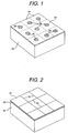
FIG. 1 is an elevational view illustrating initial steps of the method of the present invention; -
FIG. 2 is a view similar toFIG. 1 , but illustrating further steps of the method of the present invention; -
FIG. 3 is a side sectional view illustrating yet a further step of the method of the present invention; -
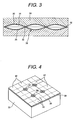
FIG. 4 is a view similar toFIG. 1 , but illustrating a modification thereof; -
FIG. 5 is a view similar toFIG. 2 , but illustrating a modification thereof; and -
FIG. 6 is a view similar toFIG. 3 , but illustrating a modification thereof. - With reference first to
FIG. 1 , in order to manufacture the multi-sheet metallic structure of the present invention, afirst metal sheet 20 is arranged on aplanar support 22. Themetal sheet 20 is preferably planar and an upper surface of theplanar support 22 is preferably horizontal. Furthermore, thesheet 20 may be constructed of any metal alloy or material, such as aluminum. - Still referring to
FIG. 1 , for exemplary purposes only, themetal sheet 20 is illustrated as having nine different selectedportions 24 arranged in a three-by-three grid. It will be understood, of course, that the three-by-three grid for theselected portions 24 is by way of example only and that any pattern may be utilized without deviation from the spirit or scope of the invention. - A blowing
agent 26 is positioned within each of the selectedportions 24. Any conventional blowing agent, such as titanium hydride powder or magnesium hydride powder, may be employed. - With reference now to
FIG. 2 , asecond sheet 30 is then positioned over thefirst sheet 20, such that thesecond sheet 30 overlies each of the selected portions 24 (FIG. 1 ) on thefirst sheet 20. Thereafter, thefirst sheet 20 andsecond sheet 30 are secured together by friction stir welding, thus formingfriction stir welds 32 which enclose each of the selectedportions 24 on thefirst sheet 20. Thefriction stir weld 32, furthermore, is continuous and fully encloses each of the selectedportions 24 on the first sheet and thus effectively seals the blowingagent 26 contained within each selectedportion 24 between thefirst sheet 20 andsecond sheet 30. - With reference now to
FIG. 3 , the blowing agent is heated to a temperature sufficient to decompose the blowing agent, e.g. by heating the now attachedfirst sheet 20 andsecond sheet 30 to a temperature sufficient to decompose the blowing agent. In doing so, the blowing agent decomposes to form a gas, particularly hydrogen gas, which causes thesheets pockets 34 between thesheets second sheets mold 36 which defines the shape of thefinal metal structure 38 following the heating step. Themold 36 may be flat or shaped as shown inFIG. 3 . The shape of the mold determines the shape of the final expanded metal structure. - With reference now to
FIG. 4 , the present invention also enables multi-sheet metal structures having three or even more sheets. For example, after the completion of the friction stir welding operation shown inFIG. 2 , the upper side of thesecond sheet 30 is exposed. This exposed side of thesheet 30 is then divided into a pattern indicated in phantom lines which thus divide the exposed side of thesecond sheet 30 into a plurality of selectedportions 42. Theseselected portions 42 are illustrated inFIG. 4 as a grid in which the center of each selectedportion 42 is centered on intersectingweld lines 32 from the friction stir welding operation between thefirst sheet 20 andsecond sheet 30. It will, of course, be understood that this is by way of example only. - A blowing
agent 44 is then positioned within each selectedportion 42 on the exposed side of thesecond sheet 30. The blowingagent 44 may be the same as the blowing agent 26 (FIG. 1 ) or may be different. - With reference now to
FIG. 5 , athird sheet 46 is then positioned over the exposed side of thesecond sheet 30 so that thethird sheet 46 covers each of the selectedportions 42 defined on the exposed side of thesecond sheet 30. Thereafter, thesecond sheet 30 andthird sheet 46 are secured together by a friction stir welding, thus forming the friction stir welds 48 which extend entirely around each of the selected portions 42 (FIG. 4 ) which form a pattern for the final desired metallic part. - Furthermore, although the
third sheet 46 has been described as overlying the exposed side of thesecond sheet 30, it will be understood, of course, that thethird sheet 46 optionally may overlie the exposed side of thefirst sheet 20. In this event, after thefirst sheet 20 andsecond sheet 30 are attached together, the resulting structure would be flipped so that the exposed side of the first sheet would face upwardly. - After completion of the three-sheet structure illustrated in
FIG. 5 , it is optionally placed into themold 36 and heated to a temperature which exceeds the decomposition temperature of the blowing agent. When this occurs, the blowing agent decomposes, thus releasing a gas, particularly hydrogen gas, and forming the lattice structure illustrated inFIGs. 5 and 6 , in which the patterns on the opposite sides of the structure are offset from each other and interlaced. - From the foregoing, it can be seen that the present invention provides a novel method for forming multi-sheet metallic structures which overcomes the limitations of the previously known methods. In particular, since friction stir welding is utilized to secure the sheets together, the relatively low temperature generated during the friction stir welding process insures against premature decomposition of the blowing agent and allows for greater flexibility of the weld pattern between the sheets. Furthermore, the welds created by friction stir welding are less strong and more ductile than the previously known thermal welds, which is highly desirable during the heating and expansion of the sheets.
- Having described the invention, however, many modifications thereto will become apparent to those of skill in the art to which it pertains without deviation from the spirit of the invention as defined by the scope of the appended claims.
-
- 20
- first metal sheet
- 22
- planar support
- 24, 42
- selected portions, selected areas
- 26, 44
- blowing agent
- 30
- second sheet
- 32, 48
- friction stir weld
- 34
- 46
- third sheet
- 36
- mold
- 38
- final metal structure
Claims (24)
- Multi-sheet metallic structure (38), comprising:a first metal sheet (20),a second metal sheet (30) overlying at least a portion of the first sheet (20),the first sheet (20) being secured to the second sheet (30) by a friction stir weld (32) which encloses at least one selected portion (24) of the first sheet (20) and the second sheet (30), anda blowing agent (26) being sandwiched between the first sheet (20) and the second sheet (30) in the at least one selected portion (24),wherein the structure is formed by heating the blowing agent (26) above its decomposition temperature.
- Multi-sheet metallic structure according to claim 1, further comprising:a third sheet (46) overlying at least a portion of an exposed side of the first sheet (20) or the second sheet (30),the third sheet (46) being secured to the exposed side by a friction stir weld (48) which encloses at least one selected portion (42) of the exposed side and the third sheet (46), anda blowing agent (26; 44) being sandwiched between the exposed side and the third sheet (46),wherein the structure is formed by heating the blowing agent (26; 44) above its decomposition temperature.
- Multi-sheet metallic structure, particularly according to claim 1, obtainable by:- arranging a first metal sheet (20) on a planar support (22),- placing a blowing agent (26) on at least one selected portion (24) of the first sheet (20),- positioning a second metal sheet (30) over the first sheet (20) so that the second sheet (30) overlies the at least one selected portion (24) of the first sheet (20),- friction stir welding the first sheet (20) and the second sheet (30) together in a pattern which encloses the selected portion (24) of the first sheet (20), and- thereafter heating the blowing agent (26) to a temperature sufficient to decompose the blowing agent (26).
- Multi-sheet metallic structure according to any of claims 1 to 3, wherein the first metal sheet (20) and the second metal sheet (30) each comprise or consist of a metal or a metal alloy.
- Multi-sheet metallic structure according to claim 2, wherein the third metal sheet (46) comprises or consists of a metal or a metal alloy.
- Multi-sheet metallic structure according to claim 4 or 5, wherein the first sheet (20) and the second sheet (30) each comprise or consist of aluminum or an aluminum alloy or an alloy comprising aluminum.
- Multi-sheet metallic structure according to claim 5 or 6, wherein the third sheet (46) comprises or consists of aluminum or an aluminum alloy or an alloy comprising aluminum.
- Multi-sheet metallic structure according to any of claims 1 to 7, wherein the at least one selected portion (24; 42) comprises a plurality of separate selected portions (24; 42).
- Multi-sheet metallic structure according to claim 8, wherein the plurality of selected portions (24; 42) are arranged in a lattice.
- Multi-sheet metallic structure according to any of claims 2 to 9, wherein the selected portions (24) between the first sheet (20) and the second sheet (30) form a first lattice, and the selected portions (42) between the exposed side and the third sheet (46) form a second lattice, the first lattice and the second lattice being offset from each other.
- Multi-sheet metallic structure according to any of claims 1 to 10, wherein the blowing agent (26; 44) comprises or consists of titanium hydride powder.
- Multi-sheet metallic structure according to any of claims 1 to 10, wherein the blowing agent (26; 44) comprises or consists of magnesium hydride powder.
- Method for fabricating multi-sheet metallic structures, comprising the follwing steps:- arranging a first metal sheet (20) on a planar support (22),- placing a blowing agent (26) on at least one selected portion (24) of the first sheet (20),- positioning a second metal sheet (30) over the first sheet (20) so that the second sheet (30) overlies the at least one selected portion (24) of the first sheet (20),- friction stir welding the first sheet (20) and the second sheet (30) together in a pattern which encloses the selected portion (24) of the first sheet (20), and- thereafter heating the blowing agent (26) to a temperature sufficient to decompose the blowing agent (26).
- Method according to claim 13, comprising the following further steps:- placing a blowing agent (26; 44) on at least one selected portion (42) of an exposed side of either the first sheet (20) or the second sheet (30) after the welding step and prior to the heating step,- positioning a third metal sheet (46) over the exposed side of the first sheet (20) or the second sheet (30) so that the third sheet (46) overlies the at least one selected portion (42) of the exposed side of the first sheet (20) or the second sheet (30), and- friction stir welding the third sheet (46) and the exposed side of the first sheet (20) or the second sheet (30) together in a pattern which encloses the selected portion (42) of the first sheet (20).
- Method according to claim 13 or 14, wherein the first metal sheet (20) and the second metal sheet (30) each comprise or consist of a metal or a metal alloy, preferably having high formability.
- Method according to claim 14 or 15, wherein the third metal sheet (46) comprises or consists of a metal or a metal alloy.
- Method according to claim 15 or 16, wherein the first sheet (20) and the second sheet (30) each comprise or consist of aluminum or an aluminum alloy or an alloy comprising aluminum.
- Method according to claim 16 or 17, wherein the third sheet (46) comprises or consists of aluminum or an aluminum alloy or an alloy comprising aluminum.
- Method according to any of claims 13 to 18, wherein the blowing agent (26; 44) comprises or consists of titanium hydride powder.
- Method according to any of claims 13 to 18, wherein the blowing agent (26; 44) comprises or consists of magnesium hydride powder.
- Method according to any of claims 13 to 20, wherein the step of placing a blowing agent (26; 44) comprises the steps of placing a blowing agent (26; 44) on a plurality of different selected portions (24) of the first sheet (20), and wherein the step of friction stir welding comprises the step of friction stir welding the first sheet (20) and the second sheet (30) together in a pattern which encloses each of the selected portions (24) of the first sheet (20), and so that each selected portion (24) is sealed from the other selected portions (24).
- Method according to any of claims 14 to 21, wherein the selected portion (42) on the exposed side of the first sheet (20) or the second sheet (30) is offset from the selected portion (24) on the first sheet (20) or the second sheet (30).
- Method according to any of claims 13 to 22, wherein the step(s) of decomposing the blowing agent (26; 44) is/are carried out in a mold (36).
- Use of the multi-sheet structures according to claims 1 to 12 as constructional material, particularly for automobile structures.
Applications Claiming Priority (1)
| Application Number | Priority Date | Filing Date | Title |
|---|---|---|---|
| US11/930,838 US7866531B2 (en) | 2007-10-31 | 2007-10-31 | Multi-sheet structures and method for manufacturing same |
Publications (1)
| Publication Number | Publication Date |
|---|---|
| EP2055421A1 true EP2055421A1 (en) | 2009-05-06 |
Family
ID=40227517
Family Applications (1)
| Application Number | Title | Priority Date | Filing Date |
|---|---|---|---|
| EP08019131A Withdrawn EP2055421A1 (en) | 2007-10-31 | 2008-10-31 | Multi-sheet structures with expanded parts and method for manufacturing same using a blowing agent sandwiched between the sheets |
Country Status (3)
| Country | Link |
|---|---|
| US (1) | US7866531B2 (en) |
| EP (1) | EP2055421A1 (en) |
| JP (1) | JP2009107014A (en) |
Families Citing this family (2)
| Publication number | Priority date | Publication date | Assignee | Title |
|---|---|---|---|---|
| HUE071435T2 (en) * | 2018-10-09 | 2025-09-28 | Outokumpu Oy | Method for manufacturing a crash frame of a battery compartment for battery electric vehicles |
| WO2023077300A1 (en) * | 2021-11-03 | 2023-05-11 | 黄山学院 | Method for modifying surface performance of lightweight alloy |
Citations (6)
| Publication number | Priority date | Publication date | Assignee | Title |
|---|---|---|---|---|
| US3547751A (en) * | 1967-05-02 | 1970-12-15 | Burton D Morgan | Honeycomb core made from sealed continuous thermoplastic sheets |
| US3981753A (en) * | 1968-04-30 | 1976-09-21 | Kennecott Copper Corporation | Stop-weld composition and the method of using it |
| JPH04333326A (en) * | 1991-05-02 | 1992-11-20 | Mitsubishi Kasei Corp | Composite metal material for processing and manufacturing method of metal hollow body |
| US5692881A (en) * | 1995-06-08 | 1997-12-02 | United Technologies Corporation | Hollow metallic structure and method of manufacture |
| US6264880B1 (en) * | 1998-07-22 | 2001-07-24 | The Regents Of The University Of California | Manifold free multiple sheet superplastic forming |
| US20060255098A1 (en) * | 2003-12-19 | 2006-11-16 | The Boeing Company | Friction welded structural assembly and preform and method for same |
Family Cites Families (14)
| Publication number | Priority date | Publication date | Assignee | Title |
|---|---|---|---|---|
| US3319322A (en) * | 1964-06-03 | 1967-05-16 | Olin Mathieson | Method of making a finned heat exchange panel |
| US4603089A (en) | 1983-11-21 | 1986-07-29 | Rockwell International Corporation | Laser welding of sandwich structures |
| GB9125978D0 (en) | 1991-12-06 | 1992-02-05 | Welding Inst | Hot shear butt welding |
| US5449109A (en) | 1993-11-15 | 1995-09-12 | Chuang; Tung-Han | Method for superplastic forming by internal pressure |
| WO1997027045A2 (en) | 1996-01-12 | 1997-07-31 | The Boeing Company | Metal sandwich structure with integral hardpoint |
| US5994666A (en) | 1996-01-12 | 1999-11-30 | The Boeing Company | Multisheet metal sandwich structures |
| US6129261A (en) | 1996-09-26 | 2000-10-10 | The Boeing Company | Diffusion bonding of metals |
| JPH1147859A (en) * | 1997-07-25 | 1999-02-23 | Mitsubishi Heavy Ind Ltd | Manufacturing method of aluminum alloy panel |
| US6168072B1 (en) | 1998-10-21 | 2001-01-02 | The Boeing Company | Expansion agent assisted diffusion bonding |
| US6337471B1 (en) | 1999-04-23 | 2002-01-08 | The Boeing Company | Combined superplastic forming and adhesive bonding |
| JP3646688B2 (en) * | 2001-10-22 | 2005-05-11 | 日産自動車株式会社 | Hydraulic forming method for hollow structural parts |
| FR2831533B1 (en) * | 2001-10-29 | 2004-07-30 | Commissariat Energie Atomique | PROCESS FOR METALLIZING AND / OR SELECTIVELY BRAZING BY A METALLIZATION COMPOSITION OF NON-WETTING OXIDE CERAMIC PIECES BY SAID COMPOSITION |
| JP4233018B2 (en) | 2003-01-17 | 2009-03-04 | 本田技研工業株式会社 | Manufacturing method of closed cross-section structure filled with foam |
| US20050127145A1 (en) | 2003-11-20 | 2005-06-16 | L&L Products, Inc. | Metallic foam |
-
2007
- 2007-10-31 US US11/930,838 patent/US7866531B2/en active Active
-
2008
- 2008-08-28 JP JP2008218878A patent/JP2009107014A/en active Pending
- 2008-10-31 EP EP08019131A patent/EP2055421A1/en not_active Withdrawn
Patent Citations (6)
| Publication number | Priority date | Publication date | Assignee | Title |
|---|---|---|---|---|
| US3547751A (en) * | 1967-05-02 | 1970-12-15 | Burton D Morgan | Honeycomb core made from sealed continuous thermoplastic sheets |
| US3981753A (en) * | 1968-04-30 | 1976-09-21 | Kennecott Copper Corporation | Stop-weld composition and the method of using it |
| JPH04333326A (en) * | 1991-05-02 | 1992-11-20 | Mitsubishi Kasei Corp | Composite metal material for processing and manufacturing method of metal hollow body |
| US5692881A (en) * | 1995-06-08 | 1997-12-02 | United Technologies Corporation | Hollow metallic structure and method of manufacture |
| US6264880B1 (en) * | 1998-07-22 | 2001-07-24 | The Regents Of The University Of California | Manifold free multiple sheet superplastic forming |
| US20060255098A1 (en) * | 2003-12-19 | 2006-11-16 | The Boeing Company | Friction welded structural assembly and preform and method for same |
Also Published As
| Publication number | Publication date |
|---|---|
| US7866531B2 (en) | 2011-01-11 |
| US20090110949A1 (en) | 2009-04-30 |
| JP2009107014A (en) | 2009-05-21 |
Similar Documents
| Publication | Publication Date | Title |
|---|---|---|
| US4114794A (en) | Method of autogenously bonding filter assemblies | |
| JP4245924B2 (en) | Electronic component package and manufacturing method thereof | |
| TWI680551B (en) | Steam room | |
| KR20160075769A (en) | A method of brazing a plate heat exchanger using screen printed brazing material ; a plate heat exchanger manufactured by such method | |
| EP3661679B1 (en) | Powder hot isostatic pressing | |
| EP2055421A1 (en) | Multi-sheet structures with expanded parts and method for manufacturing same using a blowing agent sandwiched between the sheets | |
| JPS6029593B2 (en) | Manufacturing method of Ti-clad steel | |
| US4425299A (en) | Method for bonding sintered metal pieces | |
| EP1347858B1 (en) | Brazing foil preforms and their use in the manufacture of heat exchangers | |
| JPH06155030A (en) | Joined clad plate and its manufacture | |
| WO2002042031A1 (en) | Layered heat-resistant alloy plate and method of producing the same | |
| EP3221072B1 (en) | Process for presintered brazing | |
| JPS58141880A (en) | Joining method of sintered hard alloy | |
| JPS63281767A (en) | Production of laminated heat resistant alloy plate | |
| US5903813A (en) | Method of forming thin dense metal sections from reactive alloy powders | |
| EP3789149A1 (en) | Braze foil quantity control method | |
| JP3798219B2 (en) | Joined body and joining method of iron-based alloy members | |
| GB2075554A (en) | Production of powdered metal articles | |
| JPH01154886A (en) | Manufacture of al clad steel plate | |
| JP4607497B2 (en) | Parallel metal plates of different metals and manufacturing method thereof | |
| JPH0450106B2 (en) | ||
| US6299963B1 (en) | Superplastically formed panel | |
| JPS6321589B2 (en) | ||
| JP4185487B2 (en) | Manufacturing method of steel floor for clean room | |
| JP3798543B2 (en) | Metal composite plate having hollow portion and method for producing the same |
Legal Events
| Date | Code | Title | Description |
|---|---|---|---|
| PUAI | Public reference made under article 153(3) epc to a published international application that has entered the european phase |
Free format text: ORIGINAL CODE: 0009012 |
|
| AK | Designated contracting states |
Kind code of ref document: A1 Designated state(s): AT BE BG CH CY CZ DE DK EE ES FI FR GB GR HR HU IE IS IT LI LT LU LV MC MT NL NO PL PT RO SE SI SK TR |
|
| AX | Request for extension of the european patent |
Extension state: AL BA MK RS |
|
| AKX | Designation fees paid | ||
| STAA | Information on the status of an ep patent application or granted ep patent |
Free format text: STATUS: THE APPLICATION IS DEEMED TO BE WITHDRAWN |
|
| 18D | Application deemed to be withdrawn |
Effective date: 20091107 |
|
| REG | Reference to a national code |
Ref country code: DE Ref legal event code: 8566 |