EP2055230B1 - Drahtlose Shunts mit Speicher - Google Patents
Drahtlose Shunts mit Speicher Download PDFInfo
- Publication number
- EP2055230B1 EP2055230B1 EP08253553.5A EP08253553A EP2055230B1 EP 2055230 B1 EP2055230 B1 EP 2055230B1 EP 08253553 A EP08253553 A EP 08253553A EP 2055230 B1 EP2055230 B1 EP 2055230B1
- Authority
- EP
- European Patent Office
- Prior art keywords
- valve
- radio frequency
- frequency identification
- identification tag
- sensor
- Prior art date
- Legal status (The legal status is an assumption and is not a legal conclusion. Google has not performed a legal analysis and makes no representation as to the accuracy of the status listed.)
- Active
Links
Images


Classifications
-
- A—HUMAN NECESSITIES
- A61—MEDICAL OR VETERINARY SCIENCE; HYGIENE
- A61M—DEVICES FOR INTRODUCING MEDIA INTO, OR ONTO, THE BODY; DEVICES FOR TRANSDUCING BODY MEDIA OR FOR TAKING MEDIA FROM THE BODY; DEVICES FOR PRODUCING OR ENDING SLEEP OR STUPOR
- A61M27/00—Drainage appliance for wounds or the like, i.e. wound drains, implanted drains
- A61M27/002—Implant devices for drainage of body fluids from one part of the body to another
-
- A—HUMAN NECESSITIES
- A61—MEDICAL OR VETERINARY SCIENCE; HYGIENE
- A61B—DIAGNOSIS; SURGERY; IDENTIFICATION
- A61B5/00—Measuring for diagnostic purposes; Identification of persons
- A61B5/0002—Remote monitoring of patients using telemetry, e.g. transmission of vital signals via a communication network
- A61B5/0031—Implanted circuitry
-
- A—HUMAN NECESSITIES
- A61—MEDICAL OR VETERINARY SCIENCE; HYGIENE
- A61B—DIAGNOSIS; SURGERY; IDENTIFICATION
- A61B5/00—Measuring for diagnostic purposes; Identification of persons
- A61B5/03—Measuring fluid pressure within the body other than blood pressure, e.g. cerebral pressure ; Measuring pressure in body tissues or organs
- A61B5/031—Intracranial pressure
-
- A—HUMAN NECESSITIES
- A61—MEDICAL OR VETERINARY SCIENCE; HYGIENE
- A61M—DEVICES FOR INTRODUCING MEDIA INTO, OR ONTO, THE BODY; DEVICES FOR TRANSDUCING BODY MEDIA OR FOR TAKING MEDIA FROM THE BODY; DEVICES FOR PRODUCING OR ENDING SLEEP OR STUPOR
- A61M27/00—Drainage appliance for wounds or the like, i.e. wound drains, implanted drains
- A61M27/002—Implant devices for drainage of body fluids from one part of the body to another
- A61M27/006—Cerebrospinal drainage; Accessories therefor, e.g. valves
-
- A—HUMAN NECESSITIES
- A61—MEDICAL OR VETERINARY SCIENCE; HYGIENE
- A61M—DEVICES FOR INTRODUCING MEDIA INTO, OR ONTO, THE BODY; DEVICES FOR TRANSDUCING BODY MEDIA OR FOR TAKING MEDIA FROM THE BODY; DEVICES FOR PRODUCING OR ENDING SLEEP OR STUPOR
- A61M39/00—Tubes, tube connectors, tube couplings, valves, access sites or the like, specially adapted for medical use
- A61M39/22—Valves or arrangement of valves
-
- A—HUMAN NECESSITIES
- A61—MEDICAL OR VETERINARY SCIENCE; HYGIENE
- A61M—DEVICES FOR INTRODUCING MEDIA INTO, OR ONTO, THE BODY; DEVICES FOR TRANSDUCING BODY MEDIA OR FOR TAKING MEDIA FROM THE BODY; DEVICES FOR PRODUCING OR ENDING SLEEP OR STUPOR
- A61M2205/00—General characteristics of the apparatus
- A61M2205/04—General characteristics of the apparatus implanted
-
- A—HUMAN NECESSITIES
- A61—MEDICAL OR VETERINARY SCIENCE; HYGIENE
- A61M—DEVICES FOR INTRODUCING MEDIA INTO, OR ONTO, THE BODY; DEVICES FOR TRANSDUCING BODY MEDIA OR FOR TAKING MEDIA FROM THE BODY; DEVICES FOR PRODUCING OR ENDING SLEEP OR STUPOR
- A61M2205/00—General characteristics of the apparatus
- A61M2205/32—General characteristics of the apparatus with radio-opaque indicia
-
- A—HUMAN NECESSITIES
- A61—MEDICAL OR VETERINARY SCIENCE; HYGIENE
- A61M—DEVICES FOR INTRODUCING MEDIA INTO, OR ONTO, THE BODY; DEVICES FOR TRANSDUCING BODY MEDIA OR FOR TAKING MEDIA FROM THE BODY; DEVICES FOR PRODUCING OR ENDING SLEEP OR STUPOR
- A61M2205/00—General characteristics of the apparatus
- A61M2205/33—Controlling, regulating or measuring
- A61M2205/3331—Pressure; Flow
- A61M2205/3344—Measuring or controlling pressure at the body treatment site
-
- A—HUMAN NECESSITIES
- A61—MEDICAL OR VETERINARY SCIENCE; HYGIENE
- A61M—DEVICES FOR INTRODUCING MEDIA INTO, OR ONTO, THE BODY; DEVICES FOR TRANSDUCING BODY MEDIA OR FOR TAKING MEDIA FROM THE BODY; DEVICES FOR PRODUCING OR ENDING SLEEP OR STUPOR
- A61M2205/00—General characteristics of the apparatus
- A61M2205/35—Communication
- A61M2205/3507—Communication with implanted devices, e.g. external control
- A61M2205/3523—Communication with implanted devices, e.g. external control using telemetric means
-
- A—HUMAN NECESSITIES
- A61—MEDICAL OR VETERINARY SCIENCE; HYGIENE
- A61M—DEVICES FOR INTRODUCING MEDIA INTO, OR ONTO, THE BODY; DEVICES FOR TRANSDUCING BODY MEDIA OR FOR TAKING MEDIA FROM THE BODY; DEVICES FOR PRODUCING OR ENDING SLEEP OR STUPOR
- A61M2205/00—General characteristics of the apparatus
- A61M2205/50—General characteristics of the apparatus with microprocessors or computers
- A61M2205/52—General characteristics of the apparatus with microprocessors or computers with memories providing a history of measured variating parameters of apparatus or patient
Definitions
- the present invention generally relates to devices and methods for non-invasively storing and accessing data related to medical devices, and more particularly to non-invasively storing and accessing data related to shunts.
- Hydrocephalus is a neurological condition that is caused by the abnormal accumulation of CSF within the ventricles, or cavities, of the brain.
- CSF is a clear, colorless fluid that is primarily produced by the choroid plexus and surrounds the brain and spinal cord.
- CSF constantly circulates through the ventricular system of the brain and is ultimately absorbed into the bloodstream.
- CSF aids in the protection of the brain and spinal cord. Because CSF keeps the brain and spinal cord buoyant, it acts as a protective cushion or "shock absorber" to prevent injuries to the central nervous system.
- Hydrocephalus which affects children and adults, arises when the normal drainage of CSF in the brain is blocked in some way.
- Such blockage can be caused by a number of factors, including, for example, genetic predisposition, intra-ventricular or intra-cranial hemorrhage, infections such as meningitis, head trauma, or the like. Blockage of the flow of CSF consequently creates an imbalance between the amount of CSF produced by the choroid plexus and the rate at which CSF is absorbed into the bloodstream, thereby increasing pressure on the brain, which causes the ventricles to enlarge.
- Hydrocephalus is most often treated by surgically inserting a shunt system that diverts the flow of CSF from the ventricle to another area of the body where the CSF can be absorbed as part of the circulatory system.
- Shunt systems come in a variety of models, and typically share similar functional components. These components include a ventricular catheter which is introduced through a burr hole in the skull and implanted in the patient's ventricle, a drainage catheter that carries the CSF to its ultimate drainage site, and optionally a flow-control mechanism, e.g., shunt valve, that regulates the one-way flow of CSF from the ventricle to the drainage site to maintain normal pressure within the ventricles.
- a flow-control mechanism e.g., shunt valve
- One problem encountered with the use of shunt systems is the difficultly in accessing data related to a shunt system implanted in a patient.
- One current technique for accessing data involves recording data related to a shunt system in a patient's written medical file. While this technique is advantageous in that it centrally collects patient data, the written medical file is not always accessible, for example, if the patient has an emergency and is taken to a hospital without access to the written medical file. Furthermore, tracking historical data using this technique can be cumbersome.
- WO 2005/046467 discloses a medical device for implantation in a body comprising: one or more sensors for sensing a physiologically or clinically relevant parameter; and telemetric communications means for telemetrically transmitting data related to a parameter sensed by the one or more sensors to a remote device.
- Preferred medical devices are heart valve devices, vascular grafts and stents.
- Preferred sensors are pressure sensors, acoustic sensors and electrochemical sensors.
- US 2002/052563 discloses a device and method for measuring and communicating parameters of a brain, tissue or other organs.
- the device Includes a sensor to sense the parameter of interest.
- the sensor is preferably located at the distal end of a probe.
- the sensor is part of a passive system that allows pressure or temperature measurements to be made and communicated to an attending practitioner when the passive system receives power from an external source.
- the sensor is part of a system having a long-term energy source and storage system that allows pressure or temperature measurements to be taken periodically or upon demand, stored and then communicated to an attending practitioner as desired.
- a method for measuring and communicating parameters of a brain, tissue or other organs are also disclosed.
- the method includes the steps of providing a sensor to sense the parameter of interest, implanting the sensor in or near a target in the brain, tissue or other organ where the parameter of interest may be sensed, providing a reaction device where the parameter may be displayed, processed or cause action to be taken, sensing the parameter or interest, communicating the sensed parameter to the reaction device and displaying or processing the parameter or causing action to be taken in response to the parameter.
- US 6 248 080 discloses an implantable medical device having an hermetically sealed enclosure housing electrical and electronic circuitry and a battery for powering such circuitry which is connected to an Intracranial lead or pigtail which measures or senses intracranial physiologic signals such as intracranial fluid pressure and/or temperature.
- the implantable medical device is preferably implanted subcutaneously beneath a patient's skin and telemeters stored data or real-time-sensed data to an external device which may be configured to combine barometric pressure data with intracranial pressure data to derive intracranial gage pressure.
- the implantable medical device and its associated lead reduce the risk of intracranial infections.
- WO 01/21066 discloses an implantable intracranial pressure monitor, which can couple to existing fluid shunting systems as well as other internal monitoring probes.
- the implant sensor produces an analogue data signal which is then converted by electronic means to a digital pulse by generation of a spreading code signal and then transmitted to a location outside the patient by means of a radio-frequency transmitter to an external receiver.
- the implanted device can receive power from an internal source as well as an inductive external source. Remote control of the implant is also provided by a control receiver which passes commands from an external source to the implant system logic.
- Alarm parameters can be programmed into the device which are capable of producing an audible or visual alarm signal.
- the utility of the monitor can be greatly expanded by using multiple pressure sensors simultaneously or by combining sensors of various physiological types.
- US 2007/167867 discloses a system for measuring and converting to an observer intelligible form an internal physiological parameter of a medical patient.
- the system allows transcutaneous telemetry of the measured information intracranial pressure via a system which includes a patient implanted sensor module and a processing and display module which is external of the patient and optically coupled to the sensor module via an external coupling module.
- a sensor within the implanted module transduces the measured information and a near infrared (NIR) emitter transmits this telemetry information when interrogated by the complementary external coupling module.
- NIR near infrared
- a set of tuned inductor-crystal circuits versus inductor-crystal comprised in part of a cylindrical crystal oscillator whose resonant frequency is sensed by a dipper circuit arrangement is provided.
- Power for the sensor module is derived inductively through rectification of a transcutaneously-applied high-frequency alternating electromagnetic field which is generated by a power source within the external coupling module.
- a computer within the processing and display module calculates the parameter value from the telemetry signal and represents this data either in numerical, graphical, or analogue format.
- the invention provides an implantable valve and a method as defined by the independent claims. Optional features are included in the dependent claims.
- methods and devices for storing and accessing data related to an implantable medical device such as an implantable valve
- the methods and devices are particularly useful in the context of valves for monitoring intra-ventricular pressure.
- they can allow data related to a pressure sensor (or, for example, temperature or flow sensors) in an implantable valve to be stored on and retrievable from an implantable radio frequency identification (RFID) tag associated with a pressure sensor and/or an implantable valve, thereby providing convenient and reliable access to data related to the implantable valve.
- RFID radio frequency identification
- FIGS. 1 and 2 illustrate one exemplary embodiment of an implantable valve 100 that includes a radio frequency identification (RFID) tag 114.
- the valve 100 can be used alone or in combination with a pressure sensor assembly 118 that has a pressure sensor 900 therein, and/or other pressure sensor assemblies disposed upstream or downstream of the valve 100.
- RFID tag 114 can be disposed inside the valve 100, but in other examples, the RFID tag 114 can be disposed outside the valve or any distance apart from the valve and/or the sensor 900. In many embodiments, the RFID tag 114 can be offset from the pressure sensor to facilitate communication.
- the RFID tag 114 can store and communicate data which, for example, can be related to, for example, the valve 100, the pressure sensor 900, and/or a patient.
- the implantable valve 100 can have virtually any configuration, and a variety of implantable valves known in the art can be used, as shown in FIG. 1 the implantable valve 100 has a valve housing 102 with proximal and distal ends 104a, 104b.
- the housing 102 can have virtually any configuration, shape, and size, preferably one making the housing 102 suitable for subcutaneous implantation.
- Fluid e.g., CSF
- Fluid can flow through the housing 102 from an inlet (fluid entry) port 106 at the proximal end 104a and out an outlet (fluid exit) port 110 at the distal end 104b.
- the location and size of the ports 106, 110 can vary, but in many embodiments they can be adapted to allow fluid to flow therethrough and into and out of the housing 102.
- the proximal and distal ends 104a, 104b of the valve 100 can each be open and adapted to couple to another medical device, such as a catheter.
- the valve housing 102 can contain a valve assembly 112 for controlling the flow of fluid from the inlet port 106 to the outlet port 110, and a pressure sensor assembly 118 for measuring a pressure of the fluid flowing through the valve 100, as will be described in more detail below with respect to FIG. 2 .
- valve assembly 112 and the pressure sensor assembly 118 of the valve 100 are shown in-line with one another and with the inlet port 106 and outlet port 110, and the pressure sensor assembly 118 is positioned upstream of the valve 100, the valve 100 can have a variety of other configurations, and the valve assembly 112, the pressure sensor assembly 118, the inlet port 106, and the outlet port 110 can be positioned at various locations relative to one another.
- the inlet port 106 can extend at a right angle with respect to the pressure sensor assembly 118 such that the inlet port 106 extends in a direction substantially transverse to a longitudinal axis of the valve 100.
- the valve assembly 112 can also have a variety of configurations.
- valves are described in U.S. Patent Nos. 3,886,948 , 4,332,255 , 4,387,715 , 4,551.128 , 4,595,390 , 4,615,691 , 4,772,257 , and 5,928,182 .
- the pressure sensor assembly 118 can include the sensor 900, a sensor housing 902, a backing 904, and an RFID tag 114.
- the sensor housing 902 can have a variety of shapes and sizes, but in the illustrated exemplary embodiment the sensor housing 902 has a generally hemi-spherical or domed portion 910 that defines a reservoir therein.
- the sensor housing 902 can also include an inlet tube 912 that couples to the inlet port 106 of the valve 100, and an outlet tube 914 that couples to the outlet port 110 of the valve 100.
- the sensor housing 902 When the sensor housing 902 is mated to the backing 904, the reservoir chamber defined by the housing 902 is sealed, thereby allowing fluid to flow from the inlet port 106 of the valve 100, through the sensor housing 902, through the valve 906, and out the outlet port 110 in the valve 100.
- the sensor housing 902 can also include a flange 916 formed around a base of the domed portion 910 to allow the device to be secured to tissue.
- the flange 916 can include one or more suture holes formed therein for receiving suture to attach the flange 916 to tissue.
- the pressure sensor 900 such as the exemplary pressure sensor 300 shown in FIG. 3 , can be formed on a microchip which can be coupled to an antenna 117 for communicating a sensed pressure to an external device.
- the antenna 117 can have a substantially circular shape, and the microchip sensor can be coupled to the antenna 117 which can, for example, be in the form of a gold microcoil,
- the sensor 900 and the RFID tag 114 can also each include a fluid-impermeable coating, as further described below, to protect the sensor 900 and the RFID tag 114 from fluid flowing through the sensor housing 902 or from other fluid.
- the size of sensor can vary, but in one exemplary embodiment the microchip sensor 900 has a size that is in the range of about 1 mm to 3 mm, and more preferably that is about 2.5 mm 2 .
- Exemplary embodiments of a pressure sensor and antenna are described in more detail in U.S. Patent No. 5,321,989 , U.S. Patent No. 5,431,057 .
- EP Patent No. 1 312 302 and in co-pending, commonly assigned U.S. Patent Application No. 10/907,665 , entitled "Pressure Sensing Valve” by Mauge et al., filed April 11, 2005 (now published as U.S. Publication No. 2006-0211946 A1 .
- the senor 900 which is disposed within the sensor housing 902, measures the pressure of fluid flowing through the sensor housing 902.
- the inlet port 106 of the valve 100 can be coupled to the ventricular catheter 120 for receiving fluid flow from one or more ventricles, and the outlet port 110 can be coupled to a drainage catheter 122.
- the pressure of the fluid will apply a force to active sensor membranes formed on the sensor 900, thereby allowing the fluid pressure to be measured.
- the sensed pressure can be communicated, via the antenna, to an external reading device, as described further below. Performance of the sensor membranes can vary with factors such as temperature, its age, and its maintenance, and the membranes may need to be calibrated to correct for such variance.
- Calibration can vary from sensor to sensor. Calibration information, such as calibration coefficients and drift compensation values particular to the sensor 900, can be stored in the RFID tag 114 (as well as other kinds of information, which will be described in more detail below). Stored calibration information can be read by an external device, identified as associated with this particular sensor 900, and used to calibrate the sensor 900.
- An external reading device e.g., a radio frequency (“RF") reader, can inductively couple to the RFID tag 114 and non-invasively communicate data for storage to the RFID tag 114 and/or non-invasively receive stored data from the RFID tag 114.
- RF radio frequency
- the sensor 900 and the RFID tag 114 can be disposed in the sensor housing 902, although the location of the RFID tag 114 can vary widely.
- the RFID tag 114 can be remote from the sensor 900 and valve 100, for example, disposed outside the housing 902 or implanted in another area of the body.
- the sensor 900 and the RFID tag 114 can be physically separate, without a physical link or connection (e.g., a mechanical, electrical, or communication link or connection) between them.
- a physical link or connection e.g., a mechanical, electrical, or communication link or connection
- the valve 100 may be limited in size, and the RFID tag 114 can be located outside the valve 100 while the sensor 900 can be located within the valve 100.
- a sensor having a microchip (as described above in connection with FIG. 3 ) can dedicate the microchip to sensor functionality, and accordingly retain a relatively small size, while a separate RFID tag can provide storage related that sensor.
- the RFID tag can be "retrofitted" to previously implanted medical devices, for example, which were implanted without an RFID tag and do not have its storage and communication abilities. In some embodiments, even though the RFID tag and the pressure sensor, for example, are physically separate from one another (as in FIGS.
- their respective antennas can be located in proximity or adjacent to one another, so that both devices can be read with an external reading device in one location.
- the external reading device may communicate with each device using a different frequency, protocol, etc., as will be described in more detail below.
- the valve 100 (or other device in which the RFID tag 114 is embedded, or associated with) can have features to protect the RFID tag 114.
- the sensor assembly 118 of the valve 100 can include a washer 908, which can be provided to seat the sensor 900 and/or the RFID tag 114, such that the washer 908 and the sensor 900 and/or the RFID tag 114 are positioned against the backing 904.
- the washer 908 can also be configured such that the sensor 900 and/or the RFID tag 114 are sub-flush with the washer 908, for example, to protect the sensor 900 and the RFID tag 114 from potential damage when the domed portion 910 of the housing 902 is depressed.
- the sensor assembly 118 can also include a needle guard 906 for protecting the sensor 900 and the RFID tag 114.
- the needle guard 906 can protect the sensor 900 and the RFID tag 114 from coming into contact with the domed portion 910 of the housing 902 when the domed portion 910 is depressed, as the needle guard 906 can be positioned between the sensor 900 and the domed portion 910.
- the needle guard 906 can also be provided to protect the sensor 900 and the RFID tag 114 from a needle being inserted through the domed portion 910 of the sensor housing 902.
- the needle guard 906 has a substantially planar, circular shape and it is adapted to be disposed between the domed portion 910 of the housing 902 and the sensor 900.
- the needle guard 906 can, however, include an opening formed therein and positioned adjacent to the microchip sensor 900 to allow fluid flowing through the sensor housing 902 to come into contact with the sensor 900.
- a flange or protective member 918 is disposed over the opening, without blocking the opening from fluid flow, to prevent a user from accidentally inserted a needle through the opening. Further information on these features can be found in U.S. Publication No. 2006-0211946 A1 , referenced above.
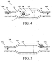
- FIG. 4 is a schematic illustration of one embodiment of the implantable valve 100 of FIGS. 1 and 2 showing one possible location of the RFID tag 114 disposed within the housing 102.
- the housing 102 has a substantially linear configuration with a reservoir 108 having a larger area than ports 106, 110, which can be advantageous for checking the shunt's patency, tapping the CSF, to administer therapy, or to house pressure or flow sensors.
- fluid e.g., CSF
- the RFID tag 114 for storing data and for communicating stored data, is disposed in the sensor housing 902 that defines the reservoir 108.
- the RFID tag 114 can for example be disposed in a wide variety of locations. For example, it can be disposed in the valve 100, disposed at a location proximate to the valve 100, or implanted at any other location within the patient associated with the valve 100, including at a location remote from the valve 100.
- FIG. 5 shows another schematic example of the valve 100 in which the RFID tag 114 is disposed proximate to the distal end 104b of the valve 100.
- FIG. 6 shows an alternate schematic example of the valve 100 in which the RFID tag 114 is disposed outside the valve 100, in this example embodiment proximate to the proximal end 104a of the valve 100, although the RFID tag 114 can be implanted any distance from the valve 100.
- FIG. 5 shows another schematic example of the valve 100 in which the RFID tag 114 is disposed proximate to the distal end 104b of the valve 100.
- FIG. 6 shows an alternate schematic example of the valve 100 in which the RFID tag 114 is disposed outside the valve 100,
- the reservoir 108 can have any size and shape, including a shape accommodating the RFID tag 114.
- the reservoir 108 has a substantially rectangular shape, while in the embodiment shown in FIG. 7 , the reservoir has a substantially circular shape at its proximal end and a substantially rectangular shape at its distal end.
- the RFID tag 114 can be non-implantable and can be embedded or housed in a RFID bracelet, key fob, card, etc., to hold information, and issued or given to a patient.
- the housing 102 can be formed from a variety of materials. In an exemplary embodiment, however, the housing 102 is formed from a flexible, biocompatible material. Suitable materials include, for example, polymers such as silicones, polyethylene, and polyurethanes, all of which are known in the art. The housing 102 can also optionally be formed from a radio-opaque material. A person skilled in the art will appreciate that the materials are not limited to those listed herein and that a variety of other biocompatible materials having the appropriate physical properties to enable the desired performance characteristics can be used.
- the valve 100 and/or the RFID tag 114 can also optionally include a coating 116 that is adapted to hermetically seal all or at least a portion of the valve 100, the RFID tag 114, and/or other components such as a sensor, an antenna, a connector, etc.
- the coating 116 can be applied to only a portion of the RFID tag 114 that could be exposed to fluid, or it can be applied to the RFID tag 114, and optionally the valve 100.
- the RFID tag 114 and the valve 100 can be coated separately with different coatings or together in a single coating. In the embodiment shown in FIG. 4 in which the RFID tag 114 is disposed in the valve 100, the RFID tag 114 is preferably pre-coated prior to coupling the sensor assembly to the housing 102.
- the RFID tag 114 can be appropriately positioned.
- An adhesive or other mating technique can be used to affix the RFID tag 114 within the housing 102, such as in the embodiment shown in FIG. 5 , however, in some embodiments it can be useful to allow the RFID tag 114 to be removed from the valve 100 if necessary.
- valve 100 can be coated after the RFID tag 114 is disposed in the valve 100 or located elsewhere to form a protective sheath over the RFID tag 114 and the housing 102.
- the ports 106, 110 can be protected from any coating applied thereto, formed after the coating is applied, or be cleared of any coating applied thereto to allow fluid to flow therethrough.
- only certain components of the valve 100 can be coated.
- a person skilled in the art will appreciate that a variety of other techniques can be used to seal the RFID tag 114 and/or other components of the valve 100.
- the material used to form the coating 116 can vary, and a variety of techniques can be used to apply the coating.
- suitable materials include polyurethane, silicone, solvent-based polymer solutions, and any other polymer that will adhere to the components to which it is applied to, and suitable techniques for applying the coating include spray-coating or dip-coating.
- the shape, technical specifications, and size of the RFID tag can vary widely (as can the RFID tag 114 of FIGS. 1 and 2 ).
- a relatively small RFID tag can be used so as to minimize the footprint of the tag in the device, for example with dimensions in a range of about 5mm to 10mm, but in other embodiments, tags with dimensions of about 3mm to 50 mm can be used and any size is possible.
- the RFID tag 114 can be adapted to be in communication with an external device (e.g., by having an antenna) and to store data.
- the RFID tag 114 can have any shape, such as elliptical, circular, or rectangular (including square), and can have virtually any size.
- the RFID tag 114 can be an off the-shelf component.
- Table 1 lists, by way of example only, available RFID tags suitable for use with the devices and methods described herein. Passive as well as semi-passive and active tags can be used, although semi-passive and active tags sometimes are larger than passive tags because they can incorporate an internal battery, e.g., for power purposes.
- the RFID tag 114 can store and/or communicate various types of data.
- the types of data stored can be selected by a user.
- the data can be related to a valve or any other implanted device(s), a patient associated with the valve, the RFID tag, sensed or measured values (including historical values), and/or characteristics of fluid flowing through the valve or valve assembly.
- Non-limiting examples of data related to the valve 100 (or other devices) can include date of device manufacture, device type (e.g., fixed or programmable), device identifier code, and device maintenance history.
- Non-limiting examples of data related to a patient can include patient identification (e.g., name, identifying code such as Social Security Number, age, etc.), medical history information (e.g., dates of pervious doctor examination(s), disease history, etc.), and date of valve implantation.
- patient identification e.g., name, identifying code such as Social Security Number, age, etc.
- medical history information e.g., dates of pervious doctor examination(s), disease history, etc.
- data related to the RFID tag 114 can include available memory space, date of tag manufacture, date of tag implantation, tag type, tag identifier code, and tag maintenance history.
- Non-limiting examples of data related to implanted sensors or sensed characteristics can include current pressure setting (e.g., a rate of fluid flow through the valve assembly 112), previous pressure setting(s), date(s) of programming/adjustments (if the valve 100 is programmable), calibration parameter(s), settings of previous calibration parameter(s), dates of previous calibration parameter(s), reasons for modifying previous calibration parameter(s) (e.g., adverse medical reactions such as fever or headache), and drift compensation values.
- information related to a pressure sensor such as date of implantation, sensor type, sensor ID, values read, zeroing of the sensor, date of zeroing, specific pressure reading and date taken, can be stored.
- Storing and communicating characteristic data such as calibration parameters and drift compensation values can include polynomial coefficients to calculate an actual pressure value from a measured pressure value.
- the RFID tag 114 can store such data and allow an external RF reader to obtain a correct measurements from the valve 100 without having to depend on external storage devices.
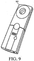
- the RFID tag 114 can be adapted to interact with a wireless signal 500 from an external reading device, such as an RF telemetry device 502 (shown in more detail in FIG. 9 ).
- the reading device 502 can emit a signal 500 at one frequency or over a range of frequencies and can receive a response thereto, e.g., from the RFID tag 114 or a sensor.
- the RF telemetry device 502 can include an RF module (e.g., transmitter and receiver), a control unit (e.g., microcontroller), a coupling element to the transponder (e.g., antenna), and an additional interface (e.g., Recommended Standard (RS) 232, RS-485, Firewire, USB, Bluetooth, ZigBee, etc.) to enable communication with another external device (e.g., a personal computer).
- the RF telemetry device 502 can provide the power required by the RFID tag 114 to operate, e.g., through the coupling element.
- RFID tag 8 can be positioned adjacent to the RFID tag 114 to telemetrically communicate with the RFID tag 114, and thereby obtain and/or transmit data. Further information on the use of such RFID tags, including techniques for interrogating them and examples of them, can be obtained from U.S. Patents No. 6,025,725 , and 6,278,379 , and U.S. Patent Application Publication No. 20040134991 .
- multiple RFID tags and/or other devices capable of wireless communication can be implanted in a patient.
- Multiple RF telemetry devices can be used to communicate with these devices.
- the RF telemetry device can provide the ability to communicate with multiple devices, using different frequencies, different communication protocols, and so on.
- the same RF telemetry device 502 can obtain data from both the pressure sensor and the RFID tag, which as mentioned previously can have antennas located in proximity to one another to facilitate such communication.
- the RF telemetry device 502 can read identification data, such as serial numbers, from the sensor and/or the RFID tag to identify from which device it is receiving data.
- the RFID tag 114 can store data related to not one but a plurality of implanted medical devices, which may be devices that were implanted concurrently with the RFID tag 114 or those being "retrofitted” or “upgraded” with later implantation of an RFID tag.
- the RF telemetry device 502 can read from the RFID tag identification data (and other data) for each of a plurality of implanted devices.
- the RFID tag can store and output data so as to associate it with the implanted device to which it relates, for example via a table correlating device identifiers with data values.
- a method for obtaining data related to medical device such as the valve and/or pressure sensor of FIGS. 1-2 .
- the inlet port 106 of the valve 100 can be coupled to a proximal end of a ventricular catheter 120 that has had its distal end positioned in a patient's ventricle.
- the valve 100 can be implanted in a patient, such as a patient's shoulder area, while the typically more flexible catheter can extend through the patient to the ventricle.
- a drainage catheter 122 can be coupled to the outlet port 110 of the valve 100, in which the drainage catheter can extend through the patient to an area where excess fluid can safely drain.
- the rate of fluid flowing through the valve 100 from the inlet port 106 to the outlet port 110 can for example be controlled by the valve assembly 112.
- Data related to the valve 100 can be obtained at an external reading device (e.g., using the RF telemetry device 502) from an antenna coupled to the RFID tag 114 that is associated with the valve 100.
- the RFID tag 114 is disposed in a valve 100 implanted in a shoulder area of a patient (shown for simplicity without catheters in communication with either of the ports 106, 110).
- the valve can be implanted virtually anywhere, for example subcutaneously behind the ear, or on the head, torso, etc.
- the RFID tag 114 can be disposed outside the valve 100, at a location proximate or remote to the valve 100.
- the method can include implanting the RFID tag 114 concurrently or subsequently (e.g., as a replacement or retrofit) with the valve or other medical device.
- multiple pressure sensor assemblies can be used, each with an associated RFID tag, and the pressure sensor assemblies can be disposed at various locations relative to one another, not necessarily in a valve.
- the use of multiple pressure sensor assemblies can be particularly advantageous as it can allow a differential pressure of the system to be obtained.
- the differential pressure of the system should be equal to the operating pressure of the system, thus indicating whether the system is performing properly- CSF can flow from a patient's ventricle through a catheter (or other medical device) to the inlet port 1 Q6 and through the valve 100.
- the pressure of fluid flowing through the reservoir 108 of the valve 100 can correlate to the patient's ICP despite the valve's implantation at a location other than the patient's ventricle.
- the RFID tag 114 can be disposed outside the valve 100, at a location proximate or remote to the valve 100.
- biocompatible materials include, by way of non-limiting example, composite plastic materials, biocompatible metals and alloys such as stainless steel, titanium, titanium alloys and cobalt-chromium alloys, glass, and any other material that is biologically compatible and non-toxic to the human body.
Landscapes
- Health & Medical Sciences (AREA)
- Life Sciences & Earth Sciences (AREA)
- Engineering & Computer Science (AREA)
- Biomedical Technology (AREA)
- Heart & Thoracic Surgery (AREA)
- Animal Behavior & Ethology (AREA)
- Veterinary Medicine (AREA)
- Public Health (AREA)
- General Health & Medical Sciences (AREA)
- Hematology (AREA)
- Anesthesiology (AREA)
- Pathology (AREA)
- Surgery (AREA)
- Molecular Biology (AREA)
- Medical Informatics (AREA)
- Biophysics (AREA)
- Physics & Mathematics (AREA)
- Otolaryngology (AREA)
- Ophthalmology & Optometry (AREA)
- Neurology (AREA)
- Computer Networks & Wireless Communication (AREA)
- Neurosurgery (AREA)
- Pulmonology (AREA)
- Measuring And Recording Apparatus For Diagnosis (AREA)
- Indication Of The Valve Opening Or Closing Status (AREA)
- Arrangements For Transmission Of Measured Signals (AREA)
Claims (20)
- Implantierbares Ventil (100), umfassend:ein Ventilgehäuse (102), geeignet zur Aufnahme eines Fluidstroms dadurch zwischen einem Ventileinlass (106) und einem Ventilauslass (110);Ventilbaugruppe (112), angeordnet im Ventilgehäuse und geeignet zur Steuerung eines Durchflusses von Fluid, das durch das Ventilgehäuse strömt; undein Funkfrequenz-Identifikationsetikett (114), angeordnet im Ventilgehäuse und geeignet zur Speicherung von Daten, wobei das Funkfrequenz-Identifikationsetikett eine Antenne zur Übermittlung gespeicherter Daten an ein externes Lesegerät enthält;wobei das Funkfrequenz-Identifikationsetikett in oder nahe einem im Ventilgehäuse gebildeten Reservoir (108) angeordnet ist.
- Implantierbares Ventil (100) nach Anspruch 1, ferner umfassend einen Sensor (900), der im Ventilgehäuse (102) angeordnet und zur Messung eines Drucks des Fluids, das durch das Ventilgehäuse strömt, geeignet ist.
- Implantierbares Ventil (100) nach Anspruch 2, wobei das Funkfrequenz-Identifikationsetikett (114) Kalibrierdaten zur Kalibrierung des vom Sensor (900) gemessenen Drucks speichert.
- Implantierbares Ventil (100) nach Anspruch 2, wobei das Funkfrequenz-Identifikationsetikett (114) in einem Abstand vom Sensor (900) angeordnet ist.
- Implantierbares Ventil (100) nach Anspruch 2, wobei der Sensor (900) eine Antenne (117) für die Kommunikation mit einem externen Lesegerät (502) enthält.
- Implantierbares Ventil (100) nach Anspruch 1, wobei das Funkfrequenz-Identifikationsetikett (114) nahe einem beliebigen von dem Ventileinlass (106) des Ventilgehäuses (102) und dem Ventilauslass (110) des Ventilgehäuses angeordnet ist.
- Implantierbares Ventil (100) nach Anspruch 1, wobei das Funkfrequenz-Identifikationsetikett (114) Daten zu einem Patienten speichert.
- Implantierbares Ventil (100) nach Anspruch 1, wobei das Funkfrequenz-Identifikationsetikett (114) eine Druckeinstellung der Ventilbaugruppe (112) speichert, die den Durchfluss des Fluids steuert, das durch das Ventilgehäuse (102) strömt.
- Implantierbares Ventil (100) nach Anspruch 1, wobei das Funkfrequenz-Identifikationsetikett (114) einen Identifikator speichert, der ein beliebiges von dem implantierbaren Ventil, einem im Ventilgehäuse (102) angeordneten Drucksensor (900) und einem zum implantierbaren Ventil gehörenden Patienten identifiziert.
- Implantierbares Ventil (100) nach Anspruch 1, ferner umfassend:einen Drucksensor (900), geeignet zur Messung eines Drucks des Fluids, das durch das Ventilgehäuse (102) strömt; undwobei das Funkfrequenz-Identifikationsetikett (114) mit dem Drucksensor assoziiert ist und zur Speicherung von Daten zum Drucksensor geeignet ist.
- Implantierbares Ventil (100) nach Anspruch 10, wobei der Drucksensor (900) im Ventilgehäuse (102) angeordnet ist.
- Implantierbares Ventil (100) nach Anspruch 10, wobei der Drucksensor (900) und das Funkfrequenz-Identifikationsetikett (114) mit einer fluidundurchlässigen Beschichtung beschichtet sind.
- Implantierbares Ventil (100) nach Anspruch 10, wobei das Funkfrequenz-Identifikationsetikett (114) zur Speicherung von Anamnesedaten eines Patienten geeignet ist.
- Implantierbares Ventil (100) nach Anspruch 10, wobei das Funkfrequenz-Identifikationsetikett (114) außerdem mit einem zweiten Sensor assoziiert und zur Speicherung von Daten zum zweiten Sensor geeignet ist.
- Verfahren, umfassend:Verwendung eines externen Lesegeräts (502) zur telemetrischen Gewinnung von Daten von einem Funkfrequenz-Identifikationsetikett (114), das in einem Ventilgehäuse (102) eines vorimplantierten Ventils (100) angeordnet ist, wobei das Funkfrequenz-Identifikationsetikett zur Speicherung von Ventildaten geeignet ist und eine Antenne zur Übermittlung gespeicherter Daten an das externe Lesegerät enthält;wobei das Funkfrequenz-Identifikationsetikett nahe einem im Ventilgehäuse gebildeten Reservoir (108) angeordnet ist.
- Verfahren nach Anspruch 15, wobei das Funkfrequenz-Identifikationsetikett (114) eine Druckmessung speichert, die von einem im Ventil (100) angeordneten Drucksensor (900) gewonnen wird.
- Verfahren nach Anspruch 16, ferner umfassend Kommunikation mit dem Drucksensor (900) und dem Funkfrequenz-Identifikationsetikett (114) auf derselben Frequenz mithilfe des externen Lesegeräts (502).
- Verfahren nach Anspruch 15, ferner umfassend telemetrische Gewinnung gespeicherter Daten aus dem Funkfrequenz-Identifikationsetikett (114) durch Positionieren des externen Lesegeräts (502) in der Nähe des Funkfrequenz-Identifikationsetiketts.
- Verfahren nach Anspruch 15, ferner umfassend Programmieren des Funkfrequenz-Identifikationsetiketts (114) mit dem externen Lesegerät (502).
- Verfahren nach Anspruch 15, wobei Gewinnung von Daten Gewinnung von Daten zu einem von Kalibrierdaten für den Drucksensor (900), Patientendaten, klinische Anamnese, Identifikationsdaten für das Ventil (100) und Identifikationsdaten für den im Ventil (100) angeordneten Drucksensor einschließt.
Applications Claiming Priority (1)
| Application Number | Priority Date | Filing Date | Title |
|---|---|---|---|
| US11/931,187 US8480612B2 (en) | 2007-10-31 | 2007-10-31 | Wireless shunts with storage |
Publications (2)
| Publication Number | Publication Date |
|---|---|
| EP2055230A1 EP2055230A1 (de) | 2009-05-06 |
| EP2055230B1 true EP2055230B1 (de) | 2017-09-06 |
Family
ID=40293654
Family Applications (1)
| Application Number | Title | Priority Date | Filing Date |
|---|---|---|---|
| EP08253553.5A Active EP2055230B1 (de) | 2007-10-31 | 2008-10-30 | Drahtlose Shunts mit Speicher |
Country Status (5)
| Country | Link |
|---|---|
| US (2) | US8480612B2 (de) |
| EP (1) | EP2055230B1 (de) |
| AU (1) | AU2008237564B2 (de) |
| CA (2) | CA2922068A1 (de) |
| CO (1) | CO6050052A1 (de) |
Families Citing this family (55)
| Publication number | Priority date | Publication date | Assignee | Title |
|---|---|---|---|---|
| EP1177002B1 (de) * | 1999-03-17 | 2005-11-30 | Medtronic, Inc. | Werkzeug zum einstellen eines implantierbaren und einstellbaren durchflussregelventils |
| US7585280B2 (en) | 2004-12-29 | 2009-09-08 | Codman & Shurtleff, Inc. | System and method for measuring the pressure of a fluid system within a patient |
| US8248232B2 (en) * | 2006-01-25 | 2012-08-21 | Greatbatch Ltd. | Hermetically sealed RFID microelectronic chip connected to a biocompatible RFID antenna |
| US9204812B2 (en) * | 2007-10-31 | 2015-12-08 | DePuy Synthes Products, LLC | Wireless pressure sensing shunts |
| US8454524B2 (en) | 2007-10-31 | 2013-06-04 | DePuy Synthes Products, LLC | Wireless flow sensor |
| US8480612B2 (en) | 2007-10-31 | 2013-07-09 | DePuy Synthes Products, LLC | Wireless shunts with storage |
| US7842004B2 (en) | 2007-10-31 | 2010-11-30 | Codman & Shurtleff, Inc. | Wireless pressure setting indicator |
| RU2464048C2 (ru) | 2008-04-17 | 2012-10-20 | Аллерган, Инк. | Имплантируемый порт доступа и система его крепления |
| US9023063B2 (en) | 2008-04-17 | 2015-05-05 | Apollo Endosurgery, Inc. | Implantable access port device having a safety cap |
| US8715158B2 (en) | 2009-08-26 | 2014-05-06 | Apollo Endosurgery, Inc. | Implantable bottom exit port |
| US8506532B2 (en) | 2009-08-26 | 2013-08-13 | Allergan, Inc. | System including access port and applicator tool |
| US8708979B2 (en) | 2009-08-26 | 2014-04-29 | Apollo Endosurgery, Inc. | Implantable coupling device |
| DE102009029159A1 (de) * | 2009-09-03 | 2011-03-17 | Robert Bosch Gmbh | Fluideinspritzsystem |
| US8882728B2 (en) | 2010-02-10 | 2014-11-11 | Apollo Endosurgery, Inc. | Implantable injection port |
| EP2564339A4 (de) | 2010-04-30 | 2015-05-06 | Spm Flow Control Inc | Maschinen, systeme, computerimplementierte verfahren und computerprogrammprodukte zur prüfung und zertifizierung einer öl- und gasausrüstung |
| US20110270025A1 (en) | 2010-04-30 | 2011-11-03 | Allergan, Inc. | Remotely powered remotely adjustable gastric band system |
| US8992415B2 (en) | 2010-04-30 | 2015-03-31 | Apollo Endosurgery, Inc. | Implantable device to protect tubing from puncture |
| US20110270021A1 (en) | 2010-04-30 | 2011-11-03 | Allergan, Inc. | Electronically enhanced access port for a fluid filled implant |
| US20120041258A1 (en) | 2010-08-16 | 2012-02-16 | Allergan, Inc. | Implantable access port system |
| US20120065460A1 (en) | 2010-09-14 | 2012-03-15 | Greg Nitka | Implantable access port system |
| AU2012229290A1 (en) * | 2011-03-11 | 2013-09-19 | Chris ARNOTT | Systems and methods of controlling flow of bodily fluids |
| US8821373B2 (en) | 2011-05-10 | 2014-09-02 | Apollo Endosurgery, Inc. | Directionless (orientation independent) needle injection port |
| US8801597B2 (en) | 2011-08-25 | 2014-08-12 | Apollo Endosurgery, Inc. | Implantable access port with mesh attachment rivets |
| US9199069B2 (en) | 2011-10-20 | 2015-12-01 | Apollo Endosurgery, Inc. | Implantable injection port |
| US8858421B2 (en) | 2011-11-15 | 2014-10-14 | Apollo Endosurgery, Inc. | Interior needle stick guard stems for tubes |
| US9089395B2 (en) | 2011-11-16 | 2015-07-28 | Appolo Endosurgery, Inc. | Pre-loaded septum for use with an access port |
| US9050001B2 (en) | 2012-03-29 | 2015-06-09 | DePuy Synthes Products, Inc. | Reading device in wired communication with a probe having an embedded memory device |
| CN102599943B (zh) * | 2012-04-09 | 2014-04-16 | 杨杨 | 一种医用门静脉高压症分流装置 |
| USD713825S1 (en) | 2012-05-09 | 2014-09-23 | S.P.M. Flow Control, Inc. | Electronic device holder |
| AU2013266252B2 (en) | 2012-05-25 | 2017-07-06 | Spm Oil & Gas Inc. | Evaluating systems associated with wellheads |
| US9678091B2 (en) * | 2012-10-02 | 2017-06-13 | Stamford Scientific International, Inc. | In situ monitoring for wastewater treatment systems and the like |
| US9126009B2 (en) | 2013-03-12 | 2015-09-08 | DePuy Synthes Products, Inc. | System and method for determining position and pressure of an implantable shunt |
| US9649481B2 (en) * | 2013-03-14 | 2017-05-16 | Siddharth Sadanand | Shunt flow monitor |
| US9084620B2 (en) * | 2013-03-14 | 2015-07-21 | DePuy Synthes Products, Inc. | Detection and clearing of occlusions in catheters |
| US9309992B2 (en) * | 2013-03-15 | 2016-04-12 | Sdb Ip Holdings, Llc | System for detecting that a valve should be replaced and a method of use thereof |
| US9576168B2 (en) * | 2013-12-30 | 2017-02-21 | Verily Life Sciences Llc | Conditional retrieval |
| US20150297093A1 (en) * | 2014-04-18 | 2015-10-22 | Vivonics, Inc. | Flow rate sensor system and method for non-invasively measuring the flow rate of a bodily fluid |
| US10524694B2 (en) * | 2014-06-25 | 2020-01-07 | Canaray Medical Inc. | Devices, systems and methods for using and monitoring tubes in body passageways |
| CA2990816A1 (en) | 2014-06-25 | 2015-12-30 | William L. Hunter | Devices, systems and methods for using and monitoring heart valves |
| WO2016019039A1 (en) | 2014-07-30 | 2016-02-04 | S.P.M. Flow Control, Inc. | Band with rfid chip holder and identifying component |
| US9974932B2 (en) | 2014-09-05 | 2018-05-22 | University Of Southern California | Method and sensor for detecting catheter obstruction |
| USD750516S1 (en) | 2014-09-26 | 2016-03-01 | S.P.M. Flow Control, Inc. | Electronic device holder |
| WO2016115208A1 (en) | 2015-01-14 | 2016-07-21 | University Of Southern California | Multi-sensor platform for diagnosing catheter status |
| EP3297534A4 (de) | 2015-05-21 | 2019-03-06 | Texas Nameplate Company, Inc. | Verfahren und system zur sicherung einer verfolgungsvorrichtung an eine komponente |
| US10102471B2 (en) | 2015-08-14 | 2018-10-16 | S.P.M. Flow Control, Inc. | Carrier and band assembly for identifying and managing a component of a system associated with a wellhead |
| US20170209048A1 (en) * | 2016-01-21 | 2017-07-27 | Poiesis Medical, Llc | Remote vital sign detection device and system for non-implantable medical devices and related methods |
| US11305099B1 (en) | 2016-06-21 | 2022-04-19 | PopFlow, LLC | Cerebral shunt valve |
| US10967158B1 (en) | 2016-06-21 | 2021-04-06 | PopFlow, LLC | Cerebral shunt valve |
| US12569655B2 (en) | 2017-04-24 | 2026-03-10 | Longeviti Neuro Solutions, Inc. | Cerebral spinal fluid shunt plug |
| US11439798B2 (en) | 2017-04-24 | 2022-09-13 | Longeviti Neuro Solutions Llc | Cerebral spinal fluid shunt plug |
| US11045632B2 (en) | 2017-04-24 | 2021-06-29 | Longeviti Neuro Solutions Llc | Cerebral spinal fluid shunt plug |
| WO2019240885A2 (en) | 2018-04-26 | 2019-12-19 | Augusta University Research Institute, Inc. | Method of removing fluid from the body, and device therefore |
| US20190362115A1 (en) * | 2018-05-22 | 2019-11-28 | Hamilton Sundstrand Corporation | Calibration system based on encoded images |
| EP4255526A4 (de) * | 2020-12-04 | 2024-10-23 | ICU Medical, Inc. | Pumpenkassette mit radiofrequenzidentifikationsetikett |
| US20230191095A1 (en) * | 2021-12-22 | 2023-06-22 | Cognos Therapeutics Inc. | Inline Pressure and Temperature Sensor for Cerebral Shunts |
Family Cites Families (171)
| Publication number | Priority date | Publication date | Assignee | Title |
|---|---|---|---|---|
| US2396351A (en) | 1944-07-13 | 1946-03-12 | Paul V Thompson | Device for measuring pressure of the spinal fluid |
| US3976278A (en) | 1971-12-22 | 1976-08-24 | The Kendall Company | Valve assembly |
| US3886948A (en) * | 1972-08-14 | 1975-06-03 | Hakim Co Ltd | Ventricular shunt having a variable pressure valve |
| US3960142A (en) | 1974-12-02 | 1976-06-01 | The Institutes Of Medical Sciences | Air flow to pressure differential transducer for pneumotachography |
| US4127110A (en) * | 1976-05-24 | 1978-11-28 | Huntington Institute Of Applied Medical Research | Implantable pressure transducer |
| US4660568A (en) * | 1976-06-21 | 1987-04-28 | Cosman Eric R | Telemetric differential pressure sensing system and method therefore |
| US4593703A (en) | 1976-06-21 | 1986-06-10 | Cosman Eric R | Telemetric differential pressure sensor with the improvement of a conductive shorted loop tuning element and a resonant circuit |
| US4114603A (en) | 1976-08-06 | 1978-09-19 | Wilkinson Harold A | Intracranial pressure monitoring catheter |
| US4077882A (en) | 1976-09-27 | 1978-03-07 | Ronald Gangemi | Isolating and blood pressure transmitting apparatus for extracorporeal blood treatment system |
| US4135509A (en) | 1977-04-26 | 1979-01-23 | Sherwood Medical Industries Inc. | Fluid pressure manometer |
| US4385636A (en) * | 1978-05-23 | 1983-05-31 | Cosman Eric R | Telemetric differential pressure sensor with the improvement of a conductive shorted loop tuning element and a resonant circuit |
| US4332255A (en) * | 1979-01-10 | 1982-06-01 | Hakim Company Limited | Shunt valve |
| US4237900A (en) | 1979-02-14 | 1980-12-09 | Pacesetter Systems, Inc. | Implantable calibration means and calibration method for an implantable body transducer |
| US4421124A (en) | 1979-06-06 | 1983-12-20 | Lee Marshall | Pressure detection arrangement |
| US4387715A (en) * | 1980-09-23 | 1983-06-14 | Hakim Company Limited | Shunt valve |
| US4494950A (en) | 1982-01-19 | 1985-01-22 | The Johns Hopkins University | Plural module medication delivery system |
| EP0115548B1 (de) | 1983-02-03 | 1986-10-01 | Dräger Nederland B.V. | In einen Katheter einsetzbarer Messfühler, insbesondere Druckmessfühler |
| US4540400A (en) * | 1983-02-17 | 1985-09-10 | Cordis Corporation | Non-invasively adjustable valve |
| DE3316101C1 (de) | 1983-05-03 | 1984-08-23 | Forschungsgesellschaft für Biomedizinische Technik, 5100 Aachen | Redundante Kolbenpumpe zum Betrieb ein- oder mehrkammriger pneumatischer Blutpumpen |
| US4551128A (en) * | 1983-05-11 | 1985-11-05 | Salomon Hakim | Cerebrospinal fluid shunt valve |
| US4595390A (en) * | 1983-07-21 | 1986-06-17 | Salomon Hakim | Magnetically-adjustable cerebrospinal fluid shunt valve |
| US4615691A (en) * | 1983-12-08 | 1986-10-07 | Salomon Hakim | Surgically-implantable stepping motor |
| US4772257A (en) * | 1983-12-08 | 1988-09-20 | Salomon Hakim | External programmer for magnetically-adjustable cerebrospinal fluid shunt valve |
| US4893630A (en) | 1984-04-06 | 1990-01-16 | Trinity Computing Systems, Inc. | Apparatus and method for analyzing physiological conditions within an organ of a living body |
| US4576181A (en) | 1984-05-09 | 1986-03-18 | Utah Medical Products | Disposable pressure transducer apparatus for medical use |
| US4556086A (en) | 1984-09-26 | 1985-12-03 | Burron Medical Inc. | Dual disc low pressure back-check valve |
| US4625730A (en) | 1985-04-09 | 1986-12-02 | The Johns Hopkins University | Patient ECG recording control for an automatic implantable defibrillator |
| JPH066113B2 (ja) | 1985-05-29 | 1994-01-26 | 三井東圧化学株式会社 | 圧力センサ−付きカテ−テル |
| US4727887A (en) | 1985-07-08 | 1988-03-01 | Habley Medical Technology Corporation | Hypodermic manometer |
| US4676772A (en) * | 1985-12-23 | 1987-06-30 | Cordis Corporation | Adjustable implantable valve having non-invasive position indicator |
| US4723556A (en) * | 1986-04-14 | 1988-02-09 | Cordis Corporation | Intracranial ventricular catheter assembly |
| US4711249A (en) | 1986-07-23 | 1987-12-08 | Brooks Albert E | Circumferential membrane, fluid coupled catheter |
| JPS63115538A (ja) * | 1986-11-04 | 1988-05-20 | 株式会社日本エム・デイ・エム | 頭蓋内圧測定装置 |
| US4850358A (en) | 1986-11-14 | 1989-07-25 | Millar Instruments, Inc. | Method and assembly for introducing multiple devices into a biological vessel |
| US4820265A (en) | 1986-12-16 | 1989-04-11 | Minnesota Mining And Manufacturing Company | Tubing set |
| US4787886A (en) * | 1987-02-05 | 1988-11-29 | Cosman Eric R | Pressure sensor controlled valve |
| US4785822A (en) | 1987-04-01 | 1988-11-22 | Utah Medical Products, Inc. | Disposable intracompartmental pressure transducer |
| US4841977A (en) * | 1987-05-26 | 1989-06-27 | Inter Therapy, Inc. | Ultra-thin acoustic transducer and balloon catheter using same in imaging array subassembly |
| JPH023821A (ja) | 1988-06-21 | 1990-01-09 | Agency Of Ind Science & Technol | 高速演算装置 |
| US5021046A (en) | 1988-08-10 | 1991-06-04 | Utah Medical Products, Inc. | Medical pressure sensing and display system |
| US5201753A (en) * | 1989-03-17 | 1993-04-13 | Merit Medical Systems, Inc. | Totally self-contained, digitally controlled, disposable syringe inflation system, and method for monitoring, displaying and recording balloon catheter inflation data |
| US5425713A (en) * | 1989-03-17 | 1995-06-20 | Merit Medical Systems, Inc. | System and method for monitoring, displaying and recording balloon catheter condition interval and inflation location data |
| US5431629A (en) * | 1989-03-17 | 1995-07-11 | Merit Medical Systems, Inc. | System and method for monitoring, displaying and recording balloon catheter condition interval data |
| US5449345A (en) * | 1989-03-17 | 1995-09-12 | Merit Medical Systems, Inc. | Detachable and reusable digital control unit for monitoring balloon catheter data in a syringe inflation system |
| EP0447545B1 (de) | 1989-10-11 | 1994-03-16 | Baxter International Inc. | Integrierter intrakranialer druckmonitor und drainagekatheter |
| US5431057A (en) * | 1990-02-12 | 1995-07-11 | Fraunhofer-Gesellschaft Zur Forderung Der Angewandten Forschung E.V. | Integratable capacitative pressure sensor |
| DE4004179A1 (de) | 1990-02-12 | 1991-08-14 | Fraunhofer Ges Forschung | Integrierbarer, kapazitiver drucksensor und verfahren zum herstellen desselben |
| US5265606A (en) | 1990-07-23 | 1993-11-30 | C. R. Bard, Inc. | System and technique for measuring blood characteristics by centering a sensor in an artery |
| US5252962A (en) | 1990-08-03 | 1993-10-12 | Bio Medic Data Systems | System monitoring programmable implantable transponder |
| US5591171A (en) * | 1991-06-14 | 1997-01-07 | Brown; Byron L. | Adapter and method for measuring pressures of fluid materials |
| US5163904A (en) * | 1991-11-12 | 1992-11-17 | Merit Medical Systems, Inc. | Syringe apparatus with attached pressure gauge |
| US5280789A (en) * | 1992-01-31 | 1994-01-25 | Potts Richard A | Apparatus and method for measuring fluid pressure in a medical patient |
| US5337612A (en) | 1992-06-08 | 1994-08-16 | Quartzdyne, Inc. | Apparatus for pressure transducer isolation |
| FR2695564B1 (fr) | 1992-09-15 | 1994-12-02 | Cordis Sa | Valve implantable pour le traitement de l'hydrocéphalie. |
| US5423334A (en) | 1993-02-01 | 1995-06-13 | C. R. Bard, Inc. | Implantable medical device characterization system |
| US5396899A (en) * | 1993-04-28 | 1995-03-14 | Duke University | Spinal puncture fluid collection apparatus |
| US5417235A (en) | 1993-07-28 | 1995-05-23 | Regents Of The University Of Michigan | Integrated microvalve structures with monolithic microflow controller |
| US5385514A (en) | 1993-08-11 | 1995-01-31 | Excelermalic Inc. | High ratio planetary transmission |
| US5451373A (en) * | 1994-02-16 | 1995-09-19 | Akzo N.V. | Obstruction detector for a fluid flow line of a medical laboratory instrument |
| US5711302A (en) * | 1994-03-03 | 1998-01-27 | Merit Medical Systems, Inc. | Disposable transducer with digital processing and readout |
| US5651767A (en) | 1994-05-06 | 1997-07-29 | Alfred F. Mann Foundation For Scientific Research | Replaceable catheter system for physiological sensors, stimulating electrodes and/or implantable fluid delivery systems |
| FR2721520B1 (fr) * | 1994-06-24 | 1996-08-30 | Sophysa Sa | Valve sous-cutanée et son dispositif de réglage externe. |
| US5803917A (en) * | 1994-09-13 | 1998-09-08 | Alaris Medical Systems, Inc. | Fluid flow resistance monitoring system |
| US5490514A (en) * | 1994-11-03 | 1996-02-13 | Rosenberg; Norman M. | Medical manometer with flexible fluid collection tube |
| US5630836A (en) | 1995-01-19 | 1997-05-20 | Vascor, Inc. | Transcutaneous energy and information transmission apparatus |
| US5721382A (en) * | 1995-05-01 | 1998-02-24 | Kriesel; Marshall S. | Apparatus for indicating fluid pressure within a conduit |
| US5716342A (en) * | 1995-10-10 | 1998-02-10 | Circuit Tree Medical, Inc. | Non-invasive pressure sensor |
| JP3570800B2 (ja) * | 1995-11-01 | 2004-09-29 | 株式会社東海理化電機製作所 | センサ機能を備えたカテーテル |
| US5704352A (en) | 1995-11-22 | 1998-01-06 | Tremblay; Gerald F. | Implantable passive bio-sensor |
| US5797403A (en) * | 1995-12-29 | 1998-08-25 | Dilorenzo; Daniel J. | Method for reduction of neurosurgical edema, hemorrhage, and respiration-induced tissue movement |
| WO1997032519A1 (en) | 1996-03-05 | 1997-09-12 | Lifesensors, Inc. | Telemetric intracranial pressure monitoring system |
| US5993395A (en) | 1996-04-18 | 1999-11-30 | Sunscope International Inc. | Pressure transducer apparatus with disposable dome |
| US5935083A (en) * | 1996-07-03 | 1999-08-10 | Williams; Paul A. | Device for body fluid pressure measurement |
| US6158965A (en) * | 1996-07-30 | 2000-12-12 | Alaris Medical Systems, Inc. | Fluid flow resistance monitoring system |
| WO1998023236A1 (en) * | 1996-11-25 | 1998-06-04 | Kinetic Concepts, Inc. | Temperature control for use with patient supports |
| US6025725A (en) * | 1996-12-05 | 2000-02-15 | Massachusetts Institute Of Technology | Electrically active resonant structures for wireless monitoring and control |
| US6083174A (en) * | 1997-02-13 | 2000-07-04 | Sican Gmbh | Implantable measuring unit for intracorporal measurement of patient data |
| US6111520A (en) * | 1997-04-18 | 2000-08-29 | Georgia Tech Research Corp. | System and method for the wireless sensing of physical properties |
| US6537232B1 (en) * | 1997-05-15 | 2003-03-25 | Regents Of The University Of Minnesota | Intracranial pressure monitoring device and method for use in MR-guided drug delivery |
| US6120457A (en) * | 1997-07-02 | 2000-09-19 | Johnson & Johnson Professional, Inc. | In vivo zeroing of catheter pressure sensor |
| US5928182A (en) * | 1997-07-02 | 1999-07-27 | Johnson & Johnson Professional, Inc. | Pediatric programmable hydrocephalus valve |
| US6316522B1 (en) | 1997-08-18 | 2001-11-13 | Scimed Life Systems, Inc. | Bioresorbable hydrogel compositions for implantable prostheses |
| US5873840A (en) | 1997-08-21 | 1999-02-23 | Neff; Samuel R. | Intracranial pressure monitoring system |
| US6731976B2 (en) * | 1997-09-03 | 2004-05-04 | Medtronic, Inc. | Device and method to measure and communicate body parameters |
| US6248080B1 (en) | 1997-09-03 | 2001-06-19 | Medtronic, Inc. | Intracranial monitoring and therapy delivery control device, system and method |
| US6033366A (en) | 1997-10-14 | 2000-03-07 | Data Sciences International, Inc. | Pressure measurement device |
| US5970801A (en) * | 1997-12-30 | 1999-10-26 | Bear Medical Systems, Inc. | Variable orifice flow sensor |
| US6071267A (en) * | 1998-02-06 | 2000-06-06 | Kinetic Concepts, Inc. | Medical patient fluid management interface system and method |
| US6278379B1 (en) * | 1998-04-02 | 2001-08-21 | Georgia Tech Research Corporation | System, method, and sensors for sensing physical properties |
| US5993398A (en) * | 1998-04-10 | 1999-11-30 | Alperin; Noam | Method of measuring intracranial pressure |
| US6050969A (en) | 1998-04-17 | 2000-04-18 | Johnson & Johnson Professional, Inc. | Pressure indicator |
| US6470213B1 (en) * | 1999-03-30 | 2002-10-22 | Kenneth A. Alley | Implantable medical device |
| US6171252B1 (en) * | 1999-04-29 | 2001-01-09 | Medtronic, Inc. | Pressure sensor with increased sensitivity for use with an implantable medical device |
| US6208254B1 (en) * | 1999-09-15 | 2001-03-27 | Fluid Components Intl | Thermal dispersion mass flow rate and liquid level switch/transmitter |
| AT408182B (de) | 1999-09-17 | 2001-09-25 | Schaupp Lukas Dipl Ing Dr Tech | Einrichtung zur in vivo-messung von grössen in lebenden organismen |
| US6533733B1 (en) * | 1999-09-24 | 2003-03-18 | Ut-Battelle, Llc | Implantable device for in-vivo intracranial and cerebrospinal fluid pressure monitoring |
| DE19945879C2 (de) * | 1999-09-24 | 2002-01-03 | Acritec Gmbh | Vorrichtung zum Messen des Augeninnendruckes mit einem faltbaren Implantat |
| JP2001104471A (ja) * | 1999-10-04 | 2001-04-17 | Seiko Instruments Inc | 圧力可変弁装置及び該弁装置の設定圧力検出装置 |
| US6394986B1 (en) | 1999-11-06 | 2002-05-28 | Millar Instruments, Inc. | Pressure sensing module for a catheter pressure transducer |
| US6481292B1 (en) * | 1999-12-24 | 2002-11-19 | Apex Medical, Inc. | Dual pressure monitor |
| AU2928901A (en) | 2000-01-07 | 2001-07-24 | Rice Creek Medical, L.L.C. | Non-invasive method and apparatus for monitoring intracranial pressure |
| US6264612B1 (en) | 2000-01-14 | 2001-07-24 | Children's Hospital Medical Center | Catheter with mechano-responsive element for sensing physiological conditions |
| US6453185B1 (en) | 2000-03-17 | 2002-09-17 | Integra Lifesciences, Inc. | Ventricular catheter with reduced size connector and method of use |
| US6626902B1 (en) * | 2000-04-12 | 2003-09-30 | University Of Virginia Patent Foundation | Multi-probe system |
| US6447449B1 (en) * | 2000-08-21 | 2002-09-10 | Cleveland Clinic Foundation | System for measuring intraocular pressure of an eye and a MEM sensor for use therewith |
| DE10047388C1 (de) * | 2000-09-25 | 2002-01-10 | Implex Hear Tech Ag | Mindestens teilweise implantierbares Hörsystem |
| US6724310B1 (en) * | 2000-10-10 | 2004-04-20 | Massachusetts Institute Of Technology | Frequency-based wireless monitoring and identification using spatially inhomogeneous structures |
| US6503208B1 (en) * | 2000-12-05 | 2003-01-07 | Holtech Medical | Method and apparatus for the measurement of intra-abdominal pressure |
| US6636769B2 (en) * | 2000-12-18 | 2003-10-21 | Biosense, Inc. | Telemetric medical system and method |
| US6638231B2 (en) | 2000-12-18 | 2003-10-28 | Biosense, Inc. | Implantable telemetric medical sensor and method |
| US20020151770A1 (en) * | 2001-01-04 | 2002-10-17 | Noll Austin F. | Implantable medical device with sensor |
| US20020099428A1 (en) * | 2001-01-25 | 2002-07-25 | Leon Kaufman | Position-controlled heat delivery catheter |
| DE10113661A1 (de) * | 2001-03-21 | 2002-09-26 | Philips Corp Intellectual Pty | Katheter zur Anwendung in einem Magnetresonanz-Bildgerät |
| US7004899B2 (en) | 2001-06-29 | 2006-02-28 | Ethicon, Inc. | System and method for assessing urinary function |
| US6891474B1 (en) * | 2001-08-01 | 2005-05-10 | Tagsense, Inc. | Electromagnetic identification label for anti-counterfeiting, authentication, and tamper-protection |
| US7025739B2 (en) | 2001-08-09 | 2006-04-11 | Integra Lifesciences Corporation | System and method for treating elevated intracranial pressure |
| DE10156469B4 (de) | 2001-11-16 | 2004-05-13 | Cranium Telemetrics Gmbh | Vorrichtung zur intrakorporalen Messung des Hirndruckes |
| US6682490B2 (en) * | 2001-12-03 | 2004-01-27 | The Cleveland Clinic Foundation | Apparatus and method for monitoring a condition inside a body cavity |
| US6855115B2 (en) | 2002-01-22 | 2005-02-15 | Cardiomems, Inc. | Implantable wireless sensor for pressure measurement within the heart |
| US7311690B2 (en) * | 2002-02-25 | 2007-12-25 | Novashunt Ag | Implantable fluid management system for the removal of excess fluid |
| CN2555770Y (zh) | 2002-06-07 | 2003-06-18 | 张清平 | 微型传感器颅内压监护仪 |
| US7147604B1 (en) * | 2002-08-07 | 2006-12-12 | Cardiomems, Inc. | High Q factor sensor |
| US20040034344A1 (en) | 2002-08-16 | 2004-02-19 | Eric Ryba | Tip pressure monitoring for cryoablation catheters |
| WO2004019773A1 (en) | 2002-08-27 | 2004-03-11 | Michigan State University | Implantable microscale pressure sensor system |
| US7221275B2 (en) | 2002-09-03 | 2007-05-22 | Massachusetts Institute Of Technology | Tuneable wireless tags using spatially inhomogeneous structures |
| WO2004052182A2 (en) | 2002-12-11 | 2004-06-24 | Proteus Biomedical, Inc. | Monitoring and treating hemodynamic parameters |
| US7992566B2 (en) * | 2002-12-30 | 2011-08-09 | Quiescence Medical, Inc. | Apparatus and methods for treating sleep apnea |
| US8353857B2 (en) | 2003-06-23 | 2013-01-15 | Codman & Shurtleff, Inc. | Implantable medical device having pressure sensors for diagnosing the performance of an implanted medical device |
| US7295877B2 (en) * | 2003-07-31 | 2007-11-13 | Biosense Webster, Inc. | Encapsulated sensor with external antenna |
| US20050043669A1 (en) * | 2003-08-18 | 2005-02-24 | Codman & Shurtleff, Inc. | Trimmable sensing catheter |
| US20050043670A1 (en) * | 2003-08-22 | 2005-02-24 | Codman & Shurtleff, Inc. | Intra-ventricular pressure sensing catheter |
| WO2005027998A2 (en) * | 2003-09-16 | 2005-03-31 | Cardiomems, Inc. | Implantable wireless sensor |
| US20050165317A1 (en) * | 2003-11-04 | 2005-07-28 | Turner Nicholas M. | Medical devices |
| US7416530B2 (en) | 2003-11-04 | 2008-08-26 | L & P 100 Limited | Medical devices |
| US20050187487A1 (en) * | 2004-01-23 | 2005-08-25 | Azizkhan Richard G. | Microsensor catheter and method for making the same |
| US20050204811A1 (en) * | 2004-02-03 | 2005-09-22 | Neff Samuel R | System and method for measuring flow in implanted cerebrospinal fluid shunts |
| US7435229B2 (en) * | 2004-02-25 | 2008-10-14 | Wolf Erich W | System for transcutaneous monitoring of intracranial pressure (ICP) using near infrared (NIR) telemetry |
| US8057401B2 (en) * | 2005-02-24 | 2011-11-15 | Erich Wolf | System for transcutaneous monitoring of intracranial pressure |
| WO2005082025A2 (en) * | 2004-02-25 | 2005-09-09 | Wolf Erich W | System for transcutaneous monitoring of intracranial pressure (icp) using near infrared (nir) telemetry |
| US20050197585A1 (en) * | 2004-03-06 | 2005-09-08 | Transoma Medical, Inc. | Vascular blood pressure monitoring system with transdermal catheter and telemetry capability |
| US7333013B2 (en) * | 2004-05-07 | 2008-02-19 | Berger J Lee | Medical implant device with RFID tag and method of identification of device |
| US20050277839A1 (en) | 2004-06-10 | 2005-12-15 | Honeywell International, Inc. | Wireless flow measurement in arterial stent |
| US7604602B2 (en) * | 2004-07-08 | 2009-10-20 | Edwards Lifesciences Corporation | Disposable blood pressure transducer and monitor interface |
| US20060020239A1 (en) * | 2004-07-20 | 2006-01-26 | Geiger Mark A | Cerebral spinal fluid flow sensing device |
| JP2008518706A (ja) | 2004-11-04 | 2008-06-05 | エル・アンド・ピー・100・リミテッド | 医療デバイス |
| US7585280B2 (en) | 2004-12-29 | 2009-09-08 | Codman & Shurtleff, Inc. | System and method for measuring the pressure of a fluid system within a patient |
| US7699770B2 (en) * | 2005-02-24 | 2010-04-20 | Ethicon Endo-Surgery, Inc. | Device for non-invasive measurement of fluid pressure in an adjustable restriction device |
| US20060195043A1 (en) * | 2005-02-28 | 2006-08-31 | 101 Associates | Methods and apparatus for measuring pressures in bodily fluids |
| US20060211945A1 (en) | 2005-03-15 | 2006-09-21 | Codman & Shurtleff, Inc. | Pressure sensing methods |
| US7510533B2 (en) * | 2005-03-15 | 2009-03-31 | Codman & Shurtleff, Inc. | Pressure sensing valve |
| US10362947B2 (en) | 2005-03-15 | 2019-07-30 | Integra LifeSciences Switzerland Sarl | Pressure sensing devices |
| US20060212439A1 (en) * | 2005-03-21 | 2006-09-21 | Microsoft Corporation | System and method of efficient data backup in a networking environment |
| DE102005020569B4 (de) | 2005-04-30 | 2010-08-05 | Aesculap Ag | Implantierbare Vorrichtung zur Erfassung von intrakorporalen Drücken |
| CA2609983C (en) * | 2005-05-27 | 2012-01-17 | The Cleveland Clinic Foundation | Method and apparatus for in vivo sensing |
| US7621036B2 (en) * | 2005-06-21 | 2009-11-24 | Cardiomems, Inc. | Method of manufacturing implantable wireless sensor for in vivo pressure measurement |
| US7334594B2 (en) | 2005-06-29 | 2008-02-26 | Codman & Shurtleff, Inc. | Apparatus and method for adjusting a locking mechanism of a shunt valve |
| CA2625359A1 (en) | 2005-10-11 | 2007-04-19 | Blake Podaima | Smart medical compliance method and system |
| US7686768B2 (en) * | 2005-11-23 | 2010-03-30 | Vital Sensors Holding Company, Inc. | Implantable pressure monitor |
| WO2007068002A2 (en) | 2005-12-09 | 2007-06-14 | Tego Inc. | Multiple radio frequency network node rfid tag |
| WO2007081741A2 (en) | 2006-01-04 | 2007-07-19 | Massachusetts Institute Of Technology | Implantable wireless fluid flow monitoring system |
| US20070208293A1 (en) | 2006-03-03 | 2007-09-06 | Habah Noshy Mansour | Methods and devices for noninvasive pressure measurment in ventricular shunts |
| WO2007127419A2 (en) | 2006-04-28 | 2007-11-08 | The Board Of Trustees Of The Leland Stanford Junior University | System and method to counter material deposition on devices in the urinary tract |
| US7636031B2 (en) * | 2006-05-01 | 2009-12-22 | Honeywell International Inc. | Sensor system including multiple radio frequency identification tags |
| EP2012658A2 (de) * | 2006-05-04 | 2009-01-14 | CardioMems, Inc. | Implantierbarer drahtloser sensor zur in-vivo-druckmessung und zur kontinuierlichen ergebnisbestimmung |
| WO2008020272A1 (en) * | 2006-08-18 | 2008-02-21 | Ecole Polytechnique Federale De Lausanne (Epfl) | Implantable drug delivery device |
| US8234706B2 (en) * | 2006-09-08 | 2012-07-31 | Microsoft Corporation | Enabling access to aggregated software security information |
| US20080242944A1 (en) * | 2007-03-30 | 2008-10-02 | General Electric Company | Method and system for facilitating error free scan administration |
| US8480612B2 (en) | 2007-10-31 | 2013-07-09 | DePuy Synthes Products, LLC | Wireless shunts with storage |
| US9204812B2 (en) * | 2007-10-31 | 2015-12-08 | DePuy Synthes Products, LLC | Wireless pressure sensing shunts |
| US7842004B2 (en) | 2007-10-31 | 2010-11-30 | Codman & Shurtleff, Inc. | Wireless pressure setting indicator |
| US8454524B2 (en) | 2007-10-31 | 2013-06-04 | DePuy Synthes Products, LLC | Wireless flow sensor |
-
2007
- 2007-10-31 US US11/931,187 patent/US8480612B2/en active Active
-
2008
- 2008-10-29 AU AU2008237564A patent/AU2008237564B2/en active Active
- 2008-10-30 CA CA2922068A patent/CA2922068A1/en not_active Abandoned
- 2008-10-30 EP EP08253553.5A patent/EP2055230B1/de active Active
- 2008-10-30 CA CA2642348A patent/CA2642348C/en active Active
- 2008-10-31 CO CO08116819A patent/CO6050052A1/es not_active Application Discontinuation
-
2013
- 2013-03-21 US US13/848,295 patent/US10265509B2/en active Active
Non-Patent Citations (1)
| Title |
|---|
| None * |
Also Published As
| Publication number | Publication date |
|---|---|
| CA2922068A1 (en) | 2009-04-30 |
| US10265509B2 (en) | 2019-04-23 |
| US20090112308A1 (en) | 2009-04-30 |
| US20130226068A1 (en) | 2013-08-29 |
| AU2008237564B2 (en) | 2014-07-24 |
| CO6050052A1 (es) | 2009-06-30 |
| US8480612B2 (en) | 2013-07-09 |
| CA2642348C (en) | 2016-05-10 |
| EP2055230A1 (de) | 2009-05-06 |
| AU2008237564A1 (en) | 2009-05-14 |
| CA2642348A1 (en) | 2009-04-30 |
Similar Documents
| Publication | Publication Date | Title |
|---|---|---|
| EP2055230B1 (de) | Drahtlose Shunts mit Speicher | |
| EP2055228B1 (de) | Drahtloser Durchflusssensor | |
| EP2055227B1 (de) | Drahtlose Druckfühlshunts | |
| EP2055345B1 (de) | Drahtlose Druckeinstellanzeige und Anzeigemethode | |
| US8343068B2 (en) | Sensor unit and procedure for monitoring intracranial physiological properties | |
| JP5301210B2 (ja) | 支えられたセンサ組立体 | |
| AU2014203011B2 (en) | Wireless shunts with storage | |
| US11701504B2 (en) | Implantable intracranial pressure sensor |
Legal Events
| Date | Code | Title | Description |
|---|---|---|---|
| PUAI | Public reference made under article 153(3) epc to a published international application that has entered the european phase |
Free format text: ORIGINAL CODE: 0009012 |
|
| AK | Designated contracting states |
Kind code of ref document: A1 Designated state(s): AT BE BG CH CY CZ DE DK EE ES FI FR GB GR HR HU IE IS IT LI LT LU LV MC MT NL NO PL PT RO SE SI SK TR |
|
| AX | Request for extension of the european patent |
Extension state: AL BA MK RS |
|
| 17P | Request for examination filed |
Effective date: 20091012 |
|
| 17Q | First examination report despatched |
Effective date: 20091029 |
|
| AKX | Designation fees paid |
Designated state(s): CH DE FR GB IT LI |
|
| GRAP | Despatch of communication of intention to grant a patent |
Free format text: ORIGINAL CODE: EPIDOSNIGR1 |
|
| RIC1 | Information provided on ipc code assigned before grant |
Ipc: A61B 5/00 20060101ALI20120703BHEP Ipc: A61M 27/00 20060101ALI20120703BHEP Ipc: A61M 39/22 20060101ALI20120703BHEP Ipc: A61B 5/03 20060101AFI20120703BHEP |
|
| INTC | Intention to grant announced (deleted) | ||
| GRAP | Despatch of communication of intention to grant a patent |
Free format text: ORIGINAL CODE: EPIDOSNIGR1 |
|
| INTG | Intention to grant announced |
Effective date: 20170321 |
|
| GRAS | Grant fee paid |
Free format text: ORIGINAL CODE: EPIDOSNIGR3 |
|
| GRAA | (expected) grant |
Free format text: ORIGINAL CODE: 0009210 |
|
| AK | Designated contracting states |
Kind code of ref document: B1 Designated state(s): CH DE FR GB IT LI |
|
| REG | Reference to a national code |
Ref country code: GB Ref legal event code: FG4D |
|
| REG | Reference to a national code |
Ref country code: FR Ref legal event code: PLFP Year of fee payment: 10 |
|
| REG | Reference to a national code |
Ref country code: CH Ref legal event code: EP Ref country code: CH Ref legal event code: NV Representative=s name: E. BLUM AND CO. AG PATENT- UND MARKENANWAELTE , CH |
|
| REG | Reference to a national code |
Ref country code: DE Ref legal event code: R096 Ref document number: 602008051994 Country of ref document: DE |
|
| REG | Reference to a national code |
Ref country code: DE Ref legal event code: R097 Ref document number: 602008051994 Country of ref document: DE |
|
| PLBE | No opposition filed within time limit |
Free format text: ORIGINAL CODE: 0009261 |
|
| STAA | Information on the status of an ep patent application or granted ep patent |
Free format text: STATUS: NO OPPOSITION FILED WITHIN TIME LIMIT |
|
| REG | Reference to a national code |
Ref country code: GB Ref legal event code: 732E Free format text: REGISTERED BETWEEN 20180712 AND 20180718 |
|
| 26N | No opposition filed |
Effective date: 20180607 |
|
| REG | Reference to a national code |
Ref country code: GB Ref legal event code: 732E Free format text: REGISTERED BETWEEN 20180719 AND 20180725 |
|
| REG | Reference to a national code |
Ref country code: FR Ref legal event code: PLFP Year of fee payment: 11 |
|
| REG | Reference to a national code |
Ref country code: CH Ref legal event code: PUE Owner name: DEPUY SPINE, LLC, US Free format text: FORMER OWNER: CODMAN AND SHURTLEFF, INC., US Ref country code: CH Ref legal event code: PUE Owner name: INTEGRA LIFESCIENCES SWITZERLAND SARL, CH Free format text: FORMER OWNER: DEPUY SYNTHES PRODUCTS, INC., US Ref country code: CH Ref legal event code: PUE Owner name: DEPUY SYNTHES PRODUCTS, INC., US Free format text: FORMER OWNER: DEPUY SPINE, LLC, US |
|
| P01 | Opt-out of the competence of the unified patent court (upc) registered |
Effective date: 20230522 |
|
| PGFP | Annual fee paid to national office [announced via postgrant information from national office to epo] |
Ref country code: IT Payment date: 20230913 Year of fee payment: 16 |
|
| PG25 | Lapsed in a contracting state [announced via postgrant information from national office to epo] |
Ref country code: IT Free format text: LAPSE BECAUSE OF NON-PAYMENT OF DUE FEES Effective date: 20241030 |
|
| PGFP | Annual fee paid to national office [announced via postgrant information from national office to epo] |
Ref country code: GB Payment date: 20250911 Year of fee payment: 18 |
|
| PGFP | Annual fee paid to national office [announced via postgrant information from national office to epo] |
Ref country code: FR Payment date: 20250908 Year of fee payment: 18 |
|
| REG | Reference to a national code |
Ref country code: CH Ref legal event code: U11 Free format text: ST27 STATUS EVENT CODE: U-0-0-U10-U11 (AS PROVIDED BY THE NATIONAL OFFICE) Effective date: 20251101 |
|
| PGFP | Annual fee paid to national office [announced via postgrant information from national office to epo] |
Ref country code: DE Payment date: 20250902 Year of fee payment: 18 |
|
| PGFP | Annual fee paid to national office [announced via postgrant information from national office to epo] |
Ref country code: CH Payment date: 20251101 Year of fee payment: 18 |